The Thermal Behavior of a Dual-Function Solar Collector Integrated with Building: An Experimental and Numerical Study on the Air Heating Mode

 ,
,
Abstract
:1. Introduction
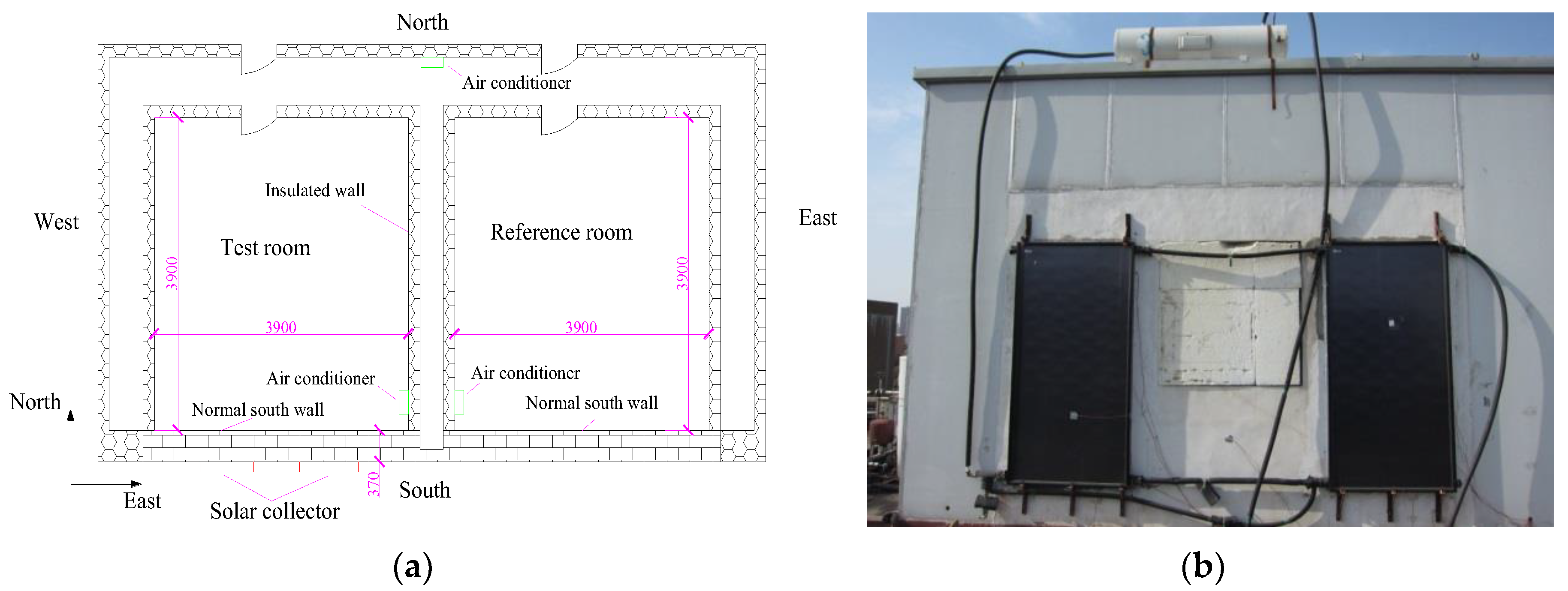
2. Experiment Setup
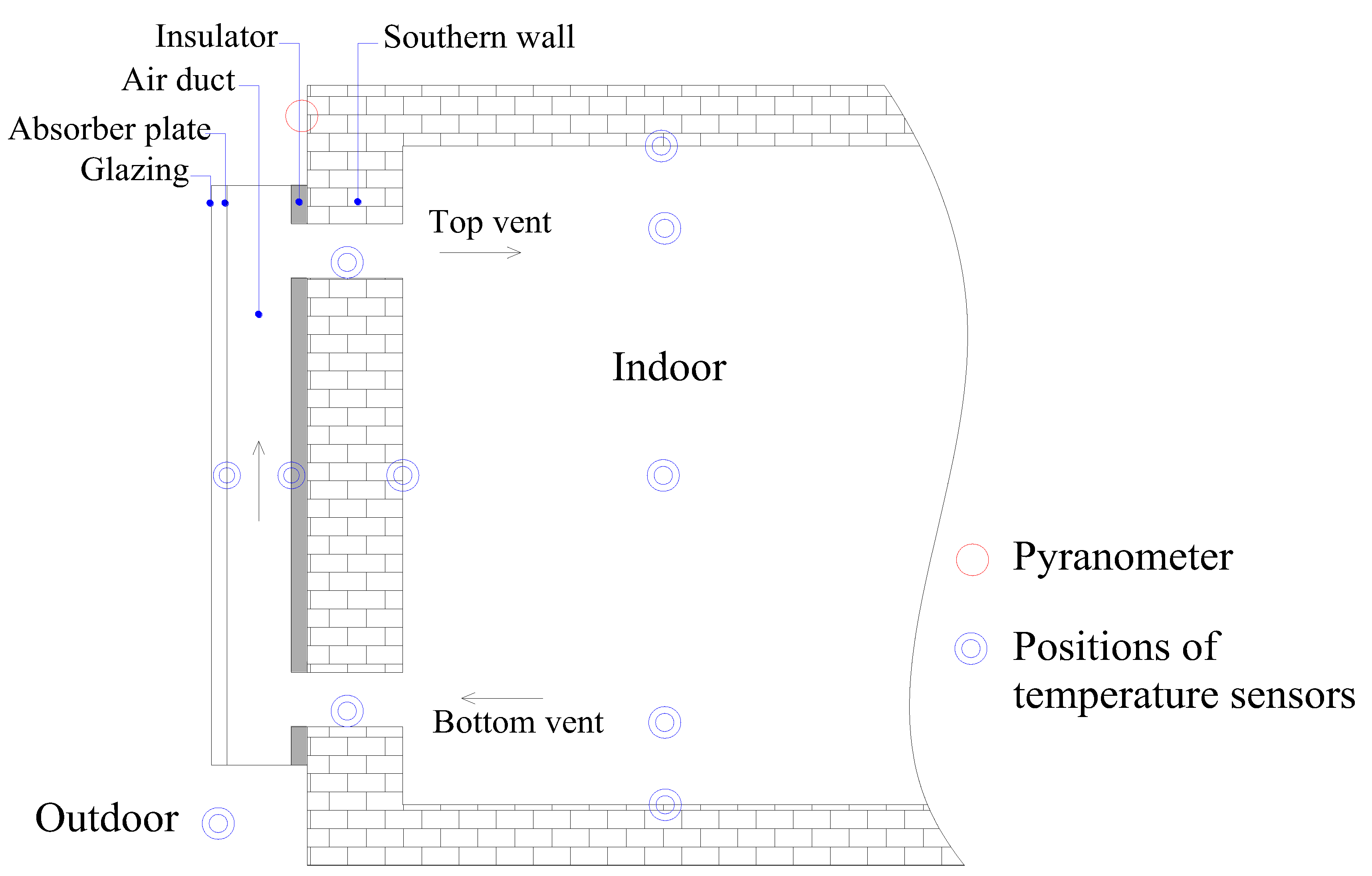
2.1. Description of the DFSC
2.2. Experimental System
3. Numerical Modelling
3.1. Modeling of DFSC
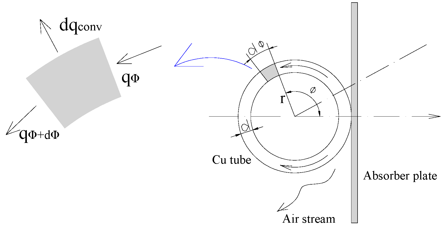
3.1.1. Governing Equations
3.1.2. Relative Heat Transfer Coefficient
3.2. Modeling of Building
3.3. Modeling of Indoor Air
3.4. Numerical Approaches
4. Results and Discussion
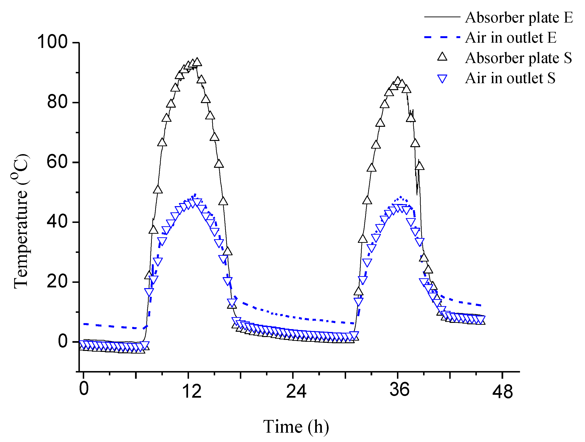
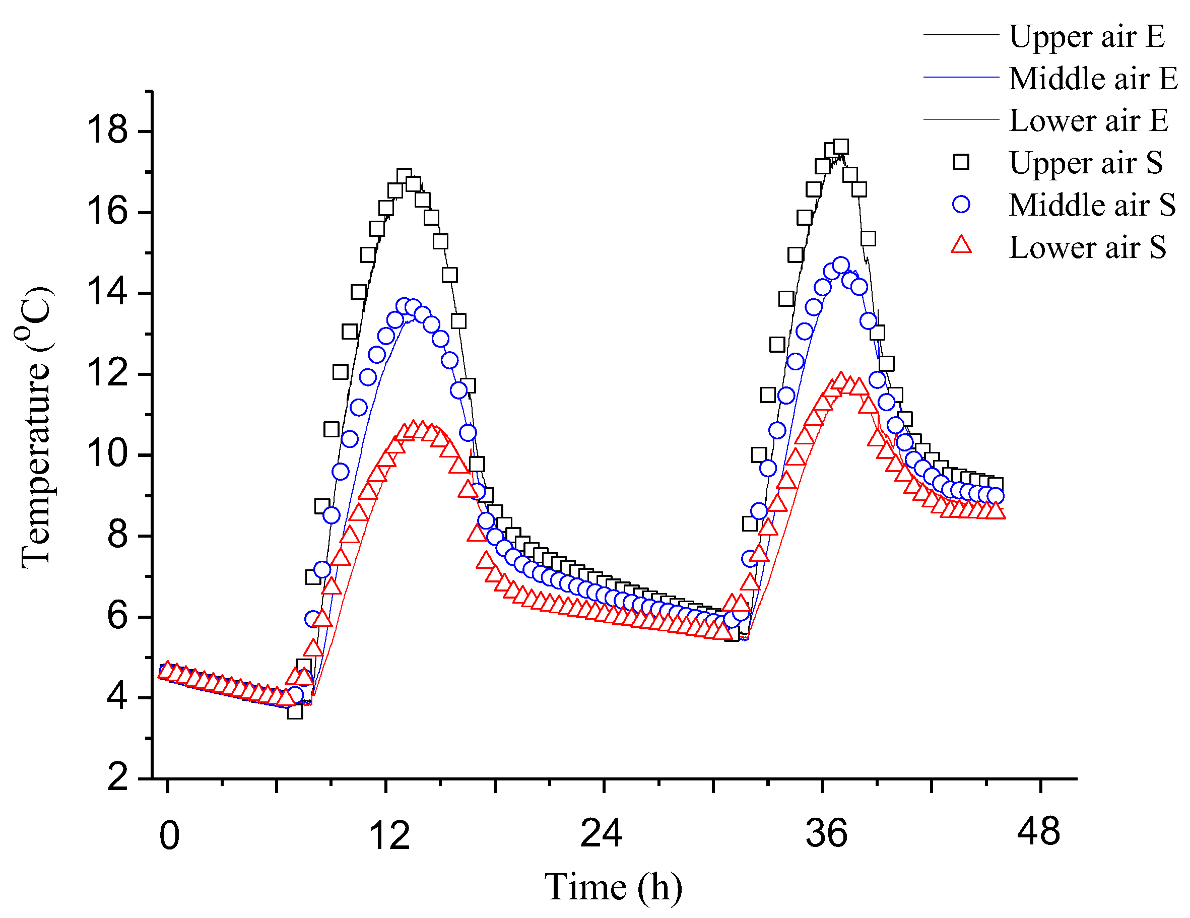
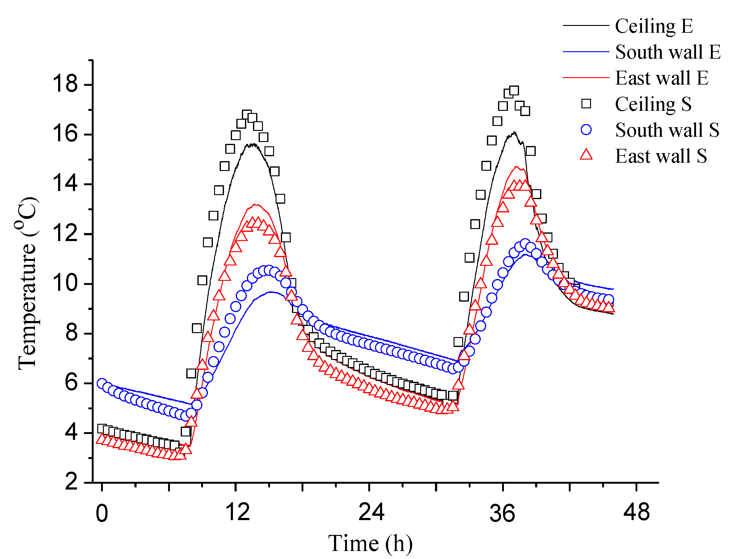
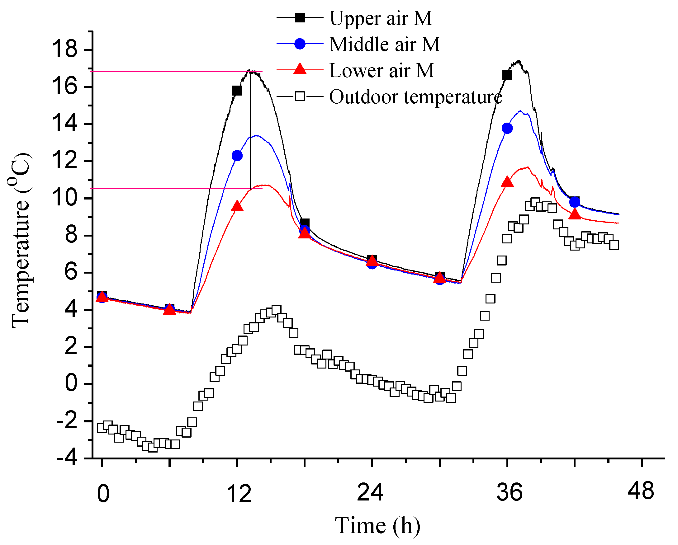
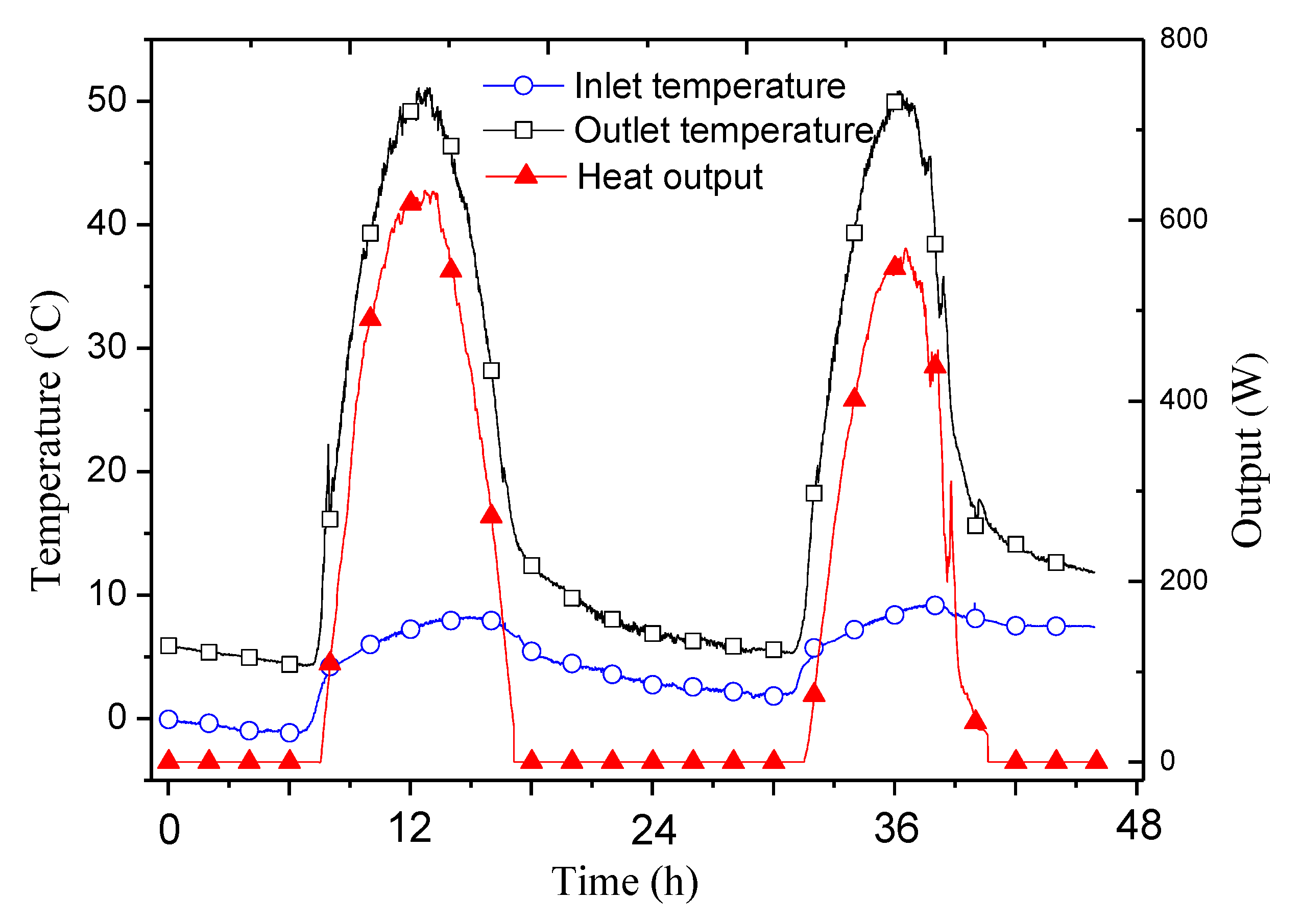
4.1. Model Validation
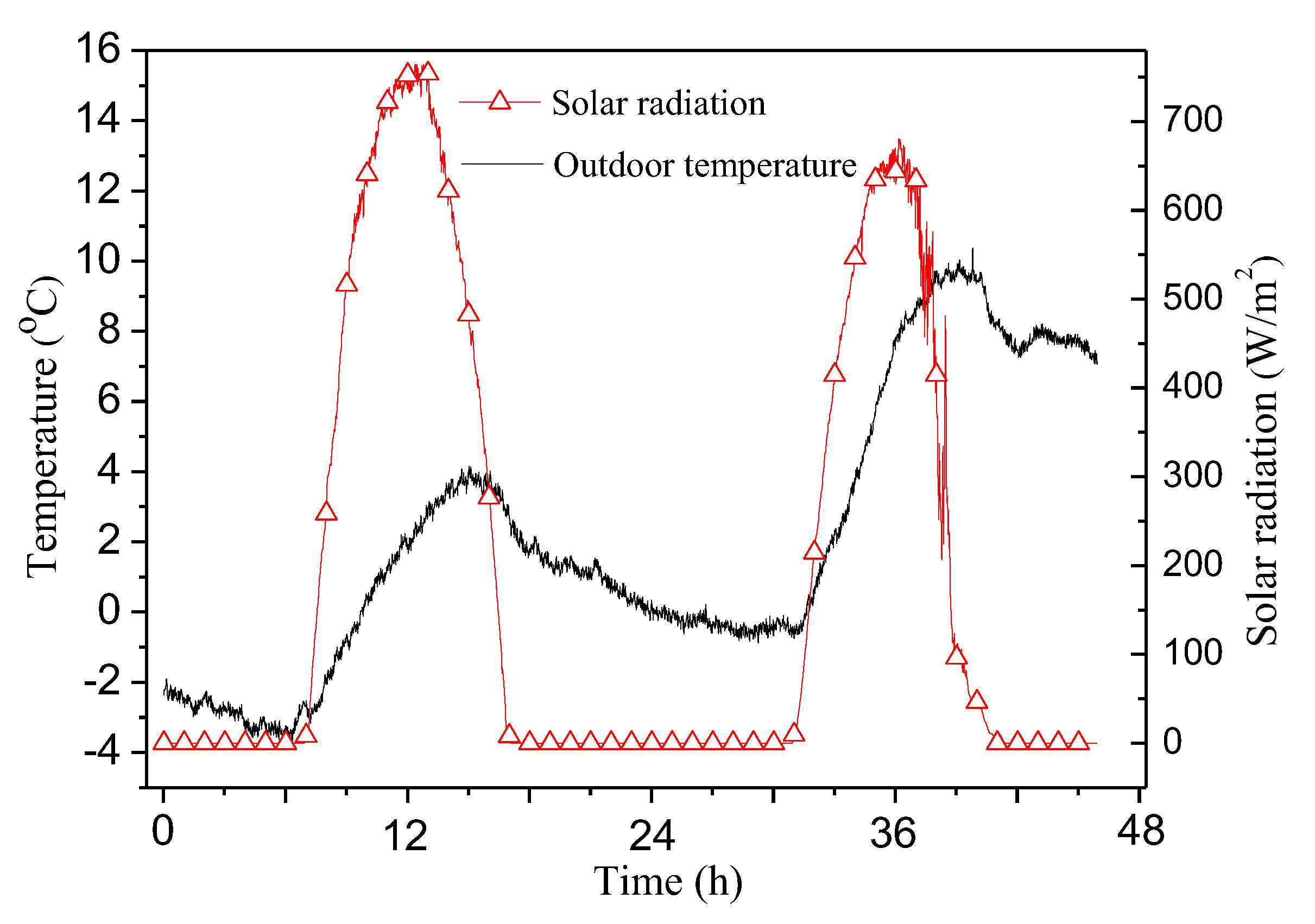
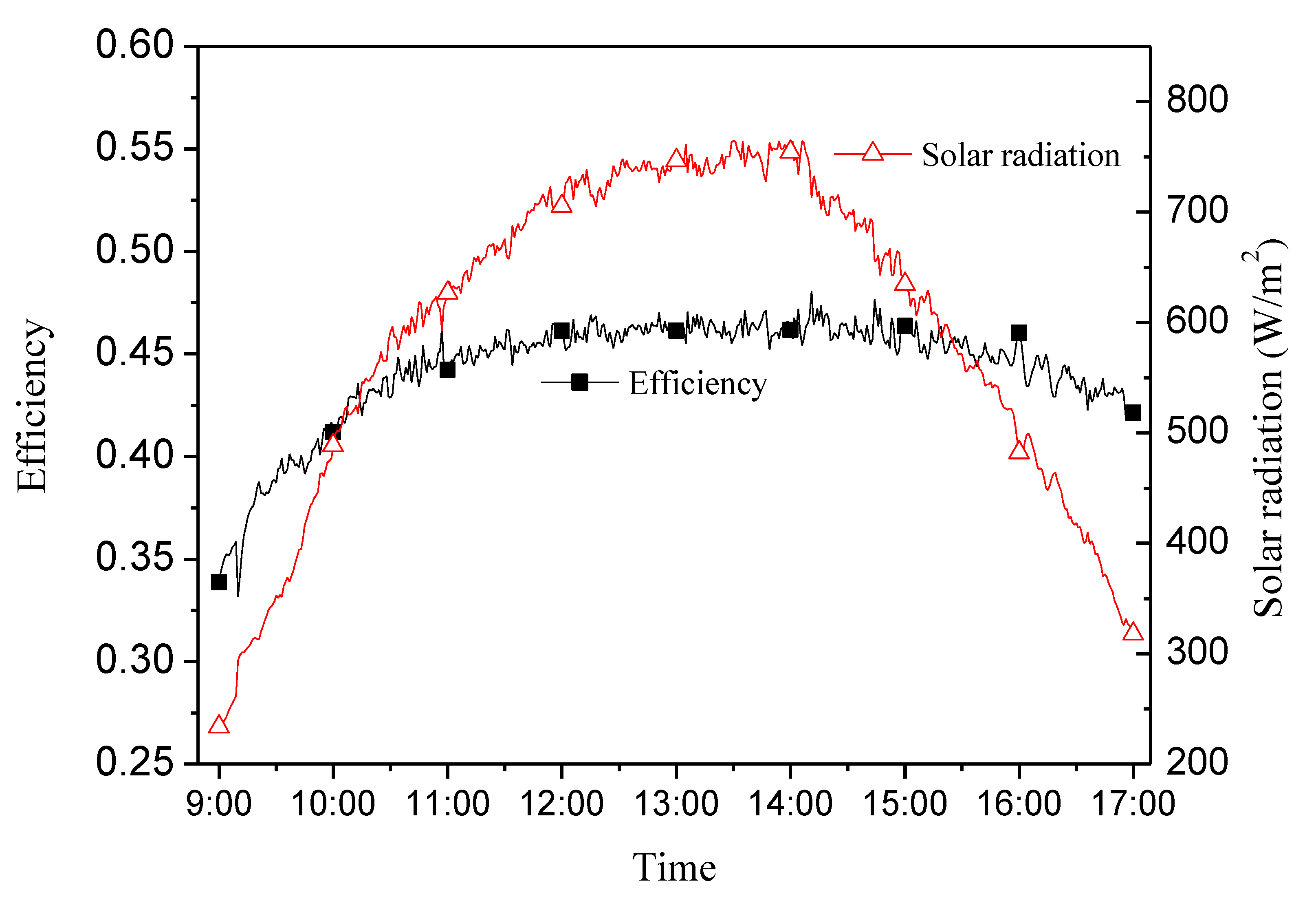
4.2. Experimental Results
4.2.1. Non-Controlled Condition of Indoor Temperature
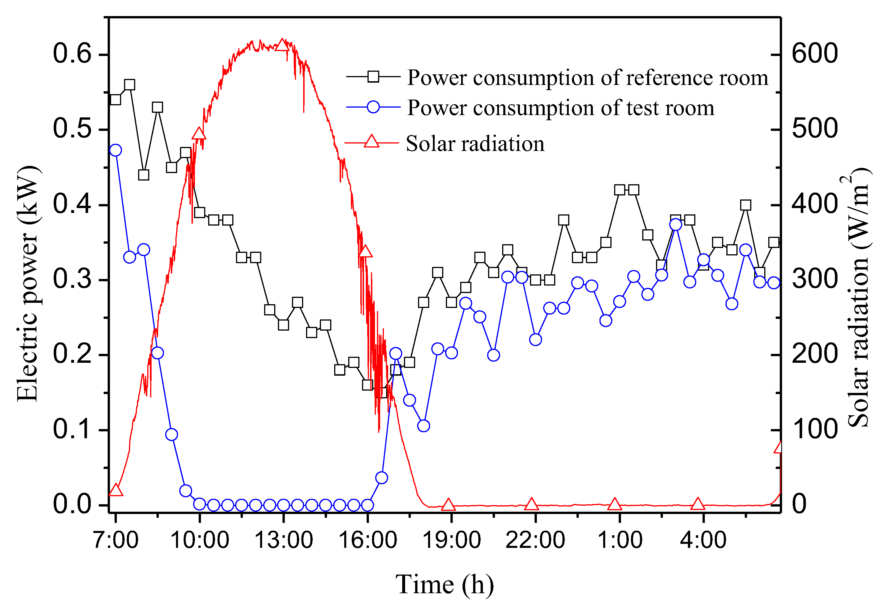
4.2.2. Controlled Condition of Indoor Temperature
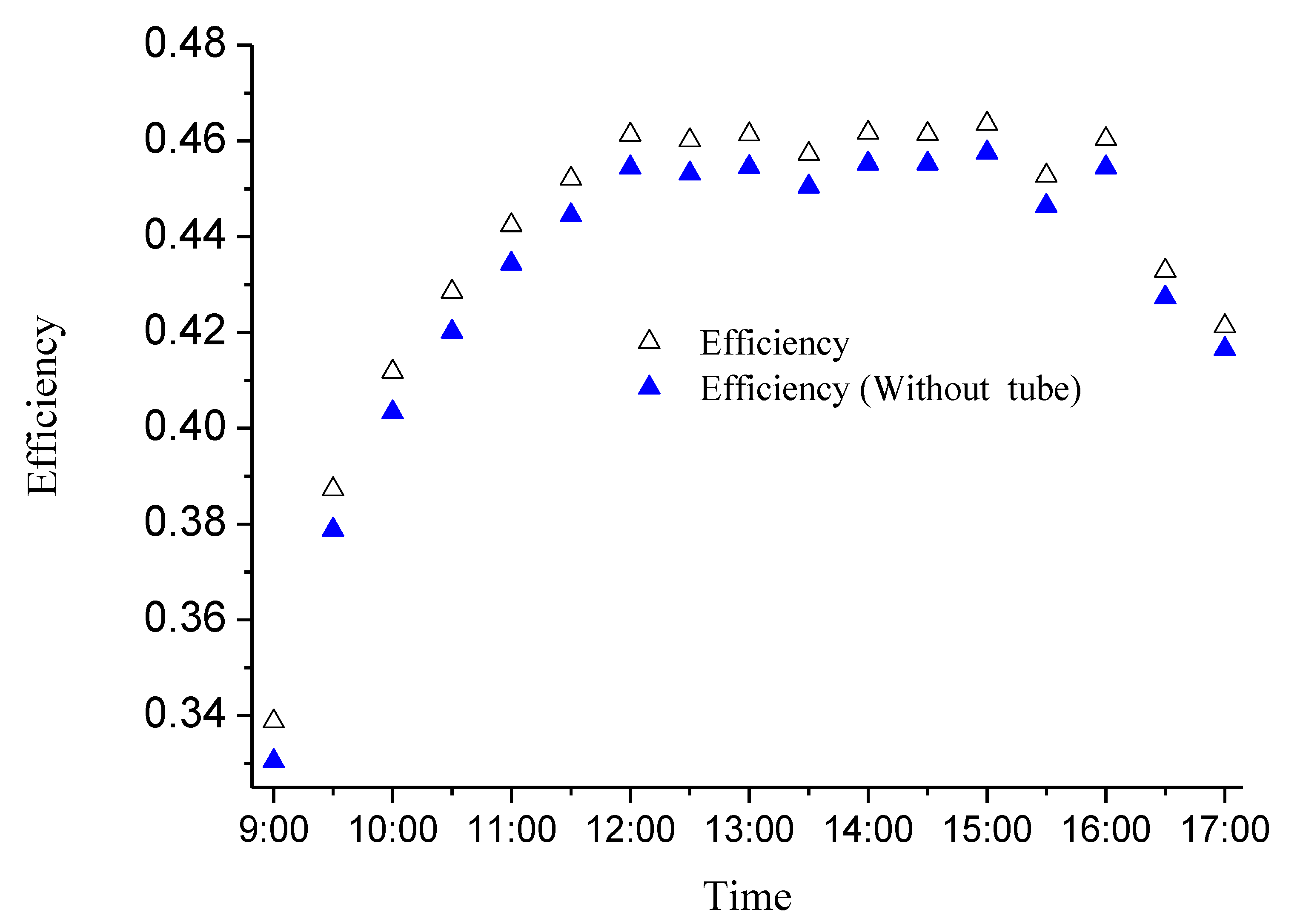
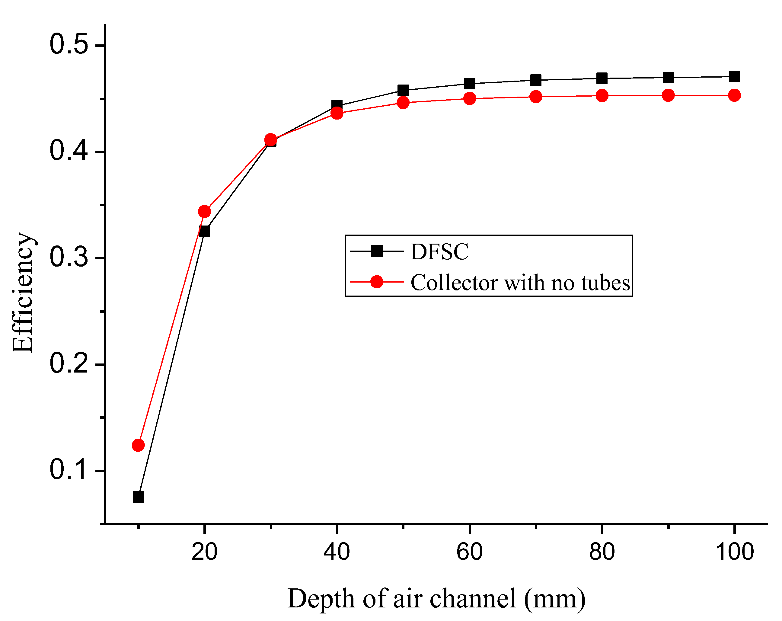
4.3. Effect of Inner Structure
5. Conclusions
Author Contributions
Funding
Conflicts of Interest
Nomenclature
| A | area (m2) |
| C | specific heat capacity (J/kg K) |
| d | thickness or depth (m) |
| De | hydraulic diameter (m) |
| Gr | Glashov number |
| hc | convective heat-transfer coefficient (W/m2 K) |
| hr | radiative heat-transfer (W/m2 K) |
| k | thermal conductivity (W/m k) |
| L | length (m) |
| N | numbers of Cu-tubes |
| P | perimeter (m) |
| q | heat flux (W) |
| r | radius of Cu-tubes (m) |
| S | solar radiation (W/m2) |
| t | time (s) |
| T | temperature (K) |
| u | velocity (m/s) |
| v | volume (m3) |
| w | width (m) |
| Greek symbols | |
| α | absorptivity |
| β | expansion coefficient |
| ε | emissivity |
| η | efficiency |
| λ | friction loss coefficient |
| ν | kinematic viscosity (m2/s) |
| ρ | density, kg/m3 |
| τ | transmittance |
| ξ | partial resistance loss coefficient |
| Subscripts | |
| a | air |
| b | interior plate of backboard |
| f | air stream |
| g | front glazing |
| i | walls in different direction |
| in | inlet |
| out | outlet |
| p | absorbing plate |
| r | insulation |
| s | sky |
| t | Cu-tube |
| w | wall |
References
- Ma, Q.; Fukuda, H.; Lee, M.; Kobatake, T.; Kuma, Y.; Ozaki, A. Study on the utilization of heat in the mechanically ventilated trombe wall in a house with a central air conditioning and air circulation system. Appl. Energy 2018, 222, 861–871. [Google Scholar] [CrossRef]
- Yu, B.; Jiang, Q.; He, W.; Hu, Z.; Chen, H.; Ji, J.; Xu, G. The performance analysis of a novel TC-Trombe wall system in heating seasons. Energy Convers. Manag. 2018, 164, 242–261. [Google Scholar] [CrossRef]
- Hu, Z.; He, W.; Ji, J.; Zhang, S. A review on the application of Trombe wall system in buildings. Renew. Sust. Energ. Rev. 2017, 70, 976–987. [Google Scholar] [CrossRef]
- Bojić, M.; Johannes, K.; Kuznik, F. Optimizing energy and environmental performance of passive Trombe wall. Energy Build 2014, 70, 279–286. [Google Scholar] [CrossRef]
- Corasaniti, S.; Manni, L.; Russo, F.; Gori, F. Numerical simulation of modified Trombe-Michel Walls with exergy and energy analysis. Int. Commun. Heat Mass 2017, 88, 269–276. [Google Scholar] [CrossRef]
- Imessad, K.; Messaoudene, N.A.; Belhamel, M. Performances of the Barra–Costantini passive heating system under Algerian climate conditions. Renew. Energy 2004, 29, 357–367. [Google Scholar] [CrossRef]
- Sun, W.; Ji, J.; Luo, C.; He, W. Performance of PV-Trombe wall in winter correlated with south façade design. Appl. Energy 2011, 88, 224–231. [Google Scholar] [CrossRef]
- Bellos, E.; Tzivanidis, C.; Zisopoulou, E.; Mitsopoulos, G.; Antonopoulos, K.A. An innovative Trombe wall as a passive heating system for a building in Athens—A comparison with the conventional Trombe wall and the insulated wall. Energy Build 2016, 133, 754–769. [Google Scholar] [CrossRef]
- Briga-Sá, A.; Martins, A.; Boaventura-Cunha, J.; Lanzinha, J.C.; Paiva, A. Energy performance of Trombe walls: Adaptation of iso 13790:2008(e) to the portuguese reality. Energy Build 2014, 74, 111–119. [Google Scholar] [CrossRef]
- Mootz, F.; Bezian, J.J. Numerical study of a ventilated facade panel. Sol. Energy 1996, 57, 29–36. [Google Scholar] [CrossRef] [Green Version]
- Burek, S.; Habeb, A. Air flow and thermal efficiency characteristics in solar chimneys and Trombe walls. Energy Build 2007, 39, 128–135. [Google Scholar] [CrossRef]
- Ghrab-Morcos, N.; Bouden, C.; Franchisseur, R. Overheating caused by passive solar elements in tunis. Effectiveness of some ways to prevent it. Renew. Energy 1993, 3, 801–811. [Google Scholar] [CrossRef]
- Stazi, F.; Mastrucci, A.; Perna, C.D. The behaviour of solar walls in residential buildings with different insulation levels: An experimental and numerical study. Energy Build 2012, 47, 217–229. [Google Scholar] [CrossRef]
- Rockendorf, G.; Janssen, S.; Felten, H. Transparently insulated hybrid wall. Sol. Energy 1996, 58, 33–38. [Google Scholar] [CrossRef]
- Ji, J.; Luo, C.; Chow, T.-T.; Sun, W.; He, W. Thermal characteristics of a building-integrated dual-function solar collector in water heating mode with natural circulation. Energy 2011, 36, 566–574. [Google Scholar] [CrossRef]
- Ji, J.; Luo, C.; Sun, W.; He, W.; Pei, G.; Han, C. A numerical and experimental study of a dual-function solar collector integrated with building in passive space heating mode. Chin. Sci. Bull. 2010, 55, 1568–1573. [Google Scholar] [CrossRef]
- González-González, S.L.; Tejero-González, A.; Rey-Martínez, F.J.; Andrés-Chicote, M. Alternative for summer use of solar air heaters in existing buildings. Energies 2017, 10, 985. [Google Scholar] [CrossRef]
- Shen, J.; Lassue, S.; Zalewski, L.; Huang, D. Numerical study on thermal behavior of classical or composite Trombe solar walls. Energy Build 2007, 39, 962–974. [Google Scholar] [CrossRef]
- Bejan, A. Convection Heat Transfer, 4th ed.; John Wiley &Sons: Hoboken, NJ, USA, 2013. [Google Scholar]
- Beausoleil-Morrison, I. The Adaptive Coupling of Heat and Air Flow Modelling within Dynamic Whole-Building Simulation. Ph.D. Thesis, University of Strathclyde, Glasgow, UK, 2000. [Google Scholar]


| Materials | Density (kg/m3) | Specific Heat (J/kg K) | Thermal Conductivity (W/m K) | Absorptivity | Emissivity | Thickness (mm) |
|---|---|---|---|---|---|---|
| Glazing 1 | 2500 | 750 | 1.05 | 0.038 | 0.83 | 3.2 |
| Absorber | 2720 | 933 | 237 | 0.9 | 0.05 | 0.4 |
| Insulation | 15 | 1210 | 0.04 | - | - | 20 |
| Cu-tubes | 8933 | 397 | 393 | - | - | 0.8 |
| Materials | Density (kg/m3) | Specific Heat (J/kg K) | Thermal Conductivity (W/m K) | Absorptivity | Emissivity | Thickness (mm) |
|---|---|---|---|---|---|---|
| Brick (SW) | 1920 | 835 | 0.72 | 0.5 | 0.9 | 370 |
| Steel panel | 8030 | 502 | 16.27 | 0.5 | 0.9 | 0.5 |
| Polystyrene | 15 | 1500 | 0.04 | - | - | 300 (F)/50 (W) |
| Position | Mean Deviation (°C) |
|---|---|
| Absorber plate | 1.2 |
| Outlet of DFSC | 2.6 |
| Indoor air (up/middle/low) | 0.4/0.43/0.45 |
| Interior surfaces of envelop (ceiling/south/east) | 0.74/0.39/0.46 |
© 2018 by the authors. Licensee MDPI, Basel, Switzerland. This article is an open access article distributed under the terms and conditions of the Creative Commons Attribution (CC BY) license (http://creativecommons.org/licenses/by/4.0/).
Share and Cite
Ma, J.; Zhao, Q.; Su, Y.; Ji, J.; He, W.; Hu, Z.; Fang, T.; Wang, H. The Thermal Behavior of a Dual-Function Solar Collector Integrated with Building: An Experimental and Numerical Study on the Air Heating Mode. Energies 2018, 11, 2402. https://doi.org/10.3390/en11092402
Ma J, Zhao Q, Su Y, Ji J, He W, Hu Z, Fang T, Wang H. The Thermal Behavior of a Dual-Function Solar Collector Integrated with Building: An Experimental and Numerical Study on the Air Heating Mode. Energies. 2018; 11(9):2402. https://doi.org/10.3390/en11092402
Chicago/Turabian StyleMa, Jinwei, Qiang Zhao, Yuehong Su, Jie Ji, Wei He, Zhongting Hu, Tingyong Fang, and Haitao Wang. 2018. "The Thermal Behavior of a Dual-Function Solar Collector Integrated with Building: An Experimental and Numerical Study on the Air Heating Mode" Energies 11, no. 9: 2402. https://doi.org/10.3390/en11092402