1. Introduction
Latent heat storage (LHS) using phase change materials (PCM) as storage media is known for its potential to deliver very high energy densities, compared to sensible storage vessels, as well as a constant temperature heat output [
1,
2,
3,
4,
5]. However, the low thermal conductivity of PCM results in poor heat transfer characteristics in conventional LHS units [
6]. Direct contact heat exchange in LHS systems has been proposed as a means to increase heat transfer and enable fast charging and discharging of the storage [
7,
8]. Direct contact latent heat storage (DCLHS) is based on a direct flow of the heat transfer fluid (HTF) through the PCM. In cases where the HTF has a lower density than the PCM, the HTF is pumped at the bottom of the storage to form bubbles. The bubbles flow upwards and simultaneously release or absorb heat causing the melting or solidification of the PCM. Such types of storage can contain up to 90% PCM resulting in very high energy densities. The ability to generate large heat exchange surface area at the interface of the HTF bubbles and the PCM can result in high thermal power output [
9,
10,
11]. Furthermore, the agitation caused by the HTF bubbles has been reported to reduce both the supercooling and phase segregation during crystallization of salt hydrates [
12]. In addition to the advantages presented above, DCLHS systems are relatively simple systems and avoid the usage of heavy and complicated structures, which could potentially lead to significant cost reduction in comparison to conventional LHS systems [
13,
14].
However, experimental investigations with direct contact latent heat storage (DCLHS) have also proved to be challenging. As reported by Stockeler [
15], when using Glauber salt (Na
2SO
4·10 H
2O) as PCM and kerosene as HTF, the formation of an undesired emulsion between the two phases was observed. This led the liquid PCM to exit the storage tank in the form of dispersed droplets in the HTF, therefore entering the piping system and pumps. During the cooling process of the HTF, the leaked PCM can crystallise and accumulate in the system, causing a general blockage [
16,
17]. Similar problems have been observed in preliminary experiments conducted at a DCLHS setup at Lucerne University of Applied Sciences and Arts using tetra-
n-butylammonium bromide (TBAB)/water mixtures as PCM and thermal oil as HTF [
18]. Such issues were more significant with a smaller nozzle size [
16]. While it is of interest to generate smaller droplet sizes in DCLHS systems to enable higher heat exchange rates due to increased contact area and therefore higher heat power outputs, small droplets tend to increase the tendency of the two phases to form an emulsion [
17].
This study aims to develop solutions to reverse the emulsification observed in DCLHS by achieving a fast separation of the emulsion before PCM enters the piping and pumping system. A fast demulsification will allow for higher HTF flow rates and therefore a higher power output of the DCLHS without the danger of a system blockage. Four different methodologies have been examined for their ability to enable the fast separation of an emulsion comprising of an oil and a water-based phase. Superhydrophobic filters were recognized as the most promising technique to separate such emulsions in conditions simulating those of a DCLHS application. This is the first time superhydrophobic filters have been examined in the context of DCLHS to the best of the authors’ knowledge.
2. Emulsion Separation Concepts and Evaluation
Separation methods should be affordable and energy efficient. The energy required by the separation process should be the least possible to minimize adverse effects on the roundtrip efficiency and the economics of the storage systems. Furthermore, the method should possess a long lifetime, as well as low maintenance expenses and investment cost. Finally, the technique should be easy to integrate in the overall storage system and should be effective for as many uninterrupted operation hours as possible before regeneration or maintenance is required. Based on these criteria, the following emulsion separation techniques were considered in this study:
Centrifugation: it applies the principle of sedimentation, where a centrifugal acceleration causes denser particles to move to the outer edges of the samples container, while the lighter ones accumulate in the center. In order to be of valuable use for DCLHS applications, a continuous liquid-liquid centrifuge must be used, to enable continuous operation of the storage system.
Chemical demulsifiers: These are substances that can be added to the storage tank to act directly on the interfacial layer between the two fluids which prevents the coalescence of the emulsion droplets. Demulsifiers are thought to weaken this layer thus destabilizing the emulsions [
19]. Demulsifiers have been frequently used to break water-in-crude-oil emulsions in petrochemical industry applications.
Filtration methods: filtration is a physical separation method that separates two phases, such as liquid-solid or liquid-liquid, by adding a barrier through which only one of the two phases can pass. In this study: (i) a hydrophilic glass membrane and (ii) a superhydrophobic filter are considered. As described by other works, mainly two different types of filtration methods can be listed for separating water in oil emulsions: hydrophilic membranes, which work as a coalescence separator [
20,
21] and superhydrophobic filter, which are permeable to the oil phase and impermeable to the aqueous phase [
22,
23,
24].
The methods were evaluated using literature and market data. The results were summarized and the advantages and disadvantages were compared based on seven different criteria, shown in
Table 1. The separating techniques were ranked based on the grade obtained for each evaluation criteria; grades were assigned from a minimum value of 1 to a maximum of 6, with a maximal possible score of 42 for each technique. Hydrophilic glass membranes have been shown to achieve relatively high separation grades [
21] with expected low maintenance costs and good system integration capabilities. Superhydrophobic filters were shown to have similar characteristics but with higher separation efficiency and very high permeability [
24] which leads to lower expected energy consumption from the pump. The life times of both filtration methods are not known. Centrifuges, on the other hand, possess a very long lifetime as well as a very high separation efficiency, but the investment costs and the energy demand are much higher. This would make a DCLHS system ecologically unsustainable. The utilization of chemical demulsifiers, is a promising techniques but very little data was found on their performance in similar systems as the one considered in this study and are therefore characterized by a high uncertainty both on the separating efficiencies and lifetimes, which reflects on their ranking.
The superhydrophobic filter was chosen as the best solution for the problem at hand to separate a water in oil (w/o) emulsion, mainly due to low investment and maintenance costs, high separation rate, and low energy demand. However, as previously stated, the lifetime of such a filter remains uncertain. Superhydrophobic surfaces have gained attention in different fields of interest, such as water repelled surfaces for self-cleaning materials [
25,
26], production of anti-corrosion and anti-fouling surfaces [
27] as well as oil-water separation [
23,
24,
28,
29].
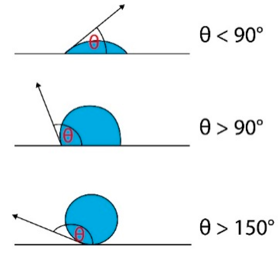
A key figure for understanding filtration as a separation technique and the behavior of surfaces towards water or oil, is the contact angle which measures the wettability of a solid surface by a liquid.
Figure 1 shows the different contact angles θ of a polar drop on a surface. Generally, if θ < 90°, the surface is considered to have an affinity towards polar compounds and water, therefore it is defined as hydrophilic. On the contrary, if θ > 90° the surface rejects all polar compounds and has higher affinity to nonpolar substances such as oils, and is defined as hydrophobic. A surface is said to be superhydrophobic if θ > 150° [
30].
3. Materials and Methods
For reasons of time consumption and to ensure reproducible conditions for all demulsification experiments, it was decided to use artificially generated TBAB/water/oil emulsions to determine filtration efficiency instead of using emulsions formed directly at the DCLHS setup. However, the synthesised water/oil emulsions utilized in this study were designed to replicate the ones formed in an existing DCLHS setup with thermal oil as HTF and TBAB/water as PCM [
18] where emulsification issues had been identified in previous studies [
16]. To ensure the resemblance of the real and artificial emulsions, a total of six emulsion samples were extracted from the DCLHS system, they were thoroughly characterized and compared to artificial emulsions created by mixing water/TBAB and oil under different conditions. Once the characterization of the artificial samples showed a satisfactory match to the properties of the real samples, the demulsification experiments could be started.
3.1. DCLHS Setup–Collection of Baseline Emulsions
As mentioned beforehand, to understand the characteristics of emulsions created in DCLHS setups, samples were collected during an experiment with a real laboratory-scale setup where thermal oil was used as HTF, while a water–TBAB mixture (mass ratio 60:40) was used as PCM.
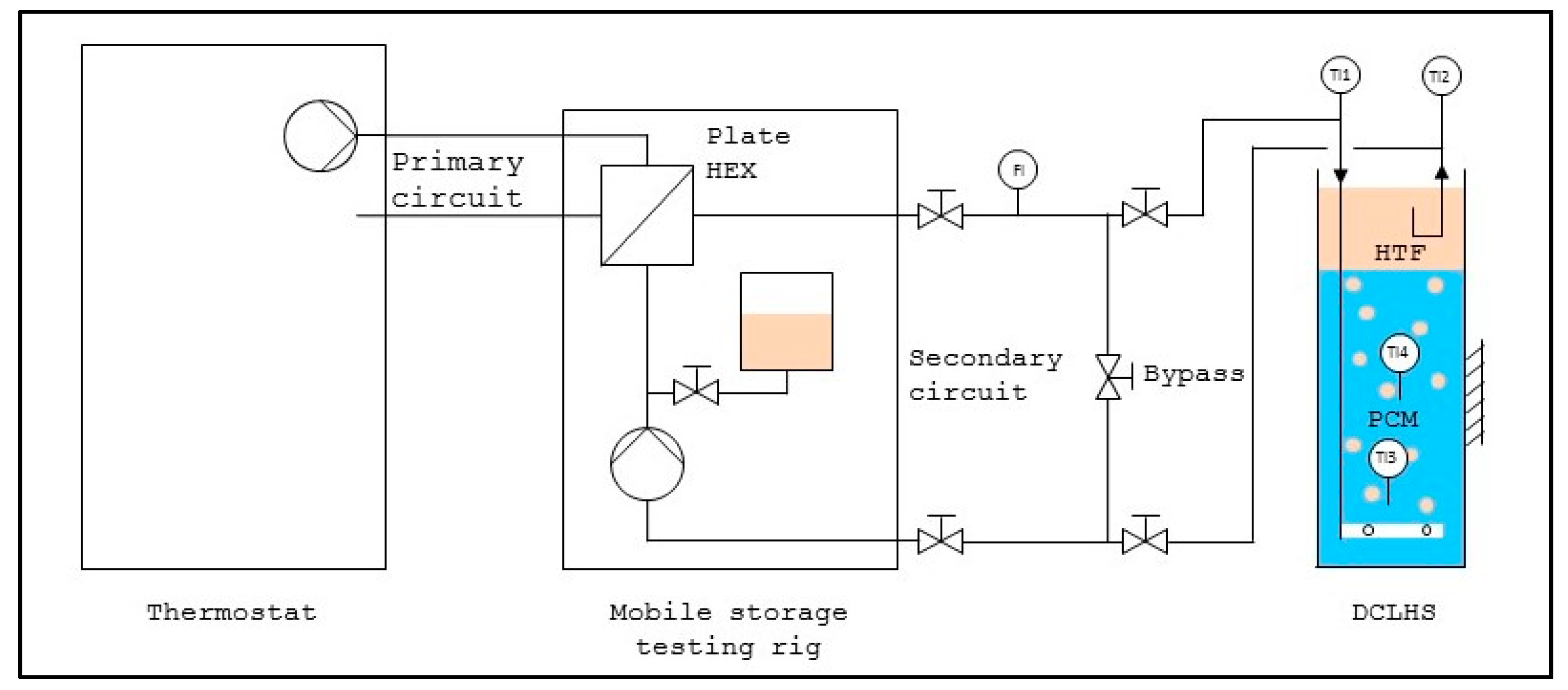
Figure 2 shows the schematic flow chart of the DCLHS setup [
16,
18].
The temperature of the HTF was regulated via a plate heat exchanger (HEX) from the thermostat in the primary circuit on the left side. The HTF was pumped through a nozzle system placed at the bottom of the storage vessel. The oil bubbles ascended, while exchanging heat with the PCM and the oil was collected at the top of the tank. The HTF was subsequently pumped out of the storage vessel then pumped through the plate HEX. An emulsification of PCM in HTF was observed at the exit of the nozzle system, where the oil was exiting and meeting the PCM at a high speed. The residence time of the oil in the main volume and top section of the DCLHS was not long enough for the emulsion to separate. Therefore the pump drew in the emulsion instead of pure oil and transferred it in the piping system. During the crystallisation process the leaked PCM solidified and accumulated in the plate HEX where it led to a blockage of the whole DCLHS system. More information on the setup can be found in [
16,
18].
For the requirements of these studies experiments were conducted with two different HTF mass flow rates (30 kg·h−1 and 60 kg·h−1) to analyse the influence of the mass flow on the emulsion characteristics. A total of six emulsion samples were collected and analysed as shown in the following section. To get a uniform, steady emulsion, the DCLHS had been continuously operating for one hour prior to the extraction of the samples.
3.2. Emulsion Characterization
A set of emulsion parameters were chosen to characterize the emulsion produced in the DCLHS setup as well as the ones artificially produced: mass ratio of the PCM phase in the emulsion, separation time of the emulsion into two separate phases and droplet size distribution.
3.2.1. Mass Ratio of PCM in Emulsion
The first emulsion parameter selected for characterization and comparison between natural and artificial emulsion was the mass ratio between the continuous and discontinuous phases. To determine the mass ratios of the PCM and HTF in the emulsion, the water was evaporated out of the emulsion on a heating plate under stirring until there was no change in weight measured. The weight was measured before and after the evaporation process. With the difference, the mass ratio of water and subsequently of water/TBAB was calculated.
3.2.2. Separation Time of the Emulsion/Emulsion Stability
The separation time is an important parameter because it shows how stable an emulsion is: a higher separation time means a more stable emulsion. The separation time was measured with the LUMiSizer
® by LUM GmbH (Berlin, Germany). The LUMiSizer
® is a photo centrifuge which allows measuring space-and-time-resolved-extinction-profiles (STEP™-Technology, from LUM GmbH) [
31]. By knowing the acceleration in the LUMiSizer
® (
), and the gravitational acceleration (
), the separation time at gravitational acceleration (
) could be calculated with the following Equation (1):
where
is the accelerated separation time as it is measured by the LUMiSizer
®. The emulsion stability as a function of time was represented using the instability index, as it was calculated by the software SEPView
® (Version 6.4.160.5025, LUM GmbH, Berlin, Germany).
3.2.3. Droplet Size Distribution
The droplet size is also an important characteristic of an emulsion. Generally, smaller mean drop size results in a higher stability, which leads to higher separation times [
32]. The drop size distribution was measured as well by means of a LUMiSizer
® using the method explained in [
31].
3.3. Production of Artificial Emulsions
To receive comparable results for the filtration process, the emulsion spontaneously formed in the DCLHS setup was reproduced in the laboratory. TBAB/water and thermal oil were combined in the mass ratio determined in the previous step, then subsequently emulsified with a Miccra D-15 disperse homogenizer (Heitersheim, Germany) equipped with a Miccra DS20/PF SMIR attachment at a rotation frequency of 8800 min−1. Different shear times from one second up to two minutes were tested. The resulting emulsion samples were analysed with the same methodology reported above used for the emulsions produced in the DCLHS setup. The properties of the original and the artificially produced samples were compared and the production conditions resulting to an emulsion closer to the original one were selected.
3.4. Production of Superhydrophobic Filter
For the production of the filters, a similar methodology was used as the one described in [
23], where to produce the superhydrophobic filter commercial melamine sponges (100 × 60 × 20 mm) were treated with SE7100 (Midland, MI, USA). In the present study a superhydrophobic filter was created by treating a melamine sponge with adhesives of similar structure, namely, CAF1 and CAF4 polydimethylsiloxane (PDMS)-based adhesives (Bluestar Silicones Elkem, Oslo, Norway). The filters were prepared in different steps: first, the melamine sponges were soaked in a solution of 5 g adhesive and 60 figure EtOAc. Then, they were compressed between two metal plates from 20 mm to a thickness of 4 mm. Superfluous solution leaked during the pressing process and was discarded. Finally, the sponge was cured at room temperature for 16 h, after which the pressure exerted by the two metallic plates was released. As seen in,
Figure 3 the filter showed a slight expansion after the applied pressure was released, with a higher enlargement in the middle of the sponge compared to the edges.
3.5. Evaluation of Filtration Efficiency
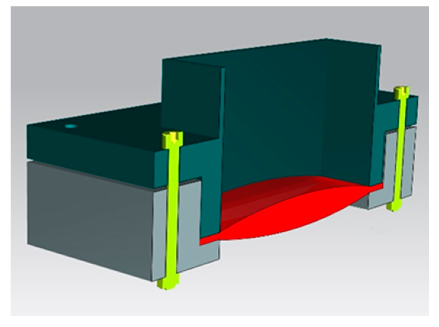
In a first step the hydrophobicity of the filter was optically determined based on the contact angle of single water droplets using a VHX-100 microscope (KEYENCE, Osaka, Japan). Subsequently, the permeability of the filter was evaluated by pouring artificial emulsion on the filter. Initially, 100 mL of the emulsion were used. In further tests the amount of the emulsion to be filtered was increased up to 500 mL and 1500 mL. During the filtration tests, the filter was fixed in a filter holder, the rendered image of which is shown in
Figure 4.
As described shortly in the previous pages, when the mixture to be separated (feed) comes in contact with the filter, only one phase (filtrate) is able to pass through, while the retained phase (retentate) is captured by the filter itself. The key figures for filtration processes are the mass velocity Equation (2) and the permeability Equation (3):
The permeability (
) shows how much mass of feed (
) can pass through the filter in the given time under a certain pressure difference (
) on a specified surface area (
A). The hydrostatic pressure is given by the height of the emulsion column on the filter (
h), the gravitational acceleration (
g) and the density of the emulsion (
) as reported in Equation (4) below.
After the filtration process was finished, the purity of the filtrate and therefore the ability of the filter to retain the water phase was analysed via optical observation.
4. Results and Discussion
4.1. Characterization of Emulsions Produced in DCLHS setup
4.1.1. Mass Ratio of PCM in Emulsion
The average mass ratio of the PCM () in the emulsion at HTF mass flow rates of 30 kg/h and 60 kg/h were found to be and respectively. Therefore under these conditions the mass flow rate did not influence the amount of PCM emulsified in oil phase.
4.1.2. Separation Time of the Emulsion/Emulsion Stability
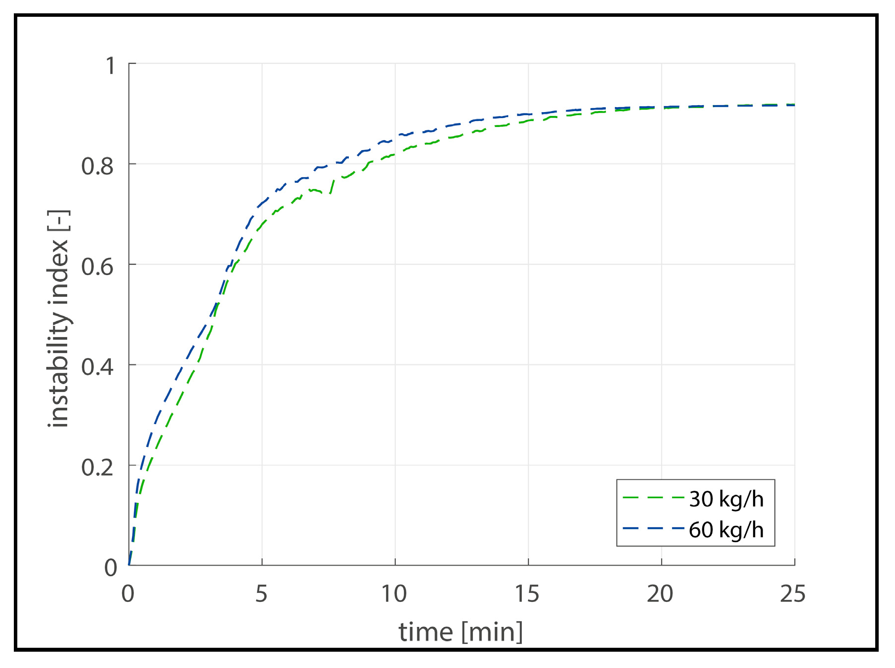
Figure 5 shows the instability index as a function of time for the emulsion samples obtained from the DCLHS setup for both mass flow rates examined. The average values are shown from measurements conducted in the samples obtained at 30 kg/h and three samples at 60 kg/h HTF mass flow rate.
As it can be observed, there is almost no difference in the instability profile of two emulsions. It was assumed that the separation of the two phases occurred in the area where the curves level off after approximately 5 min. Based on this definition of the accelerated separation time and Equation (1), the separation time at gravity conditions could be calculated to be 50 h. This separation time is in accordance with the observation of the DCLHS setup, where the emulsion separated completely after two to three days after switching off the setup.
4.1.3. Droplet Size Distribution
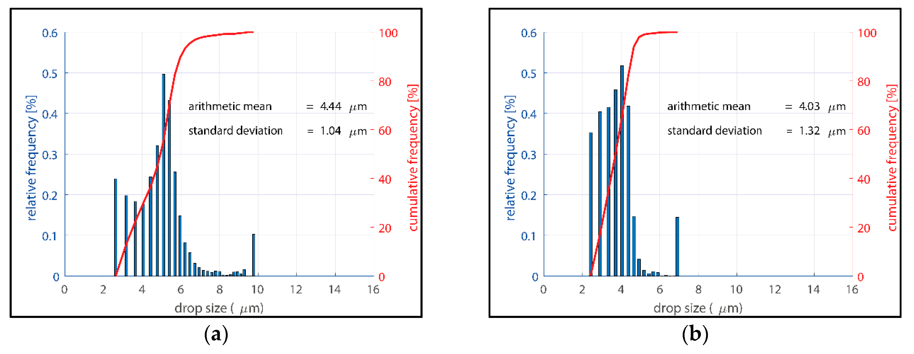
Figure 6 shows the PCM droplet size distribution of the two emulsions created in the DCLHS setup. The x-axis shows the drop size in µm. The left y-axis shows the relative frequency of the different drop sizes (blue bars), while the right y-axis shows the cumulative frequency (red line). Two similar and uniformed macro emulsions were built. All droplets from the 30 kg s
−1 emulsion are located between 2.5–10 µm and the arithmetic average is 4.44 µm, while the droplets from the 60 kg·s
−1 emulsion are located between 2.5 and 7 µm resulting to a lower arithmetic average of 4.03 µm.
4.2. Evaluation of Synthesized Emulsion
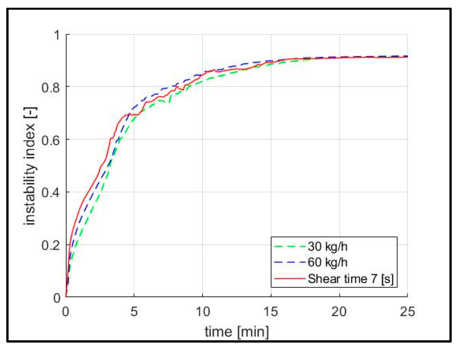
Synthesized emulsions produced under different conditions were also tested in regards to stability and drop size distribution. The shear time was iteratively adapted to obtain a similar stability to the DCLHS emulsion. The best results were obtained for a shear time of seven seconds.
Figure 7 shows the transient instability index as a function of time for the two emulsions from the laboratory setup and the artificial emulsion with a shear time of seven seconds. The instability curve of the artificial emulsion with a shear time of seven seconds is located in the range of the two emulsion produced from the laboratory setup during the whole analysis time. Therefore it can be concluded, that the reproduced emulsion would separate at gravitational acceleration around the same time as the emulsions from the laboratory setup.
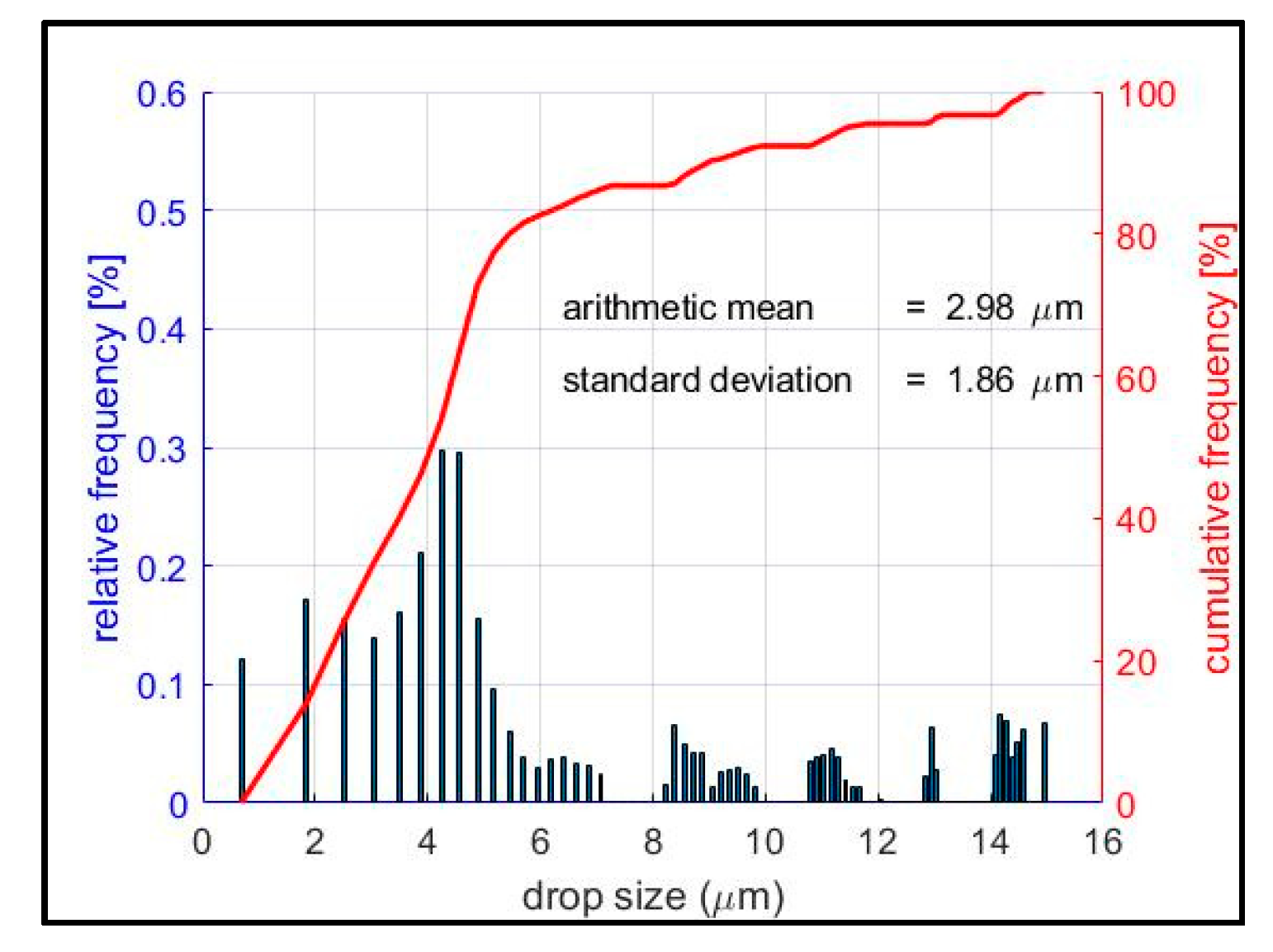
Figure 8 shows the droplet size distribution of the reproduced emulsion with a shear time of seven seconds. Compared to the emulsion from the laboratory (see
Figure 6) there are some noticeable differences. All drops are situated between 1 and 15 µm. This means that the reproduced artificial emulsion shows broader drop size distribution compared to the emulsion from the DCLHS setup. The smallest drops have a size of 1 µm compared to the drops of 2.5 µm from the laboratory emulsions, while the largest ones have a size of 15 µm instead of 10 µm or 7 µm measured in the DCLHS emulsion. The smaller drops reduce the arithmetic average down to 2.98 µm. Nevertheless, the majority of the drops fall in the same area size range as in the original emulsion. Around 80% of the drops from the laboratory emulsion and about 60% of the drops from the artificial emulsion are in the range of 3–7 µm.
The lower homogeneity of the replicated emulsion could be attributed to the short shear time (7 s). However, the shear time could not be increased as it was not possible to further reduce the shear rate due to equipment restrictions. Since the droplet size distribution is wider in the case of the artificial emulsion, it can be assumed that if the separation method is effective for the replicated emulsion, then it will be effective for the laboratory emulsion as well. Therefore, the artificial emulsion with 7 s shear rate was used for the filtration experiments.
4.3. Filter Characterisation
No significant differences were observed in the structure and the performance of the two filters produced with CAF 1 and 4, therefore only the results with the CAF 1 are presented.
To quantify the amount of adhesive in the sponge, weight measurements before the treatment and after the curing process were conducted. They showed an average of 2 g of adhesive per sponge. The examination under the microscope after the treatment showed an inhomogeneous accumulation of the adhesive on the sponge.
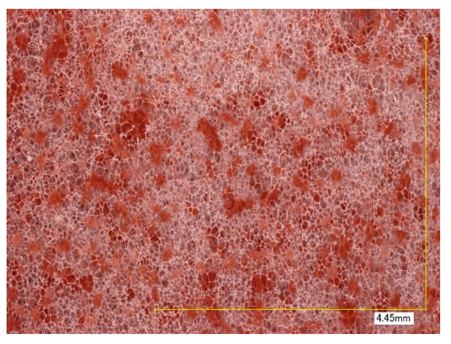
Figure 9 shows the top side of a sponge treated with CAF1 (red adhesive).
Adhesive deposits are heterogeneously distributed and random in their size.
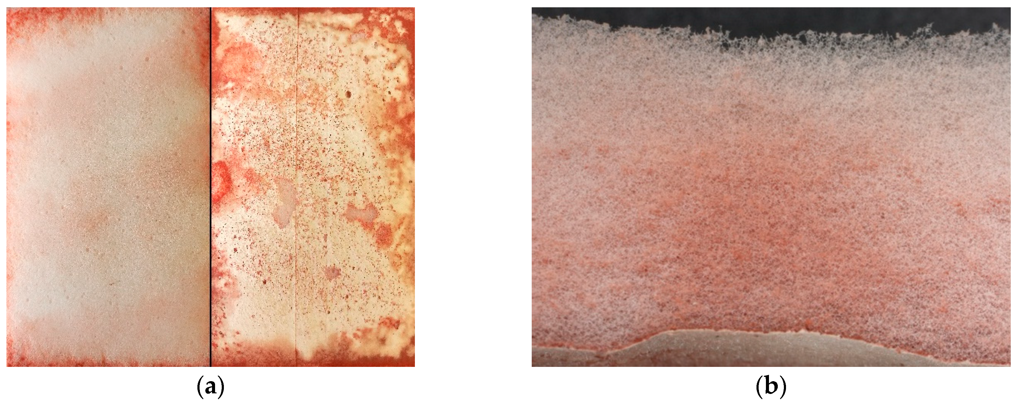
Figure 10a shows the unmagnified topside and bottom side of the sponge. The topside shows different slightly redder spots where the adhesive accumulates. On the other hand, the bottom side shows an almost continuous layer of adhesive, with accumulation around the edges.
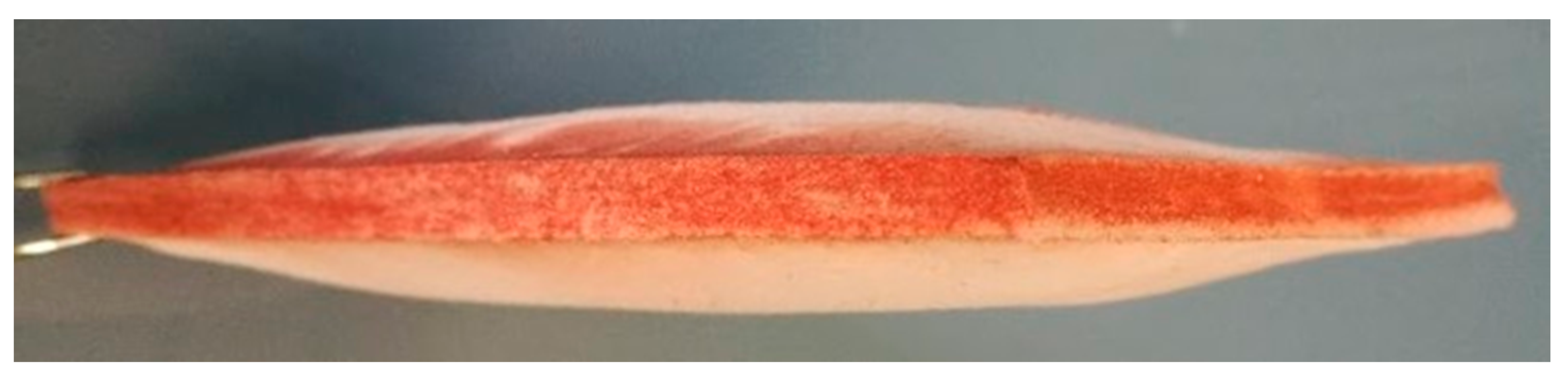
Figure 10b shows a sectional view of the melamine sponge. The higher accumulation of CAF1 towards the bottom side of the sponge is clearly visible. The reason lays in the curing process: during the whole duration of the curing process, the sponge was not moved. Therefore, due to the gravitational acceleration, most of the solution and the adhesive were accumulated on the bottom side. This accumulation at the bottom of the sponge could lead to a pore blockage and consequently a decreased permeability of the filter.
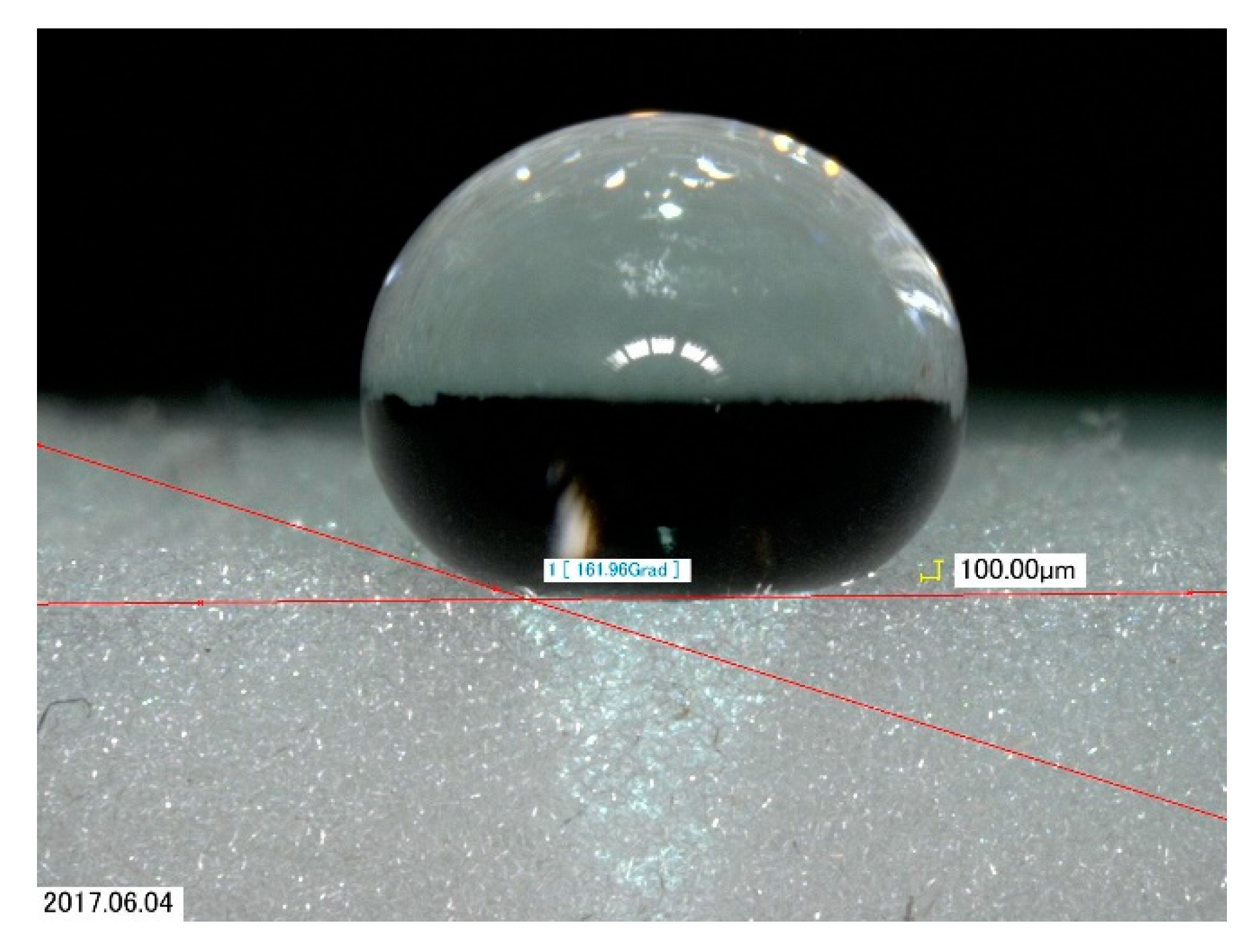
Initially, the superhydrophobic property of the sponge was examined by measuring the contact angle of a water drop on the superhydrophobic sponge.
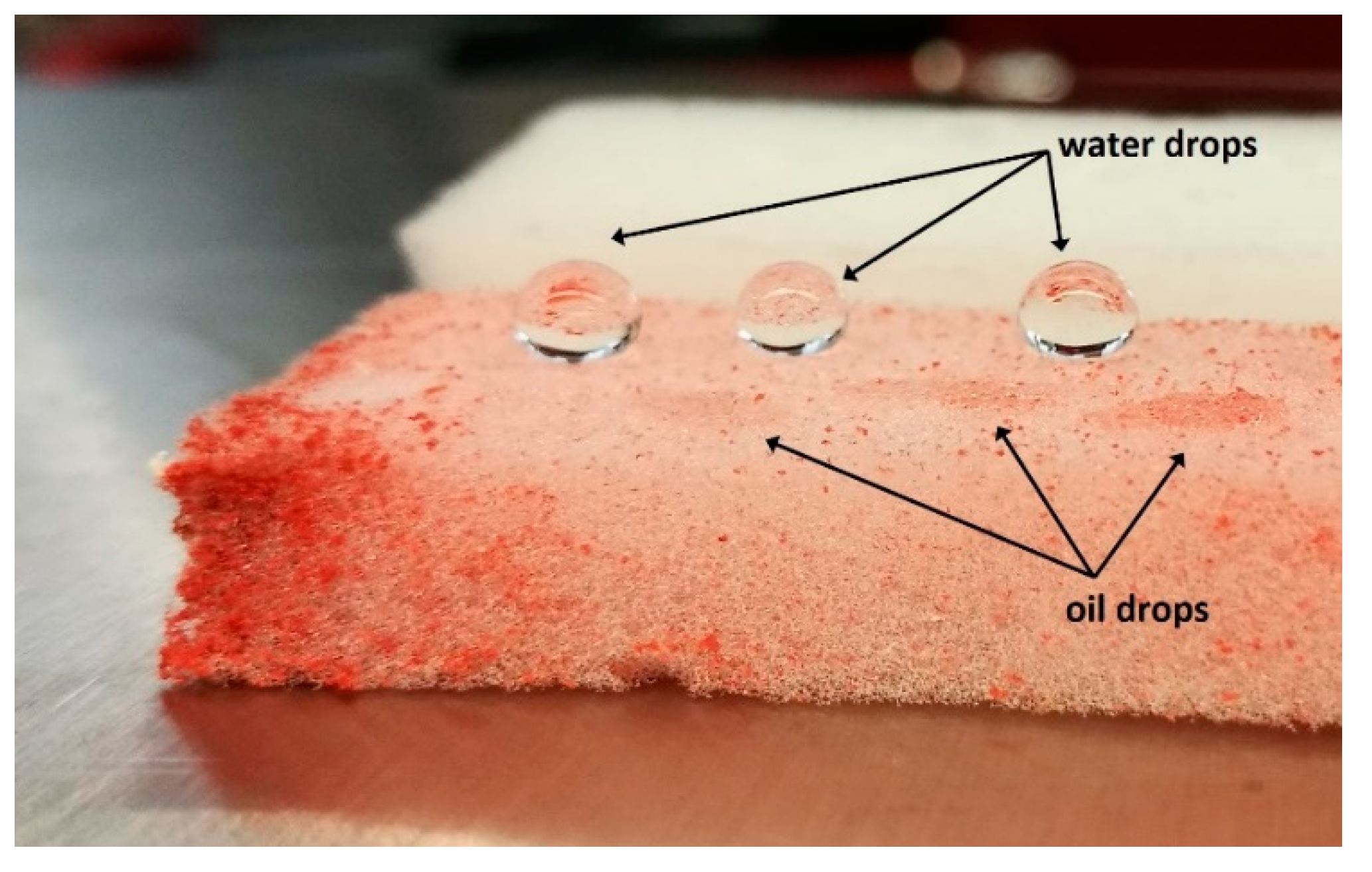
Figure 11 shows the measurement of a water drop on a sponge treated with CAF 1. All measurements revealed a contact angle greater than 160° which proved the superhydrophobic property of the sponge. In order to properly separate the emulsion, the sponge has to show lipophilic behaviour as well. Therefore, to test both properties at once, both oil and water were dropped with a pipette on the sponge.
Figure 12 clearly shows that the three water drops remained on the surface while the tree oil drops were absorbed by the sponge. This behaviour was observed with all produced sponges.
4.4. Emulsion Filtration and Separation
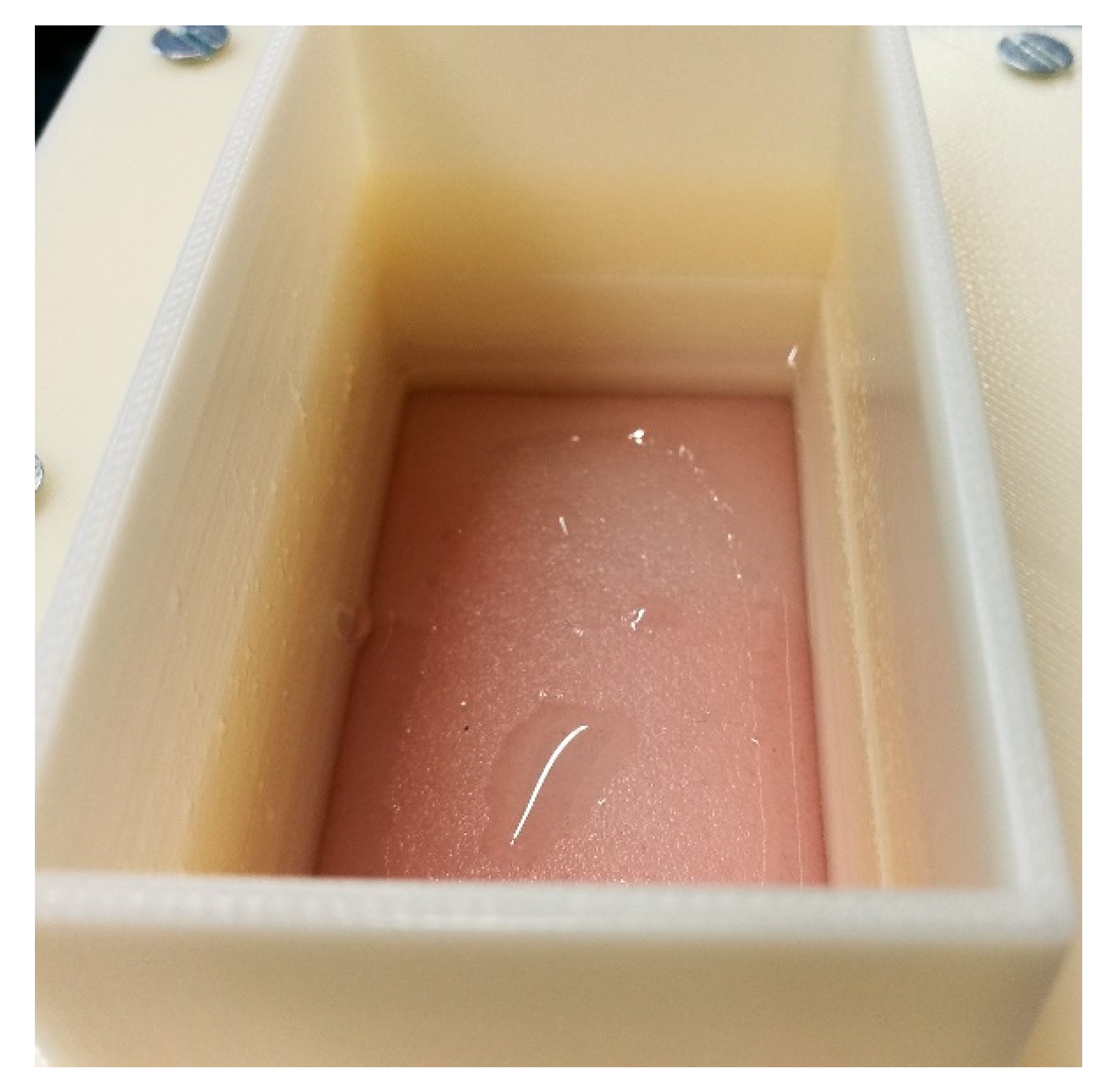
At first, 100 mL of the reproduced emulsion were poured on the filter. Subsequently, 500–1500 mL of emulsion were poured on the filters to further challenge the separation effectiveness. Filters treated with CAF1 and CAF 4 were both able to separate the emulsion, and only transparent oil was seen passing through the filter. The superhydrophobic filter required about 1 min to filtrate 500 mL of the emulsion. After the filtration process, water residues were noticed on top of the filter.
Figure 13 shows the water residue from a 500 mL emulsion on top of the melamine sponge treated with CAF 1. The filtration time for 1500 mL was 5 ½ min.
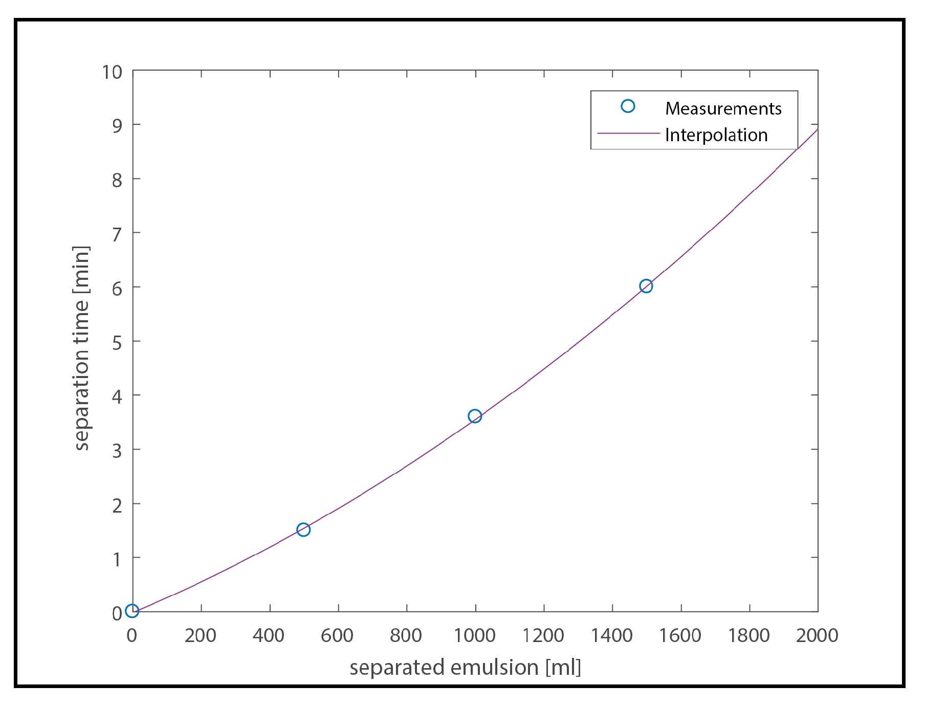
Figure 14 shows the correlation between separation time and amount of emulsion separated by the filter: as it can be seen, there is no linear correlation between the two points, but a seemingly exponential behaviour instead. While such trend would have to be analysed more into details, a reason for the exponentially rising filtration time with increased separated emulsion could be the TBAB water layer, which accumulates on top of the filter without any possibility to escape (see the experimental setup in
Figure 13), hence covering the surface of the filter. As such, the emulsion phase would need an increasing amount of time to reach and pass through the filter itself.
To calculate the permeability of the filter Equations (2) and (3) were used. A permeability of 1,194,980 kg h
−1·m
−2·bar
−1 was calculated. Compared to the permeability of 155,000 L·m
−2·h
−1·bar
−1 reported from Wang et al. [
23], the calculated permeability is around 8 times higher. Such significant difference could be due to the mass ratio of water in the emulsion; in fact, Wang et al. [
23] used a ten times higher mass ratio of the disperse phase. Another reason could be the stability of the emulsion itself. Not only did Wang et al. [
23] use surfactants, they also emulsified their emulsions for longer times (3 h), which could have resulted in more stable emulsions. Furthermore, different variables such as the continuous phase, disperse phase and different adhesives used, could play a role in the differences observed as well.
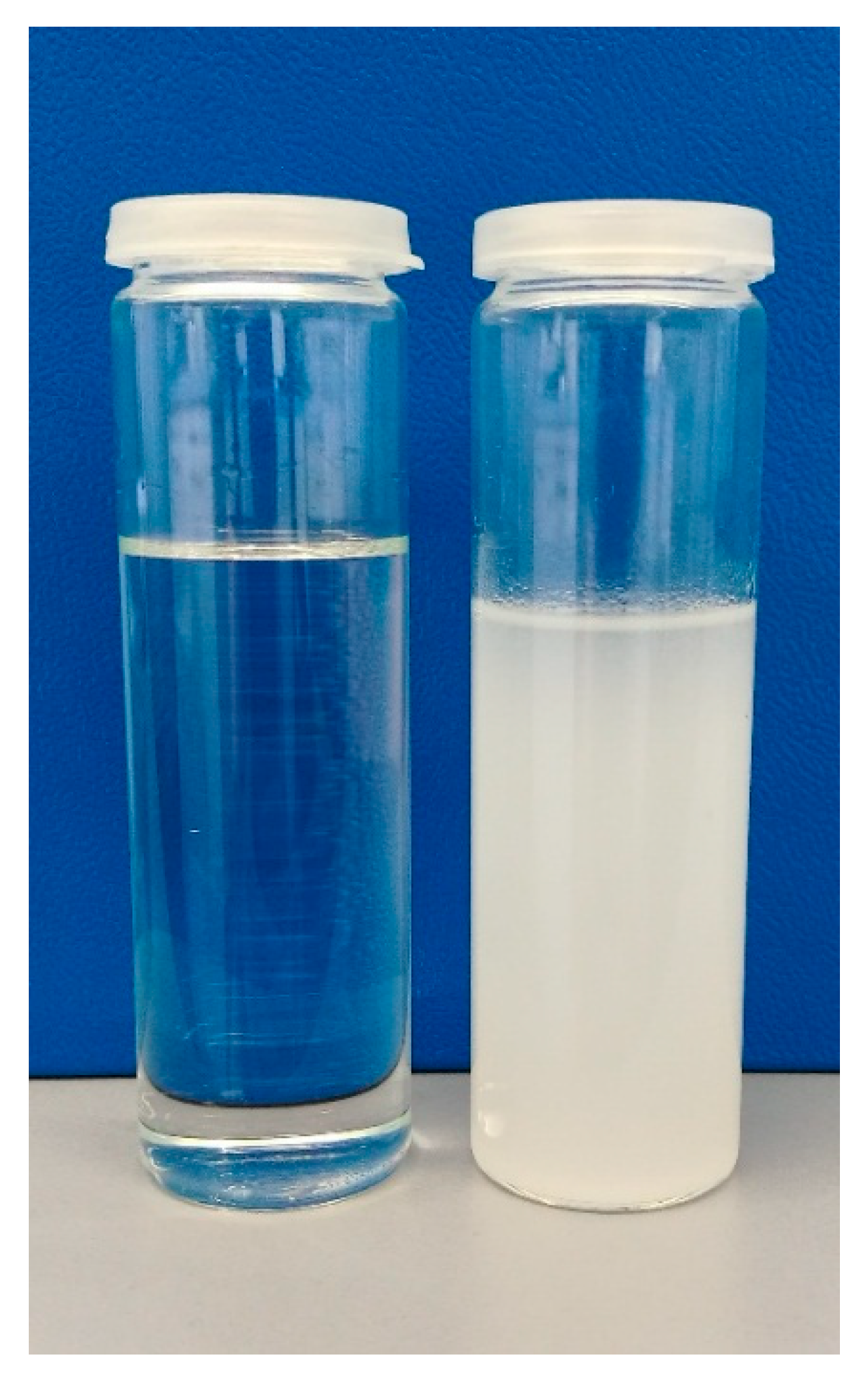
The filtrate was optically analysed for water content with the LUMiSizer
® and as a result only one phase was identified, which indicates the high filtration efficiency of this filter.
Figure 15 shows a photograph of the emulsion and the filtrate taken after the filtration process (additionally, a video of the filtering procedure is available in the
Supplementary Materials section). It can be clearly observed that the clouding of the emulsion has clarified, proving that the two phases have been separated efficiently. Identical results were observed for the filter made with CAF 4.
5. Conclusions
The formation of emulsions between HTF and PCM has been observed in several DCLHS studies and if it is not treated effectively it leads to migration of PCM in the piping system and can result in blockage of the system. The goal of the present study was to develop a system that would allow for the fast separation of a TBAB/water-in-oil emulsion for DCLHS applications. Four different separation methods were considered as a solution for this challenge. Due to low investment and maintenance costs, high separation efficiency and low energy demand, separation with a superhydrophobic melamine sponge was chosen as the most promising method for the problem at hand and was further investigated. The separation efficiency of the filtration system was evaluated under laboratory conditions with emulsions designed to emulate the ones observed in DCLHS setups with TBAB/water as PCM and oil as HTF.
In a first step, samples of emulsions formed in a DCLHS setup with HTF mass flow rates of 30 and 60 kg/h were collected and characterized in terms of mass ratio, demulsification time and drop size distribution. The mass ratio of PCM in the emulsion was an average of wpcm = 0.0135 for all samples tested and was shown to be independent of the mass flow rate of oil in the DCLHS experiments. The separation time of the emulsion was determined to be 50h under normal gravity. Droplets between 2.5 and 10 µm with an arithmetic average of 4.44 µm were observed for the emulsion produced with a 30 kg/h mass flow rate of oil, and drops between 2.5 and 7 µm with an arithmetic average of 4.03 µm for the one produced with 60 kg/h. In a second step, an almost identical emulsion in terms of mass ratio and separation time could be produced in the laboratory by mixing TBAB/water with oil at a rotation speed of 8800 min−1 and adjusting the shear time to 7 s. The artificial emulsion showed broader droplet size distribution between 1 and 15 µm with an arithmetic average of 2.08 µm.
Subsequently melanin sponges with superhydrophobic PDMS adhesive layers were produced to efficiently separate the PCM/oil emulsions. Even though optical observation showed an inhomogeneous accumulation of the adhesive on the filter, a very efficient separation of the emulsions could be shown. A very high permeability (1,194,980 kg·h−1·m−2·bar−1) could be determined. This would result in a small pressure loss over the filter in a real system, and installation in a DCLHS system could be achieved with a minimal increase of energy demand for the pump.
While the method proved to be effective, further studies should examine the influence of the amount and distribution of the adhesive on the separation efficiency, as well as the durability of the superhydrophobic filter. Additionally, it remains uncertain whether the crystallisation process could have an influence on the filter lifetime or the separation efficiency, and as such further investigations would be necessary.
Author Contributions
Conceptualization: L.F., A.S., A.A.; Methodology: S.A., A.A., A.S.; Formal Analysis: S.A.; Investigation: S.A.; Data Curation: S.A.; Writing-Original Draft Preparation: S.A., A.S.; Writing-Review & Editing: A.S., R.R., S.A., J.W.; Visualization: S.A.; Supervision: A.A., A.S., L.F., J.W.; Project Administration: A.S.; Funding Acquisition: A.S., J.W.
Funding
This research was funded by the Swiss National Science Foundation, SNSF grant number [PZENP2_173636] and the Swiss Competence Center for Energy Research Storage of Heat and Electricity (SCCER HaE).
Conflicts of Interest
The authors declare no conflict of interest
References
- Oró, E.; de Gracia, A.; Castell, A.; Farid, M.M.; Cabeza, L.F. Review on phase change materials (PCMs) for cold thermal energy storage applications. Appl. Energy 2012, 99, 513–533. [Google Scholar] [CrossRef]
- Pielichowska, K.; Pielichowski, K. Phase change materials for thermal energy storage. Prog. Mater. Sci. 2014, 65, 67–123. [Google Scholar] [CrossRef]
- Zhou, D.; Zhao, C.Y.; Tian, Y. Review on thermal energy storage with phase change materials (PCMs) in building applications. Appl. Energy 2012, 92, 593–605. [Google Scholar] [CrossRef] [Green Version]
- Sharma, A.; Tyagi, V.V.; Chen, C.R.; Buddhi, D. Review on thermal energy storage with phase change materials and applications. Renew. Sustain. Energy Rev. 2009, 13, 318–345. [Google Scholar] [CrossRef]
- Pereira da Cunha, J.; Eames, P. Thermal energy storage for low and medium temperature applications using phase change materials—A review. Appl. Energy 2016, 177, 227–238. [Google Scholar] [CrossRef] [Green Version]
- Agyenim, F.; Hewitt, N.; Eames, P.; Smyth, M. A review of materials, heat transfer and phase change problem formulation for latent heat thermal energy storage systems (LHTESS). Renew. Sustain. Energy Rev. 2010, 14, 615–628. [Google Scholar] [CrossRef]
- Etherington, T.L. A dynamic heat storage system. Heat. Pip. Air Cond. 1957, 4, 147–151. [Google Scholar]
- Martin, V.; He, B.; Setterwall, F. Direct contact PCM–water cold storage. Appl. Energy 2010, 87, 2652–2659. [Google Scholar] [CrossRef]
- Mehling, H.; Cabeza, L.F. Heat and Cold Storage with PCM; Springer: Berlin/Heidelberg, Germany, 2008; ISBN 978-3-642-08807-0. [Google Scholar]
- Nomura, T.; Tsubota, M.; Oya, T.; Okinaka, N.; Akiyama, T. Heat storage in direct-contact heat exchanger with phase change material. Appl. Therm. Eng. 2013, 50, 26–34. [Google Scholar] [CrossRef]
- Nomura, T.; Tsubota, M.; Oya, T.; Okinaka, N.; Akiyama, T. Heat release performance of direct-contact heat exchanger with erythritol as phase change material. Appl. Therm. Eng. 2013, 61, 28–35. [Google Scholar] [CrossRef]
- Farid, M.M.; Khudhair, A.M.; Razack, S.A.K.; Al-Hallaj, S. A review on phase change energy storage: Materials and applications. Energy Convers. Manag. 2004, 45, 1597–1615. [Google Scholar] [CrossRef]
- Nomura, T.; Tsubota, M.; Sagara, A.; Okinaka, N.; Akiyama, T. Performance analysis of heat storage of direct-contact heat exchanger with phase-change material. Appl. Therm. Eng. 2013, 58, 108–113. [Google Scholar] [CrossRef]
- Kiatsiriroat, T.; Tiansuwan, J.; Suparos, T.; Na Thalang, K. Performance analysis of a direct-contact thermal energy storage-solidification. Renew. Energy 2000, 20, 195–206. [Google Scholar] [CrossRef]
- Stockerl, R. Dynamic Investigations of the Recrystallization of Incongruently Melting Salt Hydrates Using the Example of Glauber’s Salt. Ph.D. Thesis, University of Regensburg, Regensburg, Germany, 1988. [Google Scholar]
- Ammann, A. Aufbau, Inbetriebnahme und Messungen an einem Latentwärmespeicher mit Direktkontakt-Wärmeübertragung. Master‘s Thesis, Hochschule Luzern HSLU, Lucerne, Switzerlan, 2017. [Google Scholar]
- Lindner, F. Die Entwicklung Eines Dynamischen Glaubersaltz-Latentwärmespeichers bis zur Serienreife; Research Report DFVLR-FB 81-32; Deutsche Forschung- und Versuchsanstalt für Luft- und Raumfahrt: Stuttgard, Germany, 1981. [Google Scholar]
- Krimmel, S.; Ammann, A.; Ludger, J.F.; Stamatiou, A.; Worlitschek, J. Investigation of Direct Contact Heat Exchange for High Thermal Power Latent Heat Storage. In Proceeding of the 14th International Conference on Energy Storage (EnerSTOCK2018), Adana, Turkey, 25–28 April 2018. [Google Scholar]
- Jones, T.J.; Neustadter, E.L.; Whittingham, K.P. Water-in-Crude Oil Emulsion Stability and Emulsion Destabilization By Chemical Demulsifiers. J. Can. Pet. Technol. 1978, 17, 100–108. [Google Scholar] [CrossRef]
- Kocherginsky, N.M.; Tan, C.L.; Lu, W.F. Demulsification of water-in-oil emulsions via filtration through a hydrophilic polymer membrane. J. Membr. Sci. 2003, 220, 117–128. [Google Scholar] [CrossRef]
- Sun, D.; Duan, X.; Li, W.; Zhou, D. Demulsification of water-in-oil emulsion by using porous glass membrane. J. Membr. Sci. 1998, 146, 65–72. [Google Scholar] [CrossRef]
- Huang, X.; Lim, T.T. Performance and mechanism of a hydrophobic-oleophilic kapok filter for oil/water separation. Desalination 2006, 190, 295–307. [Google Scholar] [CrossRef]
- Wang, C.F.; Chen, L.T. Preparation of Superwetting Porous Materials for Ultrafast Separation of Water-in-Oil Emulsions. Langmuir 2017, 33, 1969–1973. [Google Scholar] [CrossRef] [PubMed]
- Su, X.; Li, H.; Lai, X.; Zhang, L.; Wang, J.; Liao, X.; Zeng, X. Vapor-Liquid Sol-Gel Approach to Fabricating Highly Durable and Robust Superhydrophobic Polydimethylsiloxane@Silica Surface on Polyester Textile for Oil-Water Separation. ACS Appl. Mater. Interfaces 2017, 9. [Google Scholar] [CrossRef] [PubMed]
- Jeon, S.B.; Kim, D.; Yoon, G.W.; Yoon, J.B.; Choi, Y.K. Self-cleaning hybrid energy harvester to generate power from raindrop and sunlight. Nano Energy 2015, 12, 636–645. [Google Scholar] [CrossRef]
- Fürstner, R.; Barthlott, W.; Neinhuis, C.; Walzel, P. Wetting and self-cleaning properties of artificial superhydrophobic surfaces. Langmuir 2005, 21, 956–961. [Google Scholar] [CrossRef] [PubMed]
- Zhang, X.; Shi, F.; Niu, J.; Jiang, Y.; Wang, Z. Superhydrophobic surfaces: From structural control to functional application. J. Mater. Chem. 2008, 18, 621–633. [Google Scholar] [CrossRef]
- Chen, Q.; de Leon, A.; Advincula, R.C. Inorganic−Organic Thiol-ene Coated Mesh for oil/water separation. ACS Appl. Mater. Interfaces 2015, 7, 18566–18573. [Google Scholar] [CrossRef] [PubMed]
- Feng, L.; Zhang, Z.; Mai, Z.; Ma, Y.; Liu, B.; Jiang, L.; Zhu, D. A super-hydrophobic and super-oleophilic coating mesh film for the separation of oil and water. Angew. Chem. Int. Ed. 2004, 43, 2012–2014. [Google Scholar] [CrossRef] [PubMed]
- Gomes, D.J.C.; De Souza, N.C.; Silva, J.R. Using a monocular optical microscope to assemble a wetting contact angle analyser. Meas. J. Int. Meas. Confed. 2013, 46, 3623–3627. [Google Scholar] [CrossRef]
- Detloff, T.; Sobisch, T.; Lerche, D. Particle size distribution by space or time dependent extinction profiles obtained by analytical centrifugation (concentrated systems). Powder Technol. 2007, 174, 50–55. [Google Scholar] [CrossRef]
- Fischer, L.J.; von Arx, S.; Wechsler, U.; Züst, S.; Worlitschek, J. Phase change dispersion, potentially a new class of heat transfer fluids. J. Phys. Conf. Ser. 2016, 745. [Google Scholar] [CrossRef]
Figure 1.
Different contact angles θ of a drop on a surface. If θ < 90°, the surface is called hydrophilic. Conversely, when θ > 90° the surface is hydrophobic, and when θ > 150° it is defined as superhydrophobic.
Figure 1.
Different contact angles θ of a drop on a surface. If θ < 90°, the surface is called hydrophilic. Conversely, when θ > 90° the surface is hydrophobic, and when θ > 150° it is defined as superhydrophobic.
Figure 2.
Schematic of the DCLHS system used at Lucerne University of Applied Sciences and Arts Reproduced with permission from [
16], Ammann, A. Aufbau, Inbetriebnahme und Messungen an einem Latentwärmespeicher mit Direktkontakt-Wärmeübertragung. Master‘s Thesis, Hochschule Luzern HSLU, Lucerne, Switzerlan, 2017.
Figure 3.
Expanded melamine sponge after compressed curing.
Figure 3.
Expanded melamine sponge after compressed curing.
Figure 4.
Rendered graphical representation of the f holder (in green and grey) used to fix the filter (in red) during the filtration process.
Figure 4.
Rendered graphical representation of the f holder (in green and grey) used to fix the filter (in red) during the filtration process.
Figure 5.
Instability index of the two artificial laboratory emulsions. Average from six measurements.
Figure 5.
Instability index of the two artificial laboratory emulsions. Average from six measurements.
Figure 6.
(a) drop size distribution of the laboratory emulsion 30 kg/h; (b) drop size distribution of laboratory emulsion 60 kg/h.
Figure 6.
(a) drop size distribution of the laboratory emulsion 30 kg/h; (b) drop size distribution of laboratory emulsion 60 kg/h.
Figure 7.
Instability index of the two laboratory emulsions and the reproduction emulsion with a shear time of 7 s.
Figure 7.
Instability index of the two laboratory emulsions and the reproduction emulsion with a shear time of 7 s.
Figure 8.
Drop size distribution of the reproduced emulsion with a shear time of 7 s.
Figure 8.
Drop size distribution of the reproduced emulsion with a shear time of 7 s.
Figure 9.
Top side of a melamine sponge treated with CAF 1. Several spots with higher concentration of CAF1 could be observed (stronger red colour).
Figure 9.
Top side of a melamine sponge treated with CAF 1. Several spots with higher concentration of CAF1 could be observed (stronger red colour).
Figure 10.
(a) topside (left) and bottom side (right) of a melamine sponge treated with CAF1 and (b) Sectional view of the superhydrophobic porous material.
Figure 10.
(a) topside (left) and bottom side (right) of a melamine sponge treated with CAF1 and (b) Sectional view of the superhydrophobic porous material.
Figure 11.
Contact angle measurement of a water drop on the superhydrophobic filter.
Figure 11.
Contact angle measurement of a water drop on the superhydrophobic filter.
Figure 12.
Water drops and absorbed oil drops on superhydrophobic filter.
Figure 12.
Water drops and absorbed oil drops on superhydrophobic filter.
Figure 13.
Water residue on top of the CAF1 filter after filtration of 500 mL emulsion.
Figure 13.
Water residue on top of the CAF1 filter after filtration of 500 mL emulsion.
Figure 14.
Correlation between the separation time and amount of emulsion separated. An exponential behaviour is observed. Such trend is thought to be due to the impossibility of the water/TBAB layer to escape the filter, therefore covering its surface and increasing the time the oil phase needs to reach the surface.
Figure 15.
Photograph of artificial emulsion before the filtration (right) and filtrate (left) using a superhydrophobic filter.
Figure 15.
Photograph of artificial emulsion before the filtration (right) and filtrate (left) using a superhydrophobic filter.
Table 1.
Evaluation of the four different concepts. The concepts are rated on a scale from one to six in seven different categories. The highest value being six, and the lowest 1. A maximal total of 42 can be reached for each separation technique. As it can be observed, thanks to low energy demand, low costs of maintenance and investment, superhydrophobic filters score the highest grade in the table, therefore being the most suitable technique for this research purposes.
| Criteria | Hydrophilic Glass Membrane | Concepts Superhydrophobic Filter | Centrifuge | Demulsifier |
|---|
| Separation efficiency | 4 | 5 | 6 | 3 |
| System integration | 5 | 5 | 6 | 6 |
| Lifetime | 3 | 3 | 6 | 3 |
| Maintenance | 6 | 6 | 2 | 3 |
| Energy demand | 4 | 5 | 1 | 4 |
| Procurement effort/manufacturing effort | 4 | 3 | 5 | 4 |
| Investment costs | 4 | 6 | 1 | 4 |
| Total | 30 | 33 | 27 | 27 |
© 2018 by the authors. Licensee MDPI, Basel, Switzerland. This article is an open access article distributed under the terms and conditions of the Creative Commons Attribution (CC BY) license (http://creativecommons.org/licenses/by/4.0/).


 ,
, 


