The following sub-sections contain simulation results for the electro-hydraulic modelling and results.
4.1. Modelling
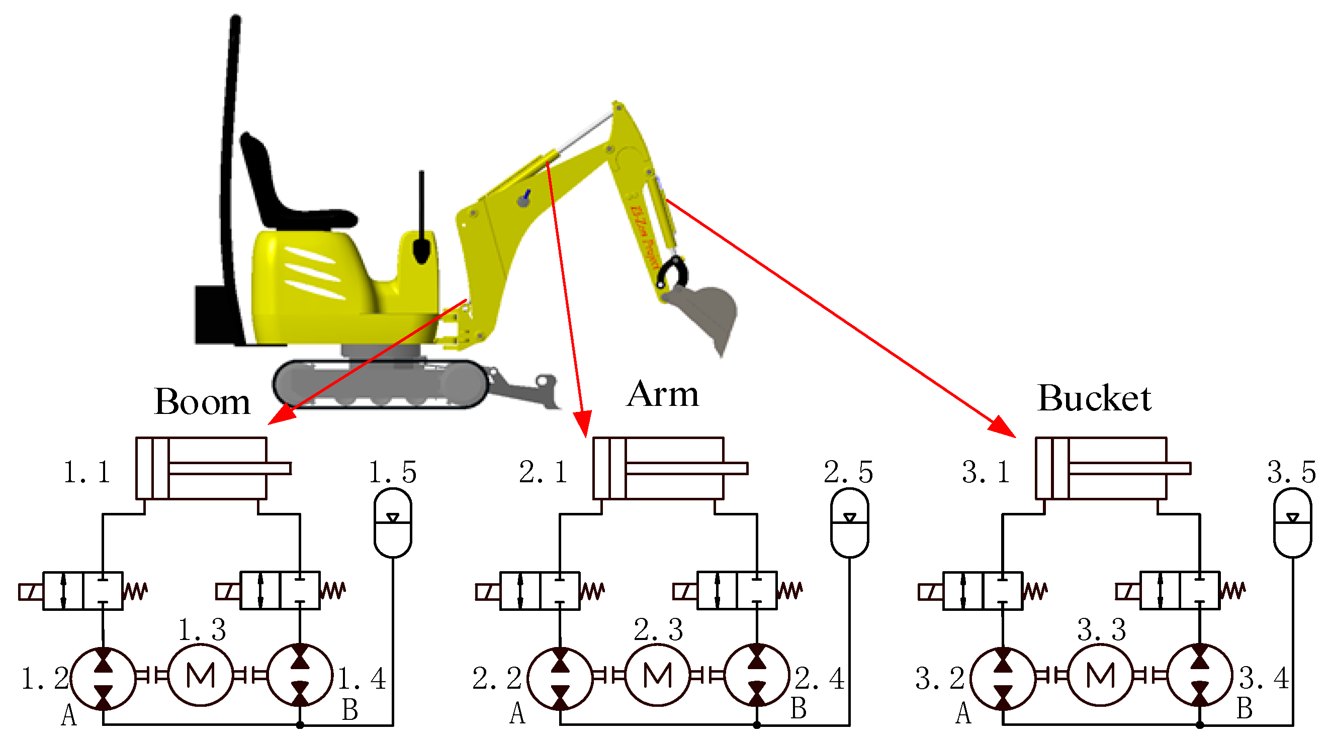
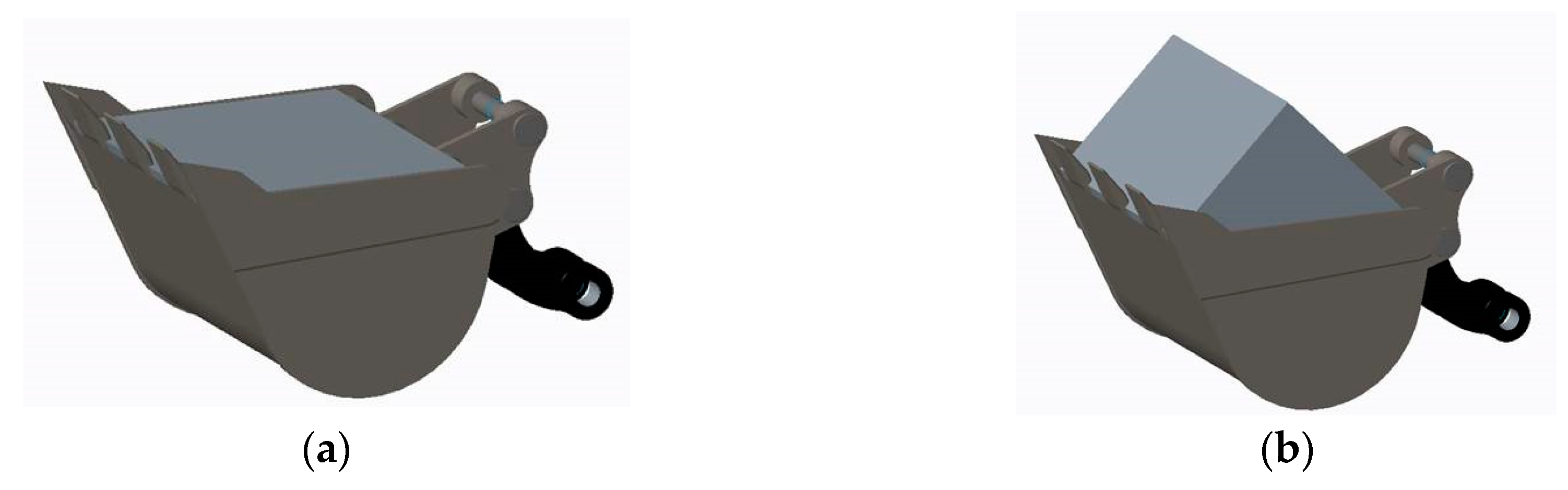
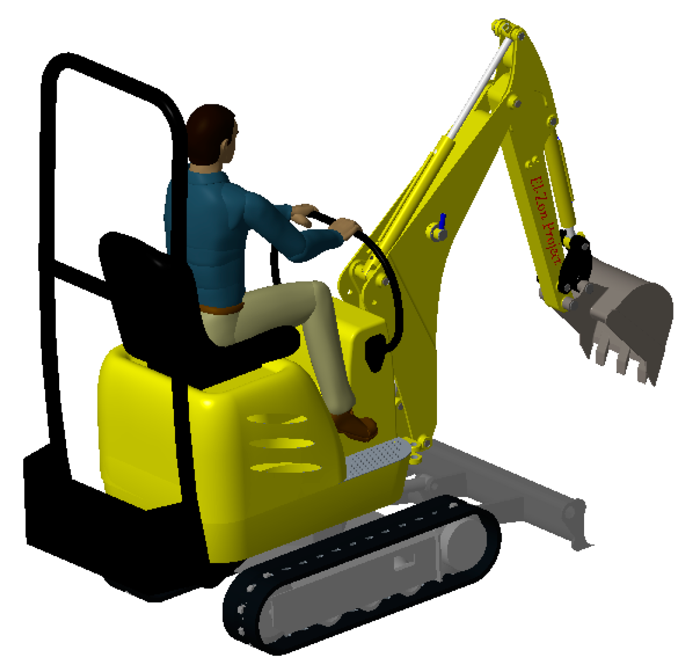
The model of the excavator consists of the mechanical model (with or without DDH units) coupled with electro-hydraulics models. The 3D solid mechanical model of the excavator was constructed in Creo 3.0. The weight of the excavator part was measured, and material was assigned to each part in the Creo program to match the measured weight. The 3D model of each DDH unit was built and weight of DDH unit is estimated to be 29 kg. The multibody dynamic model with and without DDH units was exported from Creo and imported into MATLAB (R2016b, MathWorks, Natick, MA, USA) Simscape using the Simscape Multibody Link Plug-In.
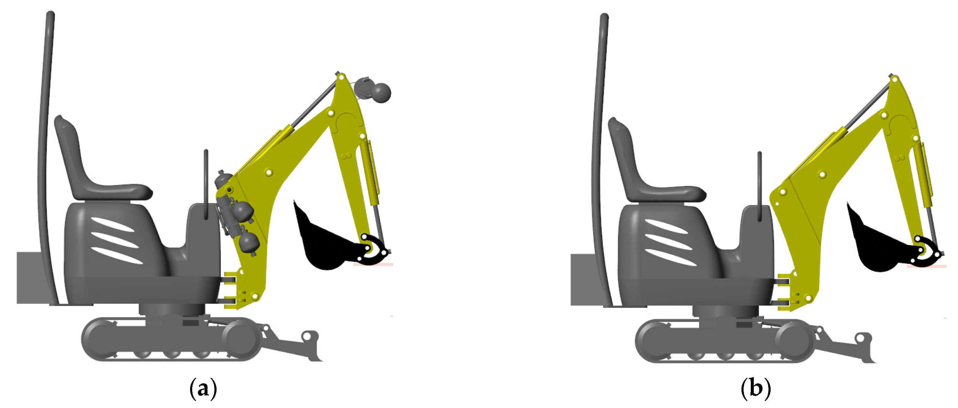
Figure 15 presents the mechanical model with and without the DDH units.
As components of DDH, the cylinder, pump/motor, accumulator, and pipe are realized in the MATLAB/Simulink environment. Most of their detailed explanations refer to work in [
28]. In addition, further improvements to the model were performed. Switching between motoring and pumping mode was added. This improved pump modelling significantly. The leakage models of pumps—external bi-directional gear motors by Hydac—were updated with the analytical method [
29]. The hose model was updated with a pressure drop. The overall model is considered to be reliable, as it was validated in early studies in [
16]; and in addition, the cylinder friction was validated with a micro-excavator [
30].
Following section introduces utilized analytical model the pump/motor. The overall leakage flow rate and friction torque depend on the pressure differential over the pump/motor.
The leakage flow rate is given in Equation (1):
and the friction torque is as shown in Equation (2):
where
KHP is the Hagen-Poiseuille coefficient for laminar pipe flows, and
KTP is the friction torque vs the pressure gain coefficient,
τ0 is the no-load torque, and
ωThresh is the threshold angular velocity for the pump-motor transition.
The Hagen-Poiseuille and the friction torque coefficients are determined from nominal fluid and component parameters through the Equations (3) and (4):
where
νNom and
ρNom are the nominal kinematic viscosity and fluid density of the fluid.
ωNom and Δ
pNom are the nominal shaft angular velocity and the pressure difference of the pump/motor, respectively.
ηv,Nom is the volumetric efficiency at nominal conditions.
v and
ρ are the actual density and kinematic viscosity of the fluid. The volumetric efficiencies
ηv,Nom and the hydro-mechanical efficiencies of the selected motors are extracted and calculated based on the curves in the datasheet by Hydac, which contain the flow and torque varying with speed at nominal pressure.
Table 5 illustrates parameters of the pump/motor provided by manufacturer (Hydac).
In order to look into the energy efficiency effect of the extra weight produced by DDH units on the front attachment of the excavator, the simulation adopting different cycles are done with and without this extra weight of DDH units. The following subsection introduces the results of the simulation study and their analyses.
4.2. Results
The power of cylinder is calculated by the product of the hydraulic force and the velocity of the cylinder, including the friction effect, as given in Equation (5):
where the
pA and
pB are the pressures in the piston (A) and rod (B) chambers of the cylinder;
AA and
AB are the effective areas in the A and B chambers of the cylinder; and
x is the displacement of the piston.
Pump A or pump B is running in pumping mode when the product of the pressure difference over the pump and its angular velocity is positive, and running in motoring mode when this product is negative, as shown in Equation (6):
where
Ppump,
Vpump, and
ηhm,pump are the power, the displacement, and the hydromechanical efficiency of the pump, respectively.
The power of the electrical motor was computed by using the sum power of pump A and pump B divided by its efficiency, as given in Equation (7):
where
PApump and
PBpump are the powers of pumps A and B in a DDH unit, ω is the angular velocity of the shaft connecting pumps and the electric motor, and
Pe-motor and
ηe-motor are the power and efficiency of the electric motor.
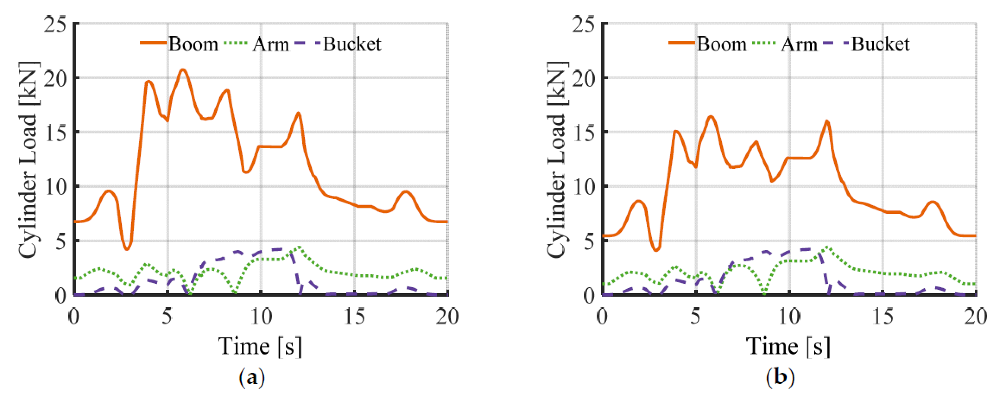
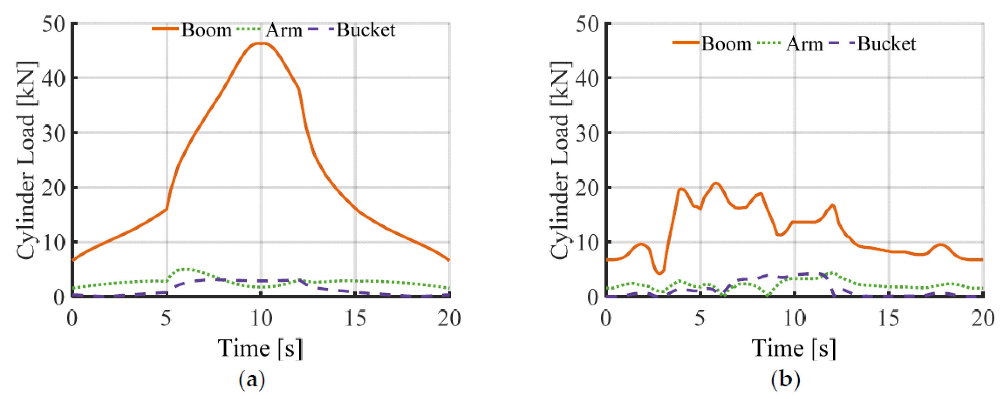
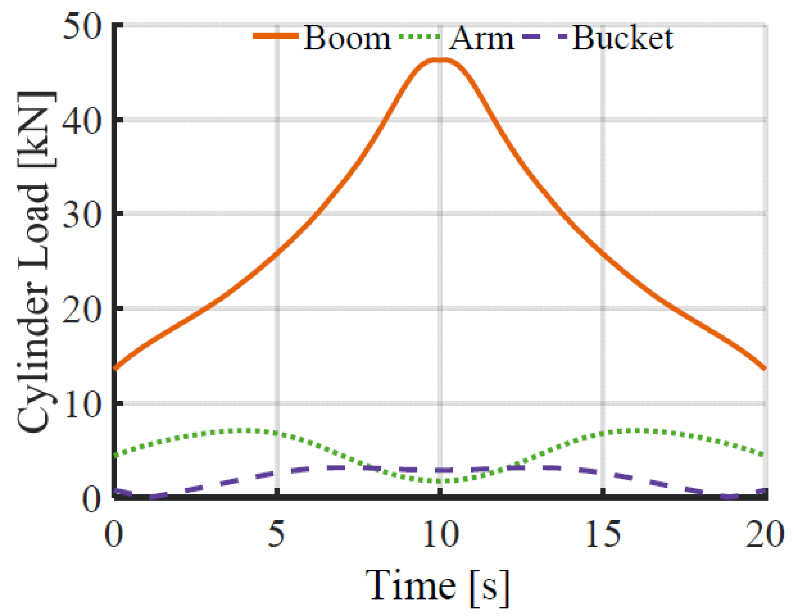
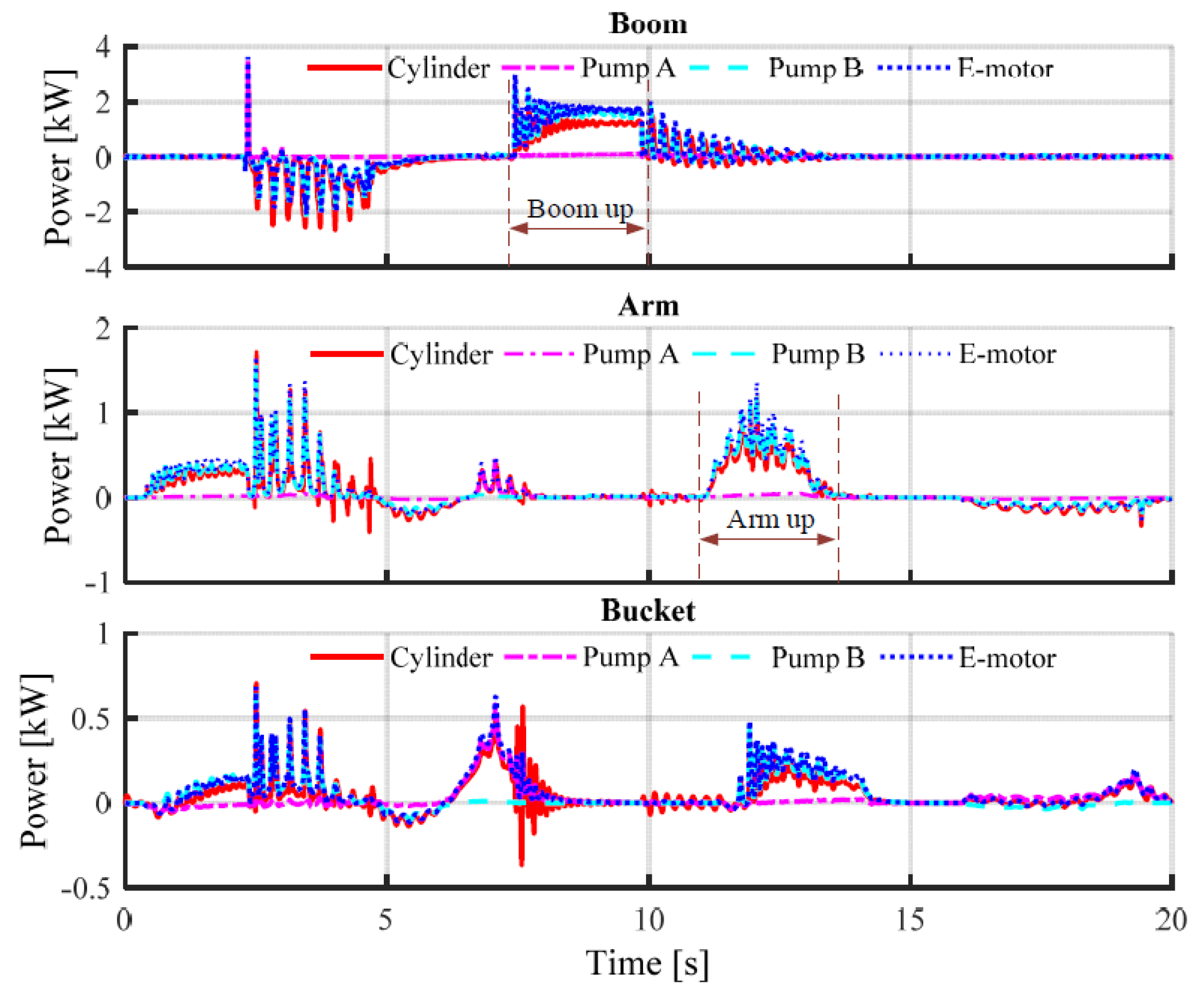
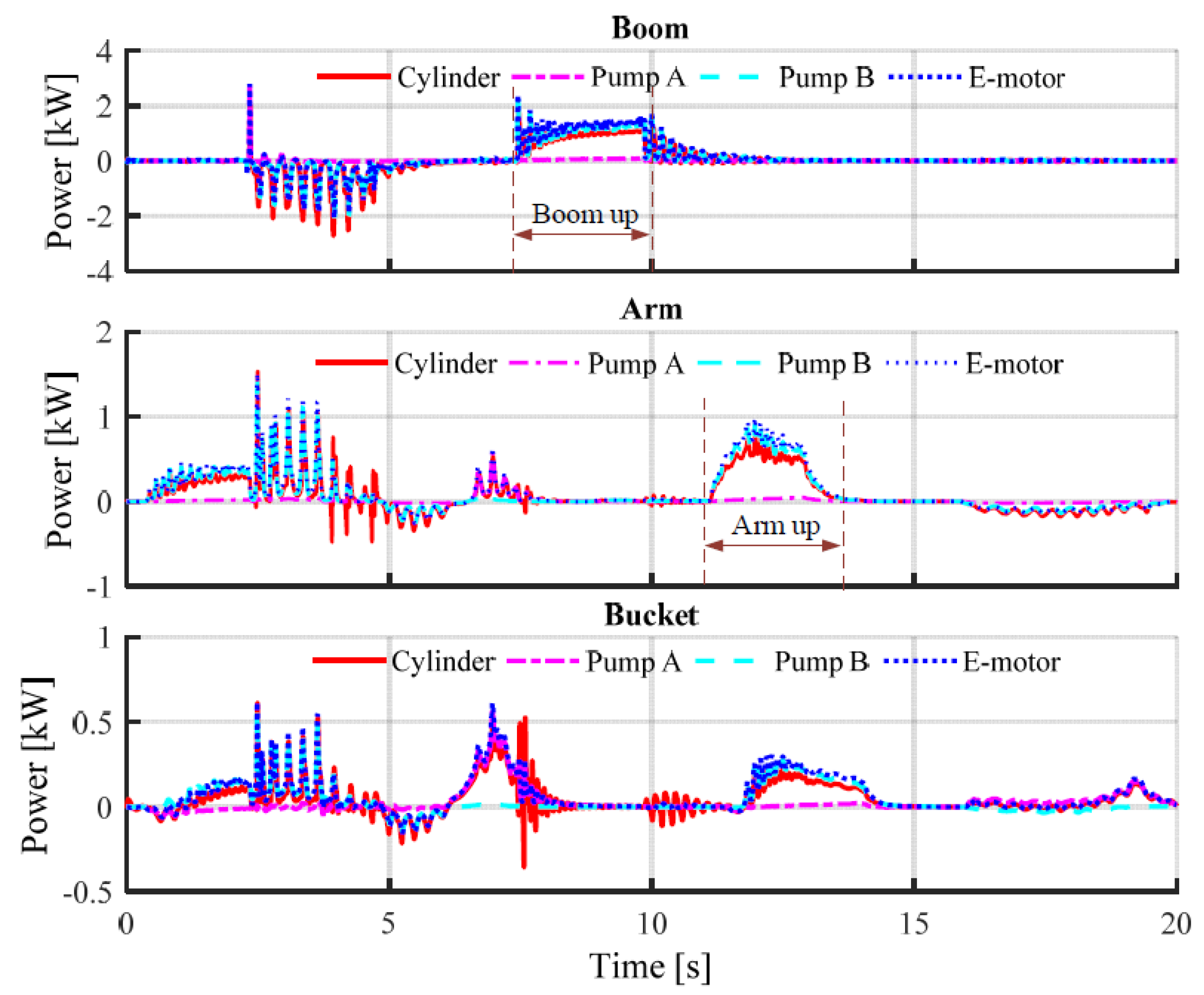
Figure 16 and
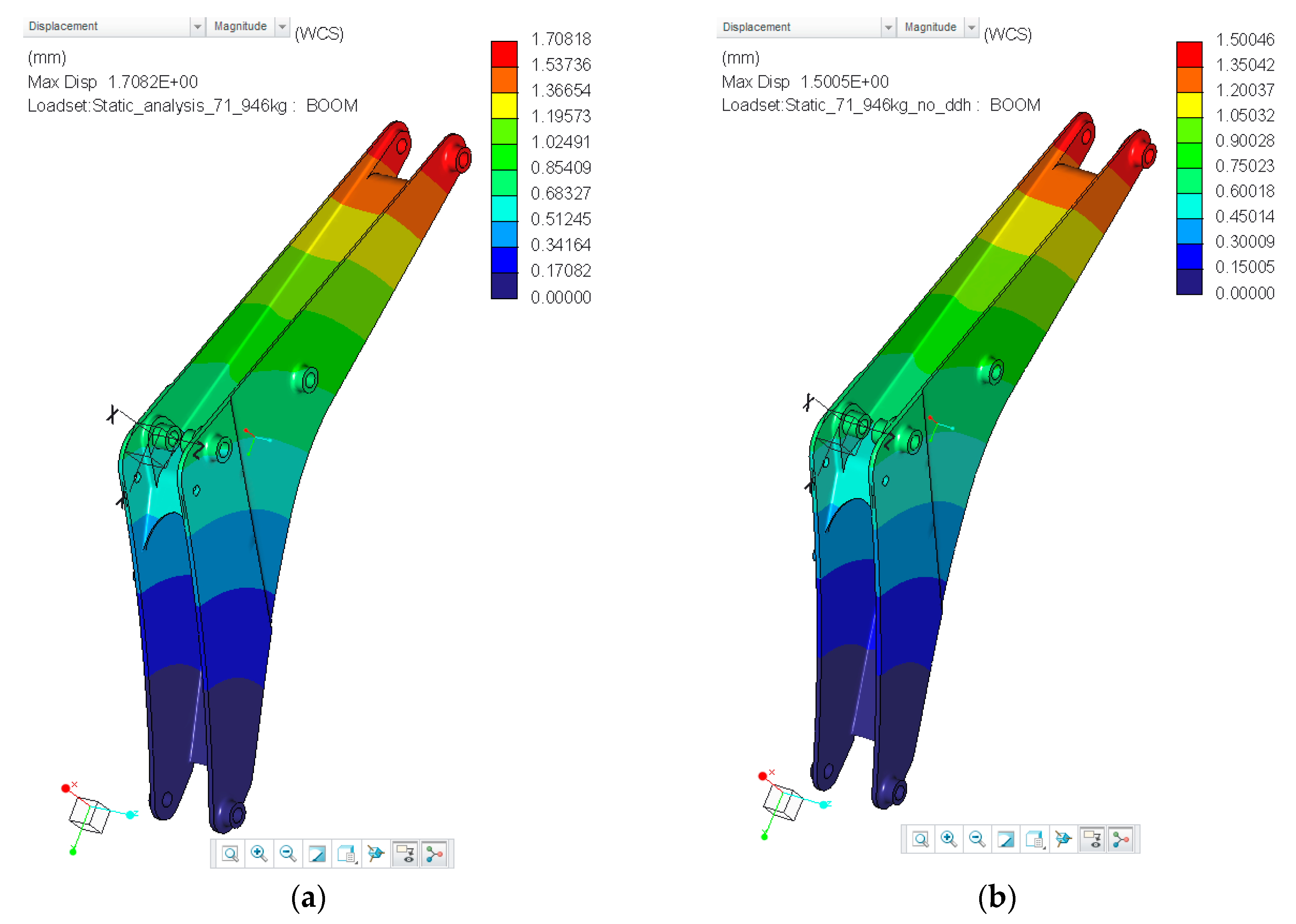
Figure 17 illustrate the power distribution of each cylinder and for the typical digging cycle with and without the extra weight of DDH units. Comparing
Figure 16 and
Figure 17 reveals a slight variation in power requirements for systems with and without the extra weight of DDH units. During the boom up in the typical digging cycle, the mean powers demanded by the electric motor of boom DDH are 1.6 kW and 1.1 kW for considering and ignoring the weight of the DDH units. Additionally, the peak power of the boom electric motor during the boom up are 3.0 kW and 2.4 kW, respectively. The power distribution of bucket DDH does not change due to no DDH being installed on the bucket.
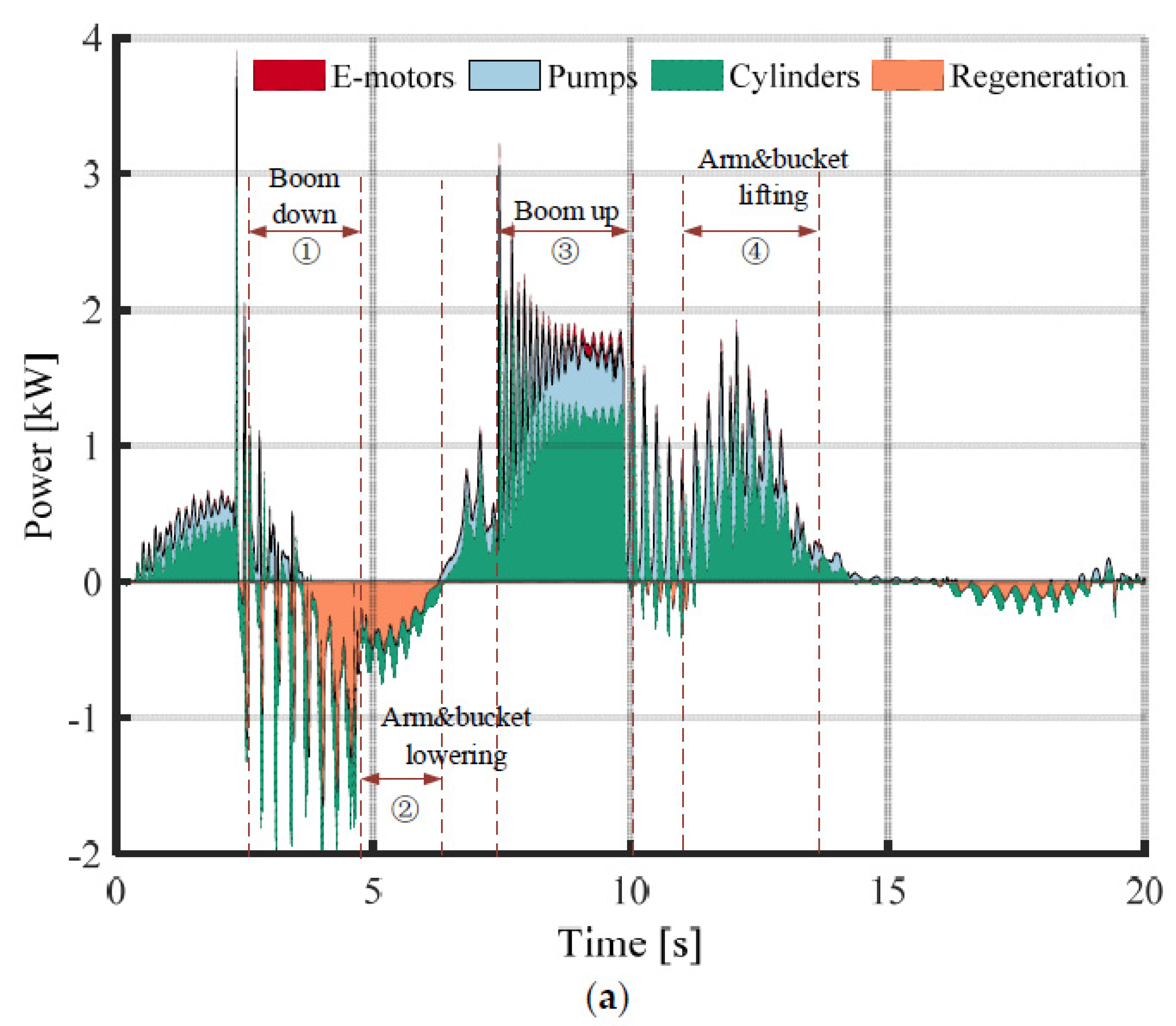
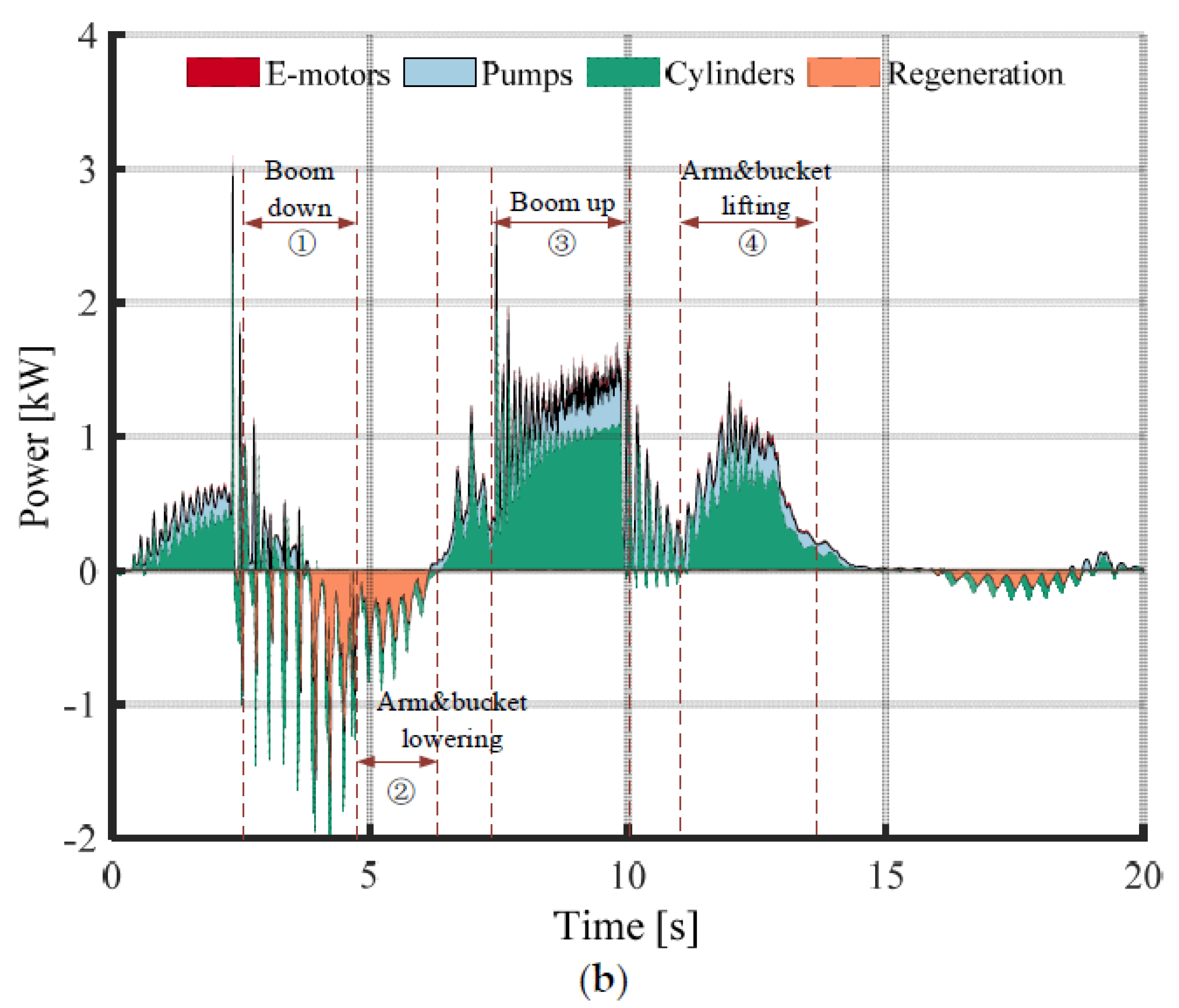
Figure 18 presents the overall power distributions of cylinders, pumps, electric motors, and regeneration in the typical digging cycle. When the power of the cylinders is positive, it means the system is consuming electric power.
In contrast, the system converts the potential and kinetic energy into electric power. The extra weight of DDH units mainly affects the consuming and the regenerating power of the boom and arm DDH units, but not the bucket. Phases 1 and 2 in
Figure 18a,b demonstrate the possibility of energy regeneration and the regeneration power slightly increasing during boom down and arm & bucket lowering. During the boom up and arm & bucket lifting, phases 3 and 4 show that the more power demanded by the system grows due to the extra weight of the DDH units.
The overall regeneration energy
EReg and energy consumption
EDDHs of DDH units are computed by integrating the negative and positive part of the power of the electric motors, as shown in Equations (8) and (9):
where
Pcylinders and
Pe-motors are the powers of the three cylinders and three electric motors, and
t1 and
t2 are the start and end time of the working cycle.
Without considering the regeneration possibility of the DDH units, the overall energy efficiency
ηDDHs is calculated with the integration of the positive power of a cylinder (including the friction effect) divided by the integration of the positive power into electric motors, as shown in Equation (10). In addition, the regeneration efficiency of DDH units is computed with the integration of the negative power of the electric motors divided by the integration of the negative power of the cylinders, as shown in Equation (11):
Table 6 illustrates the energy consumption and efficiency analysis results, including three varying cycles: typical digging cycles, modified Japanese digging cycle, and levelling cycle.
The results show that the energy consumption is approximately 15% (15.4%, 18.9%, and 13.5%) higher, with extra weight produced by the three DDH units for the typical digging cycle, JCMAS digging and leveling cycle. Although approximately 20% (26.3%, 22.6%, and 18.2%) more regeneration energy is produced, taking into account the regeneration energy, the increases in energy consumption are 12.2%, 17.2%, and 11.1%. For the selected working cycle, the energy consumption with the added weight of DDH units is higher, and the same time regenerative energy is also higher compared to the system without added weight.


