Design Issues for Claw Pole Machines with Soft Magnetic Composite Cores
by
 , , and
Chengcheng Liu
1,2 ,
,
Jiawei Lu
1,2,
Youhua Wang
1,2,*,
Gang Lei
3 ,
,
Jianguo Zhu
4 and
and
Youguang Guo
3 1
State Key Laboratory of Reliability and Intelligence of Electrical Equipment, School of Electrical Engineering, Hebei University of Technology, Tianjin 300130, China
2
Key Laboratory of Electromagnetic Field and Electrical Apparatus Reliability of Hebei Province, School of Electrical Engineering, Hebei University of Technology, Tianjin 300130, China
3
School of Electrical and Data Engineering, University of Technology Sydney, Ultimo, NSW 2007, Australia
4
School of Electrical and Information Engineering, University of Sydney, Ultimo, NSW 2007, Australia
*
Author to whom correspondence should be addressed.
Energies 2018, 11(8), 1998; https://doi.org/10.3390/en11081998
Submission received: 17 July 2018
/
Revised: 26 July 2018
/
Accepted: 28 July 2018
/
Published: 1 August 2018
(This article belongs to the Section I: Energy Fundamentals and Conversion)
Abstract
:By using global ring winding, the torque coefficient of the transverse flux machine (TFM) is proportional to its number of pole pairs, and thus the TFM possesses high torque density ability when compared with other electrical machines. As a special kind of TFM, the claw pole machine (CPM) can have more torque due to its special claw pole teeth. The manufacturing of CPM or TFM with silicon steels was very difficult in the past, and is a handicap for the progress of this kind of machine. Thanks to the advent of soft magnetic composite (SMC) materials, the manufacturing process of CPM has become more and more simple. More attention has been paid to this kind of technology, and some mass production CPMs with SMC cores have appeared. However, there are few works that discuss the key design issues for this kind of machine. In this paper, a small CPM with SMC is used as as a research benchmark. Various design methods that can be adopted to improve its performance have been studied, including unequal stator claw pole teeth, a skewing magnet design, consequent pole design, and etc. The 3D finite element method (FEM) is used for the machine analysis, and it is verified by the experimental results of a CPM with SMC cores.
1. Introduction
The massive development of green energy devices, such as the electric vehicle, has generated great interest in high-performance electrical machines [1]. Due to the adopted use of global ring winding, the torque coefficient of a transverse flux machine (TFM) is proportional to its number of pole pairs, and thus the torque density of TFM is higher than the other electrical machines [2,3,4,5,6]. The concept of TFM was is first proposed in 1885 by W.M. Morday. It gained more attention in the late 1980s after it was reintroduced by Weh et al. [7]. The major merit of TFM is its high torque ability, and no coupling between the adjacent modules compared with the radial flux machine and axial flux machine. In the last decades, various kinds of TFM were developed for high-performance drive applications, especially the direct drive applications [8,9,10]. The claw pole machine (CPM) is a special kind of TFM; it can have better performance compared with TFM, as the stator claw pole teeth is introduced for utilizing the space magnetic field. However, the main problem is the manufacturing process, as it handicaps the development of TFM and CPM, as silicon steels needs to be used for designing the 3D magnetic flux structure stator core [11].
Soft magnetic composite (SMC) materials are a new kind of soft magnetic material. They are composed of surface electrically insulated iron powder particles, which result in low eddy current loss, magnetic isotropy, and thermal isotropy [12,13,14,15]. By using powder metallurgy technology, various complex structures of the stator core can be manufactured without the need for any additional machining processes. Compared with other soft magnetic materials, SMCs can have great of advantages (e.g., low eddy current loss, low manufacturing cost, etc.). With the adoption of SMC materials the manufacturing of CPM will be much easier. In past decades, the developed SMC machines and especially the TFM with SMC cores were very hot and some design guidelines have since been recorded for the design of SMC machines [16,17,18]. Some mass-production SMC machines can be bought as well.
However, few studies have been done for the systematic investigation of CPM with SMC cores. In this paper, an inner rotor CPM is set as the research target, and unequal stator claw pole teeth, a skewing magnet design, a consequent pole design are investigated. In the design of CPM, the stator wall thickness, stator inner radius, gap length between adjacent phase module, and the adopted materials are fully investigated. For the performance calculation, the 3-D finite element method (FEM) software MAXWELL 3D is used, and the effectiveness of the calculation is verified by experiment results on the research target. Finally, the key design issues will be concluded.
2. Topology of the Claw Pole Machine
Figure 1 illustrates the topology of the initial CPM with SMC cores, which is a single phase model. The complete machine is composed of three single-phase models, which are stacked axially with a determined shifting angle of 120° electrically. Each stator of the single phase CPM is composed of two separate SMC stator cores, and the global winding is placed between them. The magnets are surface mounted onto the rotor cores. The torque coefficient of the CPM is proportional to its number of pole pairs. However, the high number of pole pairs will cause the machine to have high flux leakage, and thus the torque coefficient will be reduced slightly. Therefore, the optimal design of number of pole pairs in the CPM is of importance. The initial CPM was proposed in [2] by using the low-pressure manual die compaction technology; its rated torque was about 0.2 Nm, and its rated speed was about 3000 rpm. In [19], by using the multilevel design optimization method, this CPM was optimized, and its electromagnetic (EM) torque can achieve about 0.52 Nm while with the material cost is reduced greatly. In [5], the unequal stator claw teeth and other methods were investigated to reduce the cogging torque of CPM, and it can be seen that with structures changes, the torque ability of CPM can be improved as well. In this paper, the design issues for the CPM were presented. For the CPM, the material of its stator core, the magnet, and the rotor yoke were made of SOMALOY 500TM, NdFeB, and mild steel, respectively. The main dimensions and key parameters of CPM are listed in Table 1.
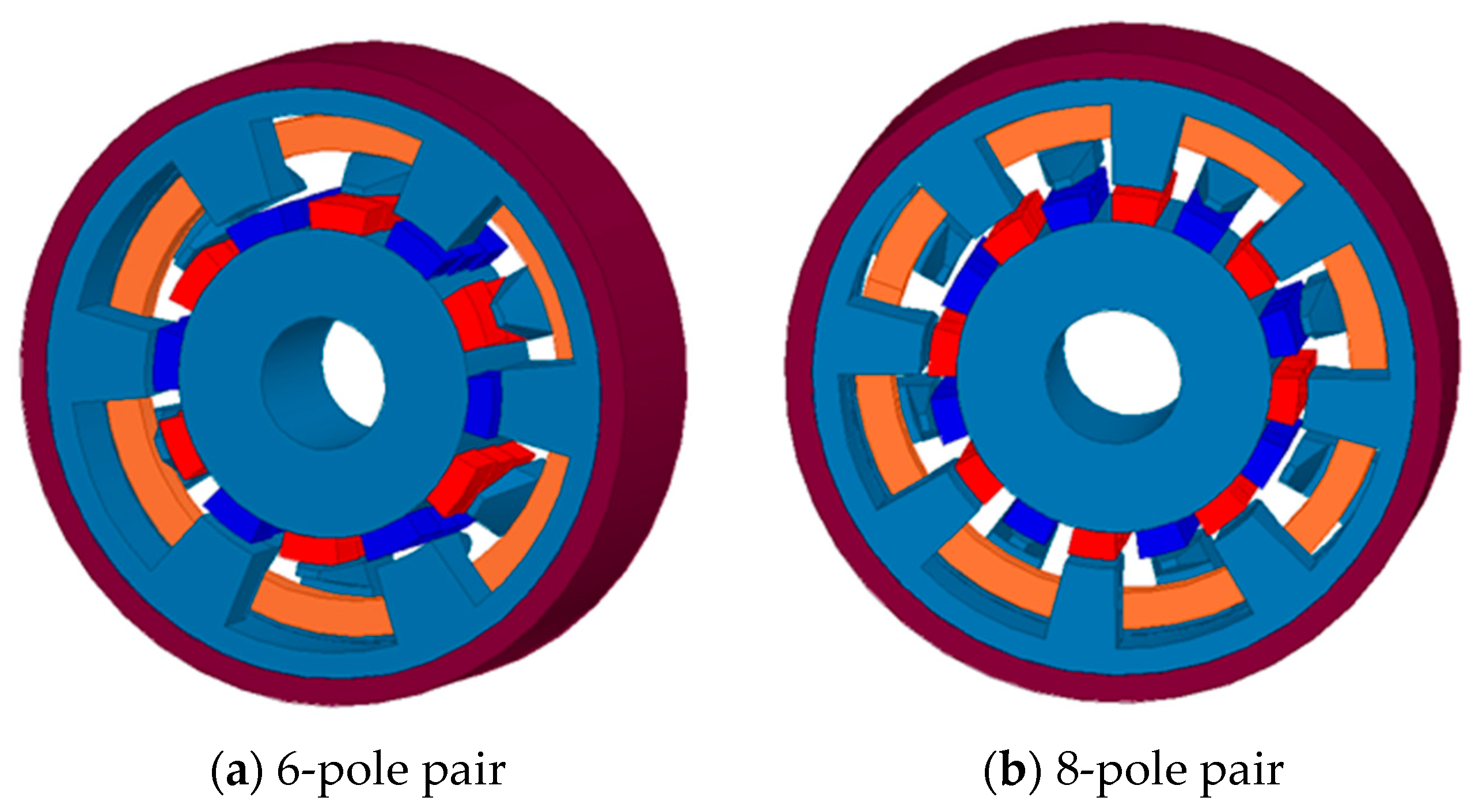
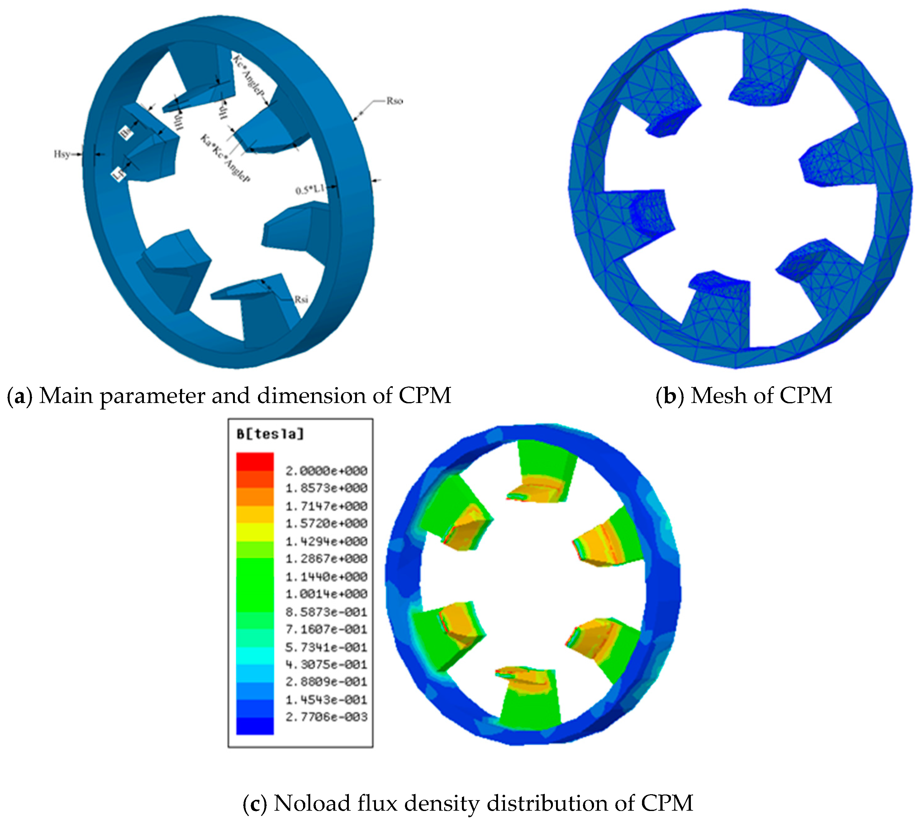
As mentioned above the number of pole pairs plays an important in affecting the performance of the machine. Thus, it needs to first be optimized. Figure 2 shows the CPM with different numbers of pole pairs and unequal stator claw pole teeth structure. In this paper, pole pair numbers of 6, 8, 10, and 12 were selected for analysis and comparison. The main parameter of the unequal stator claw pole structure is illustrated in Figure 3a. As shown, the Rso equaled 33.5 mm, Rsi equaled 18.5 mm, L1 equaled 18.2 mm, AngleP equaled 30° mechanically, Kc equaled 0.825, Ka equaled 0.45, Hp equaled 3mm, and Bs equaled 4 mm. As the very complex structure and nonlinear soft magnetic permeability of SMC materials were adopted for the CPM, 3D FEM, specifically the magnetostatic module of MAXWELL 3D, was used for the analysis, as for the boundary setting, there was no symmetrical boundary needed, thus the default boundary was adopted. Figure 3b shows the mesh of CPM, and Figure 3c shows the no-load flux density distribution of the stator of the CPM.
3. Torque Equation Deduction
The electromagnetic power of the CPM can be expressed as:
where m is the number of phases, T the electrical period, Em the magnitude of phase back EMF, and Im the magnitude of phase current. The back EMF can be computed by:
where Ncoil is the number of turns per phase, and φ the flux per turn, which can be expressed as:
The electrical angular speed has the form of:
where Pr is the number of rotor pole pairs, and ωr is the mechanical angular speed. The phase current can be expressed as:
where Ac is the cross-sectional area of the coil, and Jm the current density (magnitude value). The number of turns per phase can be computed by:
where Ns is the number of slots, Ksf is the slot fill factor, and As is the slot area. By combining the above equations and ignoring the stator resistance loss, the output power can be expressed as:
where η is the efficiency. The output torque can be calculated by:
To simplify the analysis, the torque capability can be expressed by the electromagnetic torque:
The flux linkage per coil for the CPM is:
where Bg is the air gap flux density, Rsi the inner radius of the stator, kc the claw pole arc ratio, Bs is the thickness of stator wall, f(kaLp, kphp) is the effect of the claw pole dimension to flux per coil, ka is the ratio of the short edge width to the long edge width of the claw pole teeth, Lp is the length of the claw pole teeth, kp is the ratio of the short edge thickness to the long edge thickness, and hp is the thickness of the near-edge claw pole teeth. The coil window area of CPM is:
where L1 is the effective axial length of one disk, Rso is the outer radius of stator, and hsy is the length of stator yoke. The torque for CPM can then be obtained by:
It can be seen that if the above equation meets:
then the electromagnetic torque can reach maximum.
By defining the ratio of the axial length to the outer radius of the motor (λ), for a given volume (V) and λ, the outer radius of the machine can be expressed as:
Thus, it can be found that the torque per unit volume has the following relationship with respect to λ and V:
It can be concluded that increasing the ratio of the axial length to the outer radius can increase the torque density of the CPM. Depending on the power function, the following parameters can affect the torque ability of CPM as well: the ratio of the claw pole short edge to the long edge, and the ratio of the claw pole to the pole pitch. Moreover, the torque ability of CPM is related to the number of pole pairs. In the following sections, for the claw pole structure of the CPM, the main dimensions of the CPM and other important factors are studied.
4. Claw Pole Structure Design
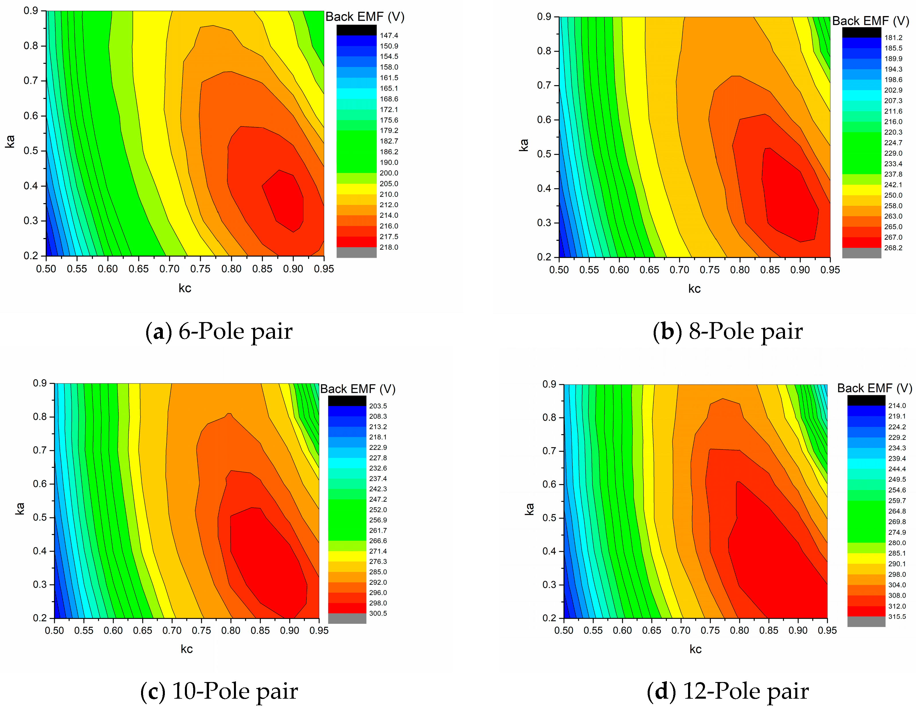
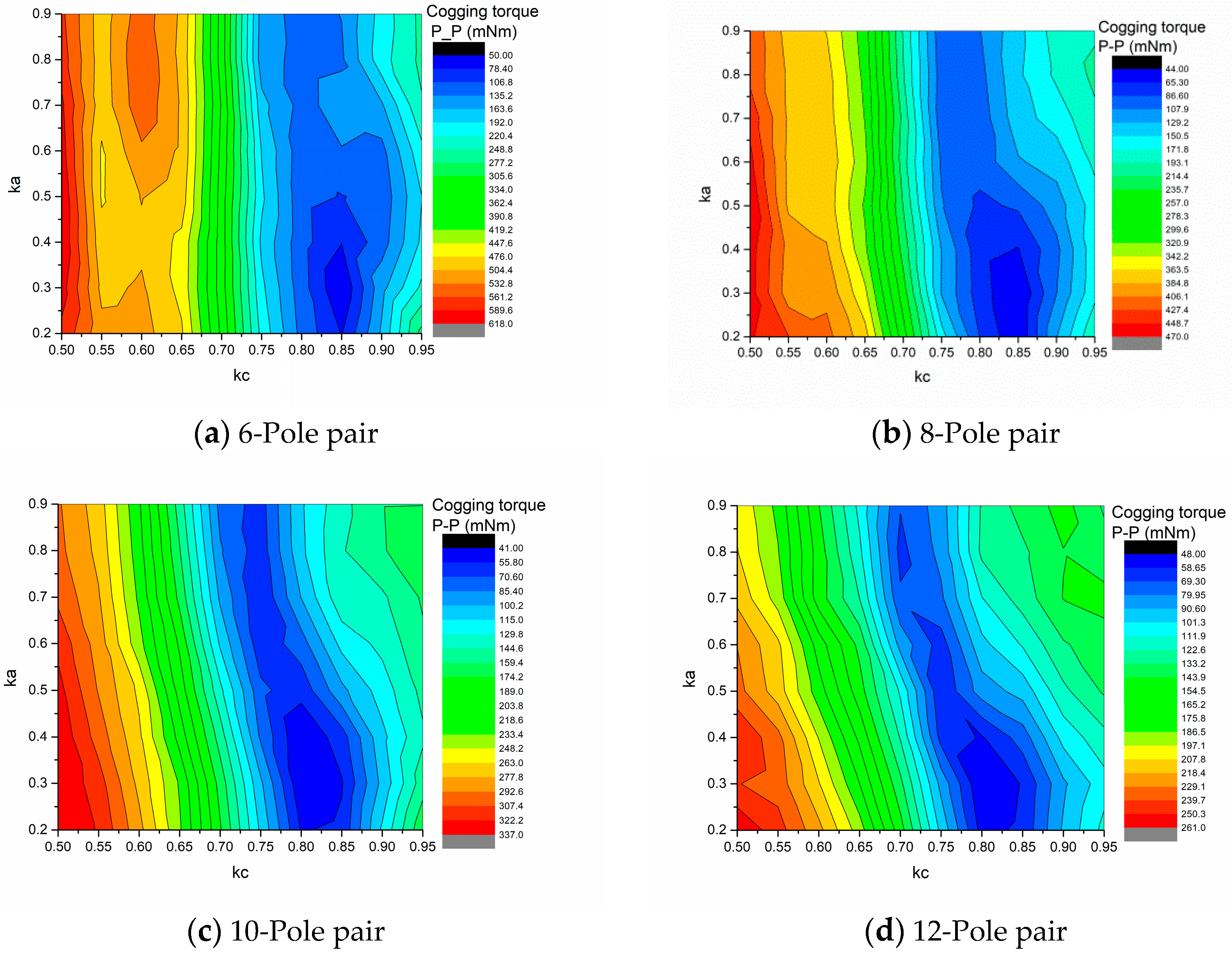
As investigated in [3], the unequal stator claw pole teeth can affect the air gap magnetic field distribution, and thus the cogging torque and torque ripple of CPM can be reduced, and the average torque can be improved with an optimal claw pole teeth design. For the different numbers of pole pairs of the CPM, whether there is a general rule for the parameter design is a very important issue for the design of CPM, since if the general design rules can be found, then it can provide the machine designer with a key design guideline to design this kind of machine. By using the 3D FEM, the back electromotive force (EMF), cogging torque, and rated torque of CPM with the variation of the ratio of the claw pole teeth to the pole pitch are simplified as kc, and the ratio of the stator claw pole short edge to the stator claw pole long edge are simplified as ka, as illustrated in Figure 4, Figure 5 and Figure 6 respectively. It can be found that though the number of pole pairs was changed from 6 to 12, the main relationship of the back EMF, cogging torque, and the rated torque of CPM with the variation of kc and ka was kept the same. As shown in Figure 4, the maximum back EMF of the CPM could be achieved when kc was lower than 0.5, and when ka was between 0.8 and 0.95. As shown in Figure 5, the cogging torque of CPM was low when kc was lower than 0.5 and ka was between 0.8 and 0.85. As shown in Figure 6, the average torque of CPM could achieve a maximum value when the kc was higher than 0.8. Therefore, kc equals 0.825 and ka equals 0.45 were selected to be the best parameters for the CPM.
5. Split Ratio and Thickness of the Stator Wall Design
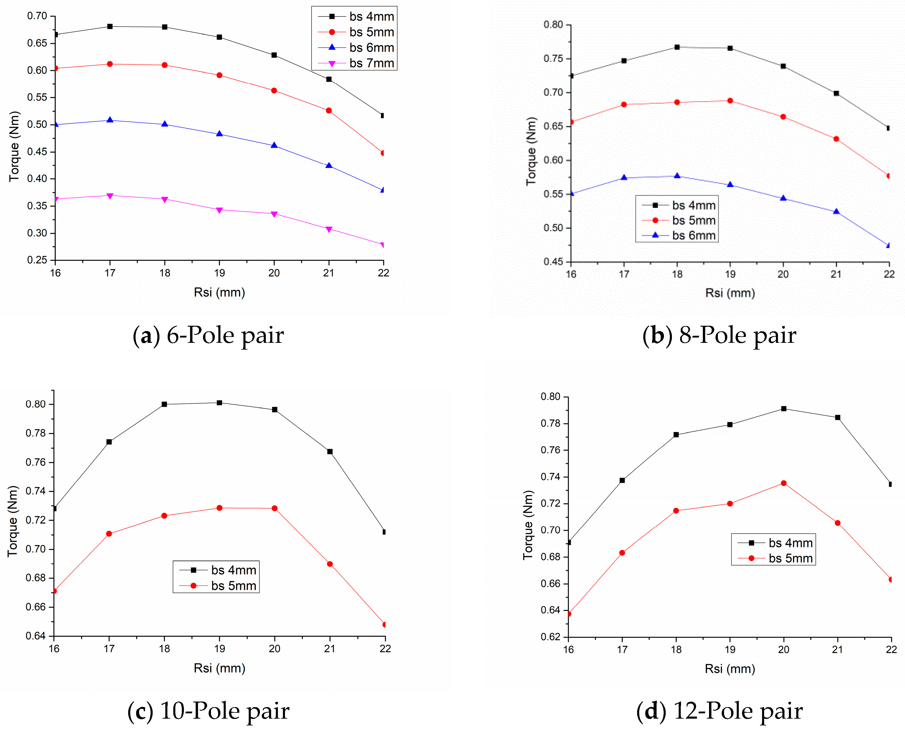
For the electrical machine design, the split ratio is a crucial parameter, since it determines the balance of the magnetic load and the electric load. The thickness of the stator wall is another important parameter to determine the balance of magnetic load and electric load. The torque of the CPM with the variation of stator wall thickness and the stator inner radius is illustrated in Figure 7. To make sure that the stator wall can have enough mechanical strength, the minimum stator wall thickness is designed to not be to lower than 4 mm. As shown, the maximum torque of these CPMs was achieved when the stator wall thickness equaled 4 mm, and the maximum stator inner radius of CPM was around about 18 mm. The CPMs with numbers of pole pairs of 6, 8, and 10 could achieve the maximum torque, and the CPM with a number of pole pairs of 12 could achieve the maximum torque when its stator inner radius equaled 20 mm. Figure 8 shows the overall performance comparison of the CPMs with different pole pair numbers and the best stator wall thickness. As shown, the torque of the CPM with a pole pair number of 10 could achieve the maximum value with a stator inner radius of 18 mm. The efficiency of CPM was increased as the stator inner radius increased; the main reason for this was that a higher stator inner radius resulted in a lower space for the copper, and thus there was lower copper loss. Compared with the other number of pole pairs, the pole pair number of 10 showed the highest efficiency. The power factor is another critical parameter; the lower the power factor, the higher the required power capacity of the driving power electronics. When the number of pole pairs increased, the flux leakage increased, and thus the power factor decreased. For the stator inner radius, the power factor increased with an increase in the stator inner radius.
6. Magnet Skewing Design
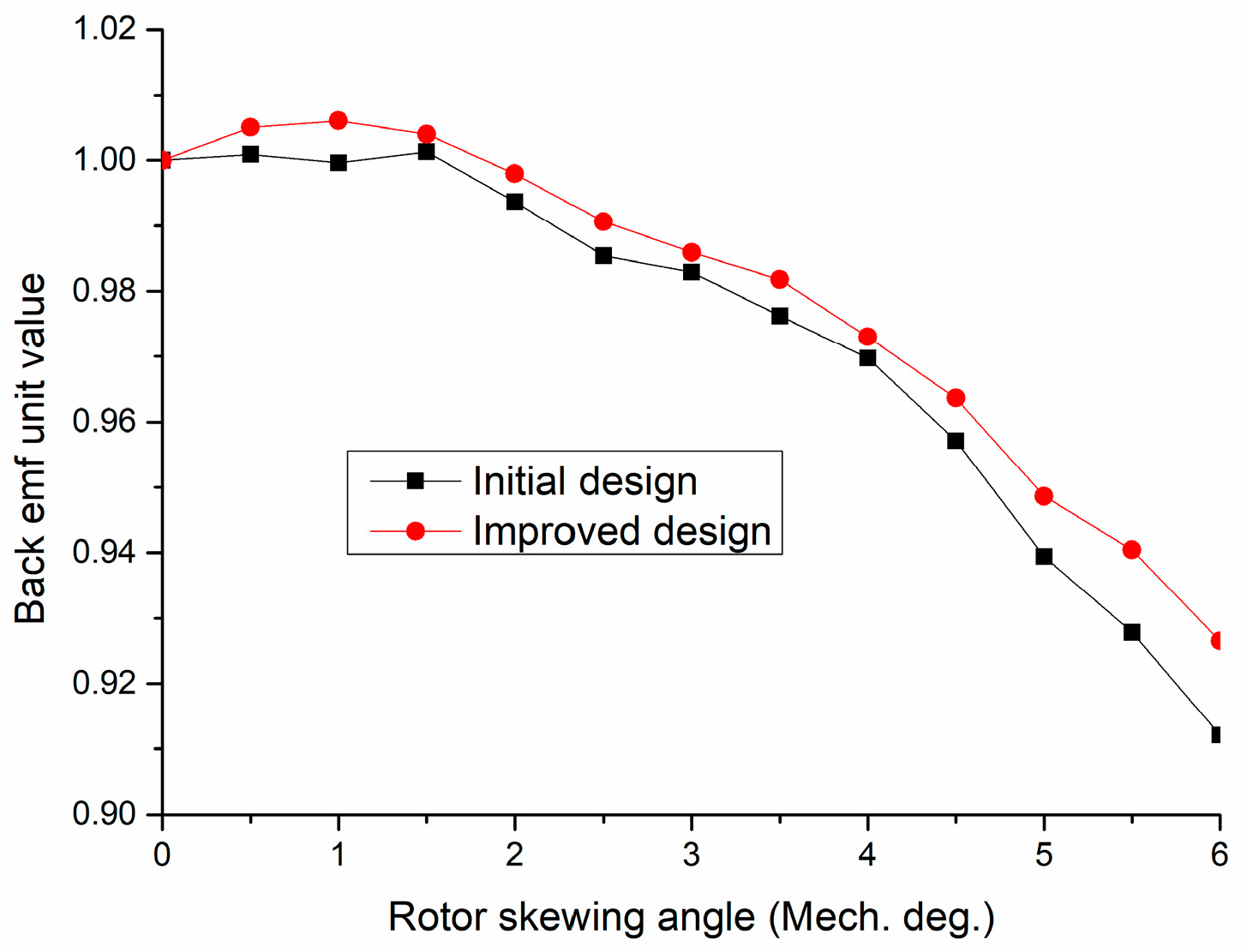
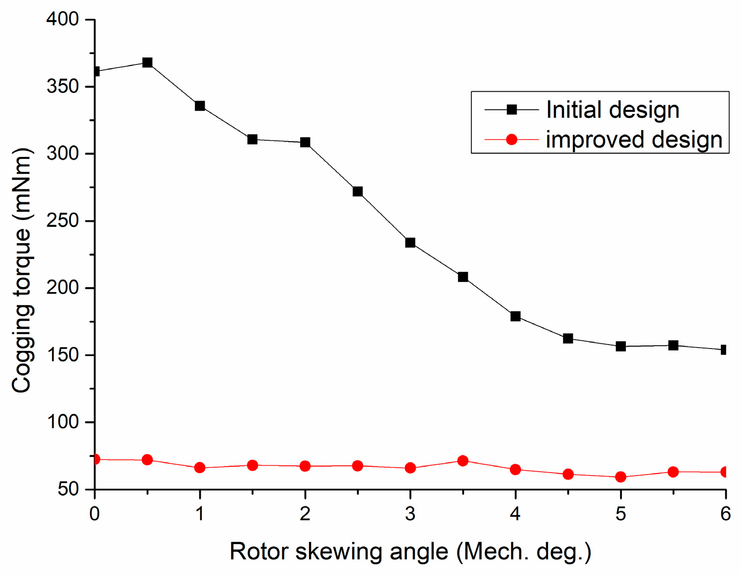
Magnet skewing is an effective way to reduce the cogging torque of CPM. The magnet skewing rotor and its definition of skewing angle are illustrated in Figure 9. In [5], various kinds of methods were adopted for the cogging torque reduction of this kind of machine, and an accurate skewing angle is obtained. In addition, the unequal claw pole tooth is another way to reduce the cogging torque of CPM. In this paper, the improved design meant that the machine had been optimized for achieving the best performance, including low cogging torque and high output torque, by using the above methods. The unequal stator claw pole teeth structure design and the initial design meant that the machine is had an equal stator claw pole teeth design, as shown in Figure 1. Thus, for a fair comparison of the back EMF, a per-unit value is used. Figure 10 shows the back EMF of the CPM with the different magnet skewing angles; the initial design of the CPM referred to a CPM with a kc of 0.667 and a ka of 1; the improved design referred to a CPM after optimization of stator wall thickness, stator inner radius, kc, and ka. As shown, the back EMF was reduced with an increase in the rotor skewing angle. Figure 11 shows the peak-to-peak cogging torque of these two CPMs. As shown, with an increse of the skewing angle, the cogging torque of CPM reduced greatly. For the improved design, as the cogging torque was decreased greatly with the optimization of kc and ka, the cogging torque remained the same with the increase of the rotor skewing angle. Therefore, with the improved claw pole teeth design, there was no need to use the magnet skewing method to reduce the cogging torque and torque ripple for the CPM.
7. Consequent Pole Design
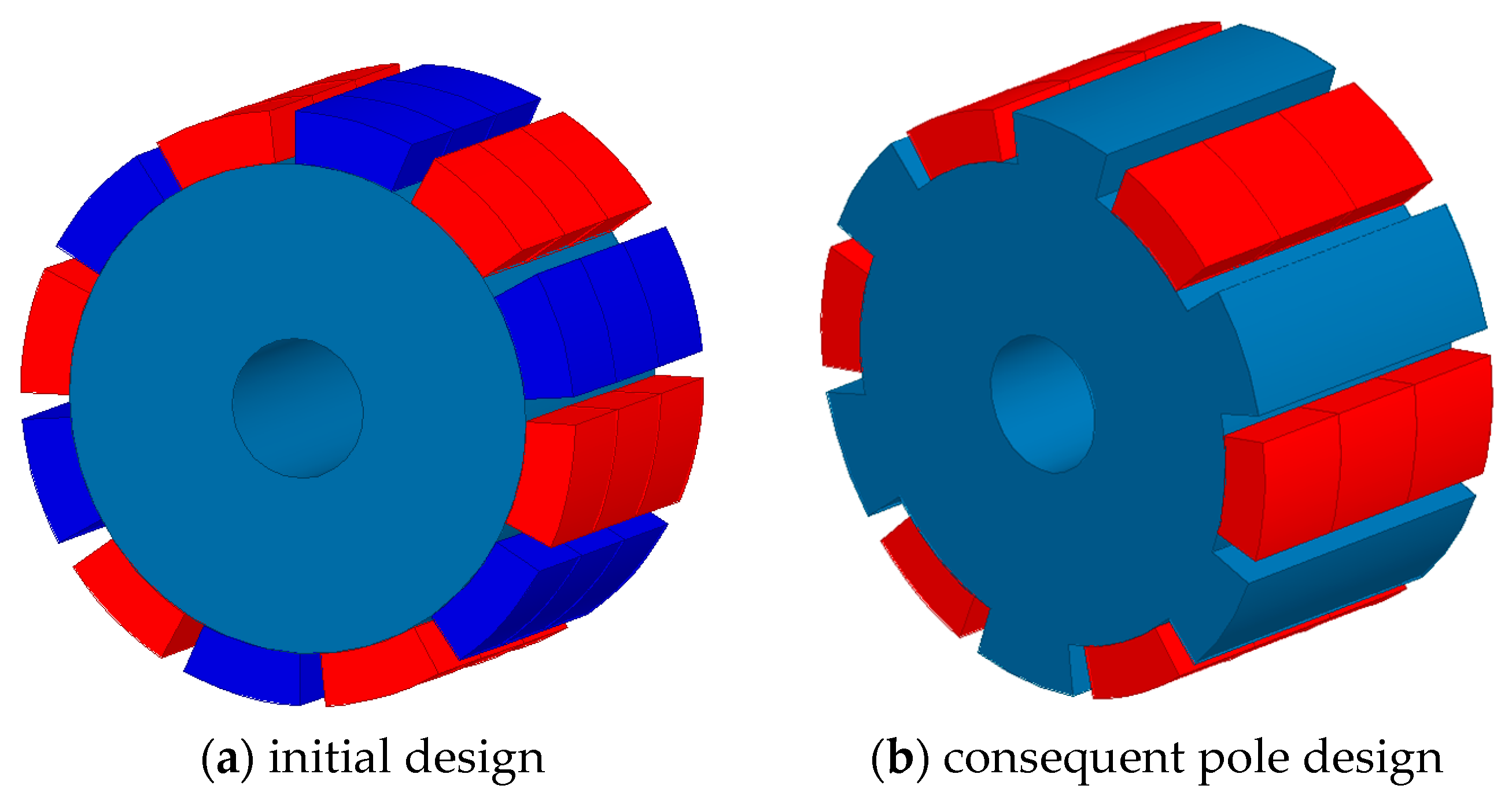
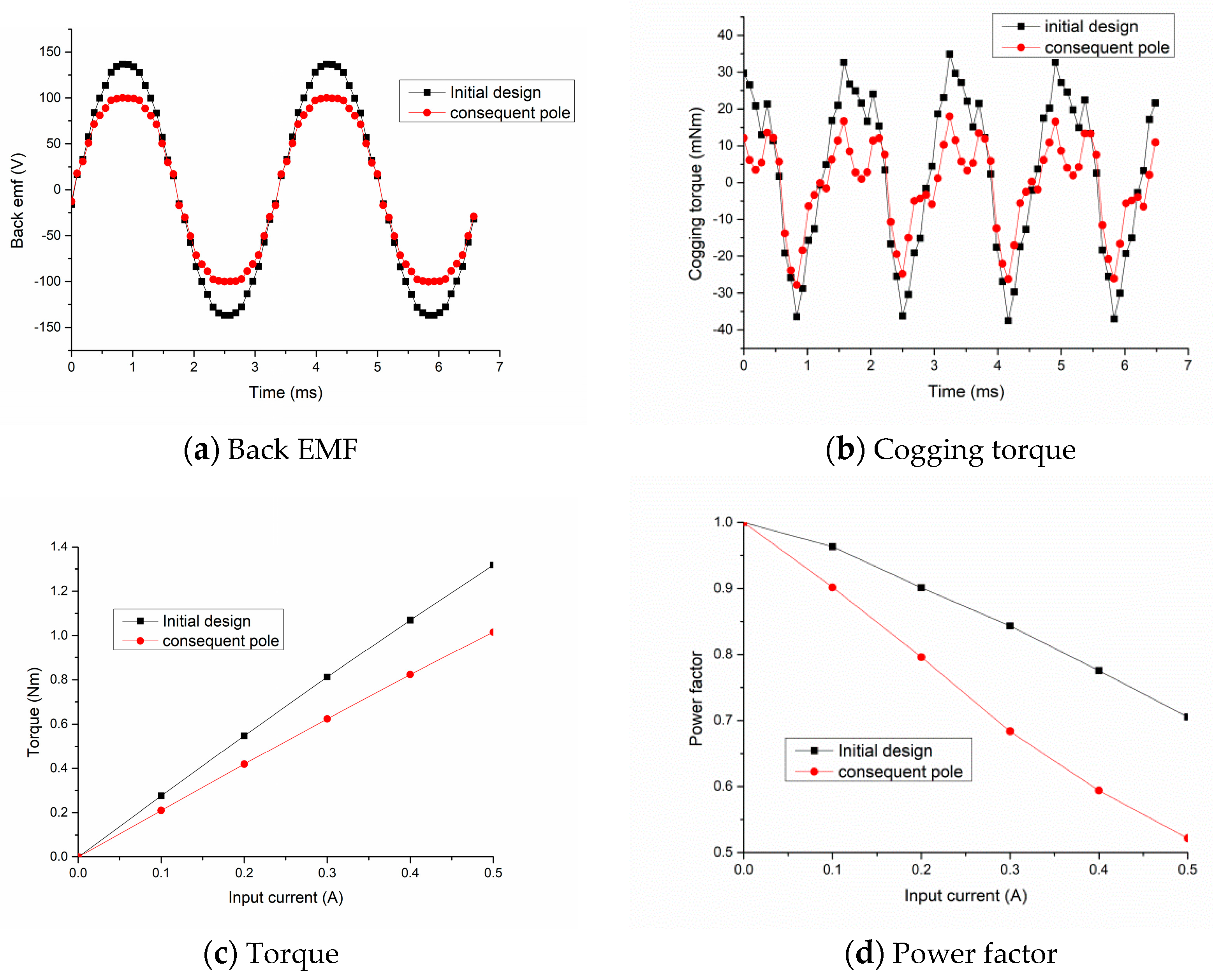
Currently, the price for rare earth magnets is very high. Thus, there is a trend to use fewer magnets, or to use non-rare earth magnets in the PM machine. The consequent pole magnet is an effective way to reduce the magnet volume in the PM machine, and both the consequent pole rotor and the initial rotor for the CPM are illustrated in Figure 12. Though a half volume of the magnet was used in the consequent pole CPM, the performance of CPM was not reduced too much, as shown in Figure 13. As shown, the magnitude of CPM with the consequent pole magnet was about 100 V, while that for the normal CPM was about 140 V. As for the cogging torque comparison, the peak-to-peak cogging torque of the CPM with the consequent pole magnet rotor design was about 50 mNm and that for the normal CPM was about 65 mNm. Figure 11 shows the torque comparison of both. As shown, the torque of the normal CPM was higher at the rated current of 0.25 A, the torque for the normal CPM was about 0.6 Nm, and that for consequent pole CPM was about 0.5 Nm. A power factor comparison showed that the normal CPM could have a higher power factor, which resulted from the high PM flux linkage of the normal CPM and the consequent magnet pole CPM with higher leakage inductance. As shown with an input current of 0.5 A, the power factor for the consequent magnet pole was about 0.52, and that for normal CPM was about 0.72. Therefore, though the magnet used in the consequent pole magnet CPM was the half as that of normal CPM and the total cost of this machine was much lower, then the performance was not reduced too much. It can be concluded that for a high-performance application, the normal magnet configuration was a good choice, while for the application where the cost needed to be considered, the consequent pole magnet rotor configuration was a good candidate.
8. Gap Length Analysis
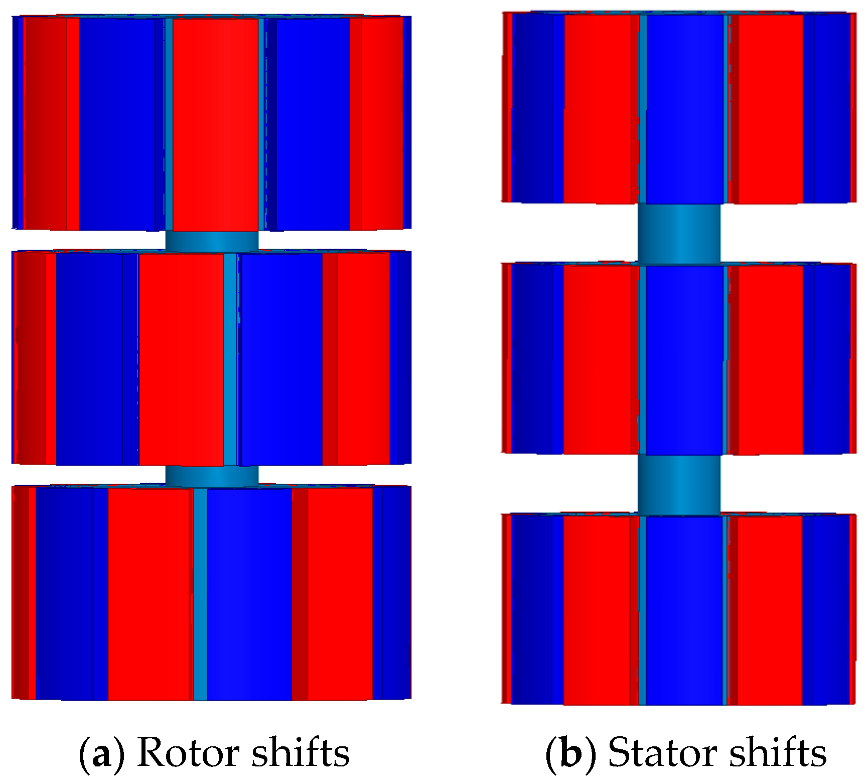
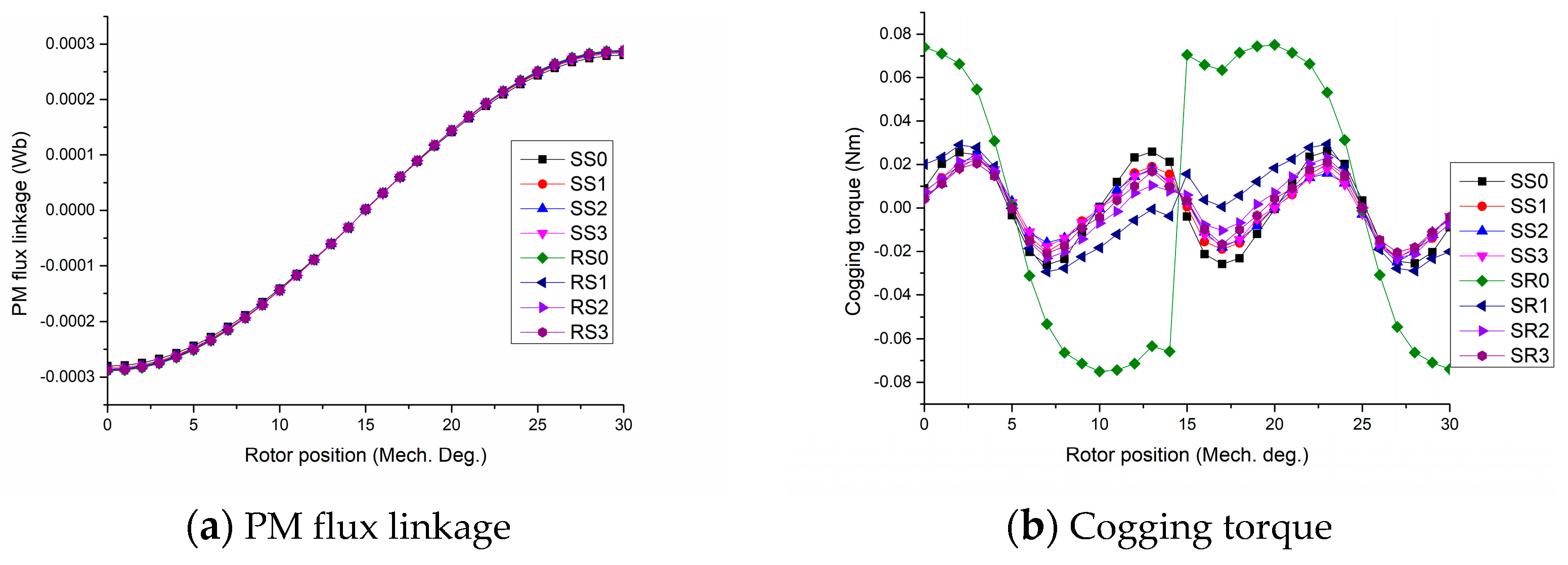
To form the symmetrical three-phase operation, the CPM needs to shift its adjacent stator module or rotor module over determined mechanical degree, and the adjacent phase needs to be a determined distance apart, to reduce its magnetic coupling effect. In the design of CPM, the torque density is a very important parameter to represent machine performance. Thus, the shortest distance between the adjacent phases which do not bring a great effect to the three-phase machine needs to be known. Both the shifts on the stator side or rotor side can give CPM three-phase operation, and the difference between these two methods has also been investigated in this section, as shown in Figure 14. Figure 15 shows the overall performance comparison of CPM with different axial gap lengths in the stator shift model or in the rotor shifts model. As shown, when the axial gap length increased, it did not result in a big difference for the PM flux linkage. Thus, the output torque did not depend on the length between the adjacent machine modules. For the inductance, it was found that both self-inductance and mutual inductance were decreased as axial gap length increased, while the difference between the shift methods was not notable. Compared with the stator shifts, the rotor shifts gave the CPM higher cogging torque. Thus, in the assembly of the three-phase CPM, the stator shifts were ideal. In addition, it was found that the effect resulting from the axial gap length is reduced when the axial gap length increased. In this CPM it was seen that the axial gap length of 2 mm was an ideal parameter.
9. Material Selection
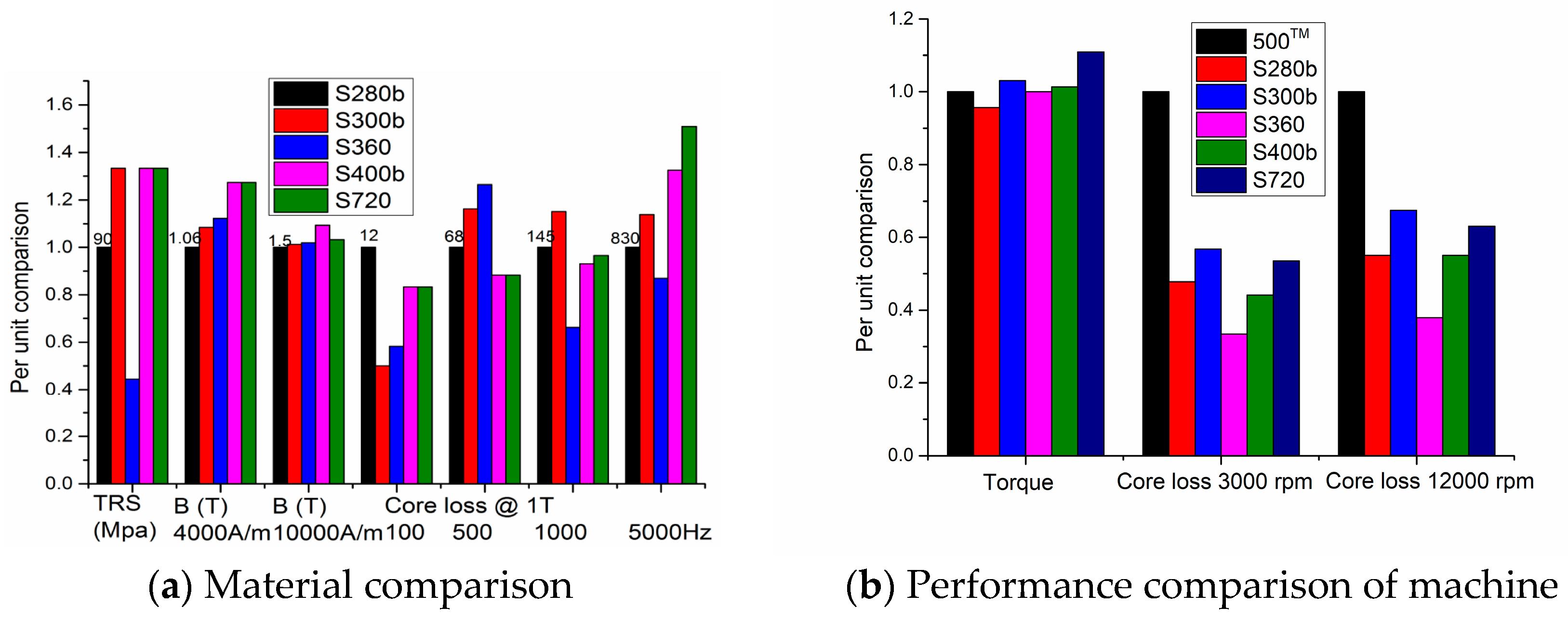
Due to its special properties, the material for the SMC has drawn great interest in past decades. Currently, the performance of SMC material has been improved greatly, including its mechanical properties, permeability, and core loss. Figure 16 shows five different SMC materials; S280b, S300b, and S400b had good mechanical properties which can be used for the machining process, and even after machining, their electromagnetic performance still kept well. With number increases, the permeability of the SMC material increases, and the core loss increases as well. For the CPM developed in this paper, its rated speed was about 3000 rpm, and the maximum speed was about 12,000 rpm. By using 3D FEM, the performances of CPMs with different SMC material were obtained, as shown in Figure 16b. The term 500TM refers to the old version of the SMOLAY material, and its performance is used as unit 1 for comparison. As shown, with a high permeability of SMC materials adopted, the torque ability of CPM could be improved. However, it was increased by lower than 1.1 times the CPM with 500TM. Based on the core loss comparison, it was seen that the core loss of the CPM was reduced greatly with the new SMC material adopted. The S280b, S300b, and S400b were good for the machining process, and their magnetic properties were reduced compared with S360 and S720. As for the comparison between S360 and S720, it was found that though the torque ability of the CPM was higher, the core loss of the CPM with S360 was much lower. Therefore, for mass production, S360 was a good candidate material. As well, for the comparison between S280b, S300b, and S400b, the conclusion was similar. The high torque ability resulting from the high permeability material resulted in the CPM having higher core loss due to the high core loss properties along with high permeability.
10. Analysis Method Verification
The calculations of the initial CPM were verified by the experimental results. The measured peak back EMF per turn of the initial CPM was about 0.091 V at 39.7 Hz. The back EMF per turn at 300 Hz was about 0.687 V, which was very close to the calculated result of 0.657 V. As well, the measured inductance per turn of the CPM was about 0.5 μH, which was quite equal to the calculated result of 0.49 μH. Therefore, the calculation method was correct in this paper, and a prototype for the new developed CPM is ongoing.
11. Conclusions
CPMs with SMC cores can be used for many high torque density drive applications. With the performance improvement of SMC material, some commercial CPM with SMC cores have appeared on the market. For the better utilization of CPM with SMC cores, its key design issues were discussed in this paper. Firstly, through a study of the unequal stator claw pole teeth structure, it can be seen that when the ratio of stator claw pole to its pole pitch equals 0.825 and the ratio of stator claw pole short edge to stator claw pole long edge equals 0.45, the torque of the CPM can achieve its highest output and with the lowest cogging torque and ripple, even though the number of its pole pairs changed from six to 12. Secondly, when the unequal stator claw pole teeth are used for the performance improvement, the magnet skewing will not play a good role in the cogging reduction. Thirdly, for the stator wall design, it can be seen that the torque ability is better when the stator wall thickness is lower . In this CPM, nearly all of the inner rotor CPMs can achieve a high torque output when the inner stator radius equals 18 mm. When the stator inner radius increases, its power factor will be increased. Fourthly, the consequent pole was a good way to improve the ratio of torque-to-cost, while the consequent pole can also result in a machine with a lower power factor. Fifthly, in the design of CPM with SMC cores, various kinds of materials can be selected, and it can be seen that the low-core loss material is the best selection for the developed CPM in this paper, since the PM machine is not sensitive to the permeability of the material used. Lastly, it can be found that with an increase in the number of pole pairs, the best design for the output torque will be achieved, while the power factor will be decreased as the flux leakage increases.
Author Contributions
All authors contributed to this work through collaboration. C.L. is the main author of this manuscript; J.L. and G.L. assisted to establish the finite element model and to perform the simulations; Y.W., J.Z. and Y.G. provided some useful suggestions in the construction of paper. All authors revised and approved the publication.
Acknowledgments
Hebei Province Education Department Youth Talent Leading Project under BJ2018037.
Conflicts of Interest
The authors declare no conflict of interest.
References
- Sun, X.D.; Shen, Y.C.; Wang, S.H.; Lei, G.; Yang, Z.B.; Han, S.Y. Core loss analysis of a novel 16/10 segmented rotor switched reluctance BSG motor for HEVs using nonlinear lumped parameter equivalent circuit model. IEEE/ASME Trans. Mechatron. 2018, 23, 747–757. [Google Scholar] [CrossRef]
- Guo, Y.; Zhu, J.; Dorrell, D.G. Design and analysis of a claw pole permanent magnet motor with molded soft magnetic composite core. IEEE Trans. Magn. 2009, 45, 4582–4585. [Google Scholar]
- Liu, C.C.; Lei, G.; Wang, T.S.; Guo, Y.G.; Wang, Y.H.; Zhu, J.G. Comparative study of small electrical machines with soft magnetic composite cores. IEEE Trans. Ind. Electron. 2017, 64, 1049–1060. [Google Scholar] [CrossRef]
- Hasan, I.; Husain, T.; Uddin, M.W.; Sozer, Y.; Husain, I.; Muljadi, E. Analytical modeling of a novel transverse flux machine for direct drive wind turbine applications. In Proceedings of the IEEE Energy Conversion Congress and Exposition (ECCE), Montreal, QC, Canada, 20–24 September 2015. [Google Scholar]
- Liu, C.C.; Lu, J.W.; Wang, Y.H.; Lei, G.; Zhu, J.G.; Guo, Y.G. Techniques for reduction of the cogging torque in claw pole machines with SMC cores. Energies 2017, 10, 1541. [Google Scholar] [CrossRef]
- Lei, G.; Zhu, J.G.; Guo, Y.G. Multidisciplinary Design Optimisation Methods for Electrical Machines and Drive Systems; Springer: Berlin/Heidelberg, Germany, 2016. [Google Scholar]
- Weh, H.; May, H. Achievable force densities for permanent magnet excited machines in new configurations. In Proceedings of the International Conference on Electrical Machines, Munich, Germany, 8–10 September 1986. [Google Scholar]
- Lu, K.; Wu, W. High torque density transverse flux machine without the need to use SMC material for 3-D flux paths. IEEE Trans. Magn. 2015, 51. [Google Scholar] [CrossRef]
- Ahmed, A.; Husain, I. Power factor improvement of a transverse flux machine with high torque density. In Proceedings of the IEEE International Electric Machines & Drives Conference (IEMDC 2017), Miami, FL, USA, 21–24 May 2017; pp. 1–6. [Google Scholar]
- Washington, J.G.; Atkinson, G.J.; Baker, N.J.; Jack, A.G.; Mecrow, B.C.; Jensen, B.B.; Pennander, L.; Nord, G.L.; Sjöberg, L. Three-phase modulated pole machine topologies utilizing mutual flux paths. IEEE Trans. Energy Convers. 2012, 27, 507–515. [Google Scholar] [CrossRef] [Green Version]
- Zhu, J.G.; Guo, Y.G.; Lin, Z.W.; Li, Y.J.; Huang, Y.K. Development of PM transverse flux motors with soft magnetic composite cores. IEEE Trans. Magn. 2011, 47, 4376–4383. [Google Scholar] [CrossRef]
- Zhang, B.; Seidler, T.; Dierken, R.; Doppelbauer, M. Development of a yokeless and segmented armature axial flux machine. IEEE Trans. Ind. Electron. 2016, 63, 2062–2071. [Google Scholar] [CrossRef]
- Lei, G.; Zhu, J.; Guo, Y.; Liu, C.; Ma, B. A Review of design optimization methods for electrical machines. Energies 2017, 10, 1962. [Google Scholar] [CrossRef]
- Schoppa, A.; Delarbre, P. Soft magnetic powder composites and potential applications in modern electric machines and devices. IEEE Trans. Magn. 2014, 50. [Google Scholar] [CrossRef]
- Krings, A.; Boglietti, A.; Cavagnino, A.; Sprague, S. Soft magnetic material status and trends in electric machines. IEEE Trans. Ind. Electron. 2017, 64, 2405–2414. [Google Scholar] [CrossRef]
- Jan, D.; Steinborn, G.; Hofmann, W. Torque, power, losses, and heat calculation of a transverse flux reluctance machine with soft magnetic composite materials and disk-shaped rotor. IEEE Trans. Ind. Appl. 2015, 51, 1494–1504. [Google Scholar]
- Jiang, S.L.; Hu, J.H.; Wang, B.C.; Zhao, M.; Shang, J. Electromagnetic design of a novel hybrid flux SMCs PMSM. In Proceedings of the IEEE Transportation Electrification Conference and Expo Asia-Pacific (ITEC Asia-Pacific), Harbin, China, 2–5 August 2017; pp. 1–5. [Google Scholar]
- Kwon, Y.; Kim, W. Electromagnetic analysis and steady-state performance of double-sided flat linear motor using soft magnetic composite. IEEE Trans. Ind. Electron. 2017, 64, 2178–2187. [Google Scholar] [CrossRef]
- Lei, G.; Liu, C.C.; Zhu, J.G.; Guo, Y.G. Techniques for multilevel design optimization of permanent magnet motors. IEEE Trans. Energy Convers. 2015, 30, 1574–1584. [Google Scholar] [CrossRef]
Figure 1.
Topology of the initial claw pole machine, (a) stator, (b) rotor.
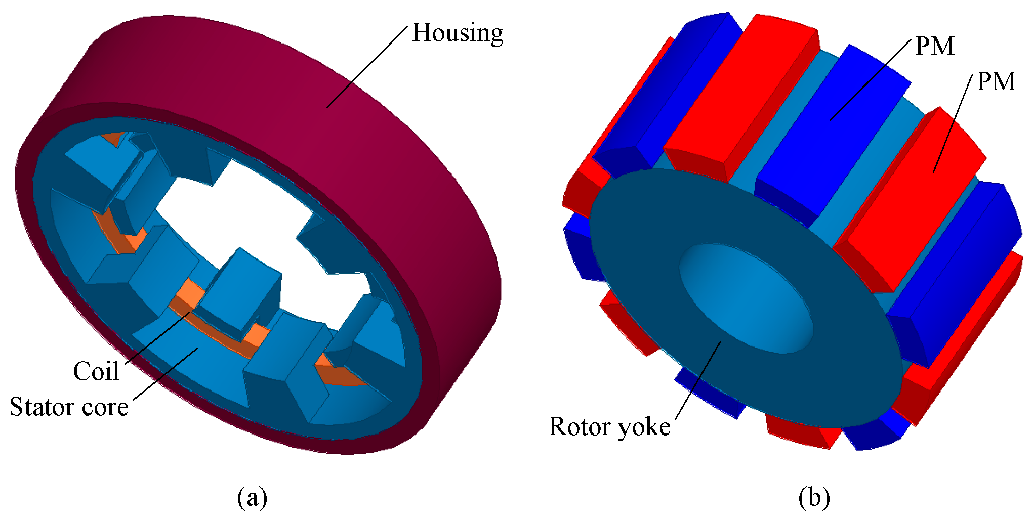
Figure 2.
Machine topology of a claw pole machine with different numbers of pole pairs.

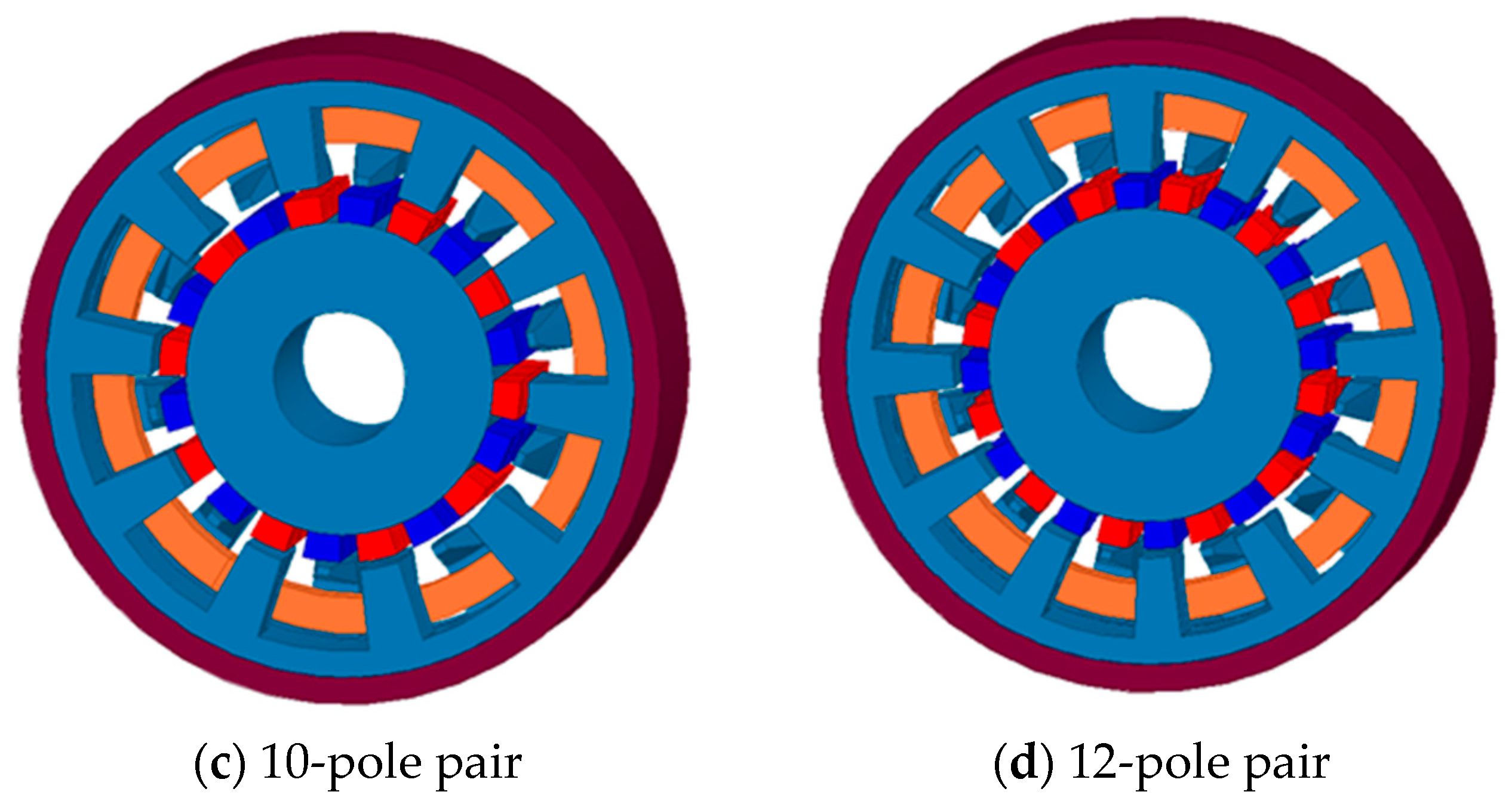
Figure 3.
Main parameter and dimension, mesh and no load flux density distribution of a claw pole machine (CPM).
Figure 3.
Main parameter and dimension, mesh and no load flux density distribution of a claw pole machine (CPM).

Figure 4.
Back EMF of CPM with the variation of the ratio of the pole pitch and the ratio of the claw pole short edge to long edge.
Figure 4.
Back EMF of CPM with the variation of the ratio of the pole pitch and the ratio of the claw pole short edge to long edge.

Figure 5.
Cogging torque of CPM with the variation of the ratio of the pole pitch and the ratio of the claw pole short edge to long edge.
Figure 5.
Cogging torque of CPM with the variation of the ratio of the pole pitch and the ratio of the claw pole short edge to long edge.

Figure 6.
Torque of CPM with the variation of the ratio of the pole pitch and the ratio of the claw pole short edge to long edge.
Figure 6.
Torque of CPM with the variation of the ratio of the pole pitch and the ratio of the claw pole short edge to long edge.
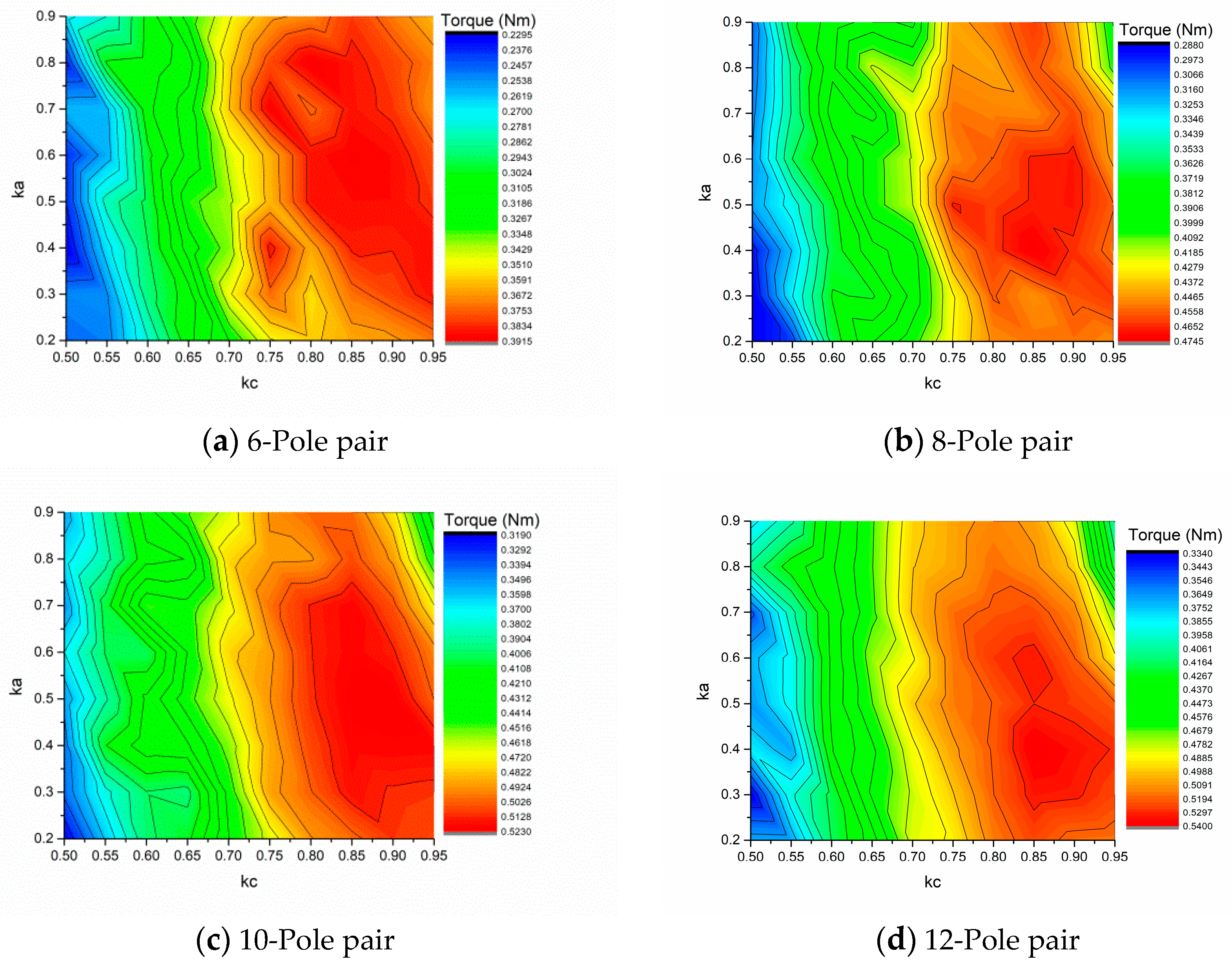
Figure 7.
Torque of CPM with variation of the stator inner radius and stator wall thickness.

Figure 8.
Overall performance comparison of the CPM with different numbers of pole pairs and different design parameters.
Figure 8.
Overall performance comparison of the CPM with different numbers of pole pairs and different design parameters.
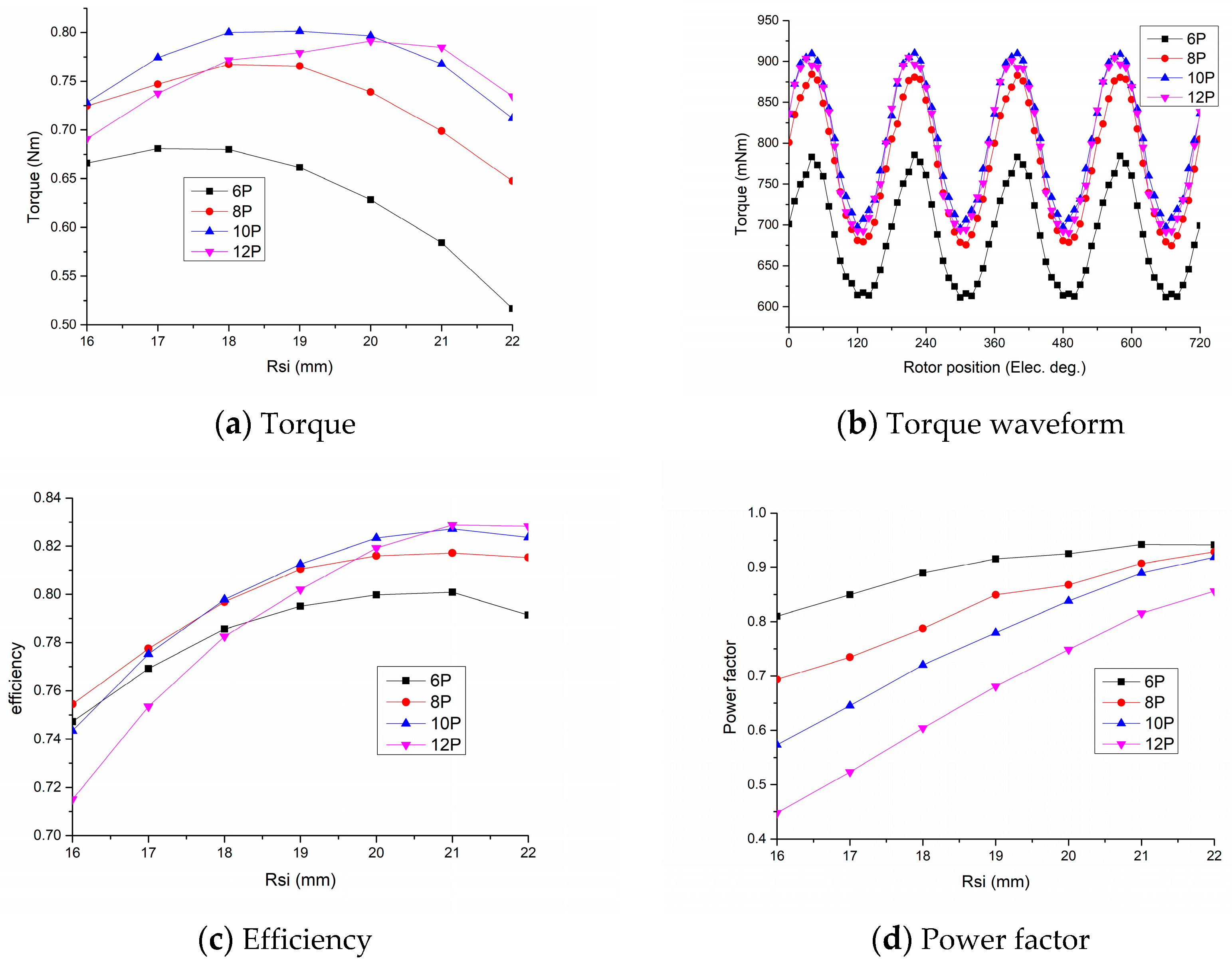
Figure 9.
Magnet skewing design of the CPM.
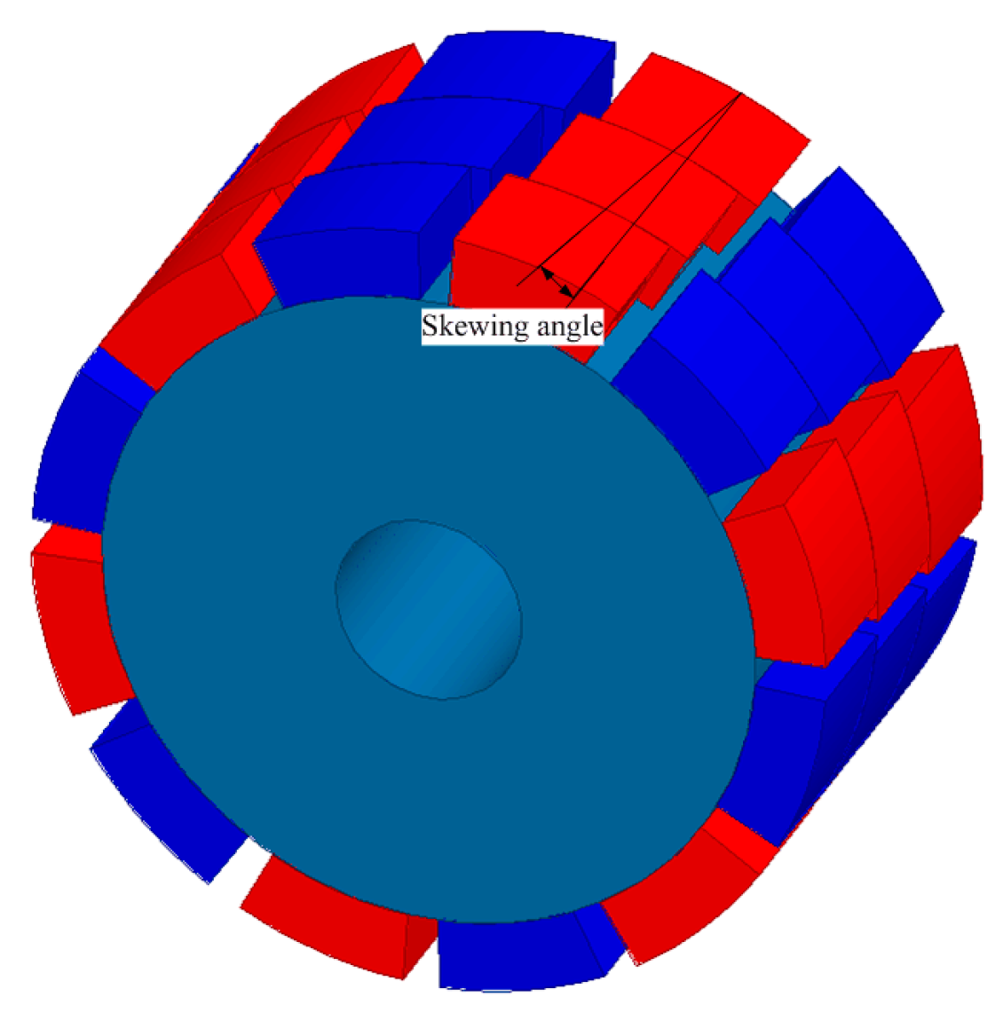
Figure 10.
Back EMF comparison of the CPM with the a different magnet skewing angle; initial design is with the equal claw pole teeth width design as shown in Figure 1, and improved design is with the optimized unequal stator claw pole structure.
Figure 10.
Back EMF comparison of the CPM with the a different magnet skewing angle; initial design is with the equal claw pole teeth width design as shown in Figure 1, and improved design is with the optimized unequal stator claw pole structure.

Figure 11.
Cogging torque comparison.

Figure 12.
Different magnet designs for CPM.

Figure 13.
Overall performance comparison of CPM with the initial design and the consequent pole magnet design.
Figure 13.
Overall performance comparison of CPM with the initial design and the consequent pole magnet design.

Figure 14.
Three-phase topology of CPM, (a) Rotor shifts, and (b) Stator shifts.

Figure 15.
Overall performance comparison of CPM with different axial gap length, stator shifts (SS), and rotor shifts (RS).
Figure 15.
Overall performance comparison of CPM with different axial gap length, stator shifts (SS), and rotor shifts (RS).

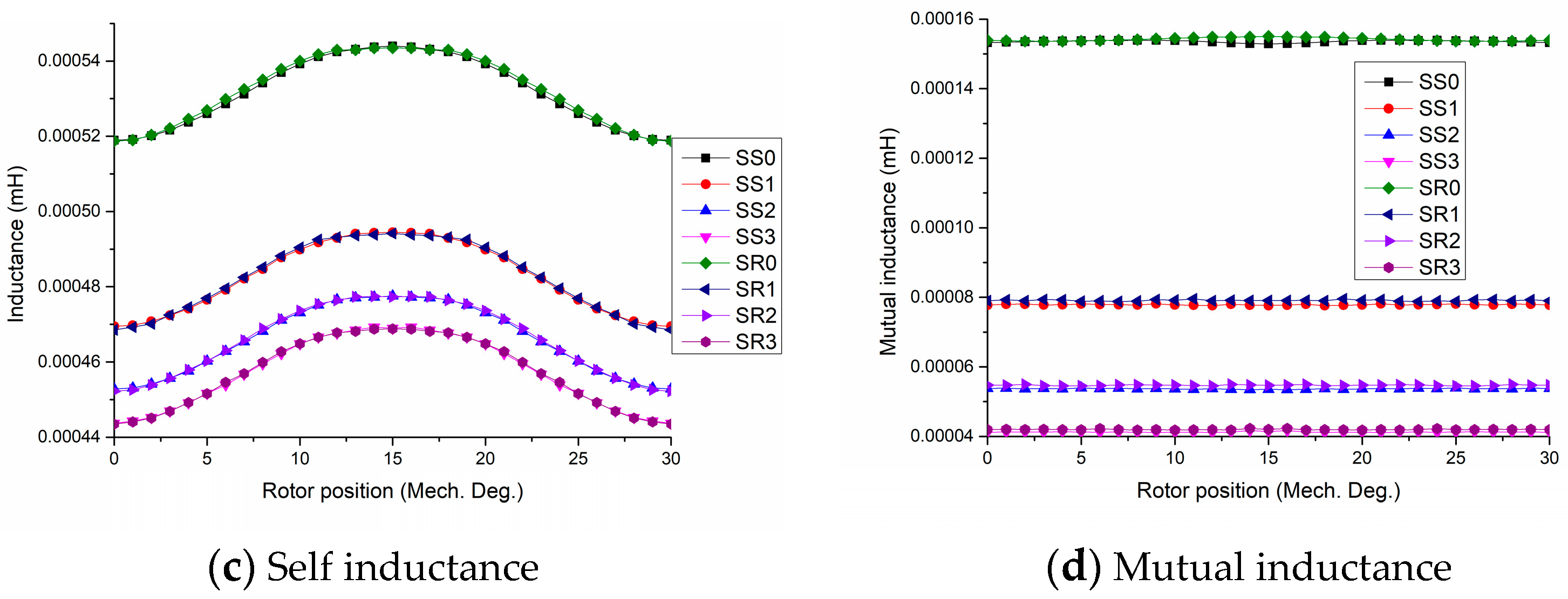
Figure 16.
Performance comparison between CPM with different SMC materials.


Table 1.
Dimension and key parameters.
| Dimension and Parameters | Quantities |
|---|---|
| Number of phases | 3 |
| Number of pole pairs | 6 |
| Stator outer radius (mm) | 33.5 |
| Rotor outer radius (mm) | 20.5 |
| Air gap length (mm) | 1 |
| Number of claw poles | 12 |
| Effective axial length (mm) | 54.56 |
| Pole arc of magnets and claw pole (mechanical degree) | 20 |
| Magnetization direction | Radial |
| Slot factor | 0.43 |
| Number of turns | 256 |
| PM materials | NdFeB, N30M |
| Stator materials | SOMALOY 500TM |
© 2018 by the authors. Licensee MDPI, Basel, Switzerland. This article is an open access article distributed under the terms and conditions of the Creative Commons Attribution (CC BY) license (http://creativecommons.org/licenses/by/4.0/).
Share and Cite
MDPI and ACS Style
Liu, C.; Lu, J.; Wang, Y.; Lei, G.; Zhu, J.; Guo, Y. Design Issues for Claw Pole Machines with Soft Magnetic Composite Cores. Energies 2018, 11, 1998. https://doi.org/10.3390/en11081998
AMA Style
Liu C, Lu J, Wang Y, Lei G, Zhu J, Guo Y. Design Issues for Claw Pole Machines with Soft Magnetic Composite Cores. Energies. 2018; 11(8):1998. https://doi.org/10.3390/en11081998
Chicago/Turabian StyleLiu, Chengcheng, Jiawei Lu, Youhua Wang, Gang Lei, Jianguo Zhu, and Youguang Guo. 2018. "Design Issues for Claw Pole Machines with Soft Magnetic Composite Cores" Energies 11, no. 8: 1998. https://doi.org/10.3390/en11081998
Note that from the first issue of 2016, this journal uses article numbers instead of page numbers. See further details here.