Multi-Load Mode Analysis for Electric Vehicle Wireless Supply System

College of Automation, Chongqing University, Chongqing 400044, China
*
Author to whom correspondence should be addressed.
Energies 2018, 11(8), 1925; https://doi.org/10.3390/en11081925
Submission received: 9 July 2018
/
Revised: 19 July 2018
/
Accepted: 20 July 2018
/
Published: 24 July 2018
Abstract
:When electric vehicles (EVs) run on the wireless power supply coils, the multi-load working mode will appear, showing that that more than one EV is collecting energy from one coil. Aiming at the stability problem of multi-load mode, this paper mainly analyzes how the number of loads influences the system stability and defines the boundary condition of the load quantity. Meanwhile, an L-shaped coil structure and the T-shaped magnetic core structure are proposed to solve the problem of coil breakdown for high-power supply situations. The proposed structures effectively reduce the supply coils’ self-inductance on the premise of guaranteeing the power transfer, and ensure the security of the multi-load system. At last, the validity of theoretical analysis is verified by simulations and experiments.
1. Introduction
Due to environmental pollution and energy shortage, electric vehicles (EVs) are getting more and more attention. With the popularization of EVs, the traditional contact charging mode has more security risks and interface limitations. In addition, there are still some technical limitations, such as the long charging time, the size and weight of the battery pack, the limited driving distance, and the cost of the battery pack. Wireless power transfer (WPT) technology realizes non-contact transmission of electrical energy through electromagnetic coupling [1,2,3]. An EV wireless supply system can provide real-time energy supply for EVs, so the EV can carry a small battery pack or even remove the battery pack [4,5]. The wireless supply system can overcome the limitations of the current generation of EV.
The advantage of the dynamic wireless supply technology makes the research and application of relevant technology very active. In [6], the design and demonstration of a 25 kW dynamic wireless power transfer system for EVs were presented. The work in [7] presented the experimental study and analysis of the Inductor-Capacitor-Inductor (LCL)–LCL compensation network-based WPT system for EV. In [8], a dynamic wireless supply system with a narrow track rail width and a large air gap for EV was proposed. The work in [9] proposed an optimization method to determine the structure of magnetic coils. In [10], the multi-objective function of battery life and peak output power was constructed, and the arrangement rules of wireless charging devices were studied. In [11], an optimization method was presented to analyze the powered tracks configuration and optimize the battery capacity of the electric bus wireless power supply system under closed and open environments.
In order to realize the wireless power supply for EVs, it is necessary to lay long power supply coils. When the EVs run on the supply coils, a phenomenon may appear in which there are more than one vehicle collecting the energy from one particular coil. That is the multi-load working mode. In this mode, there are multiple power transmission channels, which is different from the traditional one-to-one transmission mode. In addition, the change of the load number and the load value make the primary circuit impedance parameters change dynamically, which leads to the drift of system working frequency, thereby greatly reducing the transmission power and the efficiency. In view of the above problems, the work in [12] proposes the conditions of the maximum transmission efficiency and the maximum output power for the multi-load system. In [13], the stability conditions of the multi-load system are derived based on the resonant point. The work in [14] analyzes the effect of multiple loads on the resonant frequency and the system’s efficiency. In multi-load mode, the power capacity of the system increases, which makes the resonant current larger. When the self-inductance of the supply coils is too large, the voltage at both ends of the coils will be too high [15,16]. If this happens, the supply coils will be punctured easily by the high voltage, which can cause a safety accident.
The above research mostly focuses on the output power, the transmission efficiency, and the frequency stability of the multi-load system. However, there is no in-depth study on the influence of the number of the loads on the stability of the multi-load system and the security of the supply coils. Therefore, this paper firstly gives the equivalent circuit model of the multi-load system. Secondly, the boundary conditions of the load number are analyzed, and a power supply coil structure suitable for high-power is proposed. Finally, the correctness of the theoretical analysis is verified by the simulation and the experiment.
2. The Wireless Supply System for EV
2.1. The System Topology
The wireless power supply for EVs refers to the real-time non-contact power supply through the supply coils while the EV is running. The wireless supply system for EV studied in this paper adopts the series series (SS) compensation topology, as shown in Figure 1. On the primary side, the voltage source E is injected into a full-bridge inverter network consisting of four insulated gate bipolar transistors (IGBTs) after direct current (DC)/DC transformation. Then, the energy enters the series resonant network composed of the capacitor Cp and the inductor Lp after the power inverter, so as to activate the high-frequency magnetic field in the Lp. On the secondary side, the motor or the battery will be provided the energy after the rectifying, the filtering, and the DC/DC transformation.
2.2. The Model of the Multi-Load System
In this paper, SS compensation topology is used as the research object. In addition, the mutual inductance between the secondary coils is ignored because the distance between the vehicles places the secondary coils far away from each other [17]. The system equivalent model is shown in Figure 2, where Us is the high-frequency voltage source, Rp is the internal resistance of the supply coil, and ip is the resonant current. The secondary coils Li (i = 1, 2, …, n) and the compensated capacitor Ci compose the n resonant network. Ri, Reqi, and ii represent the internal resistance of the secondary coil, the equivalent load resistance and the high-frequency current of the secondary side. Mpi represents the mutual inductance between the Lp and the Li.
According to the equivalent circuit model and the Kirchhoff voltage law (KVL), the relationship between the parameters of the system can be obtained as follows:
where, and . w represents the operating frequency of the system.
Generally, the following relationship should be satisfied for the secondary compensated network [18]:
represents the natural resonance frequency of the secondary side.
3. The Stability Analysis of the Multi-Load System
When the system works near the resonant frequency, the operating frequency can be expressed as , where indicates the degree to which the operating frequency deviates from the resonant frequency. Assuming Rsi = Ri + Reqi, then the impedance of the ith secondary side can be expressed as
Since the WPT system generally operates at a high frequency [19], can be negligible when ε is small. Therefore, Equation (3) can be simplified as
where represents the quality factor of the secondary side.
In the WPT system, the coupling of the secondary side to the primary side directly reflects the reflected impedance. The reflected impedance directly acts on the primary resonant network, and the reflected impedance Zri can be expressed as
Then the total impedance Zt of the system is
In order to ensure the transmission efficiency and the stability of the system, the system often works at the resonant frequency point, and avoids the phenomenon of multiple resonant points [20]. To avoid multiple resonant frequencies, the equation of Im {Zt} = 0 should have one root. Therefore, the derivative of Im {Zt} should be greater than zero when . In this case, the phase frequency characteristic curve of Zt passes through the resonant frequency point only with a positive slope, ensuring that the equation has only one solution.
If the n secondary coils are considered to be exactly the same—that is, L1 = … = Ln = L—and the EVs are considered to be on the supply coils, then the mutual inductance between the supply coil and the secondary coils is equal (Mp1 = … = Mpn = M). In addition, the value of the hypothetic resistance Rc is
By simplifying Equation (7), the boundary condition of the load number can be derived:
where there is a critical point, with a positive and negative slope around the resonant frequency, when .
If the n secondary sides are considered to be identical, the quality factor is the same. Therefore, Equation (9) can be expressed as
It can be known from Equation (9) that the load number appears to be less than 1 when Rc is small enough, which causes the phenomenon of power blocking. To ensure that the multi-load system can operate normally, the boundary condition of the Rc is
If the secondary sides are considered to be identical, the boundary condition of the load value can be expressed as:
The above boundary conditions can be used as the theoretical reference for the design of the multi-load system.
4. The Magnetic Coupler
4.1. The Structure of the Supply Coil
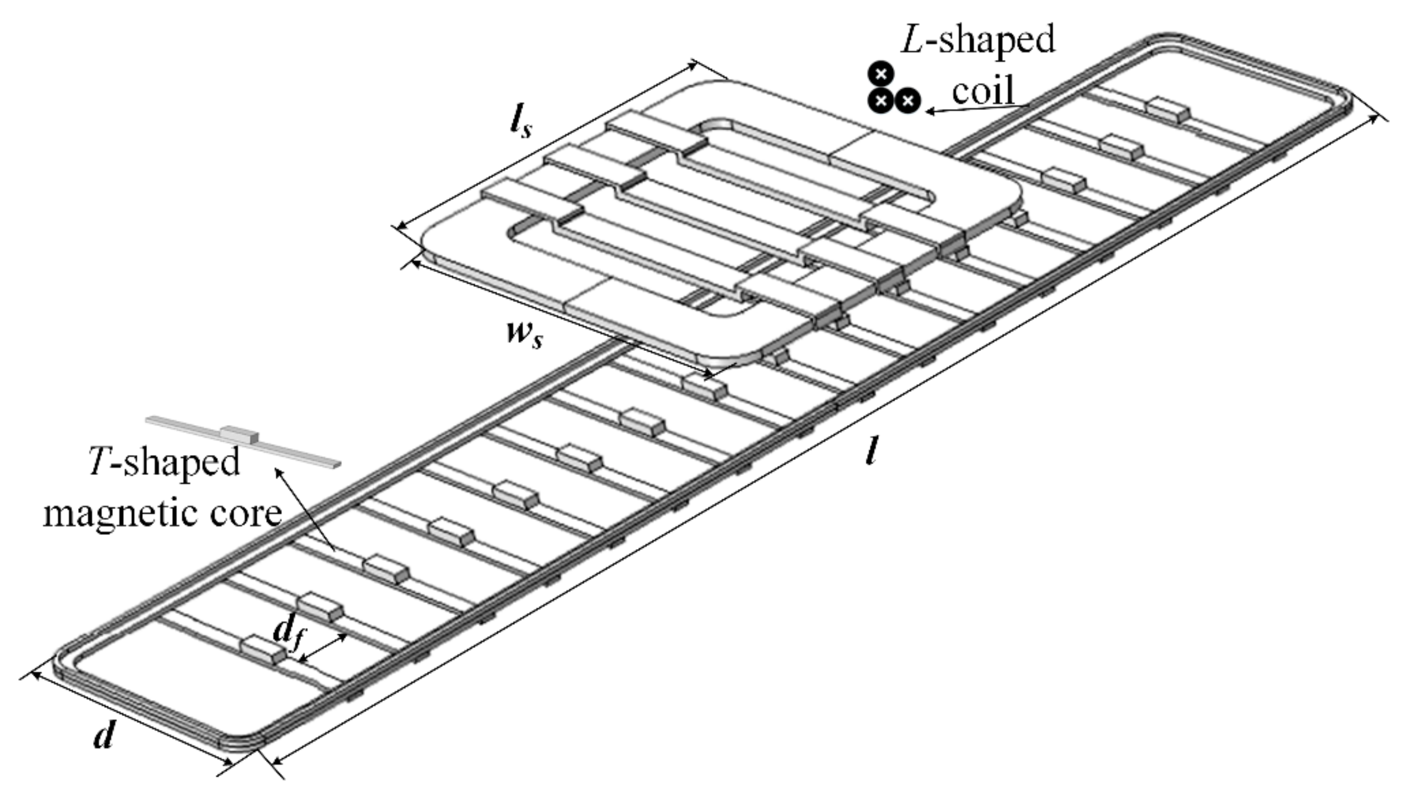
The designed supply coil in this paper uses three-turn wire to form two layers of coil, as shown in Figure 3. The lower layer is composed of two-turn counterclockwise wire, and the upper layer is composed of one-turn wire winding on the outermost side of the lower layer. The cross-section of the proposed supply coil is L-shaped; therefore, we call the proposed supply coil an L-shaped coil. In addition, the T-shaped magnetic core is used to enhance the magnetic flux density, in order to ensure the uniformity of the magnetic field on the plane of the secondary coil. The secondary coil uses the rectangular coil, and the magnetic core structure is designed as the bow shape to increase the coupling coefficient.
In order to verify whether the L-shaped coil can meet the power transmission requirements and safety requirements under the high-power supply, we used the multi-physics modeling and simulation software COMSOL (5.2, COMSOL Inc., Stockholm, Sweden) to analyze the characteristics of the magnetic coupler. For the convenience of comparison, the simulation model of the embeddable coil has already been established [16]. The specific parameters are shown in Table 1. l, d, N, and df represent the length, the width, the number of turns, and the distance between the magnetic core, respectively. ls and ws represent the length and the width of the secondary coil, respectively. N1 represents the turns of the switching region [16].
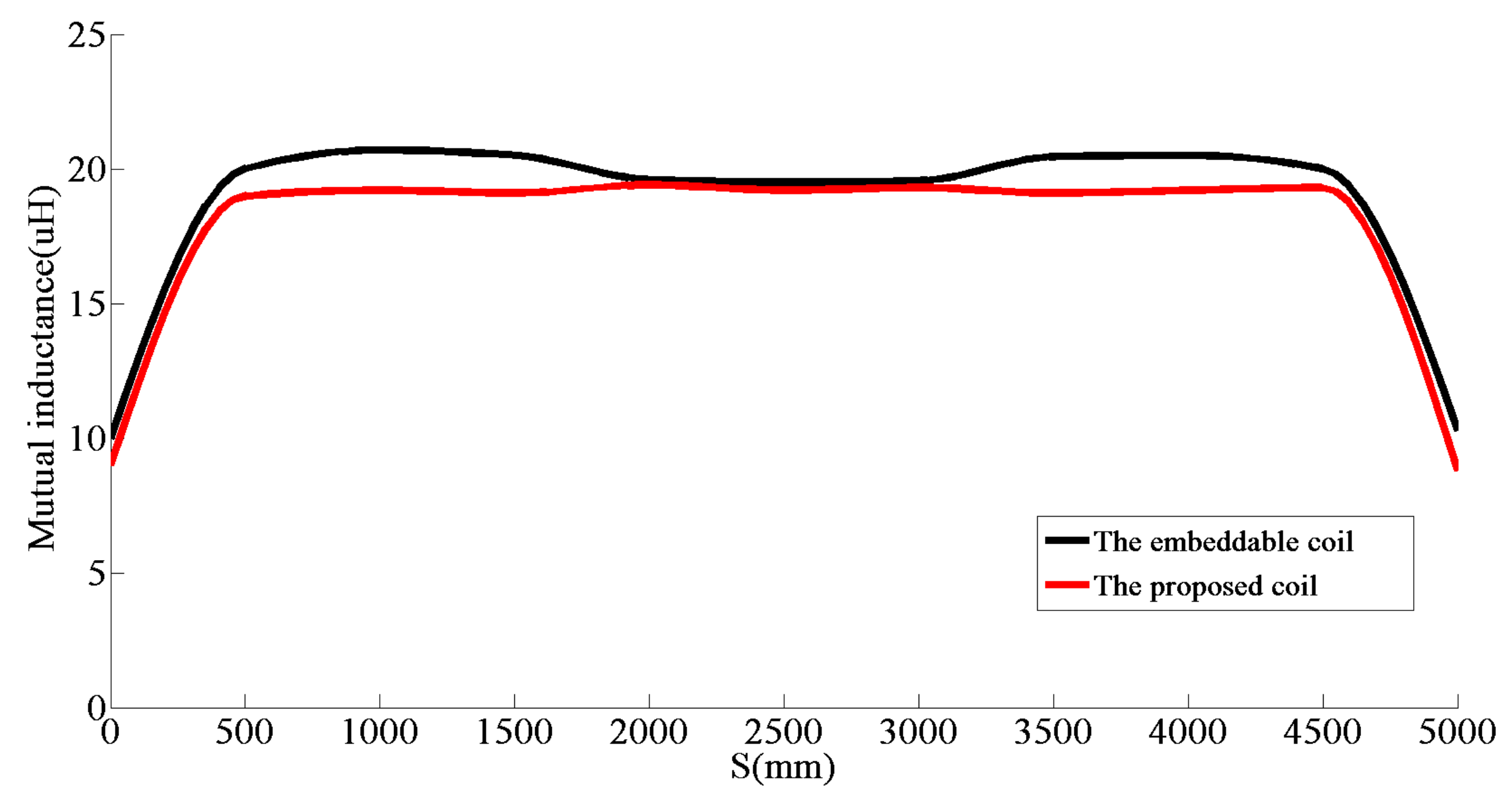
When the coupling distance between the supply coil and the secondary coil is set to 300 mm, the mutual inductance values of the two kinds of coils at different positions are simulated. The curve is drawn as shown in Figure 4. S represents the distance that the central point of the secondary coil moves with the supply coil.
In Figure 4, from 0–450 mm, the mutual inductance gradually increases when the secondary coil enters the supply coil. From 450–4550 mm, the secondary coil enters the supply coil completely, and the mutual inductance is basically stable. Between 4550–5000 mm, the mutual inductance gradually decreases when the secondary coil leaves the supply coil.
Based on the parameters of Table 1, the self-inductance of the L-shaped coil is 100 μH by the simulation, and the internal resistance is 0.3 Ω. For the embeddable coil, the self-inductance is 520 μH, and the internal resistance is 0.7 Ω. Therefore, the self-inductance of the embeddable coil is much larger than the L-shaped coil, but the mutual inductance of the L-shaped coil is substantially equal to the embeddable coil, as seen in Figure 4. The designed L-shaped coil greatly reduces self-inductance on the premise of ensuring the intensity of the excitation magnetic field, thereby reducing the voltage generated in the coil and ensuring the safety of the system. At the same time, the internal resistance of the L-shaped coil is reduced and the system efficiency is improved.
4.2. The Characteristic of the Magnetic Field
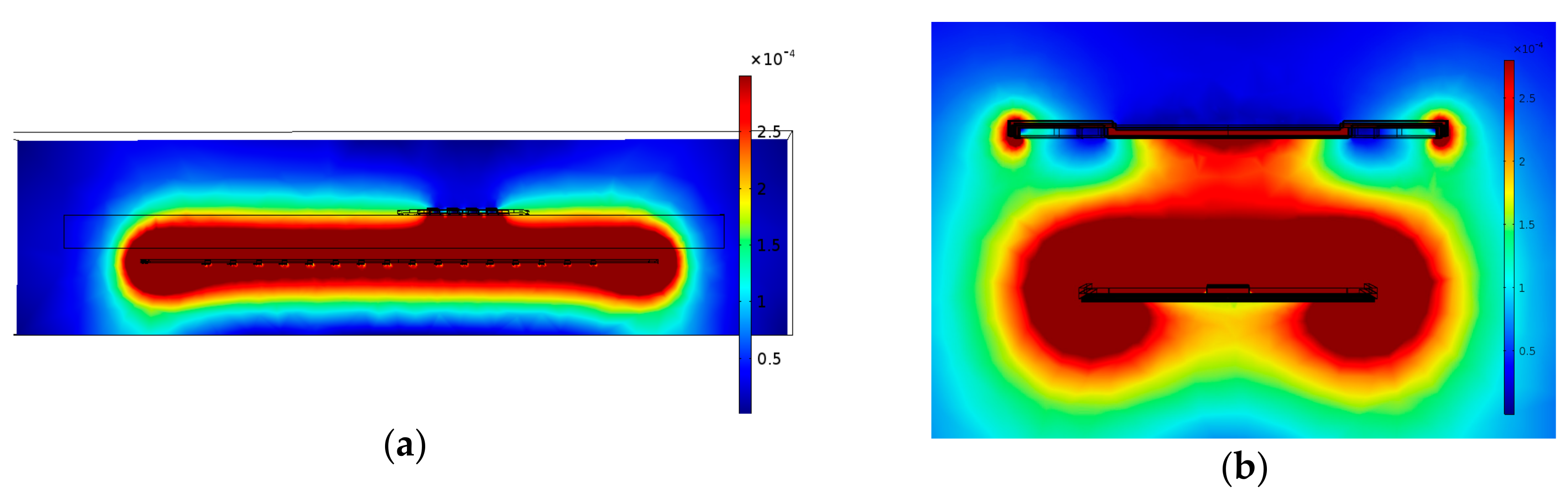
The distribution nephogram of the magnetic field intensity is shown in Figure 5. The color in the figure represents the magnetic field intensity of each region.
It can be seen from Figure 5a that the L-shaped coil can generate a uniform magnetic field, which ensures the power supply stability for multiple vehicles and improves the anti-offset of the system. In Figure 5b, the magnetic field generated by the L-shaped coil is mostly coupled to the secondary coil for power transmission, and a small part is leaked to the air to form the leakage magnetic field.
5. Simulation and Experiment
MATLAB (9.0, MathWorks, Natick, MA, USA) programming was used to verify the boundary condition of the load number. The parameters of the experimental system are shown in Table 2.
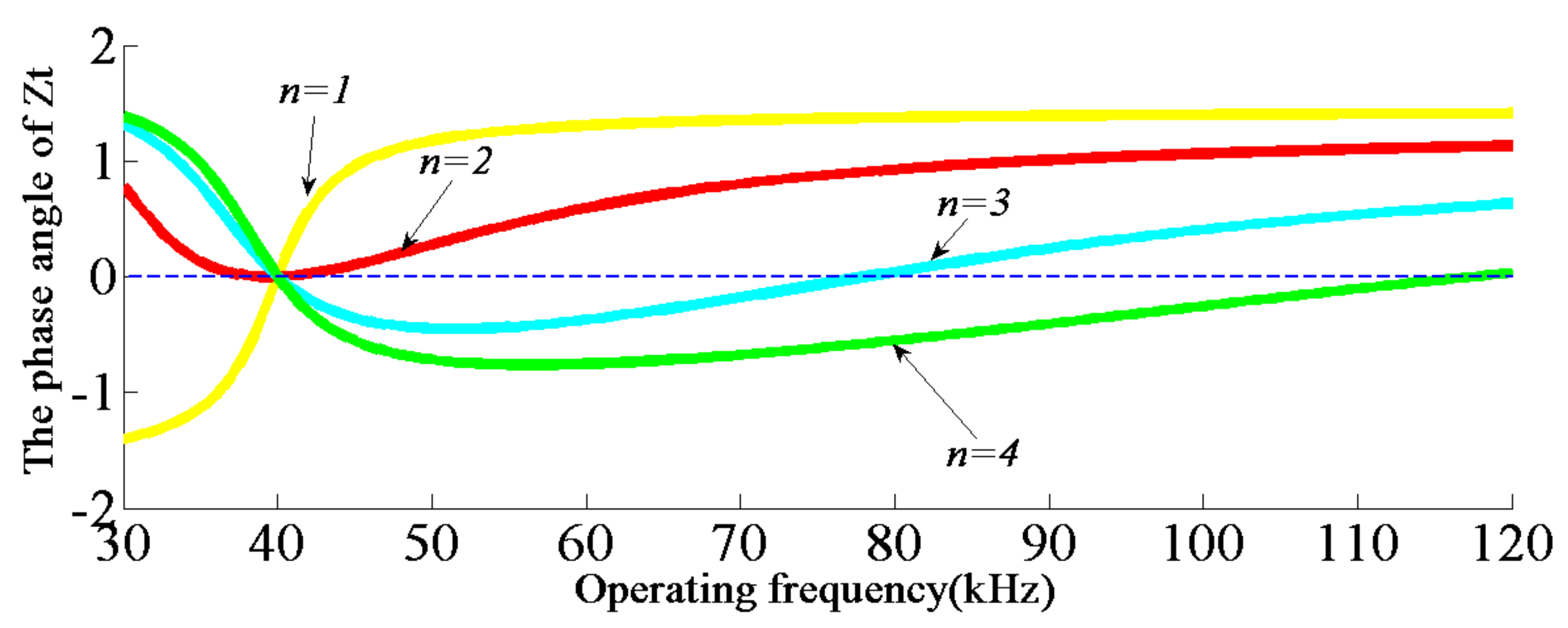
According to Equation (9), the boundary condition of the load number can be obtained: n ≤ 2.
Based on the parameters of Table 2, the phase frequency characteristic curve of Zt is shown in Figure 6.
It can be seen from Figure 6 that when n ≤ 2, the system has only one resonant frequency; when n > 2, the system has multiple resonant frequencies. It is worth noting that n = 2 is a critical point, corresponding to only one resonant frequency based on the simulation parameters in Table 2. As a result, n = 2 is a unique point in that the red curve in Figure 6 has both a positive and negative slope around the resonant frequency. The simulation results demonstrate the validity of the boundary condition established by Equation (9).
The magnetic coupler used in the experiment is shown in Figure 7. The structural parameters of the magnetic coupler are shown in Table 1. The distance between the primary coil and the secondary coil is 300 mm. In addition, the power inverter adopts a full bridge inverter.
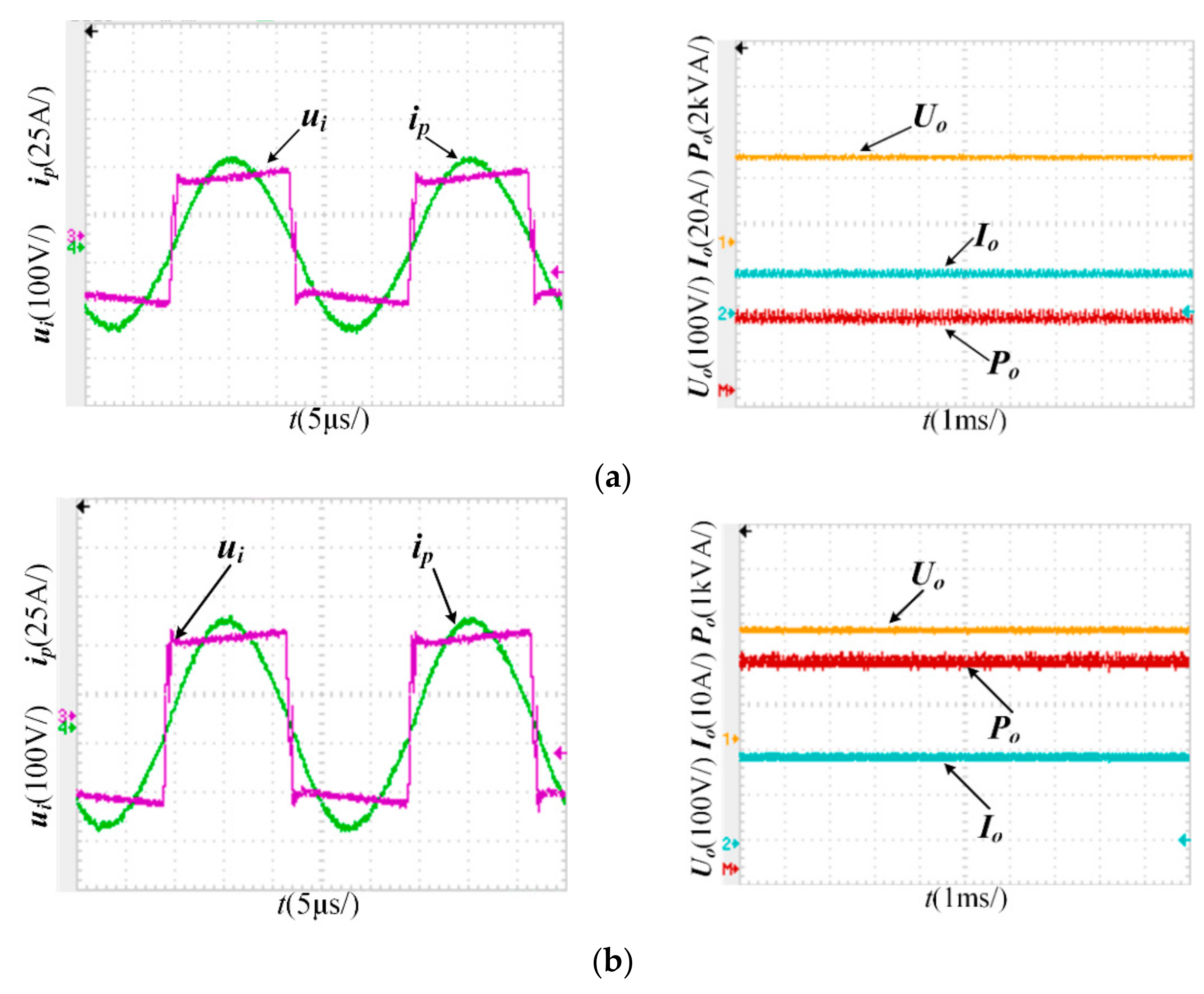
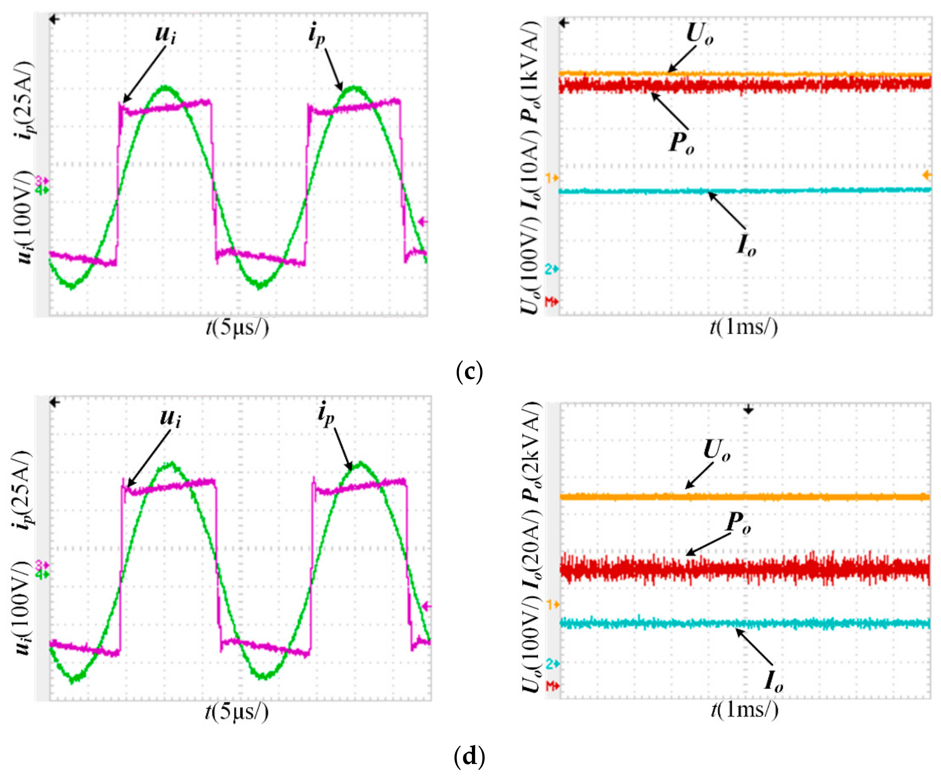
In order to test the operational state of the proposed L-shaped coil at different power points, different power levels were selected as the test points. The test waveforms are shown in Figure 8. ui, ip, Uo, Io, and Po represent the inverter output voltage, the resonant current, the output voltage, the output current, and the output power, respectively.
It can be seen from Figure 8 that the resonant frequency was maintained at 40 kHz when the system was operating at the above power points, indicating that the stability of the system is not affected by the change of the output power.
Based on the experimental results shown in Figure 8, the voltage generated in the coil and the coupling efficiency are shown in Table 3. The voltage Vr generated in the coil can be calculated as follows:
where Lp represents the self-inductance of the coil, and Ip represents the resonant current Root-Mean-Square (RMS) value.
It can be seen from Table 3 that the coupling efficiency of the proposed L-shaped coil is about 85%. The voltage of the L-shaped coil is much lower than the embeddable coil, which avoids the danger of the high-voltage breakdown. In addition, the voltage of the L-shaped coil is 1143.51 V in the case where the output power of 6.58 kW. The voltage is still at a low level, which indicates that the power of the system can be further improved, and ensures the safety of the high-power supply of the multi-load system.
6. Conclusions
In this paper, the multi-load mode of EV wireless supply system is studied. The influence of the load number on the system stability was analyzed, and the boundary condition of the load number was obtained. For the problem of a high-voltage breakdown caused by a high-power supply in multi-load mode, the L-shaped coil and the T-shaped magnetic core are proposed. The proposed structures can effectively reduce the self-inductance of the supply coil, on the premise of ensuring the intensity of the excitation magnetic field, thus ensuring the safety of the EV wireless supply system. The simulation and experimental results prove the correctness of the theoretical analysis. The research results of this paper have certain reference value for the design of EV wireless supply systems.
Author Contributions
C.J. and Y.S. proposed the structures, performed the simulations and experiments, and wrote the majority of the paper. Z.W. contributed to the discussion of the study and the related literatures. C.T. checked the results and the manuscript.
Funding
This research was funded by the National High-tech R&D Program (2015AA016201) and the Fundamental Research Funds of Chongqing (CSTC2013JCYJA0235).
Conflicts of Interest
The authors declare no conflict of interest.
References
- Wei, X.; Wang, Z.; Dai, H. A Critical Review of Wireless Power Transfer via Strongly Coupled Magnetic Resonances. Energies 2014, 7, 4316–4341. [Google Scholar] [CrossRef] [Green Version]
- Wang, C.S.; Covic, G.A.; Stielau, O.H. Power Transfer Capability and Bifurcation Phenomena of Loosely Coupled Inductive Power Transfer Systems. IEEE Trans. Ind. Electron. 2004, 51, 148–157. [Google Scholar] [CrossRef]
- Sun, L.; Tang, H.; Zhang, Y. Determining the Frequency for Load-Independent Output Current in Three-Coil Wireless Power Transfer System. Energies 2015, 8, 9719–9730. [Google Scholar] [CrossRef] [Green Version]
- Choi, S.; Huh, J.; Lee, W.Y. New Cross-Segmented Power Supply Rails for Roadway-powered Electric Vehicles. IEEE Trans. Power Electron. 2013, 28, 5832–5841. [Google Scholar] [CrossRef]
- Budhia, M.; Boys, J.T.; Covic, G.A. Development of a Single-Sided Flux Magnetic Coupler for Electric Vehicle IPT Charging Systems. IEEE Trans. Ind. Electron. 2013, 60, 318–328. [Google Scholar] [CrossRef]
- Tavakoli, R.; Pantic, Z. Analysis, Design and Demonstration of a 25-kW Dynamic Wireless Charging System for Roadway Electric Vehicles. IEEE J. Emerg. Sel. Top. Power Electron. 2017, 1–16. [Google Scholar] [CrossRef]
- Liu, C.; Ge, S.; Guo, Y.; Li, H. Double-LCL Resonant Compensation Network for Electric Vehicles Wireless Power Transfer: Experimental Study and Analysis. IET Power Electron. 2016, 9, 2262–2270. [Google Scholar] [CrossRef]
- Huh, J.; Lee, S.W.; Lee, W.Y. Narrow-Width Inductive Power Transfer System for Online Electrical Vehicles. IEEE Trans. Power Electron. 2011, 26, 3666–3679. [Google Scholar] [CrossRef]
- Wang, Z.; Wei, X.; Dai, H. Nested Three-Layer Optimization Method for Magnetic Coils used in 3 kw Vehicle-mounted Wireless Power Transfer System. IET Power Electron. 2016, 9, 2562–2570. [Google Scholar] [CrossRef]
- Pantic, Z.; Bai, S.; Lukic, S.M. Inductively Coupled Power Transfer for Continuously Powered Electric Vehicles. In Proceedings of the IEEE Vehicle Power Propulsion Conference, Dearborn, MI, USA, 7–10 September 2009; IEEE: Piscataway, NJ, USA, 2009; pp. 1271–1278. [Google Scholar]
- Jang, Y.J.; Suh, E.S.; Kim, J.W. System Architecture and Mathematical Models of Electric Transit bus System Utilizing Wireless Power Transfer Technology. IEEE Syst. J. 2016, 10, 495–506. [Google Scholar] [CrossRef]
- Ahn, D.; Hong, S. Effect of Coupling between Multiple Transmitters or Multiple Receivers on Wireless Power Transfer. IEEE Trans. Ind. Electron. 2013, 60, 2602–2613. [Google Scholar] [CrossRef]
- Lei, Y.; Zhang, J.; Song, K. Stability Analysis of Multi-load Inductively Coupled Power Transfer System. Trans. China Electron. Soc. 2015, 30, 187–192. [Google Scholar]
- Wesemann, D.; Witte, S.; Michels, J.S. Effects of multiple loads in a contactless, inductively coupled linear power transfer system. In Proceedings of the International Conference on Electrical and Electronics Engineering, Bursa, Turkey, 5–8 November 2009; IEEE: Piscataway, NJ, USA, 2009; pp. 54–59. [Google Scholar]
- Shin, J.; Shin, S.; Kim, Y. Design and Implementation of Shaped Magnetic-resonance-based Wireless Power Transfer System for Roadway-powered Moving Electric Vehicles. IEEE Trans. Ind. Electron. 2014, 61, 1179–1192. [Google Scholar] [CrossRef]
- Su, Y.G.; Zhang, S.; Hu, C.; Tang, C.S.; Zhou, W. An Embeddable Transmitter Coil Applied to Electric Vehicles Powered by IPT System. Int. J. Appl. Electromagnet. Mech. 2016, 50, 627–636. [Google Scholar] [CrossRef]
- Liu, S.Q.; Tan, J.P.; Xue, S.H. Analysis on Coupling Mechanism Characteristics of Multi-load Wireless Power Transmission System. Autom. Electr. Power Syst. 2016, 40, 84–90. [Google Scholar]
- Raabe, S.; Covic, G.A. Practical Design Considerations for Contactless Power Transfer Quadrature Pick-ups. IEEE Trans. Ind. Electron. 2013, 60, 400–409. [Google Scholar] [CrossRef]
- Li, H.C.; Wang, K.P.; Huang, L. Dynamic Modeling Based on Coupled Modes for Wireless Power Transfer Systems. IEEE Trans. Power Electron. 2015, 30, 6245–6353. [Google Scholar] [CrossRef]
- Tang, C.S.; Sun, Y.; Dai, X.; Wang, Z.H.; Su, Y.G.; Hu, A.G. Analysis of Multiple Resonant Operating Points and Their Autonomous Oscillation Stabilities in Inductive Power Transfer System. Acta Phys. Sin. 2011, 60, 1–9. (In Chinese) [Google Scholar]
Figure 1.
The topology of the wireless supply system.
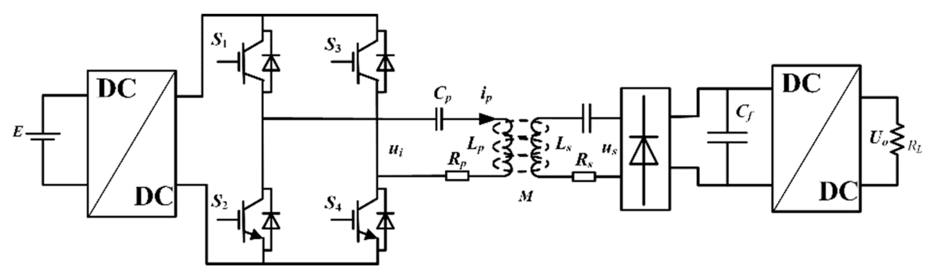
Figure 2.
The equivalent circuit model of the multi-load system.
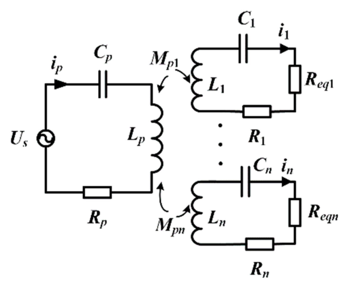
Figure 3.
The structure of the magnetic coupler.

Figure 4.
The simulation curve of mutual inductance.

Figure 5.
The distribution nephogram of the magnetic field intensity: (a) the vertical section along the x-axis; (b) the vertical section along the y-axis.
Figure 5.
The distribution nephogram of the magnetic field intensity: (a) the vertical section along the x-axis; (b) the vertical section along the y-axis.

Figure 6.
The phase frequency characteristic curve of Zt.

Figure 7.
The magnetic coupler.
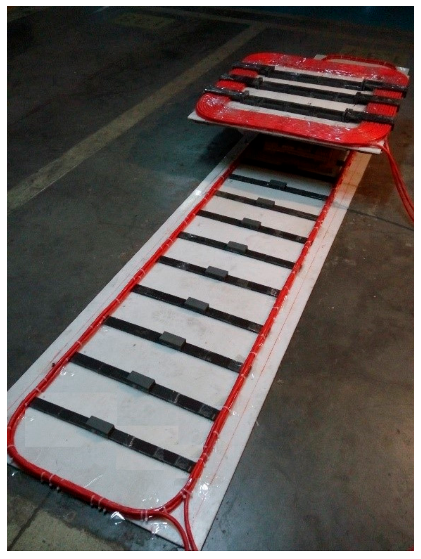
Figure 8.
The test waveforms of the L-shaped coil: (a) 3.17 kW; (b) 4.58 kW; (c) 5.81 kW; (d) 6.58 kW.
Figure 8.
The test waveforms of the L-shaped coil: (a) 3.17 kW; (b) 4.58 kW; (c) 5.81 kW; (d) 6.58 kW.

Table 1.
The parameters of the coils.
| The L-Shaped Coil | The Embeddable Coil | The Secondary Coil | |||
|---|---|---|---|---|---|
| Parameters | Values | Parameters | Values | Parameters | Values |
| l/mm | 5000 | l/mm | 5000 | ls/mm | 900 |
| d/mm | 700 | d/mm | 700 | ws/mm | 700 |
| N | 3 | N | 6 | N | 20 |
| df/mm | 180 | N1 | 17 | - | - |
Table 2.
Parameters of the experimental setup.
| Parameters | Values |
|---|---|
| Supply coil Lp | 100 μH |
| Internal resistance of supply coil Rp | 0.3 Ω |
| Primary resonant capacitor Cp | 158 nF |
| Secondary coil Li | 480 μH |
| Internal resistance of secondary coil Ri | 0.5 Ω |
| Secondary resonant capacitor Ci | 33 nF |
| Equivalent load resistance Reqi | 14.5 Ω |
| Operating frequency f | 40 kHz |
Table 3.
The coupling efficiency and the voltage.
| Output Power (kW) | Coupling Efficiency | The Voltage Generated in the L-Shaped Coil (V) | The Voltage Generated in the Embeddable Coil (V) |
|---|---|---|---|
| 3.17 | 84.83% | 789.14 | 4103.53 |
| 4.58 | 84.81% | 942.45 | 4900.74 |
| 5.81 | 84.91% | 1068.11 | 5554.17 |
| 6.58 | 85.07% | 1143.51 | 5946.25 |
© 2018 by the authors. Licensee MDPI, Basel, Switzerland. This article is an open access article distributed under the terms and conditions of the Creative Commons Attribution (CC BY) license (http://creativecommons.org/licenses/by/4.0/).
Share and Cite
MDPI and ACS Style
Jiang, C.; Sun, Y.; Wang, Z.; Tang, C. Multi-Load Mode Analysis for Electric Vehicle Wireless Supply System. Energies 2018, 11, 1925. https://doi.org/10.3390/en11081925
AMA Style
Jiang C, Sun Y, Wang Z, Tang C. Multi-Load Mode Analysis for Electric Vehicle Wireless Supply System. Energies. 2018; 11(8):1925. https://doi.org/10.3390/en11081925
Chicago/Turabian StyleJiang, Cheng, Yue Sun, Zhihui Wang, and Chunsen Tang. 2018. "Multi-Load Mode Analysis for Electric Vehicle Wireless Supply System" Energies 11, no. 8: 1925. https://doi.org/10.3390/en11081925
Note that from the first issue of 2016, this journal uses article numbers instead of page numbers. See further details here.