Article

Adaptive Virtual Impedance Droop Control Based on Consensus Control of Reactive Current

1
Guangxi Key Laboratory of Power System Optimization and Energy Technology, Guangxi University, Nanning 530004, China
2
Department of Electrical and Computer Engineering & Computer Science, University of New Haven, West Haven, CT 06516, USA
*
Author to whom correspondence should be addressed.
Energies 2018, 11(7), 1801; https://doi.org/10.3390/en11071801
Submission received: 25 May 2018 / Revised: 21 June 2018 / Accepted: 2 July 2018 / Published: 10 July 2018
(This article belongs to the Section F: Electrical Engineering)

Abstract

:
It is difficult to achieve accurate distribution of reactive power based on conventional droop control due to the line impedance mismatch in an islanded microgrid. An adaptive virtual impendence method based on consensus control of reactive current is proposed in this paper. A distributed control structure without the central controller has been established. In this structure, each distributed generation unit (DG) is an independent agent, one-way communication is used between the adjacent DGs, and the reactive power sharing is equivalent to a problem of reactive power current consensus. It has been proven that the system is asymptotically stable under the proposed control strategy. When the adjacent DG’s reactive power is not proportionally distributed, the current weight error term will generate a virtual impedance correction term through the proportional-integral controller based on the reactive current consensus control strategy, thus introducing adaptive virtual impedance to eliminate mismatches in output impedance between DGs. Reactive power auto-proportional distribution can be achieved without knowing the line impedance. At the same time, the power control loop is simplified and the virtual impedance compensation angle is employed to compensate the decreased reference voltage magnitude and varied phase angle due to the introduction of the virtual impedance, so the stability of the system can be improved. Finally, the correctness and effectiveness of the proposed strategy are verified by modeling analysis and microgrid simulations.

1. Introduction

The increasing demand for renewable energy-based power generation systems consisting of inverters necessitates the design of sophisticated inverter control systems [1,2,3]. Apart from ensuring the quality of power output, the inverter control system should be able to coordinate the operation of multiple distributed generators (DGs) and distribute power to loads according to the capacity of each power source [4]. Research on energy management, reliability of component, coordination, and optimization of renewable energy in hybrid microgrids has been conducted [5,6,7,8,9]. The droop control system, based on the droop characteristic of synchronous generators, offers the benefits of sparse communication and ‘plug and play’. Therefore, it is widely used in microgrid control [10,11,12]. While the P-f droop control enables accurate sharing of active power during real-world microgrid operation, the Q-V droop control exhibits poor performance with regards to reactive power sharing because it is susceptible to the influence of line impedance.
In order to improve the power sharing accuracy for any micro-grid in island-mode, the authors of [13] proposes a P-V control scheme to achieve accurate sharing of active power by adjusting the droop coefficient. Although accurate power sharing can be achieved by increasing the droop gain, large droop gain will render the system less stable [14]. References [15,16] introduce the integral component into the power control loop to eliminate the power steady-state error. Reference [17] proposes a method that injects additional signals. As this method involves complex signal generation and processing, it is difficult to implement in a microgrid containing multiple DGs. Reference [18] proposes a “Q-V dot droop” method, but the reactive power cannot be accurately shared when local loads are connected. A reactive power disturbance term is introduced into the P-f droop equation, with the aim of reducing the reactive power sharing error by manipulating the active power [19]. However, this method affects the active power and the stability of the system frequency.
In recent years, “virtual impedance” theory has become widely used to solve the problem of reactive power distribution. “Virtual impedance” means adding an output impedance adjustment module outside the closed-loop control of the inverter. The influence of the line impedance and device difference on the power distribution is suppressed by the virtual impedance, and the problem of increased volume and cost caused by the addition of the current-sharing inductor is avoided. Reference [20] proposes a kind of coupled virtual impedance, realizes the power distribution in the hybrid microgrid and reduces the point of common coupling (PCC) harmonic content by adjusting the coupled virtual impedance. Similarly, reference [21] uses the virtual impedance to solve the problem of power allocation and harmonic suppression in droop control. However, this method requires knowledge of the line impedance in advance. In [22] a new topology structure is proposed to implement intelligent droop control, thereby improving the power distribution characteristics. In [23,24,25], the equivalent output impedance of each micro-source is determined by adjusting the closed-loop parameters so that the virtual impedance becomes the dominant parameter. Thus, the circulating current between micro-sources is effectively suppressed, thereby improving the accuracy of power sharing. However, reference [23,24,25,26] ignore the problem of line impedance mismatch. To further improve the power sharing accuracy, reference [27,28,29] propose a virtual impedance method based on the line impedance estimation. The authors of [30] proposes an adaptive virtual impedance method to achieve adaptive adjustment of virtual impedance by integrating the voltage drop between DGs. However, as this method adopts a centralized control scheme, it depends heavily on the reliability of the communication network. In [31,32], secondary control is used to improve the sharing of active and reactive power. Although accurate results can be achieved, its control strategy is complicated and based on centralized control, so the system still relies on the reliability of the communication network. References [33,34] apply multi-agent theory to the adjustment of virtual impedance. This method only requires communication between adjacent micro-sources and is, therefore, characterized by higher system reliability. However, the analysis in [33,34] did not discuss how the introduction of virtual impedance leads to phase angle offset in the outer loop reference voltage.
In this paper, an adaptive virtual impedance control strategy based on reactive current consensus control is proposed to improve the accuracy of reactive power distribution. In this method, each DG unit is regarded as an independent agent. This method only requires communication between adjacent DGs without the need for a central controller. By obtaining the virtual impedance correction value through the consensus control of reactive current, a virtual impedance is introduced to compensate for the output impedance mismatch. The power control loop is also streamlined to minimize the voltage sag of the alternating current (AC) bus without affecting the droop characteristics. Meanwhile, a virtual impedance compensation angle θv is introduced to compensate for the phase angle offset of the micro-source reference voltage so as to improve the stability of the system. Finally, the effectiveness of the proposed method was verified through simulation.

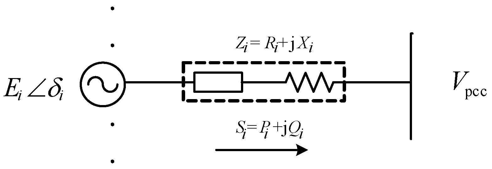
2. Power Sharing with Droop Control

The micro-source equivalent structure in the microgrid is shown in Figure 1, in which the DG is connected to the common terminal Vpcc through an equivalent impedance Z. The droop control in islanded mode enables the DG unit to operate independently without communication. It can be worked out from Figure 1 that the active and reactive powers injected into the common point by the DG unit are given by:
P i = V pcc R i 2 + X i 2 [ R i ( E i cos δ i V pcc ) + X i E i sin δ i ]
Q i = V pcc R i 2 + X i 2 [ X i ( E i cos δ i V pcc ) R i E i sin δ i ]
where E i is the output voltage amplitude of the inverter i; V pcc is the voltage of the coupling node; δ i is the power angle between E i and V pcc . In a real-world low-voltage microgrid, the line impedance is resistive and there exists coupling between active and reactive powers, making it impossible for the system to distribute power accurately. The control method based on the introduction of virtual impedance offers a solution to this problem. Usually, the virtual impedance is inductive and treated as the dominant parameter. Considering that X i > > R i and δ i is very small:
δ i X i P i E i V pcc
E i V pcc X i Q i V pcc
The conventional droop control model is defined as the following equations:
ω i = ω 0 m i P i
E i = E 0 n i Q i
where E 0 and ω 0 are no-load voltage and frequency, respectively, m i and n i are the active and reactive droop coefficients of inverter I, respectively.
In [26], the virtual impedance is realized by adjusting the parameters of the double-loop PI controller. The output voltage is given by [26]:
v o = G ( s ) v ref + Z o ( s ) i o ( s )
where G ( s ) is voltage gain, and Z o ( s ) is the equivalent output impedance which can be calculated using Equation (8):
Z o ( s ) = L s 2 L C s 3 + K V dc 2 C s 2 + ( 1 + K K vp V dc 2 ) s + K K vi V dc 2
It can be seen from Equation (8) that the equivalent output impedance is not only related to the filter parameters L and C, but also influenced by the PI controller. Using the design parameters stated in [26] (see Table 1), the equivalent output impedance is inductive, and the influence of the line impedance can be ignored. The output impedance Bode diagram is shown in Figure 2.
It can be seen by analyzing Figure 2, while the output impedance of the inverter can be inductive at 50 Hz, the output impedance can only be about 0.01 mΩ, which limits the range of the line impedance parameters. That is, only when a relatively small line impedance is chosen, the dominant status of the output impedance can be ensured. Moreover, changing the double-loop PI controller parameters can only affect small adjustments to the output impedance, and if consideration is solely given to the design of the output impedance when choosing PI control parameters, the system stability margin will inevitably be affected negatively, resulting in reduced stability.
In this study, a new virtual impedance Z V , i using direct series connection is designed. Thus, the system output impedance is given by:
Z i = Z l i n e , i + Z V , i = Z l i n e , i + Z V , i + Z a d p , i
where Z i is the equivalent output impedance of the micro-source, Z l i n e , i is the line impedance and Z V , i is the virtual impedance consisting of the static virtual impedance Z V , i and the adaptive virtual impedance Z a d p , i .The static virtual impedance always ensures the system impedance is mainly inductive. The adaptive virtual impedance automatically adjusts the virtual impedance magnitude according to the equivalent output impedance of the adjacent DG. Hence, accurate reactive power sharing is achieved by eliminating the output impedance mismatch. This method does not rely on the adjustment of the double-loop control parameters of the system and, therefore, allows for a greater range of impedance adjustment compared with the previous method.

3. Reactive Power Sharing Based on Reactive Current Control

In [35], it is noted that in the typical “power-voltage-current” closed-loop droop control, the power control loop increases the complexity of the system and affects its dynamic characteristics due to the power calculations required. A method to realize droop control by controlling active and reactive currents was proposed in [36]. The key merit of this control method is that the system is incapable of yielding infinitely impulse current when short circuit occurs ( E i = 0 ). This paper applies this method to the design of adaptive virtual impedance.
Active and reactive currents I a i and I r i of equivalent impedance Z can be calculated as:
I a i = P i V pcc = R i ( E i cos δ i V pcc ) + X i E i sin δ i R i 2 + X i 2
I r i = Q i V pcc = X i ( E i cos δ i V pcc ) R i E i sin δ i R i 2 + X i 2
Considering that X i > > R i , cos δ i 1 , sin δ i δ i , Equations (3) and (4) can be rewritten as:
δ i X i I a i E i
E i V pcc X i I r i
The active current and reactive current droop characteristics are defined as:
ω i = ω 0 k m i I a i
E i = E 0 k n i I r i
In order to satisfy the proportional distribution of the load reactive power, the droop coefficient and reactive power should be designed to be inversely proportional [30]:
k n 1 Q 1 = k n 2 Q 2 = = k n n Q N
When using reactive current control, the following equation should be satisfied:
k n 1 I r 1 = k n 2 I r 2 = = k n N I r N
Substituting (13) into Equation (15), the reactive current flow from the DGi to load is obtained as:
k n i I r i = E 0 V pcc X i k n i + 1
To satisfy Equation (17), the following equation can be derived from Equation (18):
X 1 k n 1 = X 2 k n 2 = = X N k n N
As it can be seen in Equation (19) that in order to achieve accurate reactive power distribution, k n i should be proportional to the line reactance Xi. Considering Equation (17), the line reactances must be designed to be inversely proportional to the reactive current, respectively:
X 1 I r 1 = X 2 I r 2 = = X N I r N
where X i Z i as previously described.

4. Adaptive Virtual Impedance Control Strategy Based on Consensus Control

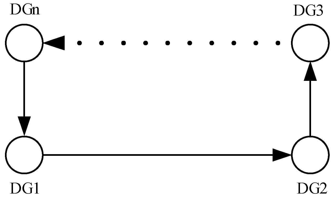
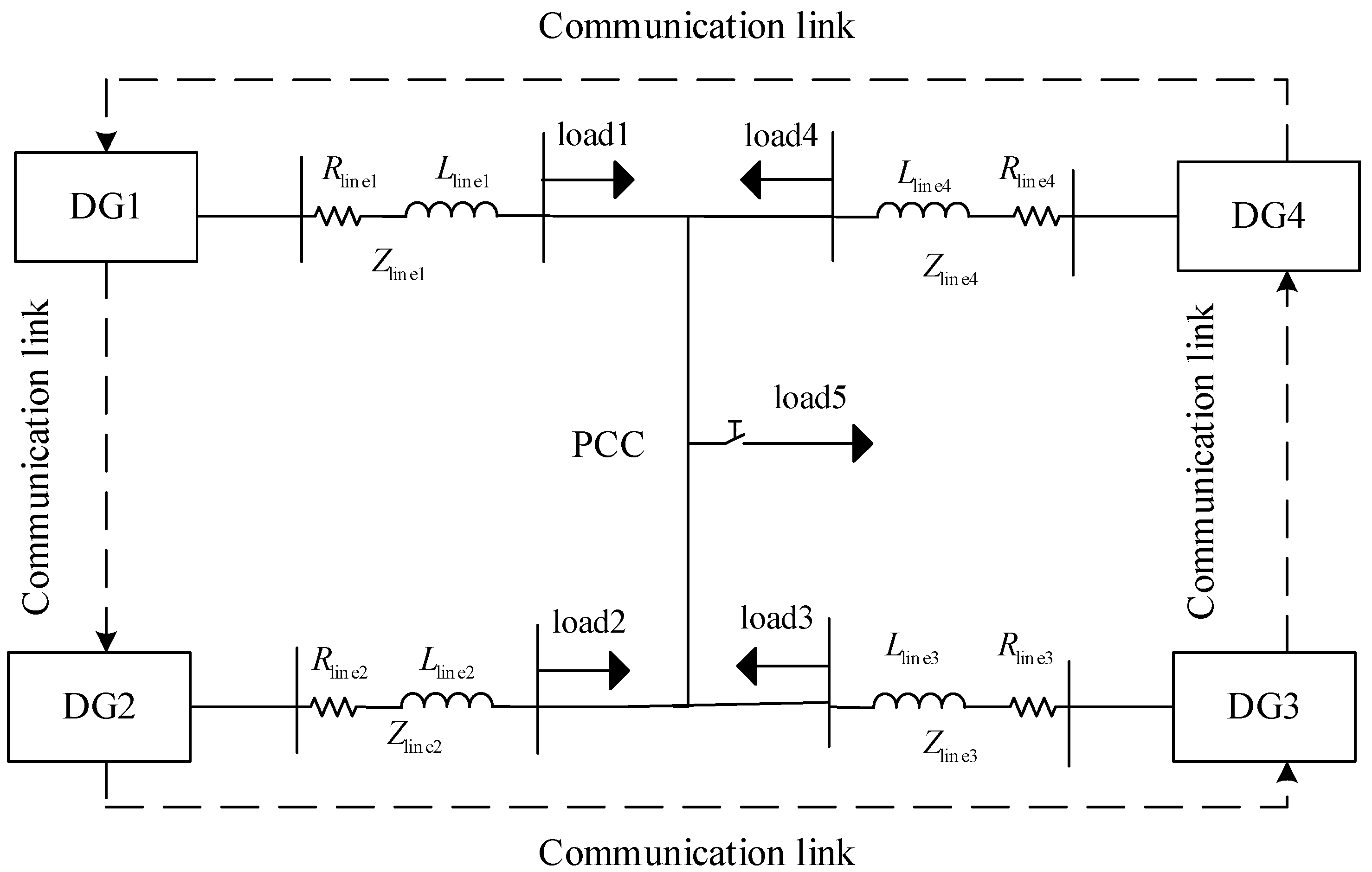
4.1. Microgrid Communication Topology

If each DG in the microgrid is regarded as a node, and the communication links between the DGs are equated to edges, the topological model of the entire microgrid can be represented by a digraph (directed graph). Usually, a digraph G refers to an ordered triplet (V(G), E(G), A(G)), where V ( G ) = ( v 1 , v 2 , v N ) is a set of non-empty nodes, E ( G ) V ( G ) × V ( G ) is an edge set that edges of points with communication associated and A(G) is a correlation function which is typically an associated adjacency matrix A ( G ) = [ a i j ] N × N . In this paper, the digraph is assumed to be time-invariant, i.e., A(G) is a constant. The edge from node j to node i is denoted as ( v j , v i ) . If ( v j , v i ) E ( G ) , then a i j = 1 and node j is called a neighbor of node i. The set of all nodes that satisfy the above condition is denoted as N i = { j | ( v j , v i ) ε } . If ( v j , v i ) E ( G ) , then a i j = 0 . The Laplacian matrix is defined as L = D A , where D is the indegree matrix denoted as D = diag { d i } N × N , d i = j N i a i j . Many properties of the digraph are manifested in the above matrix. In this paper, adjacent nodes in the DG network are treated as follows: Node i can obtain information from node j but node j cannot obtain information from node i, with both the indegree and outdegree of each node set to 1, as shown in Figure 3. Therefore, the communication between the DGs is regarded as a one-way distributed loose communication. Moreover, the network topology in Figure 3 contains a directional spanning tree. When a communication line is faulty, the system still maintains high reliability and the sparse network structure reduces the communication cost.

4.2. Consensus Control

According to the consensus control strategy, in order to control the reactive current, the k n i I r i term of each DG should be assigned the same value as shown in Equation (17). Thus, the reactive power distribution based on consensus control of the reactive current can be transformed into the synchronization problem of the first-order linear multi-agent system [37]. Linearization of Equation (17) can be formulated as:
k n 1 I ˙ r 1 = k n 2 I ˙ r 2 = = k n N I ˙ r N = u I r i
According to the consensus control theory, u I r i is an adjoint control term. If the term is not 0, there is a reactive power deviation between the local and its neighbors:
u I r i = C n I r e k n i I r i
where C n I r is the coupling gain and e k n i I r i is the reactive current weight error between local and adjacent DG units:
e k n i I r i = j = N i a i j ( k n i I r i k n j I r j )
where aij is an adjacency matrix element that reflects the connection of DGs. Then the matrix form of the consensus control system can be expressed as:
k n I ˙ r = u I r
u I r = C n I r e k n I r
e k n I r = L k n I r
where the above variables are defined as k n I ˙ r = [ k n 1 I ˙ r 1   , k n 2 I ˙ r 2   , k n N I ˙ r N ] T , u I r = [ u I r 1 , u I r 2 ,     u I r N ] T , e k n I r = [ e k n 1 I r 1 ,   e k n 1 I r 1 ,   e k n N I r N ] T , k n I r = [ k n 1 I r 1 , k n 2 I r 2 ,     k n N I r N ] T .
The stability of the proposed control system is proven below. In this paper a simple quadratic Lyapunov function is used to show the stability of the system. However, [38] indicates that for some applications using a non-quadratic Lyapunov function can also lead to a better performance.
Constructing Lyapunov energy function as:
V k n I r = 1 2 e k n I r T P e k n I r
where P = P T , P is a positive definite matrix. The following equation can be obtained from Equation (27):
V ˙ k n I r = e k n I r T P e ˙ k n I r = e k n I r T P L k n I ˙ r
Combining the equations above, the following equation can be obtained:
V ˙ k n I r = e k n I r T P e ˙ k n I r = e k n I r T P L u I r
Defining HL, Substituting Equation (25) into (29), and the following equation is described as:
V ˙ k n I r = C n I r e k n I r T P H e k n I r = 1 2 C n I r e k n I r T ( P H + H T P ) e k n I r
This paper considers the configuration of four different rated power DG units. Letting P = diag{1, 1, 1, 1}, then the Laplacian of the communication topology is:
L = D A = [ 1 1 0 0 0 1 1 0 0 0 1 1 1 0 0 1 ]
Then:
P H + H T P = [ 2 1 0 1 1 2 1 0 0 1 2 1 1 0 1 2 ]
The matrix P H + H T P is positive definite, so V ˙ k n I r < 0 , using Lyapunov’s second law, the system is determined to be asymptotically stable.

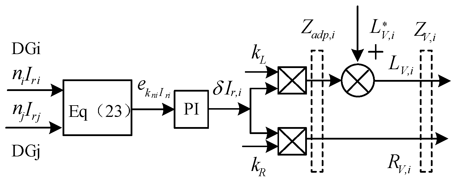
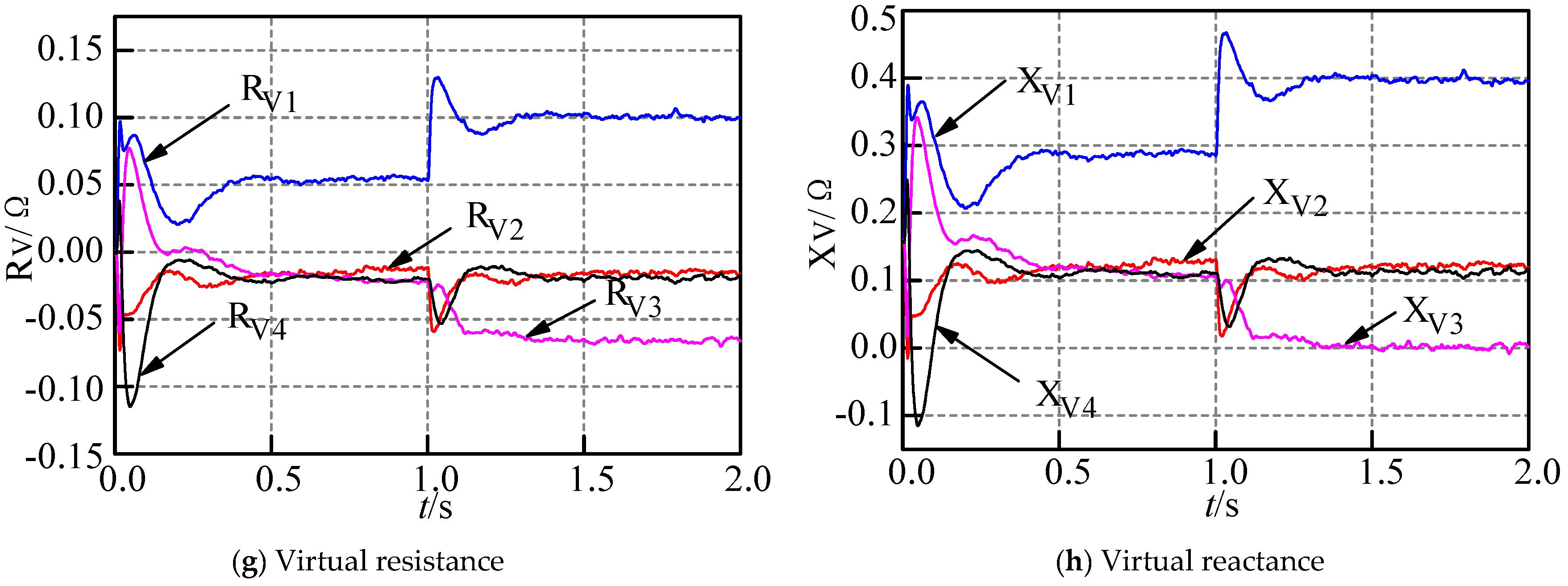
4.3. Method of Realizing Virtual Impedance

From Figure 4, the following equation can be obtained:
L V , i = L V , i + k L δ I r , i
R V , i = k R δ I r , i
where Z V , i = R V , i + j ω i L V , i is the equivalent virtual impedance, k L and k R are the proportional gains (which are used to adjust the value of the adaptive virtual impedance), L V , i represents the static virtual inductance and the reactive current error term e k n i I r i is processed by the proportional integral controller (PI) to yield the virtual impedance correction term δ I r , i .
When the reactive power output from DGs are out of proportion, the current error term will be generated according to Equation (23). After the error term is processed by the proportional integral controller, the virtual impedance correction term will be generated and the adaptive virtual impedance of the system will be adjusted accordingly. In this paper, Section 3 indicates that the magnitude of the system impedance should be adjusted so that it is inversely proportional to the reactive load shared.
As previously discussed, since the equivalent output impedance Z o ( s ) of the micro-source mentioned in [26] is only 0.01 mΩ, the adjustment range is limited. In this paper, the static virtual impedance Z V ( s ) is connected in series and Z V ( s ) > > Z o ( s ) . In this case, the equivalent virtual impedance of the micro-source becomes the dominant parameter. Thus, by adjusting the value of the adaptive virtual impedance Z a d p ( s ) , the magnitude of the output impedance can be changed to achieve proportional sharing of reactive power.
After the introduction of the virtual impedance, the equivalent circuit of the DG is shown in Figure 5.
Taking the virtual impedance Z V ( s ) = Z a d p ( s ) + Z V ( s ) to be inductive, the expression for the micro-source equivalent virtual impedance is shown in Equation (35), where the gain and phase angle of the transfer function G(s) at the fundamental frequency are 1 and 0, respectively. The droop control parameters are shown in Table 2 and the Bode plot of the micro-source equivalent output impedance is shown in Figure 6.
Z V ( s ) = G ( s ) Z V ( s ) + Z o ( s ) = L V L C s 4 + K V dc 2 L V C s 3 + ( L + L V + K K vp V dc 2 L V ) s 2 + K K vi L V V dc 2 s L C s 3 + K V dc 2 C s 2 + ( 1 + K K vp V dc 2 ) s + K K vi V dc 2
It can be determined by analyzing Figure 6 that the design method proposed in this paper ensures that the virtual impedance is inductive when the fundamental frequency is 50 Hz. Meanwhile, the magnitude of the virtual impedance reaches 0.252 Ω. Thus, a larger impedance adjustment range is available, compared with that offered by the design method proposed in [26].

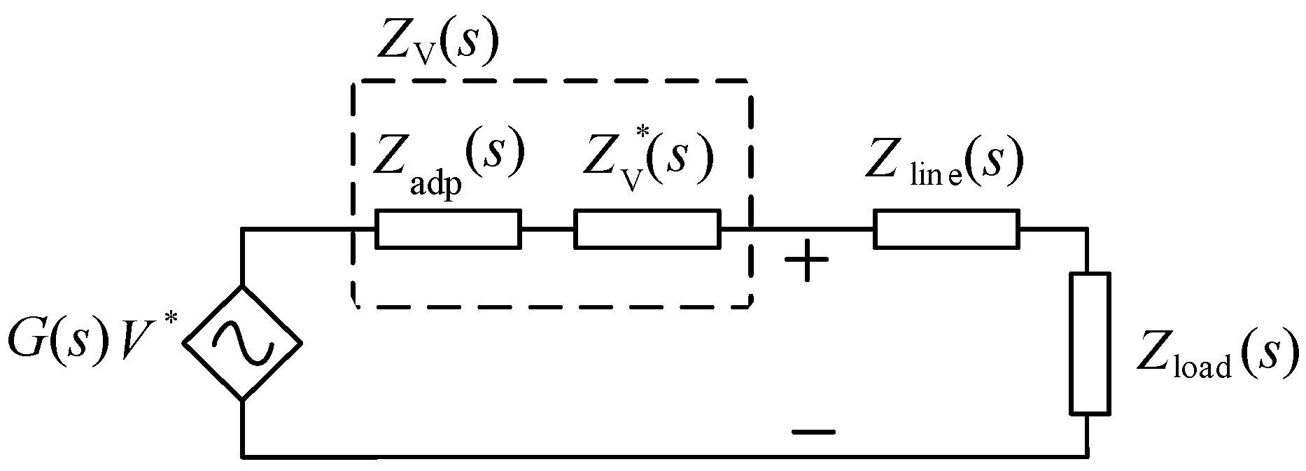
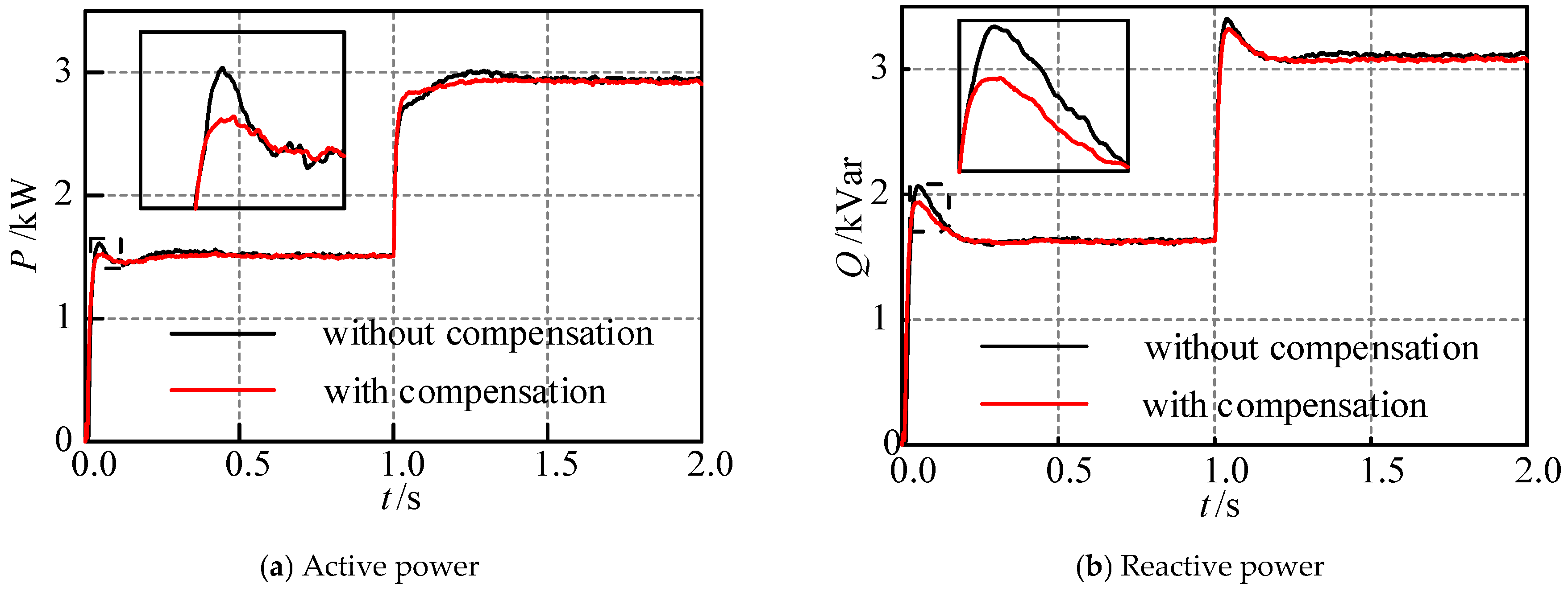
5. Reference Voltage Phase Shift Compensation Using Virtual Impedance Angle

The voltage drop V v i _ d and V v i _ q caused by the introduction of virtual impedance in synchronous reference frame can be expressed as (36) and (37)
V v i _ d = I d i R V , i I q i ω L V , i
V v i _ q = I q i R V , i + I d i ω L V , i
where I d i and I q i are active and reactive currents respectively. The new voltage reference is calculated by the following equation
V dnewref = V dref V v i _ d
V qnewref = V qref V v i _ q
where V dref and V qref are the initial reference voltage signals, so the change in control loop voltage in the dq-coordinate system as a result of introducing virtual impedance is depicted in Figure 7:
From Figure 7 one can calculate the virtual angle added by the virtual impendence, which is between V dqnewref and V dqref . Equation (40) describes the relation between V dqnewref and V dqref .
[ V dnewref V qnewref ] = [ cos θ v sin θ v sin θ v cos θ v ] [ V dref V qref ]
After developing Equation (40) θ v can be calculated using Equation (41) from reference [39].
θ v = arcsin ( V qref V qnewref V dref + V qref )
The change in the angle at different virtual impedances is shown in Figure 8.
It can be determined from Figure 7 and Figure 8 that the introduction of the virtual impedance changes not only the amplitude of the reference voltage, but also its phase angle. In order to compensate for the deviation in the reference voltage phase angle caused by the adaptive virtual impedance, a virtual impedance angle is proposed, as shown in Figure 9:
The phase shift due to the introduction of the virtual impedance is eliminated by introducing θ v into the voltage reference loop. Note that ω i is the angular frequency of DG, obtained by the active power control loop, while V ref is provided directly.
As discussed in Section 4.2, the virtual impedance correction term is obtained through consensus control of the reactive current to eliminate the output impedance mismatch and, thus, achieve proportional sharing of reactive power. There is no need to obtain reactive power information throughout the whole process. Therefore, this paper has simplified the power control by removing the reactive power control loop and keeping the original active power control loop. Reference [35] points out that, after this streamlining, the voltage droop characteristic is still maintained. The overall control topology is depicted in Figure 10.

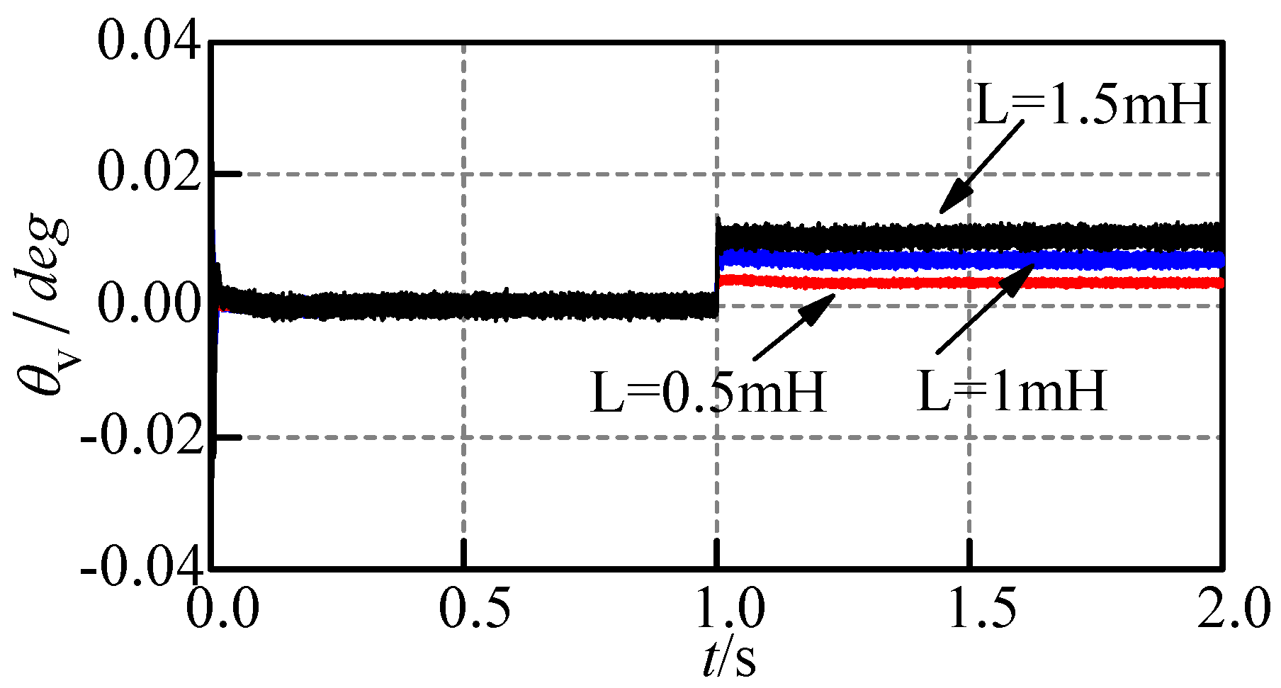
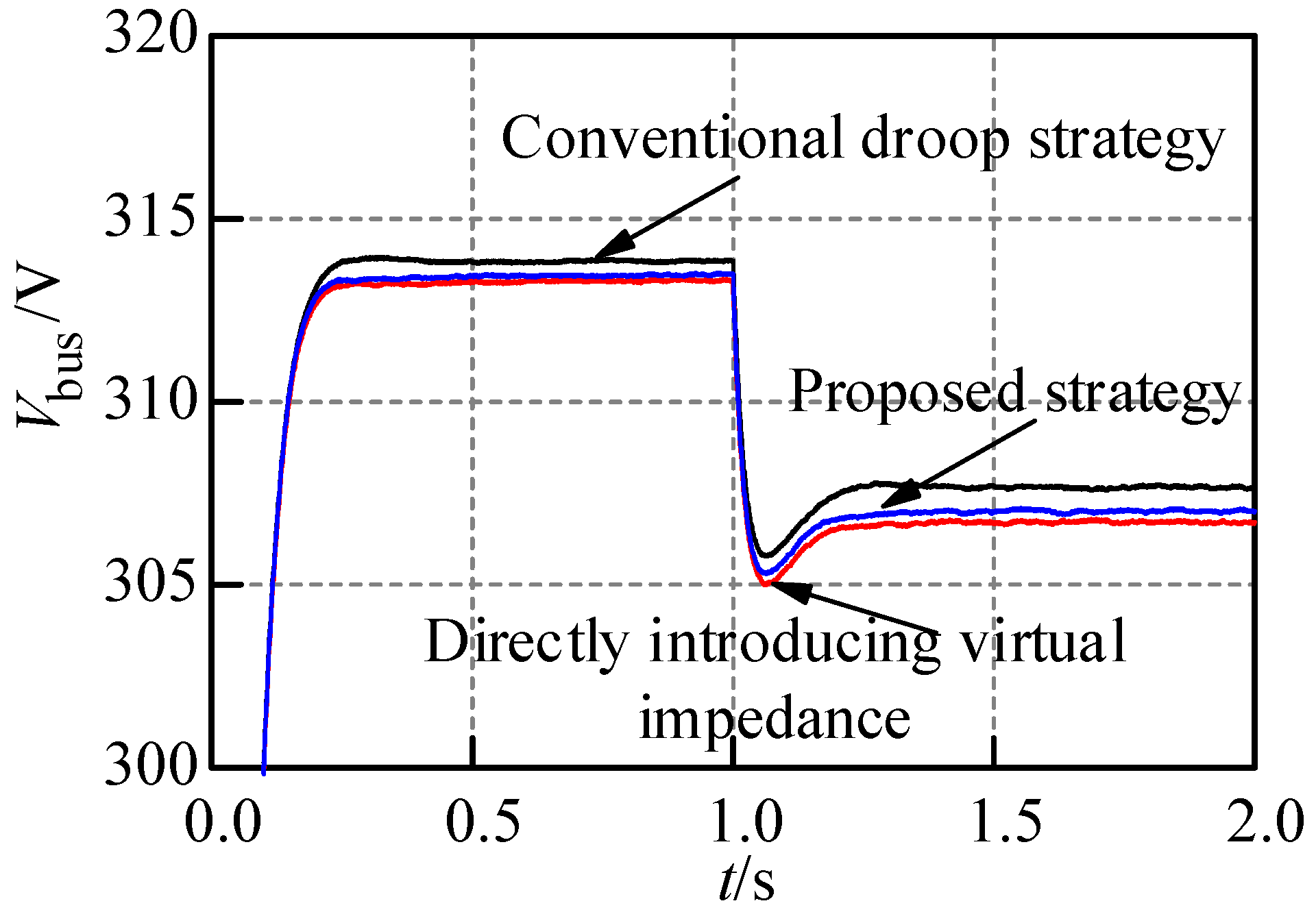
6. Simulation Results

The microgrid shown in Figure 11 was modelled in MATLAB R2014b/Simulink (MATLAB R2014b, MathWorks, Natick, MA, USA) to verify the effectiveness of the proposed control method. The microgrid contains four DGs and the line impedance between the DGs is set to resistive-inductive. The specific DG parameters, voltage and current double loop controller parameters, load parameters, and line impedance parameters are shown in Table 3.
The simulation was designed to verify the effectiveness of the proposed control strategy with respect to reactive power sharing and voltage control. Four inverters with rated capacities in the ratio of 1.5:3:4:4 were used in the simulation. Between 0 and 1 s of the simulation period, each system operates with a local load. After 1 s, the loads were added. Figure 12 shows the simulation results of the conventional droop control strategy and the control strategy based on consensus control of the reactive current. It can be found that between 1 and 2 s the active power is proportionally shared under both control strategies (as shown in Figure 12a,b). However, due to the mismatch of the line impedance, the reactive power sharing of the conventional droop control strategy is relatively poor (as shown in Figure 12c). In contrast, the proposed control strategy allows the equivalent output impedance of each micro-source to be effectively matched, thereby enabling the proportional sharing of reactive power in the ratio of 1.5:3:4:4 (as shown in Figure 12d). The system frequency will eventually converge and the frequency waveform obtained by the control strategy proposed in this paper is smoother (as shown in Figure 12e–f). In the simulation, the load switching is performed in 1 s. During the switching process, the virtual impedance will automatically change with the load distribution (as shown in Figure 12g–h). It can be seen, finally, that the virtual reactance dominates the system, which satisfies the P-f, Q-V droop control requirements.
To verify the effectiveness of introducing the virtual impedance compensation angle θv, the output power of the first inverter is taken as an example, as shown in Figure 13. Since the virtual impedance compensation angle eliminates the phase angle difference of the reference voltage, the power waveform is smoother and more stable compared with the situation when the compensation angle is not introduced.
The voltage sag at the microgrid AC bus is shown in Figure 14. As the conventional droop control is deviation-based, voltage sags may occur, especially when a virtual impedance is added. Compared with the control method based on direct introduction of virtual impedance, the bus voltage sag caused by the adaptive virtual impedance control method proposed in this paper is low.
A simulation was carried out to verify the reliability of the system under the reactive current consensus control strategy when communication failure occurs. In the simulation, the communication link between DGs 1 and 2 fails. Despite the failed communication link, the system is able to maintain the ratio of 1.5:3:4:4 in the sharing of reactive power while active power is controlled (as shown in Figure 15a,b). Therefore, when one communication link fails, the proposed control strategy still outperforms the conventional droop control method with regards to reactive power sharing. Even when communication fails, the adaptive virtual impedance based on reactive current consistency proposed in this paper still automatically changes with the load distribution during the load switching process (as shown in Figure 15c,d) and, ultimately, virtual reactance remains a dominant role in the system.

7. Conclusions

In this paper, reactive power sharing within an isolated microgrid using virtual impedance has been investigated.
The microgrid system adopts a distributed control structure without a central controller, in which each DG acts as an independent agent and adjacent DGs engage in one-way communication. The reactive power sharing is achieved through consensus control of the reactive current. In addition, the microgrid system proves to be asymptotically stable under this control strategy.
The virtual impedance correction term is obtained by the consensus control strategy of reactive current. Together with the static virtual impedance, the adaptive virtual impedance is introduced to eliminate the output impedance mismatch between adjacent micro-sources, thereby achieving proportional reactive power sharing without knowing specific line impedance parameters. Moreover, it has been proved that the proposed method can perform well even when a communication link fails.
The virtual impedance compensation angle θv is introduced to compensate for phase angle offset in the micro-source reference voltage caused by the introduction of virtual impedance, thus, the stability of the system can be enhanced. The power control loop is simplified without affecting the original droop characteristics, thereby reducing system complexity and limiting the voltage sag.

Author Contributions

The paper was a collaborative effort among the authors. Z.L. and Q.W. carried out relevant theoretical research, performed the simulation, analyzed the data, and wrote the paper. Y.Z., J.Z. and E.M. provided critical comments.

Acknowledgments

This work was supported by the National Science Foundation of China (61364027), the National Basic Research Program of China (973 Program, 2013CB228205), the National High-tech R and D Program of China (863 Program, 2015AA050204), and the Natural Science Foundation of Guangxi (2015GXNSFBA139235).

Conflicts of Interest

The authors declare no conflict of interest.

References

  1. Zhang, B.; Yan, X.; Li, D.; Zhang, X.; Han, J.; Xiao, X. Stable operation and small-signal analysis of multiple parallel dg inverters based on a virtual synchronous generator scheme. Energies 2018, 11, 203. [Google Scholar] [CrossRef]
  2. Chan, R.; Kwak, S. Improved finite-control-set model predictive control for cascaded h-bridge inverters. Energies 2018, 11, 355. [Google Scholar] [CrossRef]
  3. Li, B.; Zhou, L.; Sciubba, E. Power decoupling method based on the diagonal compensating matrix for vsg-controlled parallel inverters in the microgrid. Energies 2017, 10, 2159. [Google Scholar]
  4. Yoon, S.J.; Lai, N.B.; Kim, K.H.; Sciubba, E. A systematic controller design for a grid-connected inverter with lcl filter using a discrete-time integral state feedback control and state observer. Energies 2018, 11, 437. [Google Scholar] [CrossRef]
  5. Zhang, Y.; Liu, J.; Zheng, H.; Wei, H.; Liao, R. Study on Quantitative Correlations between the Ageing Condition of Transformer Cellulose Insulation and the Large Time Constant Obtained from the Extended Debye Model. Energies 2017, 10, 1842. [Google Scholar] [CrossRef]
  6. Liu, J.; Zheng, H.; Zhang, Y.; Wei, H.; Liao, R. Grey Relational Analysis for Insulation Condition Assessment of Power Transformers Based Upon Conventional Dielectric Response Measurement. Energies 2017, 10, 1526. [Google Scholar] [CrossRef]
  7. Hosseinzadeh, M.; Salmasi, F.R. Power management of an isolated hybrid AC/DC micro-grid with fuzzy control of battery banks. IET Renew. Power Gener. 2015, 9, 484–493. [Google Scholar] [CrossRef]
  8. Hosseinzadeh, M.; Salmasi, F.R. Robust optimal power management system for a hybrid AC/DC micro-grid. IEEE Trans. Sustain. Energy 2015, 6, 675–687. [Google Scholar] [CrossRef]
  9. Hosseinzadeh, M.; Salmasi, F.R. Fault-tolerant supervisory controller for a hybrid AC/DC micro-grid. IEEE Trans. Smart Grid 2018, 9, 2809–2823. [Google Scholar] [CrossRef]
  10. Yu, Z.; Ai, Q.; He, X.; Piao, L.; Sciubba, E. Adaptive droop control for microgrids based on the synergetic control of multi-agent systems. Energies 2017, 9, 1057. [Google Scholar] [CrossRef]
  11. Li, Z.; Zang, C.; Zeng, P.; Yu, H.; Li, H.; Li, S. Analysis of multi-agent-based adaptive droop-controlled ac microgrids with pscad. J. Power Electron. 2015, 15, 455–468. [Google Scholar] [CrossRef]
  12. Li, D.; Zhao, B.; Wu, Z.; Zhang, X.; Zhang, L. An improved droop control strategy for low-voltage microgrids based on distributed secondary power optimization control. Energies 2017, 10, 1347. [Google Scholar] [CrossRef]
  13. Sun, X.; Yang, Y.; Zhao, W.; Shen, H.; Tan, G. An adaptive droop control method for inverters in microgrid. Power Syst. Technol. 2014, 38, 2386–2391. [Google Scholar]
  14. Vasquez, J.C.; Guerrero, J.M.; Luna, A.; Rodriguez, P.; Teodorescu, R. Adaptive droop control applied to voltage-source inverters operating in grid-connected and islanded modes. IEEE Trans. Ind. Electron. 2009, 56, 4088–4096. [Google Scholar] [CrossRef]
  15. Chen, Y.; An, L.; Long, J.; Peng, Z.; Zhang, Q.; Zhipeng, L. Circulating current analysis and robust droop multiple loop control method for parallel inverters using resistive output impedance. Proc. CSEE 2013, 33, 18–29. [Google Scholar]
  16. W, Y.; An, L.; Jin, G. Improved robust droop multiple loop control for parallel inverters in microgrid. Trans. China Electrotech. Soc. 2015, 30, 116–123. [Google Scholar]
  17. He, J.; Li, Y.W.; Blaabjerg, F. An enhanced islanding microgrid reactive power, imbalance power, and harmonic power sharing scheme. IEEE Trans. Power Electron. 2015, 30, 3389–3401. [Google Scholar] [CrossRef]
  18. Lee, C.T.; Chu, C.C.; Cheng, P.T. A new droop control method for the autonomous operation of distributed energy resource interface converters. IEEE Trans. Power Electron. 2013, 28, 1980–1993. [Google Scholar] [CrossRef]
  19. He, J.; Li, Y.W. An enhanced microgrid load demand sharing strategy. IEEE Trans. Power Electron. 2012, 27, 3984–3995. [Google Scholar] [CrossRef]
  20. He, J.; Du, L.; Liang, B.; Li, Y.; Wang, C. Coupled-Virtual-Impedance Control for AC/DC Hybrid Microgrid Power Electronic Interlinking Unit with Dual Converters. IEEE Trans. Smart Grid 2018. [Google Scholar] [CrossRef]
  21. Dong, H.; Yuan, S.; Han, Z.; Cai, Z.; Jia, G.; Ge, Y. A Comprehensive Strategy for Accurate Reactive Power Distribution, Stability Improvement, and Harmonic Suppression of Multi-Inverter-Based Micro-Grid. Energies 2018, 11, 745. [Google Scholar] [CrossRef]
  22. Gupta, P.; Swarnkar, P. Intertied AC-DC Hybrid System Power Sharing Through Intelligent Droop Controller. Eng. Technol. Appl. Sci. Res. 2018, 8, 2609–2615. [Google Scholar]
  23. Yao, W.; Chen, M.; Matas, J.; Guerrero, J.M.; Qian, Z.M. Design and analysis of the droop control method for parallel inverters considering the impact of the complex impedance on the power sharing. IEEE Trans. Ind. Electron. 2011, 58, 576–588. [Google Scholar] [CrossRef]
  24. Guerrero, J.M.; Matas, J.; Vicuna, L.G.D.; Castilla, M.; Miret, J. Decentralized control for parallel operation of distributed generation inverters using resistive output impedance. IEEE Trans. Ind. Electron. 2007, 54, 994–1004. [Google Scholar] [CrossRef]
  25. Guerrero, J.M.; Vicuña, L.G.D.; Matas, J.; Miret, J.; Castilla, M. Output impedance design of parallel-connected UPS inverters with wireless load-sharing control. IEEE Trans. Ind. Electron. 2005, 52, 1126–1135. [Google Scholar] [CrossRef]
  26. Wang, C.; Xiao, Z.; Wang, S. Multiple feedback loop control scheme for inverters of the micro source in microgrids. Trans. China Electrotech. Soc. 2009, 24, 100–107. (In Chinese) [Google Scholar]
  27. Zhu, Y.; Zhuo, F.; Wang, F.; Liu, B.; Zhao, Y. A wireless load sharing strategy for islanded microgrid based on feeder current sensing. IEEE Trans. Power Electron. 2015, 30, 6706–6719. [Google Scholar] [CrossRef]
  28. He, J.; Li, Y.W. Analysis, design, and implementation of virtual impedance for power electronics interfaced distributed generation. IEEE Trans. Ind. Appl. 2011, 47, 2525–2538. [Google Scholar] [CrossRef]
  29. He, J.; Li, Y.W.; Guerrero, J.M.; Blaabjerg, F.; Vasquez, J.C. An islanding microgrid power sharing approach using enhanced virtual impedance control scheme. IEEE Trans. Power Electron. 2013, 28, 5272–5282. [Google Scholar] [CrossRef]
  30. Mahmood, H.; Michaelson, D.; Jiang, J. Accurate reactive power sharing in an islanded microgrid using adaptive virtual impedances. IEEE Trans. Power Electron. 2015, 30, 1605–1617. [Google Scholar] [CrossRef]
  31. Shafiee, Q.; Guerrero, J.M.; Vasquez, J.C. Distributed secondary control for islanded microgrids—A novel approach. IEEE Trans. Power Electron. 2014, 29, 1018–1031. [Google Scholar] [CrossRef]
  32. Micallef, A.; Apap, M.; Spiteri-Staines, C.; Guerrero, J.M.; Vasquez, J.C. Reactive power sharing and voltage harmonic distortion compensation of droop controlled single phase islanded microgrids. IEEE Trans. Smart Grid 2014, 5, 1149–1158. [Google Scholar] [CrossRef]
  33. Zhang, H.; Kim, S.; Sun, Q.; Zhou, J. Distributed adaptive virtual impedance control for accurate reactive power sharing based on consensus control in microgrids. IEEE Trans. Smart Grid 2017, 8, 1749–1761. [Google Scholar] [CrossRef]
  34. Qian, G.; Lin, L.; Hongyan, W.U.; Bai, Z.; Hao, M.A. Distributed power control strategy for microgrids considering adaptive virtual impedance. Autom. Electr. Power Syst. 2016, 40, 23–29. (In Chinese) [Google Scholar]
  35. Long, J.; Xing, H.; Wu, X. Research on improved microsource droop control method. Trans. China Electrotech. Soc. 2014, 29, 145–152. (In Chinese) [Google Scholar]
  36. De Brabandere, K.; Bolsens, B.; Van den Keybus, J.; Woyte, A.; Driesen, J.; Belmans, R. A voltage and frequency droop control method for parallel inverters. IEEE Trans. Power Electron. 2007, 22, 1107–1115. [Google Scholar] [CrossRef]
  37. Bidram, A.; Davoudi, A.; Lewis, F.L.; Qu, Z. Secondary control of microgrids based on distributed cooperative control of multi-agent systems. IET Gener. Transm. Dis. 2013, 7, 822–831. [Google Scholar] [CrossRef]
  38. Hosseinzadeh, M.; Yazdanpanah, M.J. Performance enhanced model reference adaptive control through switching non-quadratic Lyapunov functions. Syst. Control Lett. 2015, 76, 47–55. [Google Scholar] [CrossRef]
  39. El Boubakri, A. Analysis of the performance of droop controlled inverters in mini-grids. Electr. Comput. Eng. 2013, 82–150. [Google Scholar]
Figure 1. Equivalent circuit of a micro-source.
Energies 11 01801 g001
Figure 2. Bode diagram of the output impendence.
Energies 11 01801 g002
Figure 3. DG communication topology.
Energies 11 01801 g003
Figure 4. Virtual impendence realization scheme.
Energies 11 01801 g004
Figure 5. Equivalent circuit of DG.
Energies 11 01801 g005
Figure 6. Bode diagram of output impendence.
Energies 11 01801 g006
Figure 7. Virtual impendence angle.
Energies 11 01801 g007
Figure 8. The change of angle at different virtual impedances.
Energies 11 01801 g008
Figure 9. Voltage reference generator block.
Energies 11 01801 g009
Figure 10. Block diagram of the entire system control scheme.
Energies 11 01801 g010
Figure 11. Case study of the microgrid.
Energies 11 01801 g011
Figure 12. Performance comparison of the control strategy.
Energies 11 01801 g012aEnergies 11 01801 g012b
Figure 13. Comparison of power waveforms.
Energies 11 01801 g013
Figure 14. Microgrid AC bus voltage.
Energies 11 01801 g014
Figure 15. Performance of the proposed control strategy during a communication failure.
Energies 11 01801 g015
Table 1. Parameters of droop control.
Vdc/VL/mHC/μFKKvpKvi
8000.61500510100
Table 2. Parameters of the droop control.
LV/mHVdc/VL/mHC/μFKKvpKvi
0.88000.61500510100
Table 3. System parameters.
Parameter
Rated voltage220 V
No-load frequency50.5 Hz
Line impendencesZl1 0.8 mΩ, 4.3 mH
Zl2 0.6 mΩ, 4.3 mH
Zl3 0.5 mΩ, 3 mH
Zl4 0.4 mΩ, 2 mH
LoadLD1: 1.5 kW, 1.5 kVar
LD2: 3 kW, 3 kVar
LD3: 4 kW, 4 kVar
LD4: 4 kW, 4 kVar
LOAD5: 12.5 kW, 12.5 kVar
Control parameters
Droop coefficientm1/1.5 = m2/3 = m3/4 = m4/4 = 1 × 10⁻⁵
n1/1.5 = n2/3 = n3/4 = n4/4 = (2/3) × 10−4
kn1/1.5 = kn2/3 = kn3/4 = kn4/4 = 2/30
PI parameterDP = 0.01DI = 5
Coupling gain CIr7.5
Static virtual inductance0.5 × 10−3 H
Gain of adaptive virtual impedance kR = 1.5 × 10⁻⁴, kL = 0.02

