Article

Nanoscale Characteristics and Reactivity of Nascent Soot from n-Heptane/2,5-Dimethylfuran Inverse Diffusion Flames with/without Magnetic Fields

1
MIIT Key Laboratory of Thermal Control of Electronic Equipment, School of Energy and Power Engineering, Nanjing University of Science and Technology, Nanjing 210094, China
2
Advanced Combustion Laboratory, School of Energy and Power Engineering, Nanjing University of Science and Technology, Nanjing 210094, China
*
Author to whom correspondence should be addressed.
Energies 2018, 11(7), 1698; https://doi.org/10.3390/en11071698
Submission received: 8 May 2018 / Revised: 15 June 2018 / Accepted: 22 June 2018 / Published: 1 July 2018
(This article belongs to the Special Issue Nanotechnology for Energy Materials)

Abstract

:
In this study, the differences of nanostructure and oxidation reactivity of the nascent soot formed in n-heptane/2,5-dimethylfuran (DMF) inverse diffusion flames (IDF) with/without influence of magnetic fields were studied, and the effects of DMF-doped and magnetic fields were discussed. Morphology and nanostructures of the soot samples were investigated using high-resolution transmission electron spectroscopy and X-ray diffraction, and the oxidation reactivity characteristics were analyzed by thermogravimetric analyzer. Results demonstrated that both additions of DMF-doped and magnetic fields could promote soot production and modify the soot nanostructure and oxidation reactivity in IDF. Soot production increased along with the increase of DMF-doped. With DMF blends, more clustered soot particles and typical core-shell structures with well-organized fringes were exhibited compared with that formed from the pure n-heptane IDF. With effects of magnetic fields, the precursor formation and the oxidization of soot were promoted, soot production was enhanced. Soot particles became relatively more mature with typical core-shell structure, thicker shell, longer fringe lengths, smaller fringe tortuosity, higher graphitization degree and lower oxidation reactivity. With magnetic force pointed to the central line and the inner direction of IDF under the conditions of N pole and S pole of the magnet facing the flame, oxygen was trapped, having an increased residence time to get more chance to react with the fuel molecules to cause more soot to be yielded and oxidized. That resulted in the soot precursor promotion, soot production enhancement, and soot part-oxidization and graphitization.

1. Introduction

The soot particle is one important part of the common pollution emissions of combustion systems such as furnaces, internal combustion engines and gas turbine engines [1,2]. As suspended submicron particles, soot particles not only pollute the air [3] but harm the human respiratory system as well [4,5,6]. The formation and variation tendency are important for understanding the growth processes of soot particles. In recent years, more interests and attention of researchers have been focused on the studies of soot particles, especially on the formations and variation tendency of growth processes. The soot formation process has been studied widely [7,8,9,10,11,12,13]. It is universally accepted that the soot particles produced in hydrocarbon flames involve complex physical-chemical processes taking place by steps including fuel pyrolysis, polycyclic aromatic hydrocarbons (PAHs) formation, particle inception, sequential nucleation, coagulation, surface growth, carbonization, agglomeration and oxidation [7,8]. It is widely accepted that PAHs served as precursors of soot particles and surface growth species.
Researchers had conducted abundant research works on physical and chemical properties of soot produced in diffusion flames by using various techniques and methods. Due to the oxidizer surrounded by fuel in an inverse diffusion flame (IDF) and counter-flow flame, the formed soot was readily conveyed away from the main reaction region in the flame front by thermophoretic forces avoiding significant oxidation and carbonization by oxygen [14]. Therefore, IDF is widely utilized which is basically designed by exchanging oxidizer and fuel positions relative to a normal diffusion flame (NDF) configuration to obtain large samples of nascent soot particles. The differences of the soot characteristics between IDF and NDF were investigated. Mikofski et al. [15] compared the flame structure, PAHs, and soot zones between IDF and NDF using planar laser-induced fluorescence of hydroxyl radicals (OH PLIF), PAH PLIF and planar laser-induced incandescence of soot (soot PLII), respectively. Results indicated that soot appeared outside the flame front in IDF, and PAHs appeared outside the soot layer depending on the characteristic temperature. Blevins et al. concluded that particles emitted from IDF were similar to the soot precursors and appeared to be young soot on the verge of carbonizing [16]. Using a time-dependent, detailed-chemistry computational fluid dynamics (CFD) model, Katta et al. [17] had simulated an ethylene–air IDF. They found that all the PAHs species were produced outside the flame surface on the fuel side. Soot particles were reheated and cooled alternately while being entrained into and advected by the buoyancy-induced vortices. The large diameter and slight carbonization of soot particles could be observed in IDF. The temperature and soot volume fraction in IDF and NDF also have been experimentally measured [18,19]. Using laser diagnostics techniques and high-resolution transmission electron microscopy (HRTEM), the structure of precursor particles and their carbonization processes have been investigated experimentally to examine the early precursor soot in diluted ethene IDF [18]. Oh et al. [20] performed experimental measurements of flame structure and soot characteristics of diluted ethane IDF by changing the fuel dilution ratio and air/fuel ratio and found that soot inception and growth were weakly dependent on temperature as influenced by fuel dilution. Ying et al. [21,22] studied the nanostructure and oxidation reactivity of soot in ethylene IDF and NDF with butanol isomers and pentanol additions and compared the effects of the butanol isomers on the physical and chemical properties of soot. The effects of oxygen on soot production had been studied in recent years. Changing the Oxygen Index (OI) range from 21% to 37% in an ethylene IDF, Escudero et al. [23] found that the increasing OI enhanced soot volume fraction due to higher temperatures and soot formation rates. Jung et al. [24] enhanced the oxygen concentration in the oxidizer in IDF to result in the move of the beginning of the yellow flame, the increase of residence time and the higher degree of carbonization of young soot particles.
Due to the tightened fossil fuel resources and increasingly serious pollution emissions, biofuels were paid more attention to and arouse more interests from people. To reduce the dependence on traditional fossil fuels, the alternative biofuels were widely studied [25,26,27,28]. Various previous studies considering biofuel soot were conducted [29,30,31,32,33]. Chemical and morphological characterization of soot and soot precursors were studied with diesel surrogates, aromatic and aliphatic fuels [34,35,36,37,38]. It was found that diesel surrogate fuel produced five times more soot than the aliphatic hexane flame, and soot particle morphology became chain-like aggregates covered with liquid material with irregular boundaries. As an attractive potential biofuel, 2,5-dimethylfuran (DMF) offered high energy density and could be used to be the fuel alternative or additive. Recent years, more interests and attentions of researchers were focused on the development of DMF. There were amount of literatures focusing on the study of chemistry and flame structure of furanic fuel flames. Using molecular beam mass spectrometry and gas chromatography, the combustion chemistry and flame structure of furan group biofuels in flames of furanic compounds and those of other fuels have been investigated by Kohse-Höinghaus’s group [39,40]. They found that DMF offered a priori surprising ability to form soot precursors compared to less substituted furans and to other fuels [41,42]. The pyrolysis and oxidation of DMF had been studied and its tendency of soot formation had been analyzed [43]. Results revealed that soot was generated much higher compared to other oxygenated compounds. The effects of furans on soot particle formation in a counter-flow diffusion flames have been investigated using experimental and modeling methods [44]. Experimental results and modeling analysis showed that 2-methylfuran (MF) had a greater tendency to produce soot particles with respect to DMF because of more C4-species, benzene and PAHs by MF. Soot nanostructures and chemical functionalities generated in premixed flames of ethylene and ethylene doped with 20%DMF also have been investigated [45]. DMF is reported to decrease the soot particle emission [33,46,47]. Gogoi et al. [33] studied the sooting propensity, the oxidative reactivity and nanostructures of soot particles in a diesel diffusion flame with the addition of DMF (up to 15%) and found that soot emission reduced, and the oxidation reactivity of soot particles increased with increasing amount of DMF in the DMF/diesel blends. Liu et al. [48] developed a reduced toluene reference fuel (TRF) -DMF-PAH mechanism to predict the soot and NOx emissions for engines. These studies were conducted based on NDF, but there were few researches and literatures focusing on the effects of the addition of DMF on the oxidative reactivity and nanostructures of soot particles in IDF.
It had been known that the paramagnetic and/or diamagnetic fluids could be influenced by magnetic fields [49]. This suggested that the potential ability of magnetic control of air and fuel flows and the combustion process of flame [49,50,51,52,53,54]. Ueno [49] exposed the methane, propane and hydrogen flames to gradient magnetic fields of up to 2.2 T and 300 T/m strengths and found that flames bent to escape from magnet fields with high intensity. The effect of magnetic field gradients on partially premixed and diffusion flames were studied by Wakayama et al. [50,51,52]. Results indicated that combustion rate of flames increased with increasing magnetic field intensities. Baker et al. [54] applied a non-uniform upward decreasing magnetic field to a laminar jet diffusion flame. The experimental results showed that the flame height changed, visible soot inception occurred in the gradient of the magnetic induction. The influence of the gradient of the magnetic flux density on soot production in NDF also have been investigated [55,56]. Changing oxygen contents from 21% to 50%, the flame experienced different magnitudes ranging from 0 to 18.2 T2/m. Results showed that the modification of soot production in the flame depended mainly on the fields of oxygen mole fraction and temperature. The supplementary magnetic force acted mainly on oxygen due to its higher mass fraction and paramagnetic susceptibility.
The above reviews showed that magnetic fields had effects on combustion process by controlling the oxygen concentration field, and the modification of the soot formation tendency. However, there are very few detailed studies concerning nanostructure and oxidation characteristics of nascent soot generated in IDF with DMF addition under magnetic fields. Oxygen with relatively high paramagnetic susceptibility affected not only the combustion process of flame but also the evolution process of soot precursors. Furthermore, the soot formation and characteristics could be modified under the magnetic fields [55,56]. Therefore, the main goal of this study was to investigate effects of different addition amounts of DMF additive and magnetic fields on the nanostructure and oxidation reactivity of soot based on the n-heptane IDF. Combustion experiments on the nanostructure and oxidation reactivity of soot in n-heptane IDF with additions of DMF (up to 50%) were carried out. The internal structure of soot samples was examined using HRTEM and X-ray diffraction (XRD), the reactivity characteristics were extracted by thermogravimetric analyzer (TGA).

2. Experimental System and Analysis Methods

2.1. Experimental System

Combustion sampling system was mainly composed of an IDF burner, a fuel supply subsystem, a fuel evaporation subsystem, a heating subsystem, a magnetic field supply subsystem and a soot sampling subsystem as shown in Figure 1. The IDF burner consisted of three concentric stainless steel tubes including a 3.86 mm inner diameter (ID) center tube, a 15.30 mm ID intermediate tube, and a 32.36 mm ID outer tube. The intermediate and outer tubes were filled with perforated steel plates at the bottom to obtain uniform gas flows. Because of low velocity 9.3 cm/s and 3.1 cm/s, and Reynolds numbers 65 and 53 in the intermediate and outer tubes, respectively, the gas flows remain the laminar flow state. Oxidizer (air with high purity of 99.999%) was ejected from the central tube and surrounded by the fuel stream delivered in the coaxial intermediate tube, and nitrogen with high purity of 99.999% was ejected from the outer tube as protective gas. In the fuel supply system, n-heptane with purity of 99.95% was used as the base fuel. n-heptane had the similar molecular weight and the close boiling point to DMF. For n-heptane and DMF, the molecular weights were 100 and 96, the boiling points were 98.5 °C and 93.5 °C, respectively. Two fuels both were liquid fuel and fit to be blended, heated and evaporated. DMF with purity of 99.95% was used as the additive (up to 50%). The liquid-blended fuel was injected into a stainless steel evaporator controlled by heating bands at 150 °C. After being evaporated, the blended fuel gas was carried by a flow of N2 with high purity of 99.999% to the intermediate tube of the IDF burner maintaining the constant temperature of 150 °C in the pipeline by a heating system to prevent the condensation. C2H4 was used to be the ignition fuel for safety at the beginning stage of the liquid fuels to be injected into the evaporator. The gas flow rates were all controlled by high-performance digital mass flow controllers.
Soot samples were collected above the burner surface by quartz plates with a diameter of 100 mm and a thickness of 6 mm. The sampling height was 27 mm for each flame. This deposition method was used in the previous studies [57,58,59]. Quartz plate was cooled by an aluminum cool dish at its top surface. The cool dish with a thickness of 14 mm had its own water circulating. Soot particles were driven thermophoretically to the cold wall of the quartz plate to be condensed and captured on the surface of the quartz plate ultimately. The sampling time was kept constant at 10 min, and the sampled soot was scraped, crushed into powder and stored for subsequent analysis. To guarantee enough soot obtained, the soot sampling experiments were repeated several times in the same case.
Magnetic fields were supplied by a strong magnetic Nd-Fe-B permanent magnet (50 mm × 50 mm × 35 mm). Nd-Fe-B magnet was located at the top of the aluminum cool dish which cannot be magnetized. Without magnet represents the cases of without effects of magnetic fields, N pole and S pole represent the cases of N pole and S pole of the magnet facing the flame, respectively. Magnetic fields intensity of Nd-Fe-B magnet used in this study were measured by a high-precision gauss meter. The magnetic field intensity in each measurement point was monitored for five times, the average value was obtained. The measurement points and the distribution of magnetic field intensity were shown in Figure 2. The magnetic field could change the flow rate, the mixing of the flame compounds, flame height and lift-off height, maximum temperature, soot inception occurred, and so on. These effects are attributed to the magnetic force, which develops on air via its action on the paramagnetic oxygen molecules [55,56,60,61,62,63]. Oxygen exhibits a relatively high paramagnetic susceptibility. It is known that the single magnet offered the non-uniform magnetic field. The gradient of the magnetic field increased from the center point 1 to the edge positions of the magnet as point 2/3/4/5 as shown in Figure 2a and decreased away from the surface of the magnet. Therefore, no matter in case of N pole or S pole, oxygen molecules has the net magnetic force F = Foutside − Finside facing the central line and the inner direction of the flame as shown in Figure 2d.
The detailed experimental conditions for IDF used in this study were summarized in Table 1. The basic condition was pure n-heptane IDF without effects of magnetic fields. Basic fuel n-heptane doped with 25% and 50% DMF addition of mole fraction with/without effects of magnetic fields. Flow rates of liquid fuel were determined to keep fuel gas mixture rates constant for all cases, and the fuel gas mixture is form the complete evaporation of mixed liquid fuels. The flow rates of air, carrier N2 and protector N2 remained the appropriate values to obtain a basic IDF and unchanged.

2.2. Analysis Methods

Soot morphology and nanostructure, and thermogravimetric analysis were implemented by using the following analysis methods to find out the compact relationship between common soot structural features and oxidation reactivity.
The internal structural characteristics of sampled soot were observed by a FEI Titan G2 60–300 transmission electron microscope (Field Emission Inc., Hillsboro, ND, USA) operated at an accelerating voltage of 300 kV with 0.09 nm point resolution corrected by a spherical aberration corrector under the objective lens. The images with 1024–1024 pixels were obtained by a Gatan Digital Micrograph using a Gatan Orius SC 1000B CCD camera (Gatan Inc., Pleasanton, CA, USA) with the exposure time of 0.5–1.0 s. For all test samples, the images were acquired from more than four widely separated locations, and at least twenty images were obtained.
Soot nanostructure features, including fringe length and tortuosity, were estimated through quantification of the HRTEM images which were processed by the customized analysis algorithms. The image processing method, consisting of digital image processing and fringe characterization, was similar to the one developed by Maria and Yehliu et al. [64,65,66,67]. The image processing run in MATLAB (2014) software with customized algorithms including several operations, such as negative transformation, region of interest selection, contrast enhancement, Gaussian lowpass filter, top-hat transformation, thresholding to obtain a binary image, morphological modification, skeletonization, and short fringes and boundary fringes removal. The fringe characterization generated statistics on fringe length and tortuosity based on the skeletons of the graphene lamellae [21].
In the HRTEM images, a measure of the physical extent of the atomic carbon layer planes was presented as fringe length, and a value of curvature of the fringes arising from odd numbered five- and seven-membered ring structures was signed as fringe tortuosity [64,65,66,67,68,69]. It was reported that the fringe length and tortuosity obtained from HRTEM images could change with a long exposure time of the electron beam irradiation [70]. Here this effect of the electron beam was ignored due to the short exposure time. Histograms were created from the acquired data of fringe length and fringe tortuosity. In this study, fringe lengths shorter than 0.5 nm which was about the size of two fused aromatic rings were removed. The largest standard deviations of the fringe length and fringe tortuosity for all the processed images were 0.03 nm and 0.02, respectively.
The crystallite parameters and the graphite degree of soot particles were characterized by X-ray diffractometer, and the test instrument was D8 Advance X-ray diffraction instrument (Bruker, Karlsruhe, Germany) with Cu Kα radiation (1.5418 Å, 45 kV, 25 mA). The instrument with scan range of 10–110° was used at scan step size of 0.02°and scan speed of 0.2 s/step [22,64].
The d002 value of the carbon crystallite can be obtained by the Debye-Scherrer formula [70,71].
d 002 = λ 2 s i n θ 002
where λ represents emission wavelength (0.15406 nm), θ002 represents the diffraction angle matched for C(002), d002 represents the separation distance of C(002).
The graphitization degree of can be calculated by the Merlin formula [71,72].
g = 0.3440 d 002 0.3440 0.3354 × 100 %
where g represents the primary soot particles graphitization degree, 0.3440 (nm) represents the layer separation distance of fully non-graphite crystals, 0.3354 (nm) represents the layer separation distance of the ideal graphite crystals.
The oxidation reactivity of soot was evaluated by an STA 449 F3 Jupiter thermogravimetric analyzer (Netzsch, Selb, Germany). Under conditions of a constant temperature of 500 °C and the atmospheric pressure, the oxidation reactivity of soot was examined through the isothermal oxidation. The soot samples were heated up in the protective gas flow of Ar (100 cc/min) from 50 °C to 300 °C, and then the temperature was kept constant for one hour to remove volatile organic fraction (VOF). After that, the soot samples continued to be heated up from 300 °C to 500 °C. Once reaching 500 °C, an oxygen mixture flow (78% Ar and 22% O2) at a constant flow rate of 100 cc/min was used to replace the initial Ar flow. Subsequently, the isothermal oxidation process began and lasted for 150 min. The sample remainders were weighed after the isothermal oxidation tests, and the mass loss of each sample was normalized. The test uncertainty was ±5% error which derived from a set of isothermal oxidation experiments. Two separate experiments were carried out to verify the reproducibility of the TGA results [21,22,64].

3. Results and Discussion

3.1. Soot Production from n-Heptane/DMF IDF with/without Magnetic Fields

While using the deposition method to collect soot samples, the quality of soot samples colleting time for 10 min were weighed by a precision balance in each case. To obtain considerable quality of soot for subsequent analysis, the soot collection times in each case were more than six times. The average values of soot production were obtained and shown in Figure 3. The case of without magnetic fields was designated as of without magnet. If the flame and soot production were affected by the magnetic fields, there existed two cases. N pole represented the case of N pole of the magnet facing the flame. Accordingly, S pole represented the case of S pole of the magnet facing the flame.
Figure 3 revealed that pure n-heptane IDF generated very low levels of soot production, approximately 9 mg/10 min, due to the higher smoke point of n-heptane. Soot production increased with the addition of DMF in n-heptane IDF. Because of higher productions of soot precursors including acrolein, methyl vinyl ketone, furfural, and phenol C4-species, benzene and PAHs from furanic fuels [39,40,41], especially for DMF [41], soot was generated much more compared to other oxygenated compounds.
In Figure 3, magnetic fields could slightly enhance the soot production. The enhancement of S pole facing the flame on soot formation was a little larger than that of N pole. It has been reported that the oxygen paramagnetic force could change the transmission characteristics of the main combustion reaction components, such as OH radical concentration, NOx concentration, and soot precursors, to modify the combustion efficiency, emissions and soot particle formations [60,61,62,63]. Thus, oxygen with relatively high paramagnetic susceptibility was closely related to the soot production. No matter in cases of S pole or N pole, the oxygen paramagnetic forces showed the direction heading the central line and the inner direction of IDF as shown in Figure 2d. More oxygen would be forced to appear at the lower locations of the flame and trapped to have an increase in the residence time [55,56]. This leaded to longer trip for oxygen having more chance reacting with the fuel molecules. When fuel molecules were increasingly exposed to oxygen, the chances of soot precursor and soot oxidation were higher. So the soot precursors might be promoted. Due to the unique configuration of the oxidizer surrounded by fuel in IDF, the soot precursors readily aggregate and grow to be the nascent soot particles avoiding significant oxidation and carbonization by oxygen. Therefore, the soot production could be enhanced.
The analysis above could be summarized to say that soot production increased with more additions of DMF and were the lowest level from pure n-heptane IDF. Soot production was promoted by effects of magnetic fields. No matter in N pole case or in S pole case, more soot was formed, and the soot production was enhanced. Results indicated that effects of magnetic fields in the case of S pole of the magnet facing the flame on the soot promotion and the soot production was a little stronger than that in the case of N pole.

3.2. Soot Morphology Analysis by TEM

The soot samples from pure n-heptane IDF and doped DMF IDF were analyzed by TEM. For all cases, more than three TEM images were obtained from widely separated locations on soot sample, and the representative morphology images of soot were illustrated in Figure 4. All TEM images with lower magnification revealed that dozens or hundreds of the soot particles clustered in chains, branched or tufted forms.
Without magnetic fields, as shown in Figure 4O1–O3, the diameters of soot from pure n-heptane IDF in O1 were smaller compared with that from IDF in O2 with 25% DMF-doped and in O3 with 50% DMF-doped. From pure n-heptane IDF, the younger soot was sampled, but less soot production was collected. The diameters of the soot, which was similar to single granular particles on the peripheral location of the branched or tufted forms, were compared. It is interesting that the younger soot with the smaller diameter was tufted as transparent liquid-like sticky material forms in O1. Due to n-heptane with higher smoke point, on the same sample height, less PAHs which were considered as the precursor of soot particles was produced by condensation polymerization [73,74]. With DMF-doped, an abundance of PAHs was generated, and the additions of oxygenated hydrocarbons occurred. It promoted the surface growth of soot with the increasing of DMF-doped. The diameters of soot particles in O3 were slightly larger than that in O2, and significant larger than that in O1. The soot particles presented as the liquid-like material with sticky characters and irregular shapes which evolved from a chemical condensation of heavy PAHs. It could be seen that the liquid-like soot particles presented partially fusing into each other without clear boundaries, was difficult to distinguish individual particles. This phenomenon in O3 was more prominent than that in O2.
Under magnetic fields, in the cases of N pole or S pole of magnet facing the flame, the soot diameters in N1–N3 and S1–S3 appeared the similar phenomenon in terms of morphology features in O1–O3. With additions of DMF-doped in N2, N3 and S2, S3, the more soot production generated in comparison to the lower amount of soot generated from pure n-heptane IDF in N1 and S1. With the effects of magnetic fields, the diameters of soot particles became slightly larger in the comparison cases with the same components of fuels, such as N1 and S1, N2 and S2, N3 and S3, compared with that in O1, O2, O3, respectively. In N2, N3 and S2, S3, it also could be seen the soot particles presented the lower amount of film-like materials embedded with each other than that from the pure n-heptane IDF in N1 and S1. The soot formed under magnetic fields conditions showed lightly characters of liquid-like material with sticky. It aggregated with irregular over-layers and shaped closely to the sphere granule. That meant that the soot particles were partly oxidized and graphitized. This phenomenon in cases as N1–N3 appeared stronger than that in cases as S1–S3. As for analysis of soot production, because the magnetic forces on oxygen pointed to the central line and the inner direction of IDF, oxygen was driven to have an increase in the residence time which caused more soot to be yielded and oxidized in cases of N1–N3 and S1–S3. By the extra effects of oxygen under magnetic fields, the evolution of soot was promoted, and the chances of soot oxidation were higher. Thereupon, more soot particles with part graphitization were produced.
It could be concluded that, the soot collected from pure n-heptane IDF with the smaller diameter was younger, and it tufted as transparent liquid-like sticky material forms. With more DMF addition, the diameters of soot particles became slightly larger. With effects of magnetic fields, the soot presented the lower amount of shallow film-like materials, and it aggregated as approximate spherical particles in the form of chain-like, branched or tufted forms due to part oxidization and graphitization. The magnet with N pole facing the flame offered a little stronger effect on the soot aggregation than that of S pole facing the flame.

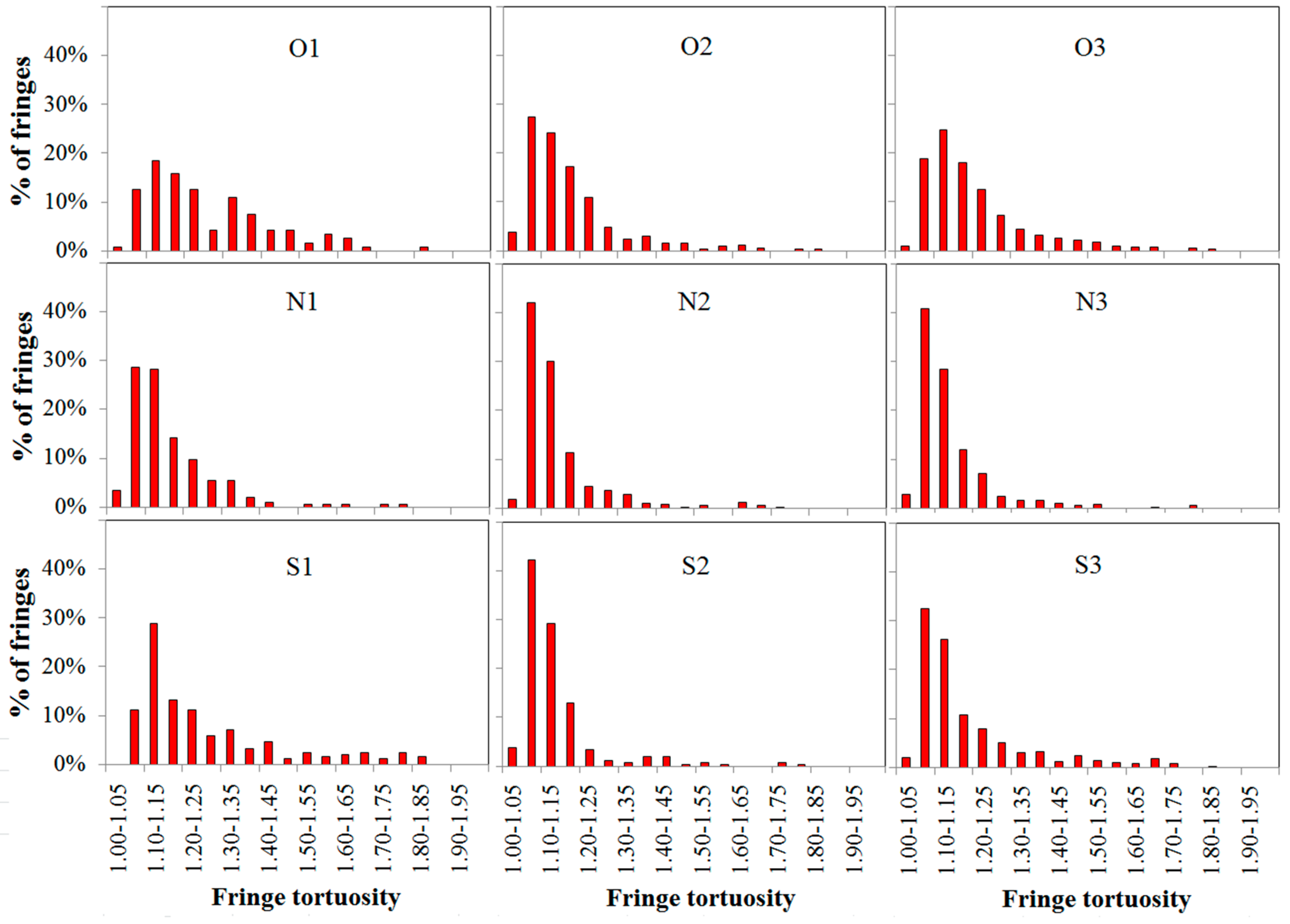
3.3. Soot Nanostructure Analysis by HRTEM and Fringe Analysis

To have better understanding the soot structural characteristics, HRTEM images of soot particles with higher magnification were acquired. In each case, three HRTEM images were processed and the nanostructure features were analyzed, and the representative HRTEM images were shown in Figure 5. It could be seen the soot aggregated with irregular shaped over-layers. Most of soot particles had the core-shell structure. The core area was filled with amorphous structures which had very little or no crystallinity with relatively strong oxidation activity. The core was surrounded by the orderly bordered lamellae as the fullerenic nanostructure which was similar to the fingerprint structure and partly carbonized yet [75,76,77,78]. It could be noted that the oxidation activity of soot depended on comprehensive consideration of the area size of the soot particle core and the thickness of the shell around.
In Figure 5 O1–O3, it showed the HRTEM images of soot from different fuel components under conditions without magnetic fields. As shown in O1, the soot sampled in pure n-heptane IDF showed relatively the smaller diameter and the thinner over-layers which presented as film-like materials in the lower magnification TEM images. Soot particles presented as amorphous structures with the short and disordered lamellae which owned relatively messy fringes with very little or no crystallinity. With DMF-doped in O2 and O3, the typical core-shell structure as the fullerenic lamellae could be found out in soot HRTEM images. Case of O2 with 25% DMF-doped showed more typical core-shell structure than that in O3 with 50% DMF-doped. The soot particles were comprised by partially or completely closed shells with different diameters and diverse degrees of curvature. The central areas of the shells were filled with the amorphous carbon which had high oxidation activity.
With effects of magnetic fields, in HRTEM images of Figure 5 N1–N3 and S1–S3, the soot appeared close resemblance to the tendency of the lamellae structures in O1–O3. With DMF-doped in N2, N3 and S2, S3, the core-shell structures were readily more evident than that in N1 and S1. The soot particles sampled from pure n-heptane IDF in N1, S1 under magnetic fields were comprised by more prevalent smaller core-shell structures. Nevertheless, the soot had the amorphous structures in O1 without effects of magnetic fields. This meant that the soot became more mature due to effects of magnetic fields in pure n-heptane IDF. The similar formers of soot nanostructures were performed in DMF-doped cases under magnetic fields. In these cases, N2 and S2 with 25% DMF-doped performed more mature soot than that of N3 and S3 with 50% DMF-doped. Due to the lower smoke point and easier soot formation of DMF, the IDF with the synergistic effects of two fuels could generate relatively more soot precursors at the same sample height. As aforementioned analysis, oxygen with relatively high paramagnetic susceptibility could play an important role in the formation of soot precursors. Through modification of oxygen, magnetic fields not only promoted the generation process of soot precursors, but also affected on the end stage of soot evolution process and produced more part-oxidized and graphitized soot particles. It suggested that magnetic fields could offer considerable effects on the younger soot through the evolution process of PAHs, oxygenated hydrocarbons and the surface growth to produce more soot particles with part-oxidization and graphitization.
The regions of interest in the single layers of soot of three HRTEM images were studied by the HRTEM image analysis algorithms, and the results presented representative skeletonized fringes in these regions in Figure 6. The short and disordered fringes in amorphous structures were shown in O1, and the short fringes with the relatively higher degree of curvature in the small size core-shell structures were shown in N1 and S1 from the pure n-heptane IDF under magnetic fields. Longer and well-organized fringes in the typical core-shell structure were observed in O2 and O3, N2 and N3, S2 and S3. It should be noted that these cases of O2, N2, S2 with 25% DMF-doped showed more evidently typical core-shell structure than that of O3, N3, S3 with 50% DMF-doped. This indicated that soot particles became more mature with 25% DMF-doped than that 50% DMF-doped. Under magnetic fields, not only the relatively longer and ordered fringes, but also the thicker shell of soot particles presented in N1 and S1, N2 and S2, N3 and S3 compared with that in O1, O2, O3 without effects of magnetic fields, respectively. It suggested that soot particles were promoted to become more mature with effects of magnetic fields. These results shown in Figure 6 were good agreements with the analysis in TEM images and HRTEM image.
Fringe length and fringe tortuosity histograms which were calculated from the skeletonized fringes by the HRTEM image analysis algorithms were shown in Figure 7 and Figure 8, respectively. In these histograms, fringes mainly concentrated on the short side nearby fringe length of 0.6–0.7 nm and fringe tortuosity of 1.10–1.15 in O1, N1 and S1. With DMF additions, the fringe length distribution concentrated to the approximate range of 0.7–0.8 and the fringe tortuosity distribution concentrated to the approximate range of 1.05–1.10. It showed that the distribution concentration in fringe tortuosity histograms under magnetic fields moved obviously to the lower area in comparison to that without magnetic fields. This meant that the soot sampled under magnetic fields had the smaller fringe tortuosity.
The mean values of the fringe length and the fringe tortuosity were summarized in Table 2. Because of the younger soot particles with amorphous structures from pure n-heptane IDF, the soot fringes offered the relatively smaller mean fringe length of and the larger mean fringe tortuosity in O1, N1 and S1. With 25% DMF-doped, the mean fringe lengths changed larger and the mean fringe tortuosity switched smaller due to more mature soot particles with well-organized core-shell structure in O2, N2 and S2. With addition of DMF-doped up to 50%, the mean fringe lengths reduced, and the mean fringe tortuosity increased in O3, N3 and S3. Under conditions of magnetic fields, the soot fringes from pure n-heptane IDF showed the larger mean fringe lengths and the smaller mean fringe tortuosity in N1 and S1 compared with that without influence of magnetic fields in O1. The same trends in the fringe characters of the soot from IDF with effects of magnetic fields also were presented in N2, S2 and N3, S3. As before-mentioned, the evolution process of soot was promoted by oxygen with relatively high paramagnetic susceptibility affected by magnetic fields, and the soot was more seriously oxidized and became more mature. These promotions from the influences of magnetic fields in N1–N3 were a little stronger than that in S1–S3.
Soot nanostructure analysis studied by the HRTEM image could be summarized that, typical core-shell structures were observed in soot particles with DMF-doped, and the soot became more mature with effects of magnetic fields. It might be that the younger soot evolution process of PAHs, oxygenated hydrocarbons and the soot surface growth were promoted, more soot particles were part-oxidized and graphitized. Furthermore, the magnet with N pole facing the flame offered a little stronger effect on the promotions of the soot evolution process than that with S pole facing the flame. The skeletonized fringes were extracted by the HRTEM image analysis algorithms. The fringe length and the fringe tortuosity were consistent with analysis in TEM images and HRTEM image.

3.4. Soot Graphitization Analysis

To further ascertain the carbonization of the soot, XRD spectra had been implemented and the results illustrated in Figure 9 and listed in Table 3. The C(002) band (2θ002 ≈ 25°), which represented the character of crystalline graphitic carbon, could be used to evaluate the graphitization degree of soot particles. Graphitization degree marked as g could be calculated out by Equations (1) and (2) according to the data of the peak diffraction angle θ002. Results of θ002, the separation distances d002 and the graphitization degrees g of soot particles are shown in Table 3 for each case.
In Figure 9 and Table 3, with additions of 25% DMF-doped in O2, N2 and S2, θ002 were closer to the diffraction angle of 25° compared with the cases with additions of 50% DMF-doped in O3, N3 and S3, respectively. In O1, N1, S1 with pure n-heptane, θ002 were the smallest in each group of compassion cases. It indicated that the soot particles presented higher graphitization degrees due to the little larger θ002. It was verified that the soot with 25% DMF-doped showed highest graphitization degree with/without effects of magnetic fields, and the case of pure n-heptane had the lowest graphitization degree. With effects of magnetic fields, the diffraction peaks of soot shifted to right slightly. It changed a little larger leading to higher graphitization degree in N1, S1 relative to that in O1. The similar tendency could also be observed in N2, S2 and N3, S3 in comparison with O2, O3, respectively. Comparing the cases of N pole and S pole, it could be found out that the soot particles presented a little larger peak diffraction angles and slightly higher graphitization degrees with N pole of magnet facing the flame.
Therefore, with DMF-doped or with effects of magnetic fields, the peak diffraction angles of soot changed larger and presented higher graphitization degrees. The results showed good agreements with the analysis above of nanostructures and fringe parameters in TEM images and HRTEM images.

3.5. Oxidation Reactivity of the Soot

The oxidation process could be reflected in the TG curves. To compare the oxidation reactivity among different samples with different initial mass, the thermogravimetric curve of each sample was normalized. The normalized mass traces during the isothermal oxidation tests by TG were shown in Figure 10 and Figure 11.
As could be seen in Figure 10a–c, the soot particles from pure n-heptane IDF all presented highest soot oxidation reactivity due to a mass of amorphous carbon. With additions of DMF-doped, the oxidation reactivity of soot decreased because the soot particles had been part oxidized and graphitized to become more mature. The soot particles in the cases with 25% DMF-doped offered lower oxidation reactivity than that with 50% DMF-doped. It indicated that oxidation reactivity of soot particles depended on the amount of additions of DMF-doped.
In comparison with oxidation reactivity of soot without influence of magnetic fields, the soot particles had slightly lower oxidation reactivity with effects of magnetic fields in Figure 11a–c. Under magnetic fields, the similar trends were shown in all cases in Figure 11, regardless of N pole or S pole of magnet facing the flame. It also could be observed that the soot particles collected from the cases of N pole facing the flame had lower oxidation reactivity than that of S pole cases. It was consistent with the results shown in analysis of nanostructures and fringe parameters in TEM images and HRTEM image and graphitization degrees by XRD.

4. Conclusions

In this study, a comparison of research on the nanostructure and oxidation reactivity of soot generated in n-heptane/DMF IDF with/without the influences of magnetic fields was conducted. The main soot characterization results and effects of DMF-doped and magnetic fields obtained from the present study were summarized as follows:
(1)
Dozens or hundreds of the soot particles clustered in chains, branched or tufted forms. The younger soot tufted as transparent liquid-like sticky material forms with a mass of amorphous structures and high oxidation reactivity from pure n-heptane IDF without magnetic fields.
(2)
With additions of DMF-doped, the soot production increased obviously. Soot particles with sticky characters and irregular shapes presented as over-layers or liquid-like materials embedded with each other. The core-shell structures of soot particles with well-organized fringes were exhibited. The diameters of soot particles increased, mean fringe lengths changed larger and mean fringe tortuosity switched smaller, the soot presented lager peak diffraction angles, higher graphitization degrees, and lower oxidation reactivity.
(3)
With effects of magnetic fields, no matter in N pole case or in S pole case, the soot precursors were promoted, and the soot production was enhanced. The enhancements of soot production in cases of S pole facing the flame were a little larger than that of N pole. Soot particles aggregated as approximate spherical particles with irregular shaped over-layers.
(4)
Under magnetic fields, the soot presented as a typical core-shell structure, thicker shell, longer fringe lengths, smaller fringe tortuosity, higher graphitization degree and lower oxidation reactivity. Oxygen was trapped to have an increased residence time to lead more soot to be yielded and oxidized. Soot particles were part oxidized and graphitized. They became relatively a little more mature in the cases of the N pole facing the flame than that of S pole cases.

Author Contributions

B.J. performed the experiments, analyzed the data and wrote the paper; P.W. performed the experiments, analyzed the data; Y.Y. and M.L. discussed; D.L. supervised the work and revised the paper.

Funding

This work was supported by the National Natural Science Foundation of China (51706103, 51776181, 51576100); the National Key Research and Development Program of China (2018YFB0605200); 333 Program of Jiangsu Province (BRA2017428); the Jiangsu Provincial Innovative Project of Graduate Education (KYZZ16_0184); and the Jiangsu Provincial Project of “Six Talent Summit” (2014-XNY-002).

Conflicts of Interest

The authors declare no conflict of interest.

References

  1. Hayne, B.S.; Wagner, H.G. Soot formation. Prog. Energy Combust. Sci. 1981, 7, 229–273. [Google Scholar] [CrossRef]
  2. McEnally, C.S.; Pfefferle, L.D.; Atakan, B.; Kohse-Höinghaus, K. Studies of aromatic hydrocarbon formation mechanisms in flames: Progress towards closing the fuel gap. Prog. Energy Combust. 2006, 32, 247–294. [Google Scholar] [CrossRef]
  3. The Worldwatch Institute. State of the World into a Warming World; The Worldwatch Institute: Washington, DC, USA, 2009. [Google Scholar]
  4. Barfknecht, T.R. Toxicology of soot. Prog. Energy Combust. Sci. 1983, 9, 199–237. [Google Scholar] [CrossRef]
  5. Donaldson, K.; Li, X.Y.; MacNee, W. Ultrafine (nanometre) particle mediated lung injury. J. Aerosol Sci. 1998, 29, 553–560. [Google Scholar] [CrossRef]
  6. Neumann, H.-G. Health risk of combustion products: Toxicological considerations. Chemosphere 2001, 42, 473–479. [Google Scholar] [CrossRef]
  7. Glassman, I. Soot formation in combustion processes. Symp. Int. Combust. 1988, 22, 295–311. [Google Scholar] [CrossRef]
  8. Dobbins, R.A.; Fletcher, R.A.; Chang, H.-C. The evolution of soot precursor particles in a diffusion flame. Combust. Flame 1998, 115, 285–598. [Google Scholar] [CrossRef]
  9. Kennedy, I.M. Models of soot formation and oxidation. Prog. Energy Combust. Sci. 1997, 23, 95–132. [Google Scholar] [CrossRef]
  10. Richter, H.; Howard, J.B. Formation of polycyclic aromatic hydrocarbons and their growth to soot—A review of chemical reaction pathways. Prog. Energy Combust. Sci. 2000, 26, 565–608. [Google Scholar] [CrossRef]
  11. Stanmore, B.R.; Brilhac, J.F.; Gilot, P. The oxidation of soot: A review of experiments, mechanisms and models. Carbon 2001, 39, 2247–2268. [Google Scholar] [CrossRef]
  12. Wang, H. Formation of nascent soot and other condensed-phase materials in flames. Proc. Combust. Inst. 2011, 33, 41–67. [Google Scholar] [CrossRef]
  13. Camacho, J.; Lieb, S.; Wang, H. Evolution of size distribution of nascent soot in n- and i-butanol flames. Proc. Combust. Inst. 2013, 34, 1853–1860. [Google Scholar] [CrossRef]
  14. Kang, K.T.; Hwnag, J.Y.; Chung, S.H.; Lee, W. Soot zone structure and sooting limit in diffusion flames: Comparison of counterflow and co-flow flames. Combust. Flame 1997, 109, 266–281. [Google Scholar] [CrossRef]
  15. Mikofski, M.A.; Williams, T.C.; Shaddix, C.R.; Fernandez-Pello, A.C.; Blevins, L.G. Structure of laminar sooting inverse diffusion flames. Combust. Flame 2007, 149, 463–478. [Google Scholar] [CrossRef] [Green Version]
  16. Blevins, L.G.; Fletcher, R.A.; Benner, J.B.; Steel, E.B.; Mulholland, G.W. The existence of young soot in the exhaust of inverse diffusion flames. Proc. Combust. Inst. 2002, 29, 2325–2333. [Google Scholar] [CrossRef]
  17. Katta, V.R.; Blevins, L.G.; Roquemore, W.M. Dynamics of an inverse diffusion flame and its role in polycyclic-aromatic-hydrocarbon and soot formation. Combust. Flame 2005, 142, 33–51. [Google Scholar] [CrossRef]
  18. Lee, E.J.; Oh, K.C.; Shin, H.D. Soot formation in inverse diffusion flames of diluted ethane. Fuel 2005, 84, 543–550. [Google Scholar] [CrossRef]
  19. Makel, D.B.; Kennedy, I.M. Soot formation in laminar inverse diffusion flames. Combust. Sci. Technol. 1994, 97, 303–314. [Google Scholar] [CrossRef]
  20. Oh, K.C.; Lee, U.D.; Shin, H.D.; Lee, E.J. The evolution of incipient soot particles in an inverse diffusion flame of ethene. Combust. Flame 2005, 140, 249–254. [Google Scholar] [CrossRef]
  21. Ying, Y.; Liu, D. Effects of butanol isomers additions on soot nanostructure and reactivity in normal and inverse ethylene diffusion flames. Fuel 2017, 205, 109–129. [Google Scholar] [CrossRef]
  22. Ying, Y.; Xu, C.; Liu, D.; Jiang, B.; Wang, P.; Wang, W. Nanostructure and oxidation reactivity of nascent soot particles in ethylene/pentanol flames. Energies 2017, 10, 122. [Google Scholar] [CrossRef]
  23. Escudero, F.; Fuentes, A.; Demarco, R.; Consalvi, J.-L.; Liu, F.; Elicer-Cortés, J.C.; Fernandez-Pelloe, C. Effects of oxygen index on soot production and temperature in an ethylene inverse diffusion flame. Exp. Therm. Fluid Sci. 2016, 73, 101–108. [Google Scholar] [CrossRef] [Green Version]
  24. Jung, Y.; Oh, K.C.; Bae, C.; Shin, H.D. The effect of oxygen enrichment on incipient soot particles in inverse diffusion flames. Fuel 2012, 102, 199–207. [Google Scholar] [CrossRef]
  25. Demain, A.L. Biosolutions to the energy problem. J. Ind. Microbiol. Biotechnol. 2009, 36, 319–332. [Google Scholar] [CrossRef] [PubMed]
  26. Atsumi, S.; Hanai, T.; Liao, J.C. Non-fermentative pathways for synthesis of branched-chain higher alcohols as biofuels. Nature 2008, 451, 86–89. [Google Scholar] [CrossRef] [PubMed]
  27. Shulga, S.; Blum, Y.; Tkachenko, A. Biotechnology and effective strains-producers of biobutanol. New Biotechnol. 2009, 25. [Google Scholar] [CrossRef]
  28. Kohse-Höinghaus, K.; Oßwald, P.; Cool, T.A.; Kasper, T.; Hansen, N.; Qi, F.; Westbrook, C.K.; Westmoreland, P.R. Biofuel combustion chemistry: From ethanol to biodiesel. Angew. Chem. Int. Ed. 2010, 49, 3572–3597. [Google Scholar] [CrossRef] [PubMed]
  29. Song, J.; Alam, M.; Boehman, A.L.; Kim, U. Examination of the oxidation behavior of biodiesel soot. Combust. Flame 2006, 146, 589–604. [Google Scholar] [CrossRef]
  30. Knauer, M.; Carrara, M.; Rothe, D.; Niessner, R.; Ivleva, N.P. Changes in structure and reactivity of soot during oxidation and gasification by oxygen, studied by micro-Raman spectroscopy and temperature programmed oxidation. Aerosol Sci. Technol. 2009, 43, 1–8. [Google Scholar] [CrossRef]
  31. Vander Wal, R.L.; Mueller, C.J. Initial investigation of effects of fuel oxygenation on nanostructure of soot from a direct-injection diesel engine. Energy Fuels 2006, 20, 2364–2369. [Google Scholar] [CrossRef]
  32. Yehliu, K.; Vander Wal, R.L.; Armas, O.; Boehman, A.L. Impact of fuel formulation on the nanostructure and reactivity of diesel soot. Combust. Flame 2012, 159, 3597–3606. [Google Scholar] [CrossRef]
  33. Gogoi, B.; Raj, A.; Alrefaai, M.M.; Stephen, S.; Anjana, T.; Pillai, V.; Bojanampati, S. Effects of 2,5-dimethylfuran addition to diesel on soot nanostructures and reactivity. Fuel 2015, 159, 766–775. [Google Scholar] [CrossRef]
  34. Santamaria, A.; Yang, N.; Eddings, E.; Mondragon, F. Chemical and morphological characterization of soot and soot precursors generated in an inverse diffusion flame with aromatic and aliphatic fuels. Combust. Flame 2010, 157, 33–42. [Google Scholar] [CrossRef]
  35. Velásquez, M.; Mondragón, F.; Santamaría, A. Chemical characterization of soot precursors and soot particles produced in hexane and diesel surrogates using an inverse diffusion flame burner. Fuel 2013, 104, 681–690. [Google Scholar] [CrossRef]
  36. Megaridis, C.M.; Dobbins, R.A. Soot aerosol dynamics in a laminar ethylene diffusion flame. Symp. Int. Combust. 1989, 22, 353–362. [Google Scholar] [CrossRef]
  37. Merchan-Merchan, W.; Abdihamzehkolaei, A.; Merchan-Breuer, D.A. Formation and evolution of carbon particles in co-flow diffusion air flames of vaporized biodiesel, diesel and biodiesel-diesel blends. Fuel 2018, 226, 263–277. [Google Scholar] [CrossRef]
  38. Li, Z.; Qiu, L.; Cheng, X.; Li, Y.; Wu, H. The evolution of soot morphology and nanostructure in laminar diffusion flame of surrogate fuels for diesel. Fuel 2018, 211, 517–528. [Google Scholar] [CrossRef]
  39. Liu, D.; Togbé, C.; Tran, L.-S.; Felsmann, D.; Oßwald, P.; Nau, P.; Koppman, J.; Lackner, A.; Glaude, P.-A.; Sirjean, B.; et al. Combustion chemistry and flame structure of furan group biofuels using molecular-beam mass spectrometry and gas chromatography—Part I: Furan. Combust. Flame 2014, 161, 748–765. [Google Scholar] [CrossRef] [PubMed] [Green Version]
  40. Tran, L.-S.; Togbé, C.; Liu, D.; Felsmann, D.; Oßwald, P.; Glaude, P.-A.; Fournet, R.; Sirjean, B.; Battin-Leclerc, F.; Kohse-Höinghaus, K. Combustion chemistry and flame structure of furan group biofuels using molecular-beam mass spectrometry and gas chromatography—Part II: 2-Methylfuran. Combust. Flame 2014, 161, 766–779. [Google Scholar] [CrossRef] [PubMed] [Green Version]
  41. Togbé, C.; Tran, L.-S.; Liu, D.; Felsmann, D.; Oßwald, P.; Glaude, P.-A.; Sirjean, B.; Fournet, R.; Battin-Leclerc, F.; Kohse-Höinghaus, K. Combustion chemistry and flame structure of furan group biofuels using molecular-beam mass spectrometry and gas chromatography—Part III: 2,5-Dimethylfuran. Combust. Flame 2014, 161, 780–797. [Google Scholar] [CrossRef] [PubMed] [Green Version]
  42. Tran, L.-S.; Wang, Z.; Carstensen, H.-H. Comparative experimental and modeling study of the low-tomoderate-temperature oxidation chemistry of 2,5-dimethylfuran, 2-methylfuran, and furan. Combust. Flame 2017, 181, 251–269. [Google Scholar] [CrossRef]
  43. Alexandrino, K.; Millera, A.; Bilbao, R.; Alzueta, M.U. Novel aspects in the pyrolysis and oxidation of 2,5-dimethylfuran. Proc. Combust. Inst. 2015, 35, 1717–1725. [Google Scholar] [CrossRef]
  44. Sirignano, M.; Conturso, M.; D’Anna, A. Effect of furans on particle formation in diffusion flames: An experimental and modeling study. Proc. Combust. Inst. 2015, 35, 525–532. [Google Scholar] [CrossRef]
  45. Russoa, C.; D’Annab, A.; Ciajoloa, A.; Sirignano, M. Analysis of the chemical features of particles generated from ethylene and ethylene/2,5 dimethyl furan flames. Combust. Flame 2016, 167, 268–273. [Google Scholar] [CrossRef]
  46. Zhang, Q.; Chen, G.; Zheng, Z.; Liu, H.; Xu, J.; Yao, M. Combustion and emissions of 2,5-dimethylfuran addition on a diesel engine with low temperature combustion. Fuel 2013, 103, 730–735. [Google Scholar] [CrossRef]
  47. Chen, G.; Shen, G.; Zhang, Q.; Yao, M.; Zheng, Z.; Liu, H. Experimental study on combustion and emission characteristics of a diesel engine fueled with 2,5-dimethylfuran–diesel, n-butanol–diesel and gasoline–diesel blends. Energy 2013, 54, 333–342. [Google Scholar] [CrossRef]
  48. Liu, X.; Wang, H.; Wei, L.; Liu, J.; Reitz, R.D.; Yao, M. Development of a reduced toluene reference fuel(TRF)-2,5-dimethylfuran-polycyclic aromatic hydrocarbon (PAH) mechanism for engine applications. Combust. Flame 2016, 165, 453–465. [Google Scholar] [CrossRef]
  49. Ueno, S.; Harada, K. Effects of magnetic fields on flames and gas flow. IEEE Trans. Magn. 1987, 23, 2752–2754. [Google Scholar] [CrossRef]
  50. Wakayama, N.I. Effect of a gradient magnetic field on the combustion of methane in Air. Chem. Phys. Lett. 1992, 188, 279–281. [Google Scholar] [CrossRef]
  51. Wakayama, N.I. Magnetic promotion of combustion in diffusion flames. Combust. Flame 1993, 93, 207–214. [Google Scholar] [CrossRef]
  52. Wakayama, N.I. Magnetic support of combustion in diffusion flames under microgravity. Combust. Flame 1996, 107, 187–192. [Google Scholar] [CrossRef]
  53. Mizuatani, Y.; Fuchihata, M.; Ohkura, Y. Premixed laminar flames in a uniform magnetic field. Combust. Flame 2001, 125, 1071–1073. [Google Scholar] [CrossRef]
  54. Baker, J.; Calvert, M.E. A study of the characteristics of slotted laminar jet diffusion flames in the presence of non-uniform magnetic fields. Combust. Flame 2003, 133, 345–357. [Google Scholar] [CrossRef]
  55. Jocher, A.; Pitsch, H.; Gomez, T.; Legros, G. Modification of sooting tendency by magnetic effects. Proc. Combust. Inst. 2015, 35, 889–895. [Google Scholar] [CrossRef]
  56. Jocher, A.; Bonnety, J.; Pitsch, H.; Gomez, T.; Legros, G. Dual magnetic effects on soot production in partially premixed lames. Proc. Combust. Inst. 2017, 36, 1377–1385. [Google Scholar] [CrossRef]
  57. Seong, H.J.; Boehman, A.L. Studies of soot oxidative reactivity using a diffusion flame burner. Combust. Flame 2012, 159, 1864–1875. [Google Scholar] [CrossRef]
  58. Jaramillo, I.C.; Gaddam, C.K.; Vander Wal, R.L.; Huang, C.-H.; Levinthal, J.D.; Lighty, J.S. Soot oxidation kinetics under pressurized conditions. Combust. Flame 2014, 161, 2951–2965. [Google Scholar] [CrossRef]
  59. Zhang, Y.; Boehman, A.L. Oxidation behavior of soot generated from the combustion of methyl 2-butenoate in a co-flow diffusion flame. Combust. Flame 2013, 160, 112–119. [Google Scholar] [CrossRef]
  60. Wu, W.; Qu, J.; Zhang, K.; Chen, W.; Li, B. Experimental Studies of Magnetic Effect on Methane Laminar Combustion Characteristics. Combust. Sci. Technol. 2016, 188, 472–480. [Google Scholar] [CrossRef]
  61. Kumar, M.; Agarwal, s.; Kumar, V.; Khan, G.S.; Shakher, C. Experimental investigation on butane diffusion flames under the influence of magnetic field. Appl. Opt. 2015, 54, 2450–2460. [Google Scholar] [CrossRef] [PubMed]
  62. Agarwal, S.; Kumar, M.; Shakher, C. Experimental investigation of the effect of magnetic field on temperature and temperature profile of diffusion flame using circular grating Talbot interferometer. Opt. Lasers Eng. 2015, 68, 214–221. [Google Scholar] [CrossRef]
  63. Shinoda, M.; Yamada, E.; Kajimoto, T.; Yamashita, H.; Kitagawa, K. Mechanism of magnetic field effect on OH density distribution in a methane–air premixed jet flame. Proc. Combust. Inst. 2005, 30, 277–284. [Google Scholar] [CrossRef]
  64. Wang, W.; Liu, D.; Ying, Y.; Liu, G.; Wu, Y. On the response of nascent soot nanostructure and oxidative reactivity to photoflash exposure. Energies 2017, 10, 961. [Google Scholar] [CrossRef]
  65. Botero, M.L.; Chen, D.; Gonzalez-Calera, S.; Jefferson, D.; Kraft, M. HRTEM evaluation of soot particles produced by the non-premixed combustion of liquid fuels. Carbon 2016, 96, 459–473. [Google Scholar] [CrossRef]
  66. Yehliu, K.; Vander Wal, R.L.; Boehman, A.L. Development of an HRTEM image analysis method to quantify carbon nanostructure. Combust. Flame 2011, 158, 1837–1851. [Google Scholar] [CrossRef]
  67. Yehliu, K.; Vander Wal, R.L.; Boehman, A.L. A comparison of soot nanostructure obtained using two high resolution transmission electron microscopy image analysis algorithms. Carbon 2011, 49, 4256–4268. [Google Scholar] [CrossRef]
  68. Alfè, M.; Apicella, B.; Barbella, R.; Rouzaud, J.-N.; Tregrossi, A.; Ciajolo, A. Structure–property relationship in nanostructures of young and mature soot in premixed flames. Proc. Combust. Inst. 2009, 32, 697–704. [Google Scholar] [CrossRef]
  69. Vander Wal, R.L.; Tomasek, A.J.; Pamphlet, M.I.; Taylor, C.D.; Thompson, W.K. Analysis of HRTEM images for carbon nanostructure quantification. J. Nanopart. Res. 2004, 6, 555–568. [Google Scholar] [CrossRef]
  70. Gaddam, C.K.; Huang, C.-H.; Vander Wal, R.L. Quantification of nano-scale carbon structure by HRTEM and lattice fringe analysis. Pattern Recognit. Lett. 2016, 76, 90–97. [Google Scholar] [CrossRef] [Green Version]
  71. Dobiasova, L.; Stary, V.; Glogar, P.; Valvoda, V. Analysis of carbon fibers and carbon composites by asymmetric X-ray diffraction technique. Carbon 1999, 37, 421–425. [Google Scholar] [CrossRef]
  72. Ai, Y.L.; Yang, Y.Q.; Wang, X.X. Measurement of graphitization degree of carbon-carbon composites by X-ray diffraction. Coal Convers. 2009, 32, 72–74. [Google Scholar]
  73. Kholghya, M.R.; Afarina, Y.; Sediako, A.D.; Barba, J.; Lapuerta, M.; Chu, C. Comparison of multiple diagnostic techniques to study soot formation and morphology in a diffusion flame. Combust. Flame 2017, 176, 567–583. [Google Scholar] [CrossRef]
  74. Mao, Q.; Duin, A.C.T.V.; Luo, K.H. Formation of incipient soot particles from polycyclic aromatic hydrocarbons: A ReaxFF molecular dynamics study. Carbon 2017, 121, 380–388. [Google Scholar] [CrossRef]
  75. Parent, P.; Laffon, C.; Marhaba, I.; Ferry, D.; Regier, T.Z.; Ortega, I.K. Nanoscale characterization of aircraft soot: A high-resolution transmission electron microscopy, Raman spectroscopy, X-ray photoelectron and near-edge X-ray absorption spectroscopy study. Carbon 2016, 101, 86–100. [Google Scholar] [CrossRef]
  76. Russo, C.; Apicella, B.; Lighty, J.S.; Ciajolo, A.; Tregrossi, A. Optical properties of organic carbon and soot produced in an inverse diffusion flame. Carbon 2017, 124, 372–379. [Google Scholar] [CrossRef]
  77. Tang, Q.; Cai, R.; You, X.; Jiang, J. Nascent soot particle size distributions down to 1 nm from a laminar premixed burner-stabilized stagnation ethylene flame. Proc. Combust. Inst. 2017, 36, 993–1000. [Google Scholar] [CrossRef]
  78. Kholghy, M.R.; Veshkini, A.; Thomson, M.J. The core-shell internal nanostructure of soot—A criterion to model soot maturity. Carbon 2016, 100, 508–536. [Google Scholar] [CrossRef]
Figure 1. Schematic of the experimental set up.
Energies 11 01698 g001
Figure 2. Schematics of the magnetic fields of Nd-Fe-B magnet. (a) Measurement points, (b) Profiles of the magnetic field intensity distributions, (c) Profiles of the gradient of the magnetic field intensity, (d) Magnetic forces of oxygen in case of N pole and S pole, respectively.
Energies 11 01698 g002aEnergies 11 01698 g002b
Figure 3. The comparisons of soot production. (Pure n-heptane represents soot collected from pure n-heptane IDF, 25% DMF represents soot collected from n-heptane IDF with 25% DMF-doped, 50% DMF represents soot collected from n-heptane IDF with 50% DMF-doped. The error bars represented the error of the average weight of soot sampled in each 10 min.).
Energies 11 01698 g003
Figure 4. TEM images of soot particles sampled from cases listed in Table 1. (O1–O3 without effects of magnetic fields, N1–N3 with N pole of magnet facing the flame, S1–S3 with S pole of magnet facing the flame. O1, N1, S1 from pure n-heptane IDF, O2, N2, S2 from n-heptane IDF with 25% DMF-doped, O3, N3, S3 from n-heptane IDF with 50% DMF-doped).
Energies 11 01698 g004
Figure 5. HRTEM images of soot particles sampled from cases listed in Table 1. (O1–O3 without effects of magnetic fields, N1–N3 with N pole of magnet facing the flame, S1–S3 with S pole of magnet facing the flame. O1, N1, S1 from pure n-heptane IDF, O2, N2, S2 from n-heptane IDF with 25% DMF-doped, O3, N3, S3 from n-heptane IDF with 50% DMF-doped).
Energies 11 01698 g005
Figure 6. Skeletonized output images obtained by applying the fringe analysis algorithms to the HRTEM images in Figure 5.
Energies 11 01698 g006
Figure 7. Fringe length histograms analyzed by the HRTEM image analysis algorithms from skeletonized images in Figure 6.
Energies 11 01698 g007
Figure 8. Fringe tortuosity histograms analyzed by the HRTEM image analysis algorithms from skeletonized images in Figure 6.
Energies 11 01698 g008
Figure 9. XRD spectra of the soot.
Energies 11 01698 g009
Figure 10. Comparisons of TG curves of the soot in the cases of pure n-heptane and with additions of DMF-doped.
Energies 11 01698 g010
Figure 11. Comparisons of TG curves of the soot in the cases with/without magnetic fields.
Energies 11 01698 g011
Table 1. Experimental conditions of n-heptane/DMF IDF with/without magnetic fields.
CasesMagnetic ConditionsComponents (mol%)Flow Rates (L/min)
n-HeptaneDMFFuel (n-Heptane + DMF)/1000 (Liquid)Air (Gas)N2 (Carrier, Gas)N2 (Protector, Gas)
O1Without magnet10000.98330.70.19
O275250.9401
O350500.9005
N1N pole of magnet10000.98330.70.19
N275250.9401
N350500.9005
S1S pole of magnet10000.98330.70.19
S275250.9401
S350500.9005
Table 2. Mean values of fringe length and tortuosity with standard deviations.
CasesAverage Fringe Length (nm)Average Fringe Tortuosity
O10.94 ± 0.011.30 ± 0.01
O21.06 ± 0.011.19 ± 0.01
O31.03 ± 0.011.21 ± 0.01
N11.02 ± 0.011.24 ± 0.01
N21.12 ± 0.011.15 ± 0.01
N31.08 ± 0.011.18 ± 0.01
S10.98 ± 0.011.27 ± 0.01
S21.08 ± 0.011.17 ± 0.01
S31.05 ± 0.011.20 ± 0.01
Table 3. Characteristic parameter results of XRD analysis of the soot.
Cases2θ002d002/nmg/%
O124.4200.3642−235.14
O224.7220.3598−184.11
O324.5510.3623−212.85
N124.5200.3627−217.99
N224.7730.3591−175.73
N324.6720.3606−192.52
S124.4930.3632−222.72
S224.7340.3597−182.09
S324.5910.3617−206.04

