Differential Evolution-Based Load Frequency Robust Control for Micro-Grids with Energy Storage Systems

Logistics Engineering College, Shanghai Maritime University, Shanghai 201306, China
*
Author to whom correspondence should be addressed.
Energies 2018, 11(7), 1686; https://doi.org/10.3390/en11071686
Submission received: 28 May 2018
/
Revised: 24 June 2018
/
Accepted: 25 June 2018
/
Published: 27 June 2018
(This article belongs to the Special Issue Intelligent Control in Energy Systems)
Abstract
:In this paper, the secondary load frequency controller of the power systems with renewable energies is investigated by taking into account internal parameter perturbations and stochastic disturbances induced by the integration of renewable energies, and the power unbalance caused between the supply side and demand side. For this, the μ-synthesis robust approach based on structure singular value is researched to design the load frequency controller. In the proposed control scheme, in order to improve the power system stability, an ultracapacitor is introduced to the system to rapidly respond to any power changes. Firstly, the load frequency control model with uncertainties is established, and then, the robust controller is designed based on μ-synthesis theory. Furthermore, a novel method using integrated system performance indexes is proposed to select the weighting function during controller design process, and solved by a differential evolution algorithm. Finally, the controller robust stability and robust performance are verified via the calculation results, and the system dynamic performance is tested via numerical simulation. The results show the proposed method greatly improved the load frequency stability of a micro-grid power system.
1. Introduction
With the application of renewable energies (e.g., wind, solar, hydro) and the development of energy storage devices (e.g., battery, flywheel and ultra-capacitor), they are connected to the power systems to form micro-grids, have become an important way to reduce energy consumption and improve energy efficiency [1,2,3,4]. In the hybrid renewable energy system, due to the introduction of clean energy sources, some unstability factors are also introduced into the system, and we must considering that energy storage units have the ability to store energy from the system to improve the power system stability [5,6,7,8], new control strategy challenges are presented to ensure the power balance and frequency stable in power systems.
In order to enhance the power generation efficiency and improve the system stability, a number of scholars have devoted themselves to studying micro-grid power systems. In [9], in order to enhance the power system frequency stability, a novel intelligent methodology for battery energy storage system control and regulation is proposed. In [10], an actual model is proposed to guarantee the efficiency of energy storage in the micro-grid, and greatly improve the power system stability. This model is practical because the energy storage aging is considered. In [11,12,13], maximum power point tracking (MPPT) control, as a critical technology, is discussed and improved to enhance the stability of a micro-grid power system. In [14], in order to eliminate the micro-grid power system voltage imbalance and deviations, a novel hybrid bird-mating optimization approach is utilized for the connection decisions of distribution transformers. In [15,16], the fault analysis problem is mentioned, which is indispensable to guarantee the robustness of micro-grids. In [17], aimed at a high-voltage alternating current power system integrating an offshore wind farm and seashore wave power farm, in order to reduce the power fluctuations and keep the voltage stable, a novel intelligent damping controller for a static synchronous compensator is designed. Several key issues for the micro-grid system are discussed in the above studies, meanwhile, due to the power change between the generation side and the load side or system parameter perturbations, these changes will directly cause a power imbalance and lead to frequency fluctuation in the micro-grid. The frequency is one of the most important indicators of the power system, so it is required that the system have the ability to automatically take the frequency to the reference value when the power is changed. Thus, paying attention to studying the load frequency control is essential.
In a micro-grid the uncertainties that lead to frequency deviations are divided into two types in the frequency domain, one is the unstructured uncertainty with high frequency characteristics, e.g., external power disturbances, or the time delays of the control signals in the transmission process, and the other one is structured uncertainty with low frequency characteristics, e.g., the system parameter perturbations caused by equipment aging or electromagnetic interference. The two types of uncertainties may act on the system at the same time or separately, and lead to frequency fluctuations. In order to keep the frequency stable, lots of works have been done by relevant experts. The proportion integral derivative (PID) controllers, due to their simple structure and easy to implementation, were widely utilized to design load frequency controllers. In [18,19,20,21], controller parameter selections are posed as a multi-objective constraints problem and solved by optimization algorithms, but the robust stability and robust performance of PID controllers are not satisfactory. In [22,23], fuzzy methods are utilized to design a frequency controller to keep the micro-grid frequency stable, and this method has better performance robustness towards system parameter perturbations, but the control precision cannot be guaranteed because of the fuzziness of this method. In [24,25], the plug-in hybrid electric vehicle power control is utilized to compensate for the inadequate load frequency control capacity, and the mixed H2/H∞ theory and the robust multivariable generalized predictive theory are researched, respectively. Some modern control theories were also researched and utilized to design secondary frequency controllers, such as model predictive control [26,27], the sliding mode control [28,29] and the active disturbance rejection control [30]. These methods show good robustness and good dynamic performance, but the calculation process is complex and the stability needs to be demonstrated in each case.
From the above analysis, considering that robust control theory has a strong stability and better performance, it is adopted to design the load frequency controller, and the H∞ and μ-synthesis based on robust methods are proposed in [31,32,33,34,35]. In [31,32], the load frequency robust controller is designed based on H∞ method to handle the time delay uncertainty in the micro-grid. In [33,34], the external disturbances caused by wind and solar power changes in a micro-grid are counteracted by a robust method. In [35], an integrated micro-grid composed of renewable energies and energy storage systems is introduced, and in this system, all of the power generations are modeled by a first-order inertial model, two types of uncertainties are considered in this model, and the load frequency controllers are discussed and compared based on the H∞ and μ-synthesis methods, respectively. The results show the μ-synthesis with structured uncertainty gives better performance than H∞ method. Both methods based on robust theory have excellent performance to deal with the unstructured uncertainties and structured uncertainties, and can guarantee a strong and robust stability and performance of the system.
The μ-synthesis robust method based on structural singular value theory, due to its excellent robust performance and low conservative nature, is of great interest to the scholars in the design of load frequency controllers. In the controller design process, the weighted functions play key roles and directly affect the control performance, as they not only determine the controller robust stability, but also determine the system’s dynamic performance, so it is essential to choose an optimal weighted function coefficient. In [33,35], the load frequency controller based on μ-synthesis is introduced, but the selection process and selection principle of weighted functions are not given. As usual, the empirical method is adopted by the designers; this requires the designers be really good in frequency-domain control theory and have rich engineering experience. Some designers also find out the coefficients of weighted function by trial-and-error, but this is a massive task, and it is too hard for the two methods to get an optimum solution. For this reason, the application of μ-synthesis is greatly limited and the control performance is reduced.
From the above analysis, in this paper, an integrated micro-grid power system with renewable energy and energy storage unit is studied, and the corresponding load frequency controller is designed based on the μ-synthesis robust method. In order to find out the appropriate weighting functions to achieve a more robust performance and better dynamic performance, the weighting functions selection problem is transformed into a multi-objective problem, where the adaptive differential evolution algorithm is proposed to search the optimal solution.
The rest of this paper is organized as follows: in Section 2, the micro-grid attached with energy storage is described and the load frequency control model with uncertainties is established. In Section 3, the uncertain parameter model is built, the robustness index is given, and the DK iteration is introduced to solve the μ-synthesis controller problem. In Section 4, the weighting functions are selected via differential evolutionary algorithms and the controller is figured out. In Section 5, the robust stability and robust performance are demonstrated and analyzed. The results are tested and simulated in Section 6. Finally, the conclusions are presented in Section 7.
2. Model Description
In this section, the secondary load frequency control model of a micro-grid with energy storage is established and the model uncertainties with structured and unstructured uncertainty are described.
2.1. Description of Micro-Grid Power System
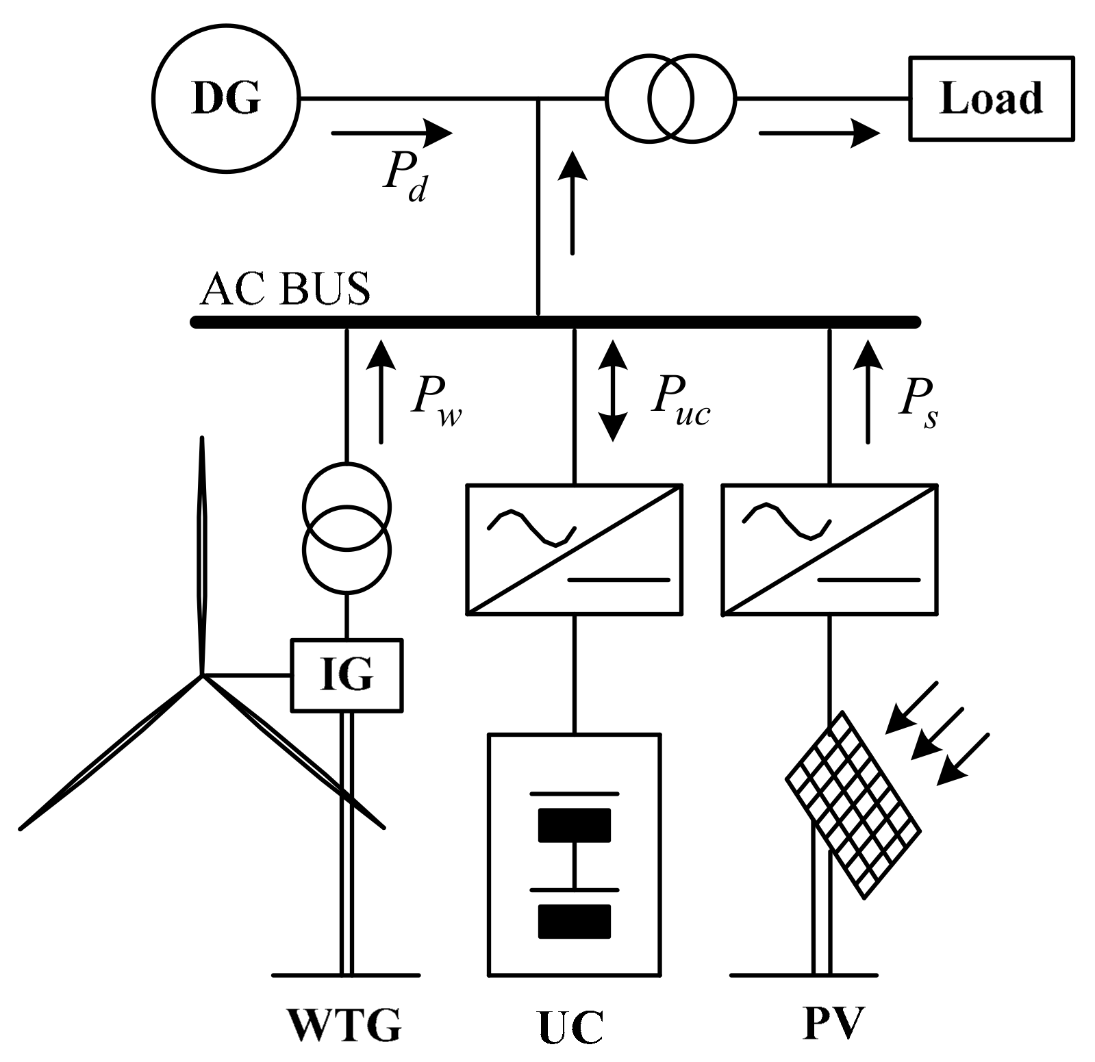
The micro-grid researched in this paper is shown in Figure 1. It is composed of a diesel generator, renewable energy and energy storage unit. Diesel generators, as the traditional power generation source, are connected to the ac bus by a transformer, and their working state should be as stable as possible in order to reduce the fuel consumption and exhaust emissions. The generators are driven by the diesel engine to generate electric power for the system, and the generators’ speed determines the system frequency, which is completely dependent on the diesel engines’ output torque, so the essence of load frequency control is to regulate the diesel engine output power. When a small disturbance acts on the power system and causes a small-range frequency deviation, the speed governor can suppress the deviation adequately, but for a larger disturbance, the primary frequency control is ineffective at bringing the deviation to zero. In this condition, the secondary load frequency control is essential to change the characteristics of the speed governor and finally take the frequency deviation to zero.
As mentioned, the energy storage is indispensable in the micro-grid power system. It has the ability to store the extra power generated by the renewable sources, while providing stored power to the system to maintain the power balance. Many kinds of energy storage forms are tested and utilized in micro-grid power systems, such as batteries, flywheels and ultracapacitors, among which, the battery is the most widely applied to improve the power system stability, but the charge/discharge rate is not satisfactory, while the flywheel has the ability to overcome this disadvantage, but its cost and maintenance are expensive [26]. Therefore, the ultra-capacitor is chosen as the energy storage unit in this paper because of its fast response and low cost. As described in Figure 1, the ultra-capacitor is connected to the ac bus by a dc/ac inverter, and the power in the inverter is bidirectional. If the generated power is much than the demand power, the ultra-capacitor is working in charging mode. Otherwise, the ultra-capacitor is working in discharging mode.
The photovoltaic panel and wind turbine generator are connected to the ac bus by a dc/ac inverter and ac/ac converter, respectively. Both transform the renewable energies into electric power. Due to the fact the power generated by wind and solar deeply depend on the weather conditions, this can be regarded as the unstable factor on the generation side. The power system working in stable state must satisfy the following equation:
In the expression, ∆Pd is the diesel engine output power change, ∆Puc is the ultra-capacitor output power change, ∆Pw is the wind turbine generator output power change, ∆Ps is the photovoltaic output power change, and ∆Pl is the load power change. Because the power in the ultra-capacitor is bidirectional, it is assumed that the power from the ultra-capacitor to the ac bus is positive, and the power from the ac bus to ultra-capacitor is negative.
2.2. Load Frequency Control Model
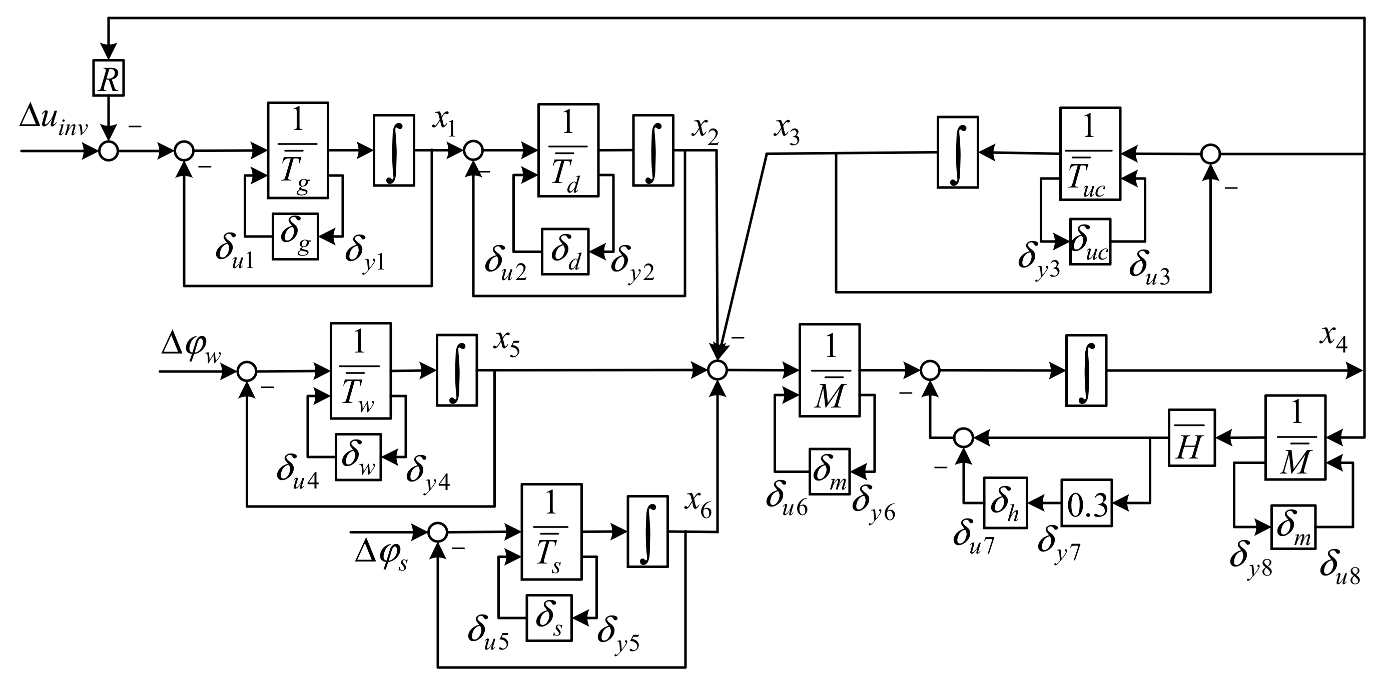
The model of micro-grid frequency control process used in the paper is shown in Figure 2.
In the figure, the Gg(s), Gd(s), Gs(s), Guc(s), Gw(s), Gs(s) are the transfer functions of governor, diesel engine, generator-load, ultra-capacitor, photovoltaic and wind turbine generator. There dynamic characteristics are as follows: the dynamics of the governor are expressed as [36,37,38]:
where, ∆Xg is the governor output, Tg is the governor time constant, ∆u is the control signal, R is the droop coefficient, ∆f is the frequency deviation.
The dynamics of the prime mover are expressed as:
where, ∆Pd is the prime mover output power, and Td is the prime mover time constant.
The power system dynamics are expressed as:
where M is the inertia constant, H is the damping constant.
The dynamics of the ultra-capacitor model are expressed as:
where Tuc is the ultra-capacitor time constant.
The wind turbine generator and photovoltaic panel transform the renewable energy into electric power. The dynamic processes of the two are expressed as [39,40]:
where ∆Pw is the wind turbine generator output power change, ∆ϕw is the wind power change, and Tw is the wind turbine generator time constant:
where ∆Ps is the photovoltaic panel output power change, ∆ϕs is the solar power change, Ts is the photovoltaic panel time constant.
By simultaneously solving Equations (2)–(7), the micro-grid load frequency control state-space model can be written as:
In the model, is the state vector, is the measured output vector, is the disturbance vector, u is the input vector. is the state matrix, is the input matrix, is the output matrix, is the disturbance matrix: Align or replace as in the previous paragraphs as example
The linear state space Equation (8) describes the load frequency control of a micro-grid power system. This is idealized without considered the parameter changes. Due to the environmental effects, such as temperature, electromagnetic interference, equipment aging, the parameters are inevitably perturbed and bring nonlinear factors to the system. With consideration of the parameter perturbation, Equation (8) can be rewritten as:
where, ∆A, ∆B, ∆F are the parameter uncertainties with block-diagonal structure, which have the same dimensions as A, B, F.
Separating the uncertainties from Equation (9), let:
so, Equation (9) is rewritten as:
Without loss of generality, it is assumed that {A,B} is controllable, {A,C} is observable. f(x,t) is norm bounded and meets the Lipschitz condition [29].
3. Controller Designed Based on μ-Synthesis
In this section, the load frequency control model considering parameter perturbation is established, and the robust stability and robust performance indexes are presented.
3.1. Uncertainty Model Establish
Assuming that in the load frequency control system, the parameters Tg, Td, Tuc, Tw, Ts, M, H have perturbation errors, their values change within a certain interval, expressed as:
In the expression, the parameters with over-lines denote the nominal value of the corresponding parameters. The corresponding p and δ in Equation (12) represent the possible perturbations of these seven parameters. In the present study, let p = 0.3, and . This shows that the parameters’ uncertainties are perturbed within ±30%. Considering the parameter perturbation, the load frequency control shown in Figure 2 can be restructured as shown in Figure 3.
Extracting the uncertainties from the actual controlled system, the seven constant blocks in Figure 3 can be replaced by block diagrams in terms of , pg, δg etc., in a unified approach. As introduced in model description section, all the parameters Tg, Td, Tuc, Tw, Ts, M are in the denominator, so they can be represented as a low linear fractional transformation. Taking for example the case of Tg:
with . The parameters Td, Tuc, Tw, Ts, M are similarly transformed using the same method. Especially, the parameter H is in the molecule, and can be represented as a upper linear fractional transformation:
with .
Through the above transformations and substitutions, the interconnection matrix is established; in the matrix, all of the system inputs, uncertainties input, and the system output uncertainties are contained:
where p = 1, 2,…, 6, q = 1, 2,…, 8. is the augmented matrix with nominal model and parameter uncertainty:
3.2. Robust Performance Analysis
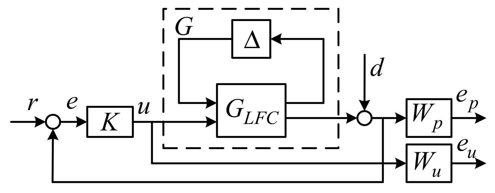
The objective of load frequency control in the paper is to find a feedback control , which makes sure that the closed loop system robust stability and robust performance demands are satisfied. The closed-loop system is shown in Figure 4.
In the figure, is the nominal load frequency control model, ∆ is the uncertainties with block-diagonal structure caused by parameter perturbations, G is transfer function matrix concluded from the nominal model and uncertainties model, G = Fu(GLFC,∆). Wp, Wu are weighting functions, reflecting the frequency characteristics of disturbances and the system performance index. In order to achieve robust stability, the closed-loop system should be internally stable, which satisfies the expression:
In addition to the robust stability, the system should also satisfy the robust performance need, for all the uncertainties:
3.3. DK Iteration
DK iteration is a common method to solve μ-synthesis controller. The steps are the following:
- Step 1:
- Select the initial scale matrix D, generally set D = I;
- Step 2:
- Hold D, and obtain the optimum solution for K via H∞ optimization method. , P is the interconnected augmented matrix include the weighting function and the controlled object.
- Step 3:
- Hold K to solve the convex optimization problem for D at the selected frequency domain and obtain the optimal estimation matrix, mark as . .
- Step 4:
- Let , return to Step 2, repeat steps 2 and 3, until the maximum iteration number is reached, or the constraint is satisfied.
Through the DK iterative process, the controller is solved.
4. Weighting Function Selection Based on Differential Evolution
In this section, the weighting functions in μ-synthesis are determined by a differential evolution method through solving the defined constraint conditions.
4.1. Parameters Setting
The weighting functions not only decide whether the system robust stability and robust performance demands are satisfied, but also play key roles in the DK iterative process. The weighting functions are listed as:
In the expressions, a1,…,a4, b1,…,b4 are undetermined coefficients, and the ranges of parameters are limited to [0, 102]. In order to obtain the optimal parameters, the differential evolution (DE) method is utilized because the method has less parameters to determine and does not easily fall into a local optimum, the DE has better performance than the genetic algorithm and particle swarm optimization [41].
4.2. Determination of Fitness Function
In order to get a better robust stability and robust performance, and also ensure that the closed-loop system has a satisfactory dynamic performance, the fitness function of the differential evolution method should consider all the factors. The selection of the weighting functions is constrained by a series of inequalities:
(1) General indicator
If δ1 < 0, let , if δ1 > 0, let Φ1 = 1000. P is the interconnected augmented matrix that includes the weighting function of the closed-loop system. is the upper bound of the maximum singular value.
(2) Robust stability
If δ2 < 0, let , if δ2 > 0, Φ2 = 1000.
If δ3 < 0, let , if δ3 > 0, let Φ3 = 1000.
(3) Robust performance
If δ4 < 0, let , if δ4 > 0, Φ4 = 1000.
If δ5 < 0, let , if δ5 > 0, let Φ5 = 1000.
(4) Dynamic response performance
The dynamic characteristics and stability margin should be considered to ensure the better output performance as mentioned in [42]; let Φ6 = 10tr, tr be the rise time. , e(t) is the output error, and Ts is the simulation time.
(5) Stability margin
According to [42], for a control system with better stability margin, the amplitude margin should be around 6 dB and the phase margin should be around 45°, thus, the stability margin is defined as follows:
If 6 < Gm < 20, Φ8 = 100/(Gm − 20), else Φ8 = 1000; If 30 < Pm < 60, Φ9 = 100/(Pm − 60), else Φ9 = 1000, where, Gm is the amplitude margin, Pm is the phase margin.
By the abovementioned method, the system performance index are expressed as the inequality constraints, and the objective function is designed as f = ∑Φi, according to the minimum search principle, the fitness function is designed as F = 1/f. For this, the smaller of f, the bigger of F, and F is positive can be guaranteed.
4.3. Algorithm Steps
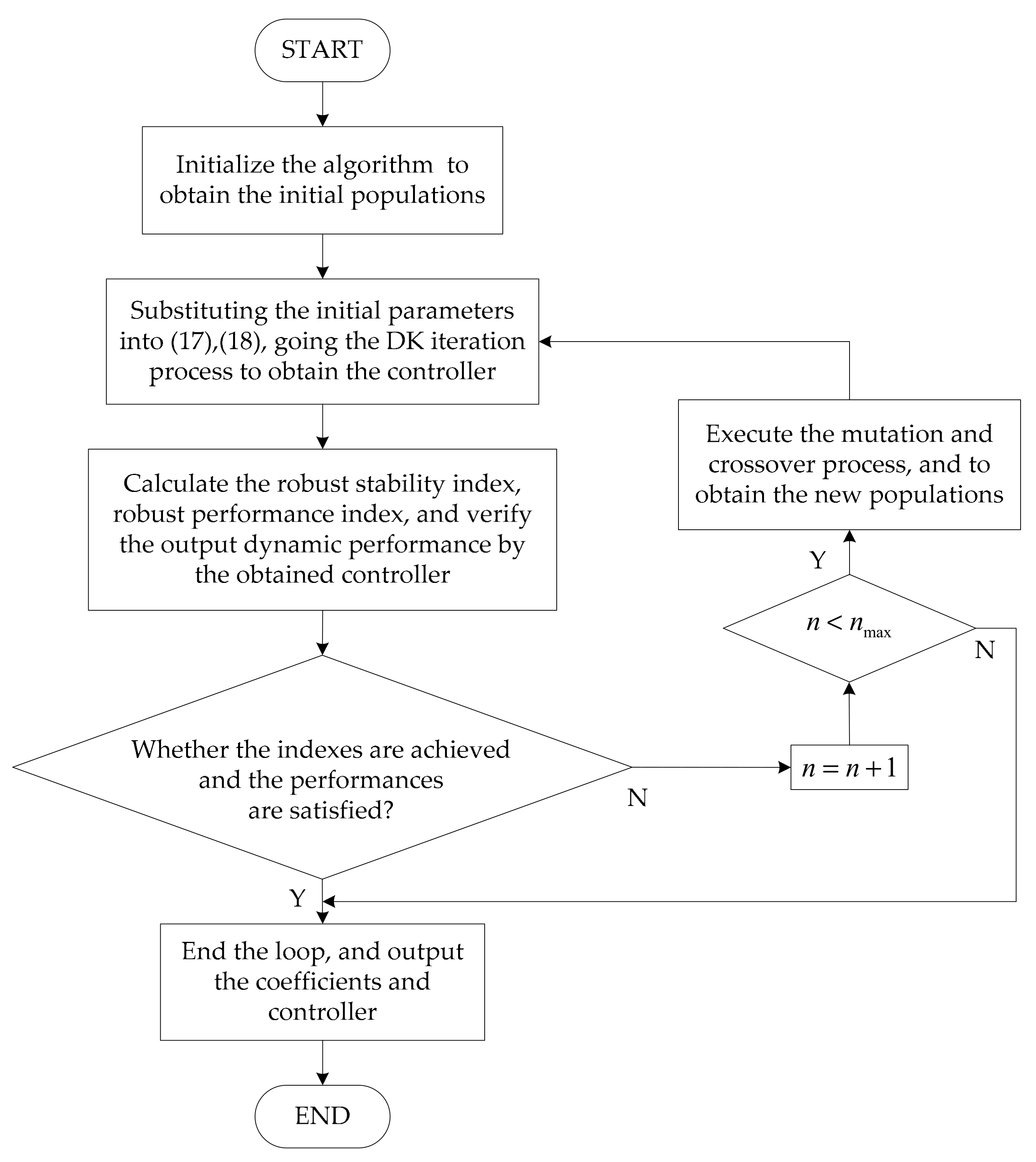
The design steps of micro-grid load frequency robust controller based on differential evolution method are as follows, and the flowchart is shown in Figure 5.
- (1)
- Establish the load frequency control model which concluding the uncertainties.
- (2)
- Initialize the differential evolution algorithm, and obtain the initial populations.
- (3)
- Take the population parameters into the system and going DK iteration process. After iterations, the controller is obtained.
- (4)
- Computing the system robust stability, robust performance and output dynamic performance, and verifying whether the performances are satisfied.
- (5)
- If the performances are not satisfied, then executing the second differential evolution process, and repeat the step 3 and step 4.
The process is done until the desired robust stability and robust performance are achieved and dynamic performance is satisfactory, or the DE iteration is finished.
5. Robust Stability and Robust Performance Analysis
In this section, the robust controller is solved based on the differential evolution algorithm. The algorithm parameters are setting as: number of parameters Dd = 8, population size MG = 50, iteration number GT = 40, variation factor Fr = 0.6, cross factor CR = 0.3. The parameters of micro-grid system are listed in Table 1, the parameters units are expressed as per-units (p.u.).
After the iteration calculation, the weighting function coefficients are obtained, and the structure of weighting functions are shown as:
Taking the designed weighting functions into the closed loop system model, we then execute the DK iteration process to figure out the μ-synthesis controller.
The iteration result is listed in Table 2.
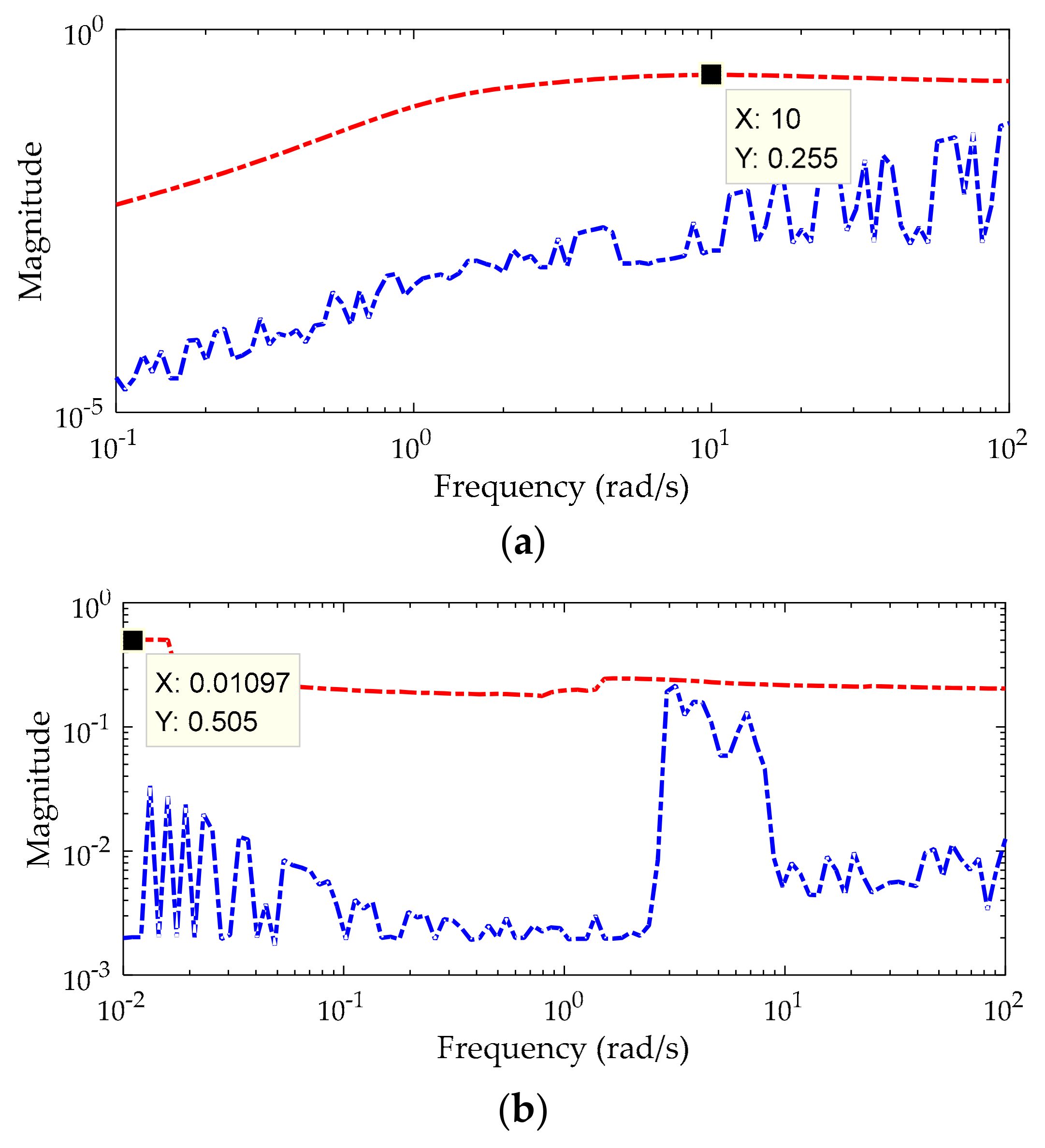
In the table, after the first iteration, the value of μ and γ are larger than 1, which means that the robust stability (RS) and robust performance (RP) are not achieved. After the second iteration, the value of μ and γ are reduced to less than 1, indicating the system robust stability and robust performance have been reached. After the third iteration, the values are further reduced and the system robust stability and robust performance are further improved. As the iterations increase, the values of γ and μ continue to decrease, but the variation is small enough to disregard, and the indexes of robust stability and robust performance are no longer changed. From the table, we also see that the more iterations, the higher the controller orders. In other words, too many iteration calculations will lead to more conservativeness of the controller, and this is unnecessary. Properly, the fifth iteration result is adopted to design the controller to guarantee a compromise between the controller order and robust index.
From Table 2 and Figure 6, the robust stability index is 0.255, what indicates that the system stability is guaranteed for . The robust performance index is 0.505, what indicates that the closed-loop system with the designed controller has achieved both the nominal performance and robust performance since Equation (26), for every diagonal ∆, :
However, the order of controller is still much higher than the order of the plant transfer function. This is means that the implementation of the high order controller requires more hardware (equipment) and this brings more maintenance problems, which greatly increase the cost of the controller and reduce the reliability of the controller, so it is necessary to reduce the controller order to obtain a low order controller. The Hankel-norm approximation method is adopted in the paper to implement the order reduction [43]. After five iterations, the order of controller Kμ is 20, and reduced to 5 by Hankel-norm approximation. The controller transfer function is expressed as:
The comparison of the amplitude-phase frequency characteristic curves is shown in Figure 7, which shows that the full-order controller and the reduced-order control have almost the same frequency characteristics. Thus, compared with the full-order controller, the reduced-order controller is much easier to implement and without performance degradation.
6. Numerical Simulation
In this section, the controller designed by μ-synthesis is simulated and tested. In order to show the effectiveness of the proposed controller, the disturbance power and parameters perturbation are considered in the test. Further to show the robust stability and robust performance, the classic PID controller and H∞ controller [32] are compared with the proposed controller in the simulation.
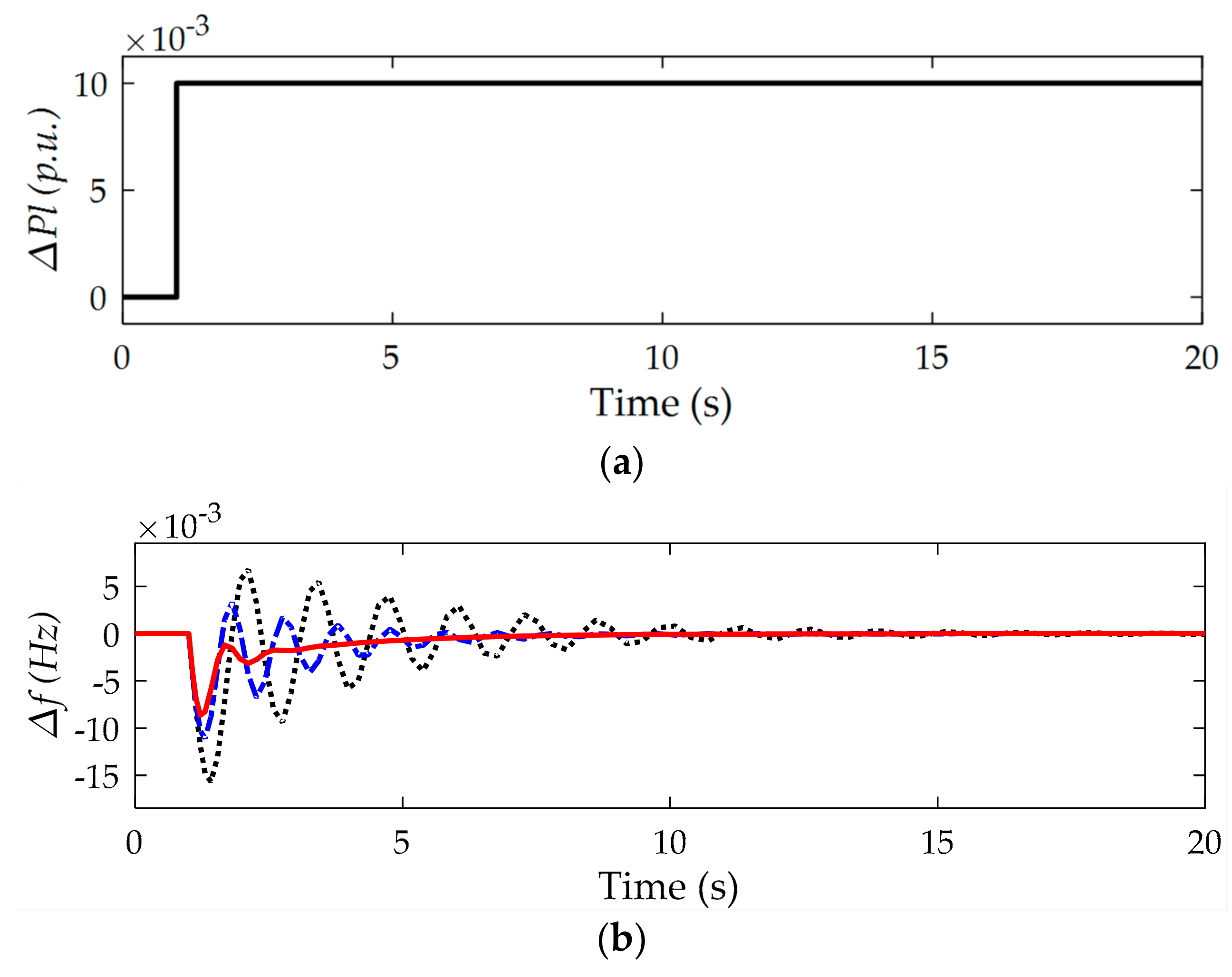
Firstly, in order to demonstrate the ultracapacitor performance, the micro-grids power system without energy storage unit and with battery unit are simulated respectively. We assumed that the system is disturbed by a step power ∆Pl = 0.01p.u., shown as Figure 8a, and the frequency responses are shown as Figure 8b.
From the figures, when the disturbance occurred, the power system without energy storage restored to steady state in about 15 s, and the maximum frequency response is about 0.015 Hz. The stabilization time of the system with battery unit is 7 s, and the overshoot is 0.01 Hz, while for the ultracapacitor unit, the stabilization time is 4 s and the overshoot is 0.008 Hz. The results illustrate that the energy storage units can improve the stability of the micro-grid significantly, and have the ability to reduce the power change. Moreover, due to the fact the ultracapacitor has much faster charge/discharge speed than battery, it is more applicable to absorb the disturbance power with high- frequency and high- power features in the renewable power system.
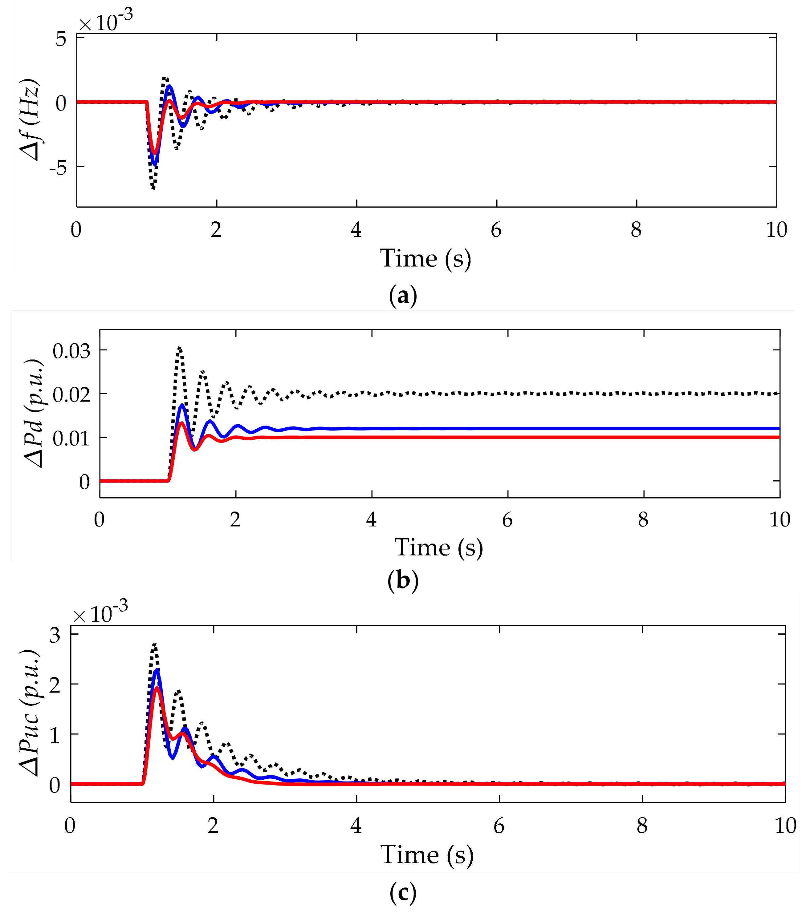
Secondly, we assume that a step signal, which has the same magnitude as in Figure 8a, is given to the renewable energy power system with ultracapacitor. The response results are shown in Figure 9. From the figure, both the H∞ controller and the μ-synthesis control have a faster setting time and smaller overshoot than the optimized PID controller, meanwhile, the μ-synthesis controller has much better performance than the H∞ controller.
Thirdly, considering that due to the fact weather factors lead to power changes in the renewable energies’ output, it is assumed that the sum power deviation of wind and solar change with a five second period in thirty seconds, then the magnitude is as shown in Figure 10a, and the system output responses are as shown in Figure 10. From the figure, the PID controller has a long setting-time and larger overshoot, an even becomes uncontrollable when the change power is bigger. The μ-synthesis controller has better performance than the H∞ no matter how the renewable power changes. Figure 9 and Figure 10 illustrate that the μ-synthesis method has much better robust stability than the H∞ controller.
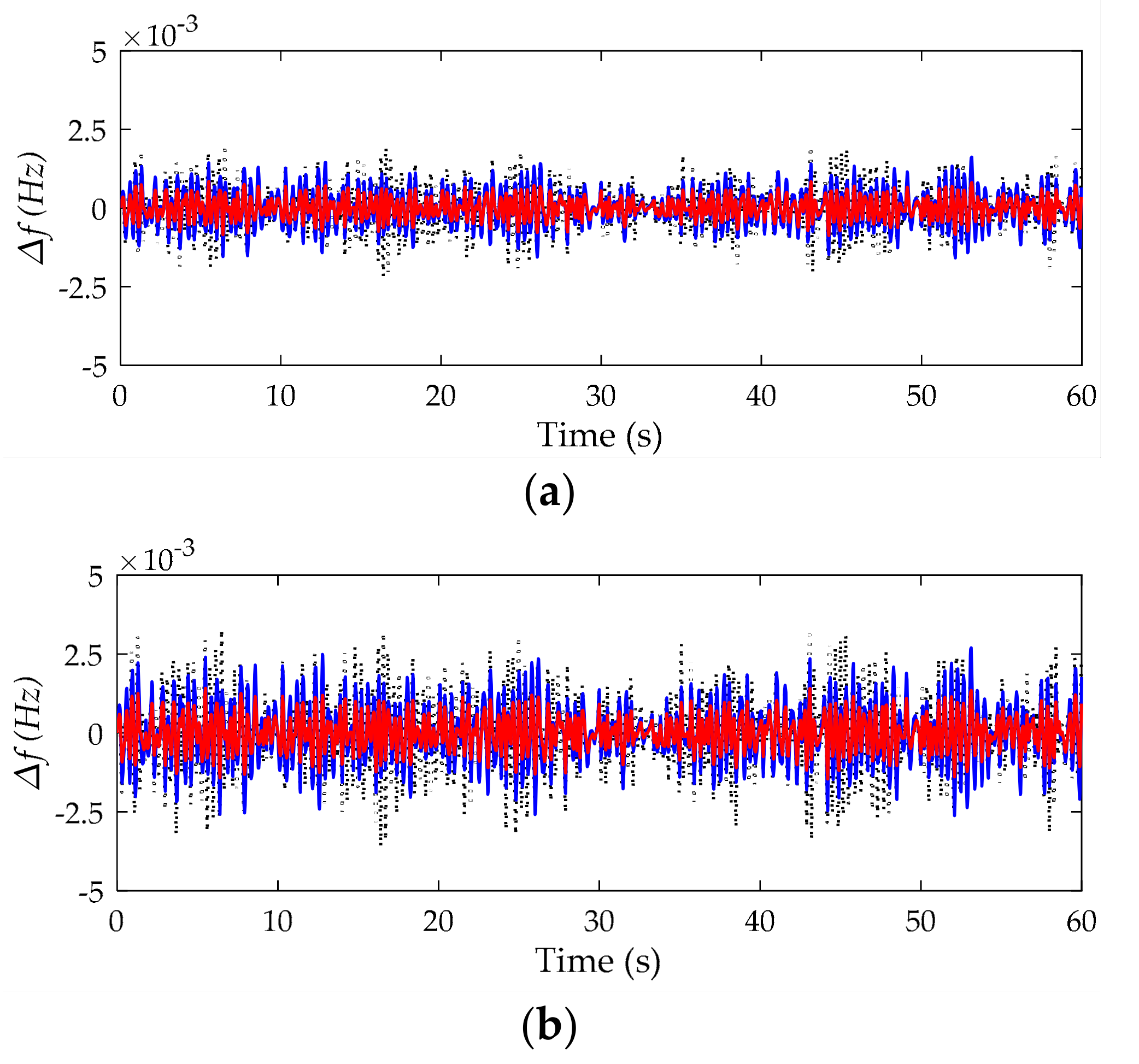
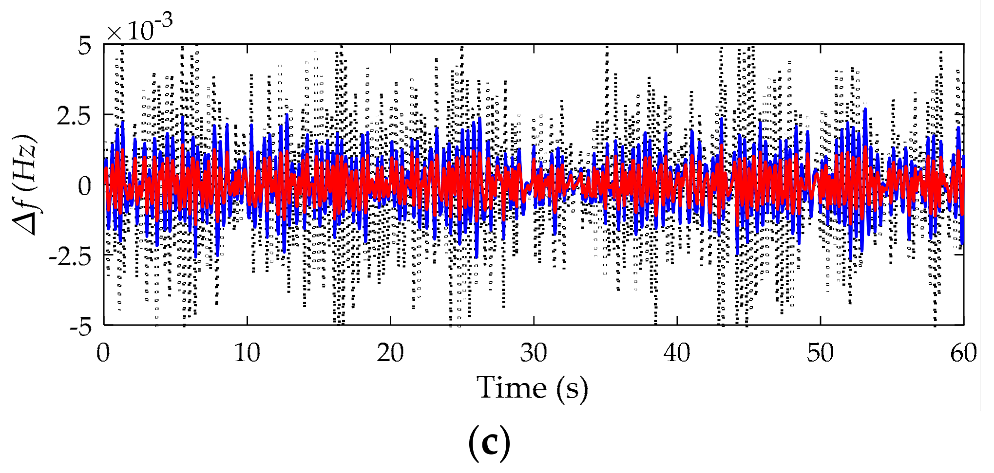
Fourthly, in order to verify the system robust performance, it is assumed that a random external disturbance is applied to the system, and the frequency responses are as shown in Figure 11. From the figure, when the parameters are perturbed within 10%, the fluctuation becomes large, and further when the parameters are perturbed within 30%, the PID controller has become worse, but the H∞ controller and μ-synthesis controller still limit the errors to a tolerable range. The results show that due to the fact the μ-synthesis controller has considered both the structured uncertainty and unstructured uncertainty when designed, it has better robust performance and nominal performance than the H∞ controller, and can greatly improve the load frequency stability of the renewable energy power system.
7. Conclusions
In this paper, the robust μ-synthesis approach is used for load frequency control in a micro-grid power system. The load frequency control state space model with uncertainty is established. The μ-synthesis controller based on structure singular value is designed and solved by the DK iteration method. The controller performances are verified and tested in comparison with the PID controller and H∞ controller. The results show that ultracapacitors can enhance the frequency stability of micro-grid power systems. Due to the fact the μ-synthesis controller has considered both the structured uncertainty and unstructured uncertainty when designed, it has more robust performance and better nominal performance than the H∞ controller, and can greatly improve the load frequency stability of a micro-grid power system.
Author Contributions
Data curation, H.L.; Investigation, H.L., X.W. and J.X.; Methodology, H.L., X.W. and J.X.; Software, H.L.; Supervision, X.W. and J.X.; Writing—original draft, H.L.; Writing—review & editing, H.L.
Funding
This research was funded by the National Natural Science Foundation of China, grant number 61573241 and the Doctorial Innovation Foundation of Shanghai Maritime University, grant number 2016YCX067.
Acknowledgments
The authors gratefully acknowledge the financial support.
Conflicts of Interest
The authors declare no conflict of interest.
References
- Meng, L.; Sanseverino, E.R.; Luna, A.; Dragicevic, T.; Vasquez, J.C.; Guerrero, J.M. Microgrid supervisory controllers and energy management systems: A literature review. Renew. Sustain. Energy Rev. 2016, 60, 1263–1273. [Google Scholar] [CrossRef]
- Wang, C.S.; Liu, Y.X.; Li, X.L.; Guo, L.; Qiao, L.; Lu, H. Energy management system for stand-alone diesel-wind-biomass microgrid with energy storage system. Energy 2016, 97, 90–104. [Google Scholar] [CrossRef]
- Sharma, S.; Bhattacharjee, S.; Bhattacharya, A. Grey wolf optimisation for optimal sizing of battery energy storage device to minimize operation cost of microgrid. IET Gen. Transm. Distrib. 2016, 10, 625–637. [Google Scholar] [CrossRef]
- Zhang, Y.; Li, Y.W. Energy management strategy for supercapacitor in droop-controlled DC microgrid using virtual impedance. IEEE Trans. Power Electron. 2017, 32, 2704–2716. [Google Scholar] [CrossRef]
- Sharma, R.K.; Mishra, S. Dynamic power management and control of PV PEM fuel cell based standalone AC/DC microgrid using hybrid energy storage. IEEE Trans. Ind. Appl. 2017, 54, 526–538. [Google Scholar] [CrossRef]
- Ippolito, M.G.; Telaretti, E.; Zizzo, G.; Graditi, G. A new device for the control and the connection to the grid of combined RES-based generators and electric storage systems. In Proceedings of the International Conference on Clean Electrical Power, Alghero, Italy, 29 August 2013; pp. 262–267. [Google Scholar]
- Pandey, S.K.; Mohanty, S.R.; Kishor, N. A literature survey on load–frequency control for conventional and distribution generation power systems. Renew. Sustain. Energy Rev. 2013, 25, 318–334. [Google Scholar] [CrossRef]
- Mahmoud, M.S.; Hussain, S.A.; Abido, M.A. Modeling and control of microgrid: An overview. J. Frankl. Inst. 2014, 351, 2822–2859. [Google Scholar] [CrossRef]
- Graditi, G.; Ciavarella, R.; Valenti, M. An innovative BESS management for dynamic frequency restoration. In Proceedings of the 2017 IEEE International Conference on Environment and Electrical Engineering and 2017 IEEE Industrial and Commercial Power Systems Europe, Milan, Italy, 6–9 June 2017; pp. 1–5. [Google Scholar]
- Graditi, G.; Ciavarella, R.; Valenti, M.; Ferruzzi, G.; Zizzo, G. Frequency stability in microgrid: Control strategies and analysis of BESS aging effects. In Proceedings of the IEEE International Symposium on Power Electronics, Electrical Drives, Automation and Motion, Anacapri, Italy, 22–24 June 2016; pp. 295–299. [Google Scholar]
- Ou, T.C.; Hong, C.M. Dynamic operation and control of microgrid hybrid power systems. Energy 2014, 66, 314–323. [Google Scholar] [CrossRef]
- Hong, C.M.; Ou, T.C.; Lu, K.H. Development of intelligent MPPT (maximum power point tracking) control for a grid-connected hybrid power generation system. Energy 2013, 50, 270–279. [Google Scholar] [CrossRef]
- Adhikari, S.; Li, F. Coordinated V-F and P-Q control of solar photovoltaic generators with MPPT and battery storage in microgrids. IEEE Trans. Smart Grid 2014, 5, 1270–1281. [Google Scholar] [CrossRef]
- Ou, T.C.; Su, W.F.; Liu, X.Z. A modified bird-mating optimization with hill-climbing for connection decisions of transformers. Energies 2016, 9, 671. [Google Scholar] [CrossRef]
- Ou, T.C. A novel unsymmetrical faults analysis for microgrid distribution systems. Int. J. Electr. Power Energy Syst. 2012, 43, 1017–1024. [Google Scholar] [CrossRef]
- Ou, T.C. Ground fault current analysis with a direct building algorithm for microgrid distribution. Int. J. Electr. Power Energy Syst. 2013, 53, 867–875. [Google Scholar] [CrossRef]
- Ou, T.C.; Lu, K.H.; Huang, C.J. Improvement of Transient Stability in a Hybrid Power Multi-System Using a Designed NIDC (Novel Intelligent Damping Controller). Energies 2017, 10, 488. [Google Scholar] [CrossRef]
- Sathya, M.R.; Ansari, M.T. Load frequency control using Bat inspired algorithm based dual mode gain scheduling of PI controllers for interconnected power system. Int. J. Electr. Power Energy Syst. 2015, 64, 365–374. [Google Scholar] [CrossRef]
- Sönmez, S.; Ayasun, S. Stability region in the parameter space of PI controller for a single-area load frequency control system with time delay. IEEE Trans. Power Syst. 2015, 31, 829–830. [Google Scholar] [CrossRef]
- Zamani, A.; Barakati, S.M.; Yousofidarmian, S. Design of a fractional order PID controller using GBMO algorithm for load-frequency control with governor saturation consideration. ISA Trans. 2016, 64, 56–66. [Google Scholar] [CrossRef] [PubMed]
- Pradhan, P.C.; Sahu, R.K.; Panda, S. Firefly algorithm optimized fuzzy PID controller for AGC of multi-area multi-source power systems with UPFC and SMES. Eng. Sci. Technol. 2016, 19, 338–354. [Google Scholar] [CrossRef]
- Zhang, S.; Mishra, Y.; Shahidehpour, M. Fuzzy-logic based frequency controller for wind farms augmented with energy storage systems. IEEE Trans. Power Syst. 2016, 31, 1595–1603. [Google Scholar] [CrossRef]
- Mahto, T.; Mukherjee, V. A novel scaling factor based fuzzy logic controller for frequency control of an isolated hybrid power system. Energy 2017, 130, 339–350. [Google Scholar] [CrossRef]
- Vachirasricirikul, S.; Ngamroo, I. Robust LFC in a smart grid with wind power penetration by coordinated V2G control and frequency controller. IEEE Trans. Smart Grid 2017, 5, 371–380. [Google Scholar] [CrossRef]
- Yang, J.; Zeng, Z.; Tang, Y.; Yan, J.; He, H.; Wu, Y. Load frequency control in isolated micro-grid with electrical vehicle based on multivariable generalized predictive theory. Energies 2015, 8, 2145–2164. [Google Scholar] [CrossRef]
- Shankar, R.; Chatterjee, K.; Bhushan, R. Impact of energy storage system on load frequency control for diverse sources of interconnected power system in deregulated power environment. Int. J. Electr. Power Energy Syst. 2016, 79, 11–26. [Google Scholar] [CrossRef]
- Ma, M.; Zhang, C.; Liu, X.; Chen, H. Distributed model predictive load frequency control of the multi-area power system after deregulation. IEEE Trans. Ind. Electron. 2017, 64, 5129–5139. [Google Scholar] [CrossRef]
- Rinaldi, G.; Cucuzzella, M.; Ferrara, A. Third order sliding mode observer-based approach for distributed optimal load frequency control. IEEE Control Syst. Lett. 2017, 1, 215–220. [Google Scholar] [CrossRef]
- Mu, C.; Tang, Y.; He, H. Improved sliding mode design for load frequency control of power system integrated an adaptive learning strategy. IEEE Trans. Ind. Electron. 2017, 64, 6742–6751. [Google Scholar] [CrossRef]
- Fu, C.; Tan, W. Decentralized load frequency control for power systems with communication delays via active disturbance rejection. IET Gen. Transm. Distrib. 2017, 12, 1397–1403. [Google Scholar]
- Zhang, C.K.; Jiang, L.; Wu, Q.H.; He, Y.; Wu, M. Delay-dependent robust load frequency control for time delay power systems. IEEE Trans. Power Syst. 2013, 28, 2192–2201. [Google Scholar] [CrossRef]
- Ning, C. Robust H∞ load-frequency control in interconnected power systems. IET Control Theory Appl. 2016, 10, 67–75. [Google Scholar]
- Han, Y.; Young, P.M.; Jain, A.; Daniel, Z. Robust control for microgrid frequency deviation reduction with attached storage system. IEEE Trans. Smart Grid 2015, 6, 557–565. [Google Scholar] [CrossRef]
- Zhao, J.; Xue, L.; Fu, Y.; Hu, X.G.; Li, F.X. Coordinated microgrid frequency regulation based on DFIG variable coefficient using virtual inertia and primary frequency control. IEEE Trans. Energy Convers. 2016, 31, 833–845. [Google Scholar] [CrossRef]
- Bevrani, H.; Feizi, M.R.; Ataee, S. Robust Frequency Control in an Islanded Microgrid: H∞ and μ-Synthesis Approaches. IEEE Trans. Smart Grid 2016, 7, 706–717. [Google Scholar] [CrossRef]
- Zhu, D.; Hug-Glanzmann, G. Coordination of storage and generation in power system frequency control using an H∞ approach. IET Gen. Transm. Distrib. 2013, 7, 1263–1271. [Google Scholar] [CrossRef]
- Pandey, S.K.; Mohanty, S.R.; Kishor, N.; Catalão, J.P.S. Frequency regulation in hybrid power systems using particle swarm optimization and linear matrix inequalities based robust controller design. Int. J. Electr. Power Energy Syst. 2014, 63, 887–900. [Google Scholar] [CrossRef]
- Sasaki, T.; Kadoya, T.; Enomoto, K. Study on load frequency control using redox flow batteries. IEEE Trans. Power Syst. 2004, 19, 660–667. [Google Scholar] [CrossRef]
- Jayalakshmi, N.S.; Gaonkar, D.N. Performance study of isolated hybrid power system with multiple generation and energy storage units. In Proceedings of the 2011 International Conference on Power and Energy Systems, Chennai, India, 22–24 December 2011; pp. 1–5. [Google Scholar]
- Mohanty, S.R.; Kishor, N.; Ray, P.K. Robust H-infinite loop shaping controller based on hybrid PSO and harmonic search for frequency regulation in hybrid distributed generation system. Int. J. Electr. Power Energy Syst. 2014, 60, 302–316. [Google Scholar] [CrossRef]
- Das, S.; Suganthan, P.N. Differential Evolution: A Survey of the State-of-the-Art. IEEE Trans. Evolut. Comput. 2011, 15, 4–31. [Google Scholar] [CrossRef]
- Shousong, H. Automatic Control Theory, 4th ed.; Science: Beijing, China, 2001; pp. 201–213. [Google Scholar]
- Dawei, G.; Petkov, P.H.; Konstantinov, M.M. Robust Control Design with MATLAB; Springer: New York, NY, USA, 2005; pp. 158–161. [Google Scholar]
Figure 1.
Micro-grid power system structure.

Figure 2.
Load frequency control.
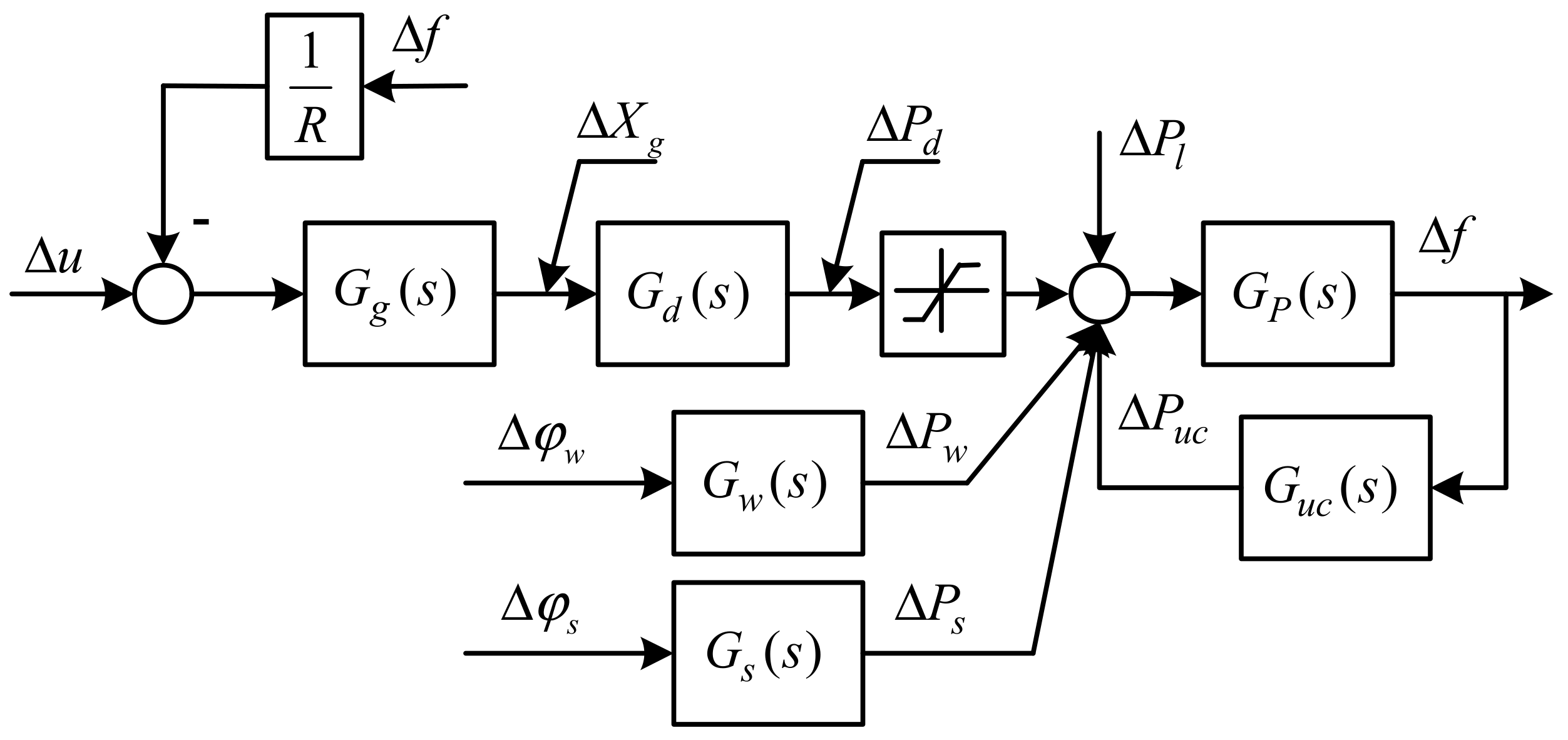
Figure 3.
Load Frequency Control System with Uncertainty.

Figure 4.
Closed-loop system structure.

Figure 5.
Flowchart of the proposed method.

Figure 6.
The index of robust stability and robust performance, (a) the robust stability of controller, upper bound (red) and lower bound (blue); (b) the robust performance of perturbed system, upper bound (red) and lower bound (blue).
Figure 6.
The index of robust stability and robust performance, (a) the robust stability of controller, upper bound (red) and lower bound (blue); (b) the robust performance of perturbed system, upper bound (red) and lower bound (blue).

Figure 7.
Bode diagram of the full-order controller (red) and reduced−order controller (blue).
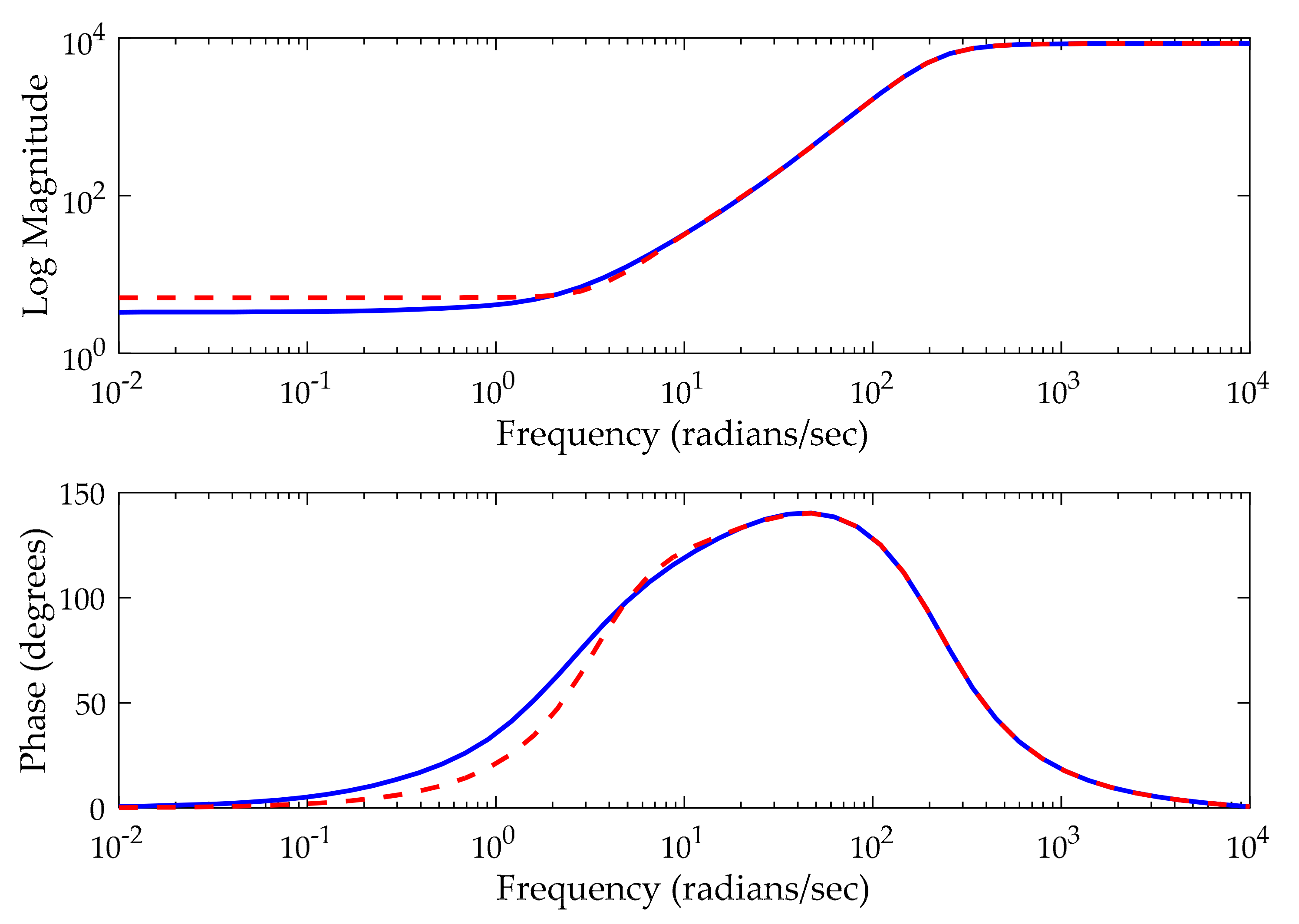
Figure 8.
The power system frequency deviation disturbed by the step signal, without energy storage unit (black-dotted), with battery (blue-dashed), and with ultra-capacitor (red-solid), (a) the step signal; (b) the frequency deviation.
Figure 8.
The power system frequency deviation disturbed by the step signal, without energy storage unit (black-dotted), with battery (blue-dashed), and with ultra-capacitor (red-solid), (a) the step signal; (b) the frequency deviation.

Figure 9.
The system outputs with step signal, proportion integral derivative (PID) control (black), H∞ control (blue) and μ-synthesis control (red), (a) frequency deviation; (b) diesel engine power deviation; (c) ultra-capacitor power deviation.
Figure 9.
The system outputs with step signal, proportion integral derivative (PID) control (black), H∞ control (blue) and μ-synthesis control (red), (a) frequency deviation; (b) diesel engine power deviation; (c) ultra-capacitor power deviation.

Figure 10.
Outputs response with renewable energies power change by PID control (black), H∞ control (blue) and μ-synthesis control (red), (a) renewable energies power change; (b) frequency deviation; (c) diesel engine power deviation; (d) ultra-capacitor power deviation.
Figure 10.
Outputs response with renewable energies power change by PID control (black), H∞ control (blue) and μ-synthesis control (red), (a) renewable energies power change; (b) frequency deviation; (c) diesel engine power deviation; (d) ultra-capacitor power deviation.
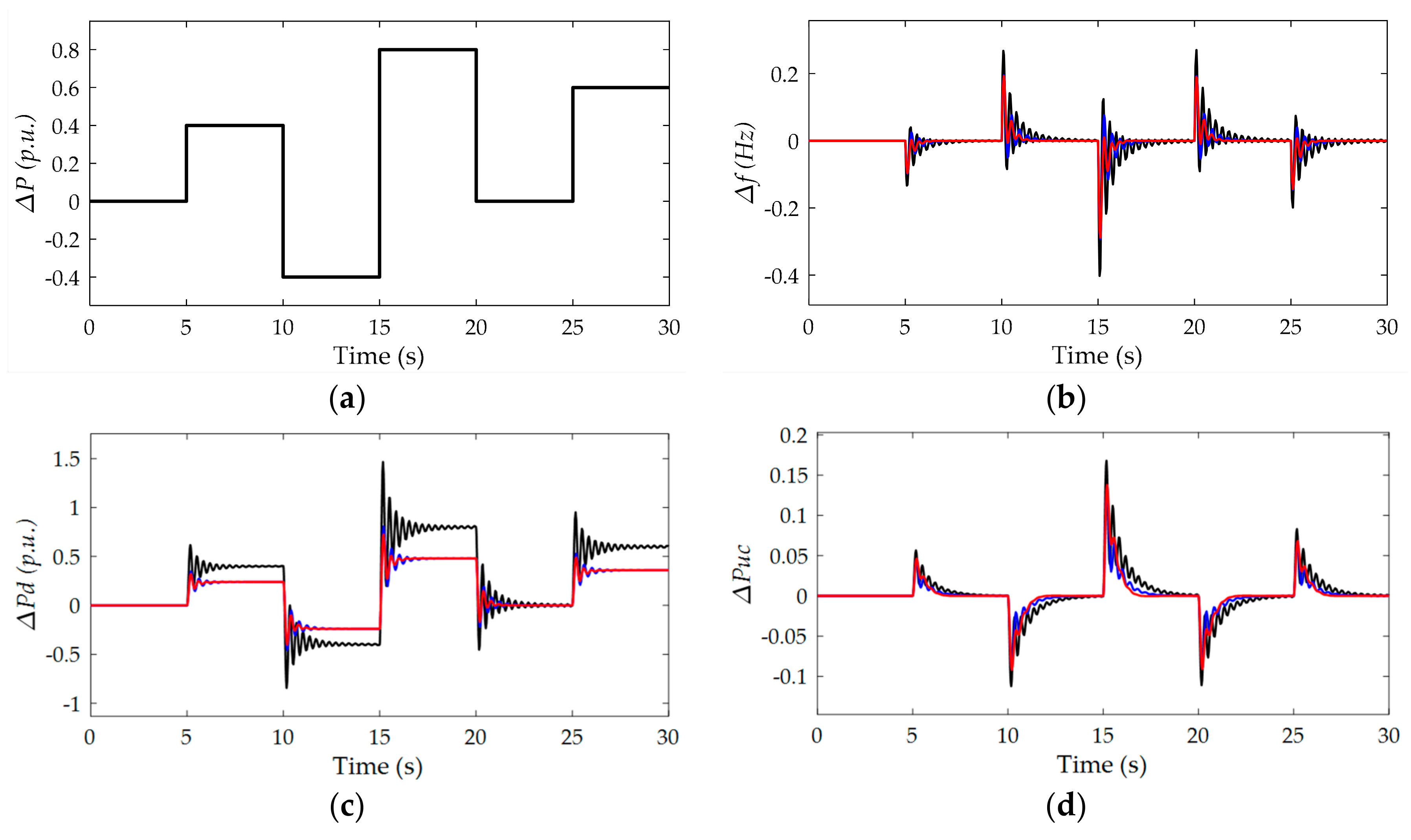
Figure 11.
Frequency deviation with parameters perturbation, PID control (black), H∞ control (blue) and μ-synthesis control (red), (a) without parameters perturbation; (b) parameters perturbed within 10%; (c) parameters perturbed within 30%.
Figure 11.
Frequency deviation with parameters perturbation, PID control (black), H∞ control (blue) and μ-synthesis control (red), (a) without parameters perturbation; (b) parameters perturbed within 10%; (c) parameters perturbed within 30%.


Table 1.
System parameters.
| Parameter Name | Value |
|---|---|
| Rated Frequency (Hz) | 50 |
| Rated power (MW) | 2 |
| Governor Time Constant Tg (s) | 0.008 |
| Diesel Time Constant Td (s) | 0.3 |
| Ultracapacitor Time Constant Tuc (s) | 0.1 |
| wind turbine generator time constant Tw (s) | 1.5 |
| photovoltaic panel time constant Ts (s) | 1.8 |
| Inertia coefficient M (p.u./s) | 0.15 |
| Damping coefficient H (p.u./Hz) | 0.008 |
| Droop coefficient R (p.u./Hz) | 2.4 |
Table 2.
DK iteration results.
| Iterations | K Order | D Order | γ Value | μ Value | μ-RS | μ-RP |
|---|---|---|---|---|---|---|
| 1 | 6 | 0 | 8.777 | 1.498 | 1.172 | 1.3516 |
| 2 | 8 | 2 | 0.744 | 0.520 | 0.549 | 0.817 |
| 3 | 12 | 6 | 0.439 | 0.436 | 0.255 | 0.505 |
| 4 | 20 | 14 | 0.390 | 0.389 | 0.255 | 0.505 |
| 5 | 20 | 14 | 0.369 | 0.369 | 0.255 | 0.505 |
| 6 | 30 | 24 | 0.360 | 0.359 | 0.255 | 0.505 |
| 7 | 30 | 24 | 0.353 | 0.352 | 0.255 | 0.505 |
| 8 | 32 | 26 | 0.349 | 0.349 | 0.255 | 0.505 |
| 9 | 32 | 26 | 0.348 | 0.348 | 0.255 | 0.505 |
| 10 | 34 | 28 | 0.347 | 0.347 | 0.255 | 0.505 |
© 2018 by the authors. Licensee MDPI, Basel, Switzerland. This article is an open access article distributed under the terms and conditions of the Creative Commons Attribution (CC BY) license (http://creativecommons.org/licenses/by/4.0/).
Share and Cite
MDPI and ACS Style
Li, H.; Wang, X.; Xiao, J. Differential Evolution-Based Load Frequency Robust Control for Micro-Grids with Energy Storage Systems. Energies 2018, 11, 1686. https://doi.org/10.3390/en11071686
AMA Style
Li H, Wang X, Xiao J. Differential Evolution-Based Load Frequency Robust Control for Micro-Grids with Energy Storage Systems. Energies. 2018; 11(7):1686. https://doi.org/10.3390/en11071686
Chicago/Turabian StyleLi, Hongyue, Xihuai Wang, and Jianmei Xiao. 2018. "Differential Evolution-Based Load Frequency Robust Control for Micro-Grids with Energy Storage Systems" Energies 11, no. 7: 1686. https://doi.org/10.3390/en11071686
Note that from the first issue of 2016, this journal uses article numbers instead of page numbers. See further details here.