Article

A Novel Electromagnetic Coupling Reactor Based Passive Power Filter with Dynamic Tunable Function

School of Automation, Wuhan University of Technology, Wuhan 430070, China
*
Author to whom correspondence should be addressed.
Energies 2018, 11(7), 1647; https://doi.org/10.3390/en11071647
Submission received: 22 May 2018 / Revised: 19 June 2018 / Accepted: 20 June 2018 / Published: 25 June 2018

Abstract

:
Along with massive applications of power electronic equipment and non-linear loads, harmonic pollutions are becoming more serious than ever. This paper describes a novel electromagnetic coupling reactor based passive power filter with dynamic tuning to quickly eliminate harmony. Firstly, the structure and mathematic model of electromagnetic coupling reactor are presented; secondly, the employed parameters, including electromagnetic coupling reactance converter, primary winding coil, and secondary winding coil are designed based on a stable structure of data; then, the test plat of passive dynamic tunable filter is introduced, as well as the performance test. According to the experimental results, the newly designed electromagnetic coupling reactor can effectively eliminate the harmonies generated by the nonlinear load, greatly reducing the harm caused by harmonics on the grid. By fine-tuning the electromagnetic coupling reactor, the dissonance caused by the change of capacitance and other issues can be effectively solved. Finally, the detailed discussion of this paper is presented, and challenges and new future research are discussed.

1. Introduction

With more and more non-linear devices such as direct current (DC) motors, DC power supplies, variable-frequency governors, rectifying installations, etc. used in the power grid, the level of harmonics also increases, requiring stricter controls on power quality [1,2]. Results show that increased harmonic components will shorten the life span of electrical equipment, increase network energy loss, and increase the possibility of the occurrence of resonance in the power system. Because of the severe pollution of electrical network harmonics such as power grid loss, the instability of large converter equipment, the effectiveness of communication system etc., harmonic restraint has become an important task for the power supply bureau [3]. The best solution to the harmonic problems is to install the power filters at sources, as well as at the closest terminals of power networks [4]. There are three different filter types, namely, passive power filter, active power filter, and hybrid active power filter.
The passive power filter (PF) utilizes the combination of inductor L, capacitor C, and resistor R to form a filter circuit. The low-impedance (tuned filter) state of a certain harmonic is connected in parallel with the inductance and the capacitance to a certain harmonic current, forming a low-impedance path [5,6]. Though PF has the advantages of simple structure, high capacity, low cost, and stable performance, its disadvantages are also obvious, and its energy-storage element is large in bulk. Moreover, it may produce a series of resonances and parallel resonances within the power grid. Furthermore, harmonic waves cannot be filtered rapidly in real time. Filtering performance relies on the parameters of power grid and load, and is significantly influenced by environment and capacitance devices.
Compared with the PF, the active power filter (APF) is another novel power electronic device capable of dynamically inhibiting harmonics. When a system harmonic wave is detected, the APF will immediately generate a set of harmonic vectors with the same amplitude and opposite phase, with the system harmonic wave to offset it, making it a sine wave [7]. APF can not only dynamically filter harmonics, but can also automatically track and compensate the varying harmonic currents in power grid. It has a high controllability and response. Moreover, its compensation performance is not affected by the frequency fluctuations of power grid, and its filtering performance is not affected by system impedance [8,9,10,11]. APF can avoid generating resonance with the system impedance, and thus, is quite effective in harmonic control. However, APF control is more complex in control systems, the price is relatively high, the operating conditions are harsh, and it is highly restricted by hardware devices, so APF usually operates in only small capacity cases.
Hybrid active power filters (HAPFs) are a combination of an APF and LC PF. The APF is in parallel connection with several LC PPFs, which filter most of the harmonics, with the rest of the harmonics filtered by the APF [12]. HAPF can effectively compensate reactive power loss, as well as load harmonic current based on the advantages of both APF and PPF. However, due to the increase of parallel branch, the control algorithm is complex, and the security and reliability of system cannot be guaranteed.
In conclusion, the three filters are suitable for different applications, based on their strengths. However, they are limited to specific scenarios due to such disadvantages as high price, instability, and poor real-time performance [13,14,15]. Developing a filter that combines the advantages of APF and PF has always been a focus of researchers. For this purpose, this paper designs an electromagnetic coupling reactor to replace the L of traditional PF, and develops a passive dynamic tunable filter using the electromagnetic coupling reactor to dynamically adjust the inductance L. The proposed tunable filter can automatically track and compensate the varying harmonic currents in power grid, with the harmonics filtered out rapidly in real time. The filtering performance will not be affected by the parameters of load and power grid. The contradiction between filtering performance and product costs can be resolved by fixing the resonance point. The rest of the paper is organized as follows. First, Section 2 presents the structure and mathematic model of electromagnetic coupling reactor. Then, the employed parameters, including nominal parameter, insulation radius, window height of iron core and coil of primary impedance winding, are designed based on a stable structure of data in Section 3. Next, Section 4 designs an electromagnetic coupling reactor for reducing the harm caused by harmonics on the grid. Finally, Section 5 concludes this paper with further discussion.

2. Structure and Mathematic Model of Electromagnetic Coupling Reactor

A traditional iron-core reactor can be applied in current limiting, motor starting, passive filtering and reactive compensation. However, the inductance (or impedance) cannot be continuously adjusted, with the application greatly limited [16,17,18]. To solve this problem, this paper redesigns the traditional iron-core reactor and develops it into an electromagnetic coupling reactance converter which has primary winding and secondary winding, and is connected with power electronic impedance converter. Then, a novel electromagnetic coupling reactor composed of a reactance converter and an electronic impedance converter is built.

2.1. Topological Structure of Electromagnetic Coupling Reactance Converter

Figure 1 shows the schematic diagram and topological structure of the electromagnetic coupling reactance converter (ECRC). In Figure 1a, A X is the primary winding of electromagnetic coupling reactance converter, N 1 is the number of turns, U 1 is voltage, and i 1 is electric current; a x is the secondary winding of electromagnetic coupling reactance converter, N 2 is the number of turns, U 2 is voltage, and i 2 is electric current. More details about the schematic diagram and topological structure of the electromagnetic coupling reactance converter can be found in [19,20,21,22].
Due to the refractory nature of the reactance converter, the converter is unsaturated and works in a linear region. The voltage, current, and leakage reactance of the reactance winding are converted to the secondary reactance winding. ( I . 1 = k I . 1 ; Z 1 = Z 1 / k 2 ; U . 1 = U . 1 / k ). M denotes the mutual inductance of primary winding coil and secondary winding coil; L 11 and L 22 are the self-inductances of primary winding coil and secondary winding coil, respectively. Then, the flowing equations can be derived through Kirchhoff’s law:
U . 1 = I . 1 k 2 [ r 1 + j ω ( L 11 k M ) ] + ( I . 1 + I . 2 ) j ω M k = Z 1 I 1 + Z m I m
U . 2 = I . 2 [ r 2 + j ω ( L 11 M k ) ] + ( k I . 1 + I . 2 ) j ω M k = Z 2 I 2 . + Z m I m
where r 1 and r 2 respectively denote the equivalent winding resistances of primary winding coil and secondary winding coil; k is the ratio of turns; Z 1 , Z 2 and Z m respectively are the leakage reactance of primary winding coil, the leakage reactance of secondary winding coil, and the excitation impedance of main flux circuit. They can be written as: Z 1 = r 1 + j ω ( L 11 k M ) , Z 2 = r 2 + j ω ( L 22 M k ) , Z m = j ω M / k . I m = k I . 1 + I . 2 is the exciting current in the main magnetic flux loop.

2.2. Mathematic Model design of Electromagnetic Coupling Reactor

A power electronic impedance converter (antiparallel thyristor) was connected to the secondary winding of the electromagnetic coupling reactance converter, forming an electromagnetic coupling reactor [23]. The structure of the electromagnetic coupling reactor shown in Figure 2 has three operating modes, namely, turn-off mode, short-circuited mode, and regulation mode.
The current of the secondary winding I2 is zero when the ax end of the secondary winding is in the turn-off mode. This means that the impedance is the largest when the secondary impedance converter is unloaded, and the same goes for the primary winding. Thus, the voltage across both ends of Load Z is the smallest. Then there is:
Z 11 max = U 1 . I 1 = Z 1 + Z m = Z 1 k 2 + Z m
When the ax end of the secondary winding of electromagnetic coupling reactance converter is in the short-circuited mode, the voltage of secondary winding U 2 is zero. Then:
Z 11 min = U 1 . I 1 = Z 1 + Z m = Z 1 k 2 + β Z 2
Different from the above two modes, the voltage U 2 and current I 2 of secondary winding are both nonzero when the thyristor works between “cut-off and breakover.” There exists:
Z 11 = U 1 . I 1 = Z 1 + Z m / / ( Z 2 + Z α ) = Z 1 ( Z m + Z 2 + Z α ) + Z m ( Z 2 + Z α ) Z m + Z 2 + Z α
The voltage across the power electronic impedance converter is:
u 2 = 2 U 2 sin ω t
In the thyristor work state, the positive and negative half-waves of current waveform of secondary winding are symmetrical, free from direct component and even-order harmonic. According to Fourier formula, the current of secondary winding is expressed as:
i 2 ( ω t ) = n = 1 , 3 , 5 ( a n cos n ω t + b n sin n ω t )
where
a 1 = 2 π a π i 2 ( ω t ) cos ω t d ( ω t ) = 2 π a π 2 U 2 Z a cos ω t d ( ω t ) = 2 U 2 2 π Z a ( cos 2 a 1 )
b 1 = 2 π a π i 2 ( ω t ) sin ω t d ( ω t ) = 2 U 2 2 π Z a [ sin 2 a + 2 ( π a ) ]
a 3 = 2 U 2 π Z a [ 1 4 cos 4 a 1 2 cos 2 a + 1 2 ]
b 3 = 2 U 2 2 π Z a [ 1 4 sin 4 a 1 2 sin 2 a ]
a 1 a 3 and a 3 being ignored, b 1 b 3 , b 3 can be ignored. Similarly, a 3 , a 5 , a 7 , , which is far less than a 1 , and b 5 , b 7 , , which is far less than b 1 are ignored. Then Equation (7) is simplified into:
i 2 ( ω t ) = a 1 cos ω t + b 1 sin ω t
The effective value of I 2 is:
I 2 = 1 2 a 1 2 + b 1 2 = U 2 , π Z 2 , sin 2 a + ( π a ) sin 2 a + ( π a ) 2
From Equation (13), get Z a :
Z a = U 2 , I 2 = π Z 2 , sin 2 a + ( π a ) sin 2 a + ( π a ) 2
It can be known from Equation (14) that, when the control angle of the power electronic impedance converter changes, its equivalent impedance will change as well. Here the converter can be seen as the variable impedance Z a . The curve of the impedance modulus which changes with the control angle a of the thyristor is shown in Figure 3.
In Figure 3, the impedance of electronic impedance converter will increase along with the control angle of thyristor a. When the control angle ranges within 0~140, the impedance of power electronic impedance converter changes slowly; when the control angle ranges within 140~170, the change in the impedance becomes obvious; when the control angle ranges within 170~180, a sharp increase is observed in the impedance.
Equations (4)–(6), and (14) directly show the correlation between the equivalent impedance of primary winding of electromagnetic coupling reactor and the thyristor trigger angle of secondary winding. When the trigger angle of power electronic impedance converter changes, the electromagnetic coupling reactor can be seen as a variable impedance Z 11 which meets Z 11 min Z 11 Z 11 max .

3. Parameter Design of Electromagnetic Coupling Reactance Converter

The parameter design of ECRC plays a very important role in the electromagnetic coupling reactor design. Next, a detailed analysis and discussion will be presented in terms of three important aspects.

3.1. Parameter Design of Electromagnetic Coupling Reactance Converter

The sectional area S of iron core:
S = π ( D 2 ) 2 × α 1 × α 2
where D denotes the diameter of iron core, α 1 and α 2 are the technological coefficient of lamination and gross section coefficient respectively. Generally, α 1 ranges within 0.93~0.98 (usually 0.95), and α 2 is 0.91.
Potential of primary turns e F 0 :
e F 0 = β 0 × S C
where β 0 is the primary flux density which varies according to the materials and usually ranges within 15,000~19,000 GS (slightly higher for cold-rolled plate; 12,000~16,000 GS for hot-rolled plate). C is 450, the constant corresponding to 50 Hz.
(1)
The number of turns of primary winding W 1 :
W 1 = k 0 U L 1 e F 0
where denotes ceiling (a slightly larger value is allowed).
(2)
The number of turns of secondary winding W 2 :
W 2 = W 1 n
(3)
Potential of final turns e F :
e F = k 0 U L 1 W 1

3.2. Parameter Design of Primary Winding Coil

The sectional area of coil of primary winding (unifilar winding) S 1 is:
S 1 = δ 1 × X B 1 × X H 1
where δ 1 is the intended layers of coil of primary winding. Generally, there are 8 layers (meets the requirement of W2 = 460 turns) and each layer has W 1 / δ 1 turns, and X B 1 and X H 1 are the thickness and width of bare copper wire respectively. The flat copper wire is covered with ZB-0.45 paper. Generally, ZB-0.45 is for 10 kV, ZB-0.65 is for 35 kV, and ZB-0.95 is for 110 kV. The thickness and width of bare copper wire are 1.8 mm and 7.1 mm respectively.
The electric current density is:
J 1 = I L 1 S 1
The window height of iron core H W 1 :
H W 1 = H x q s 1 + L u p 1 + L d o w n 1
where L u p 1 and L d o w n 1 are the upper insulation distance and lower insulation distance (the values assigned are 26.5 mm) respectively, with H x q s 1 being the actual height of coil and its calculation formula obtained:
H x q s 1 = ( X H 1 + δ 0 ) × ( W 1 / δ 1 + 1   ) + ρ c r 1
where ρ c r 1 is the margin of coil (the value assigned is 2.4 mm).

3.3. Parameter Design of Secondary Winding Coil

The sectional area of the coil of secondary winding (bifilar winding) S 2 is:
S 2 = e 2 × X B 2 × X H 2
where e 2 refers to the intended layers of coil of secondary winding (each layer has W 2 / e 2 turns), which is usually assigned to 2 (meets the requirement of W 2 ), and X B 2 and X H 2 refer to the thickness and width of the bare flat copper wire used in secondary winding, respectively. Generally, the flat copper wire is covered with ZB-0.45 paper, with the thickness and width of bare copper wire 3.35 mm and 7.5 mm, respectively.
The electric current density J 2 :
J 2 = I L 2 S 2
Generally, the J 2 of oil-immersed filter reactor (for long-term service) is 3~4 A/mm2 and the J 2 of dry-type one is 1.5~2 A/mm2.
The insulation radius between the center lines of iron cores r 0 can be calculated by the equation below:
r 0 = D 12 + p x
where p x is the gap between windings which usually ranges with 9~15 mm and makes r0 an integer of 5 or 0, and D 12 is the diameter of coils of primary and secondary windings, which can be calculated by the equation:
D 12 = 2 × ( r i n + r i n f + r o u t f + ρ 0 )
where r i n denotes the radius of inner coil, r i n f is the horizontal size of inner coil (the coil of secondary winding), r o u t f denotes the horizontal size of outer coil (the coil of primary winding), and ρ 0 is the size of major insulation, (usually ranges within 8~12).
The calculation formula for the radius of inner coil r i n (the insulation radius of single phase) is:
r i n = D 2 + e 1
where e 1 is the width of gap whose minimum value is 5 mm (generally, 10 mm for a 10 kV voltage; 17 mm for a 35 kV voltage; 35 mm for an 110 kV voltage).
The horizontal size of the inner coil (the coil of secondary winding) r i n f can be obtained:
r i n f = 2 e 2 × ( X B 2 + e 0 ) + p 21 + p 22
where e 0 is the thickness of copper wire after considering the insulating layer (usually the value assigned is 0.5 mm), p 21 is the interlamination insulation thickness of coil of secondary winding (usually 0.32 mm), and p 22 is the margin of coil of secondary winding (usually 0.28 mm).
The horizontal size of the outer coil (the coil of primary winding) r o u t f can be obtained:
r o u t f = e 3 × ( X H 1 + δ 0 ) + p 11 + p 12
where e 3 is the coil layers of primary winding (the value assigned is 8), p 11 is the interlamination insulation thickness of coil of primary winding (the value assigned is 2.4 mm), p 12 is the margin of coil of primary winding (the value assigned is 1.36 mm), X B 1 and X H 1 respectively are thickness and width of the bare copper wire used in primary winding.
The formula for calculating the window height of iron core H W 2 is:
H W 2 = H x q 2 + P c r 2 + L u p 2 + L d o w n 2
where P c r 2 is margin of coil (the value assigned is 2 mm), L u p 2 and L d o w n 2 are the upper insulation distance and the lower insulation distance (the values assigned are 15 mm) respectively, and H x q 2 is the height of coil, whose calculation formula is:
H x q 2 = ( X H 2 + e 0 ) × ( W 2 / e 2 + 1 )
The insulation radius between the center lines of iron cores, as well as the window height of iron core, is shown in Figure 4.

4. Performance Test of Passive Dynamic Tunable Filter

A passive dynamic tunable filter (PDTF), based on the loop control theory, realizes the on-line real-time detection of the dissonance of filter and automatic adjustment of the inductance of electromagnetic coupling reactor, and thus, the frequency of filter is able to couple with harmonic frequency again [24]. After a long-term trial run of the prototype of PDTF, it was observed that the filtering performance of PDTF is closely related to the parameters of main circuit (the parameters of filter capacitor and electromagnetic coupling reactor), and the dynamic filtering performance of PDTF is influenced by the tuning method [25]. In terms of applications where a large capacity harmonic source load is needed, it is the configuration method of PDTF as well as the control method that determines the overall performance of the passive dynamic tuning filter system. Therefore, further study aiming at these issues can be carried out to optimize the PDTF, and finally improve its filtering performance and engineering application ability.

4.1. Test Platform for Passive Dynamic Tunable Filter

The test platform for PDTF mainly contains a three-phase power system, a PDTF, and a harmonic generator. The harmonic generator is a custom-made active power harmonic filter which is used to simulate the harmonic source load and inject harmonic current of certain order and ampere into power grid [26]. Test platform for PDTF is shown in Figure 5.
In the actual three-phase power system, the grid-side current usually contains the background harmonic current, which may come from the grid itself or from other harmonic source loads. Thus, in the test platform for PDTF, the total harmonic current in power grid should, theoretically, be composed of the harmonic current produced by harmonic generator Ihn and the background harmonic current I’hn in the system. However, in the test, IhnI’hn. Therefore, the background harmonic current in three-phase power system I’hn is ignored.

4.2. Impact of Filter Capacitor’s Capacitance on Filtering Performance

In order to study the influence of the filter capacitor capacity on the filter performance, the following two sets of tests were conducted on the PDTF test platform:
Test One: By using the harmonic generator, different sizes of the 5th harmonic current are injected into the power grid by maintaining the capacity of the filter capacitor unchanged with the passive dynamic tuning of the harmonic current absorption of the size of the filter observed.
In this test, the capacitance of filter capacitor was set at 20 kVar. The fifth harmonic currents which were 7.07 A, 10.6 A, 12.73 A, and 17.68 A respectively were injected into power grid with the harmonic generator to observe the fifth harmonic current absorbed by PDTF under four conditions. The records of Test One are listed in Table 1. The control signal refers to the digital control signal sent by the master controller to the digital-to-analogue converter, which will transform the signal into an analogue one, and drive the thyristor pulse trigger board to generate a pulse trigger signal a. So, the pulse trigger signal is able to control the phase shift of electromagnetic coupling reactor, and then to change its inductance, thus realizing the tuning control of PDTF. In practice, during the control of thyristor power converter, the normal phase shift of trigger angle α ranges from 30° to 150° and the corresponding control signal from 2667 to 13,333. Ih5 denotes the fifth harmonic current with the harmonic generator injected into power grid. If5 denotes the fifth harmonic current absorbed by the PDTF. Is5 denotes the fifth harmonic current remained in power gird after filtering.
Theoretically, the fifth harmonic current by the harmonic generator injected into power grid should be the sum of the fifth harmonic current absorbed by the PDTF If5 with the fifth harmonic current remaining in power gird after filtering, i.e., Ih5 = If5 + Is5. However, due to the influences of fluctuations in power grid and background harmonic current, the sum of If5 and Is5 slightly deviates from Ih5 in the test [27]. When the capacitance of filter capacitor is constant, the control signal of PDTF (approximately 5300) basically remains unchanged. The reason for this is that, according to the condition for the series resonance of the PDTF, the inductance of electromagnetic coupling reactor will basically remain unchanged when the tuning frequency and capacitance of filter capacitor are both constant [28]. Moreover, under constant capacitance of filter capacitor, the fifth harmonic current absorbed by PDTF will increase and the PDTF will gradually become saturated with the fifth harmonic current injected into power grid increases.
Test Two: By using the harmonic generator, different sizes of the 5th harmonic current are injected into the power grid in changing the capacity of the filter capacitor unchanged with the passive dynamic tuning of the harmonic current absorption of the size of the filter observed.
Based on the calculation results of the relevant theories, in this test, the capacitances across the filter capacitor were set at 15 kVar and 20 kVar respectively. A 10 A fifth harmonic current was injected into power gird by a harmonic generator to observe the fifth harmonic current absorbed by PDTF under the two conditions. The records of Test Two are listed in Table 2.
The results of Test Two show that a small amount of harmonic currents are absorbed by the PDTF when the capacitance of filter capacitor is small.

4.3. Influence of Structure of Electromagnetic Coupling Reactor on Filtering Performance

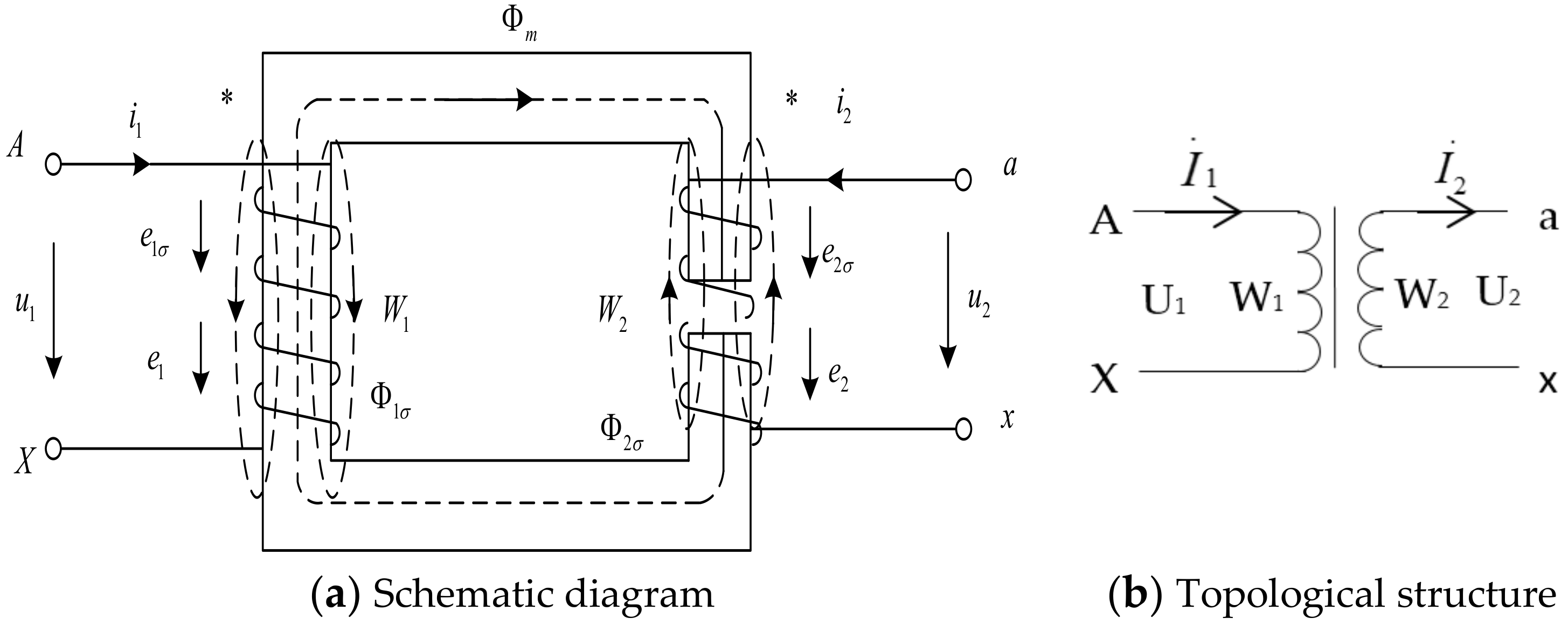
According to the topological structure and principle of PDFT, it is known that the thyristor is connected to the secondary reactance winding of the electromagnetic coupling reactor. Normally, the thyristor will generate a small amount of third, fifth, and seventh harmonic currents when it is under phase-shifting control. The magnitudes of these harmonic currents are closely related to the trigger angle α of thyristor [29]. 
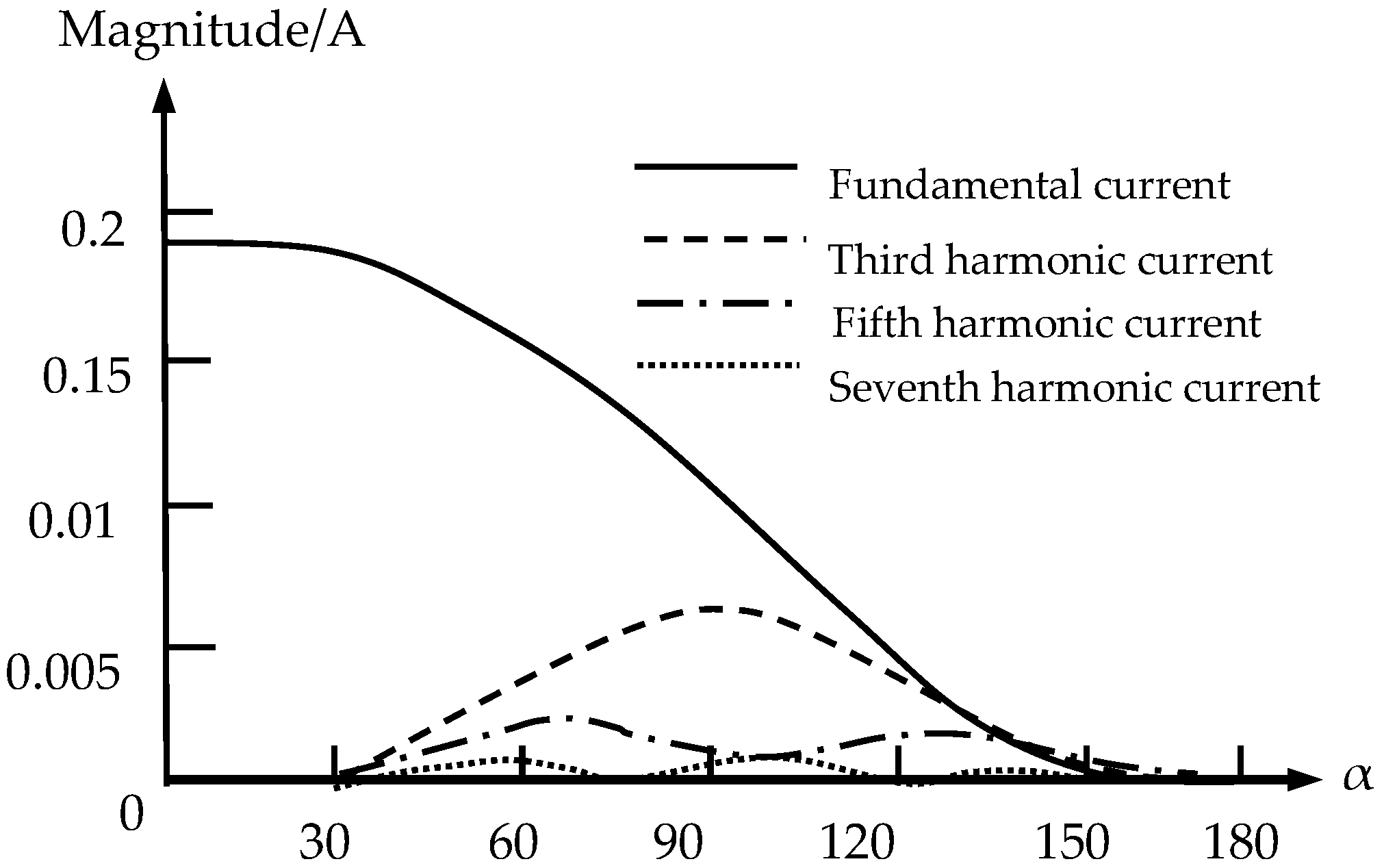
Figure 6 shows the curve of the fundamental current and harmonic current in the secondary winding of electromagnetic coupling reactor changing with trigger angle.
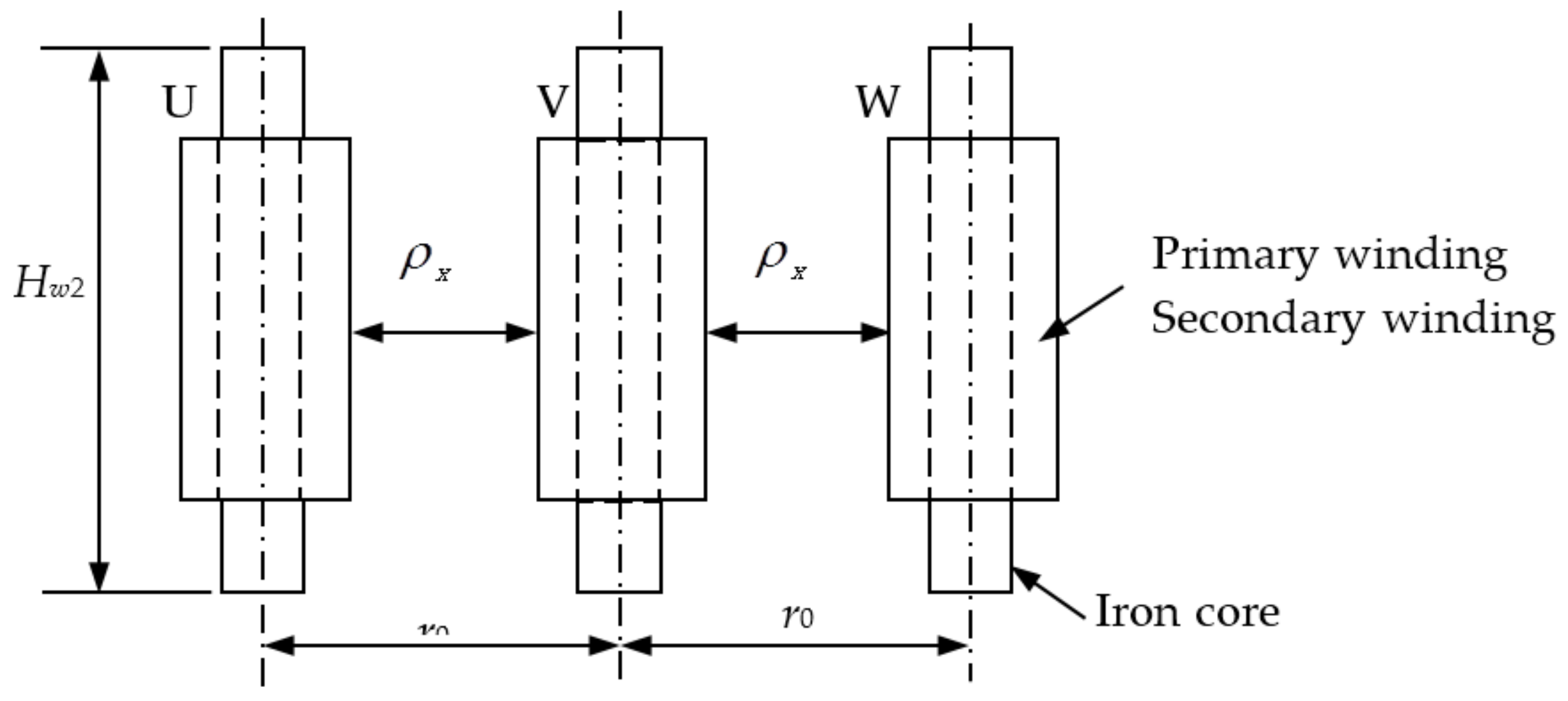
As the ratio of turns K of the primary winding of electromagnetic coupling reactor to the secondary winding is less than 1, according to relevant theories of electromagnetic transform, the fifth and seventh harmonic currents in primary winding are 1/N of those in secondary winding, and therefore, the fifth and seventh harmonic pollution caused by electromagnetic coupling reactor should not be ignored when K is large.
The above analysis shows that there are two ways to improve the performance of electromagnetic coupling reactor: (1) Replacing the electromagnetic coupling reactor with a double-reactor one in which a fixed reactor with an electromagnetic coupling reactor in a series of connection. (2) Increasing the turns ratio K of the primary winding of electromagnetic coupling reactor to the secondary winding. Then the harmonic current in primary winding induced by the harmonic current in secondary winding can be effectively reduced.
Therefore, to improve the performance of electromagnetic coupling reactor, two sets of electromagnetic coupling reactors designed by the above two methods were prepared. A field test using the prototype of PDTF was performed in the low-voltage distribution system of a cement plant.
Test Three: A fixed reactor and an electromagnetic coupling reactor in series were connected with PDTF to observe the filtering performance of PDTF.
The main circuit of PDTF after connection with fixed reactor is shown in Figure 7.
In Figure 7, La refers to the fixed reactor whose inductance is approximately 0.168 mH, and KL is the electromagnetic coupling reactor whose primary impedance winding has an inductance of 1.8 mH, approximately.
To study the effects of reactor’s structure on filtering performances of PDTF, two tests were conducted respectively using the single-reactor structure (KL) and double-reactor structure (KL + La). In the two cases, the capacitance across the filter capacitor was set at 40 Kvar. Considering that the resonance point of PDTF might shift when the inductance of reactor increased, two more tests were performed when the capacitances across the filter capacitor were 30 kVar and 35 kVar. The results of Test Three under four conditions are listed in Table 3.
The analytical results of Test 3 are as follows:
(1)
It is shown in 
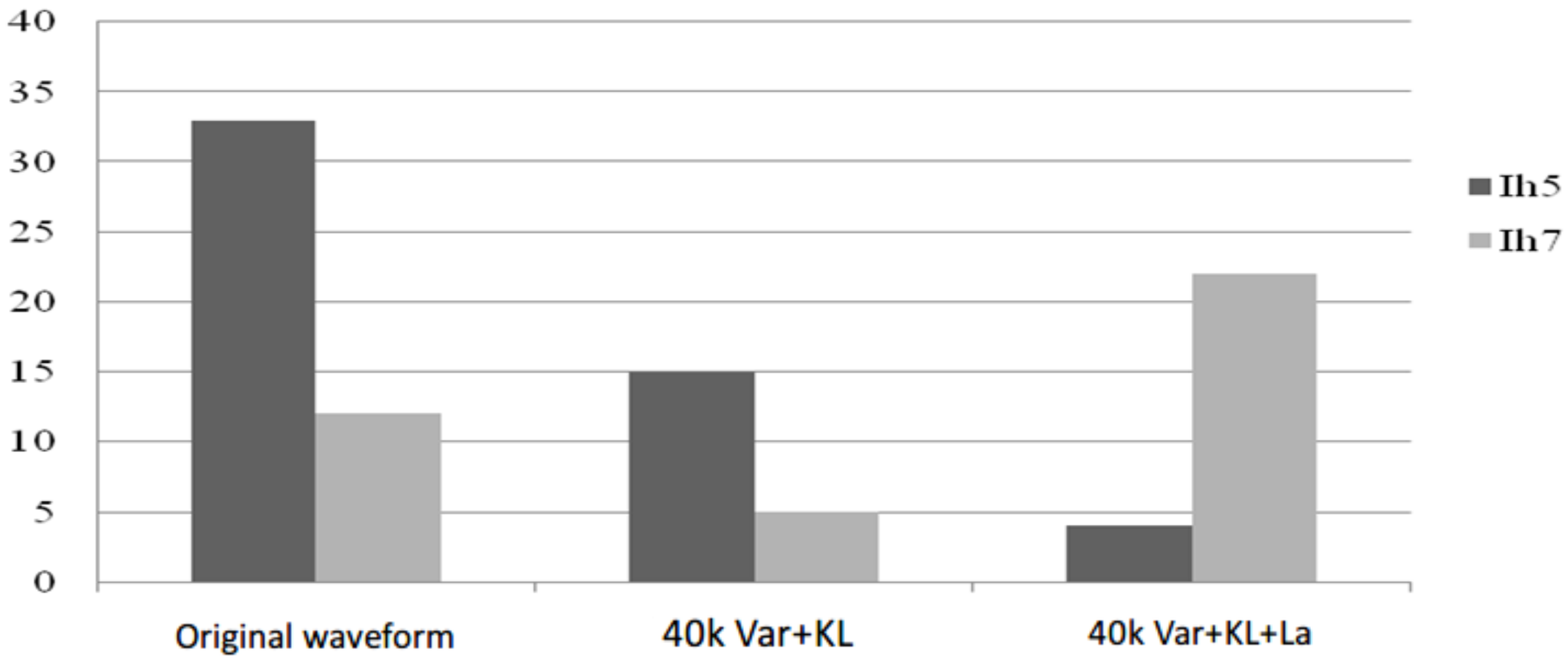
Figure 8 that under the same capacitance (40 kVar), by using the double-reactor structure (where an electromagnetic coupling reactor KL and a fixed reactor La are in series connection), the fifth harmonic current is reduced to 4 A from 15 A (single-reactor structure). Most of the fifth harmonic currents are filtered out (33 A before filtering). The control signal declines from 9900 to 5700 after using fixed reactor La. Thus, conclusions can be drawn that, under the same capacitance across the filter capacitor, the equivalent inductance of electromagnetic coupling reactor will reduce after connection with fixed reactor. When the control signals are 9900 and 5700 respectively, the corresponding thyristor trigger angles are 69° and 116°. As shown in Figure 6, when the thyristor trigger angle α is 116°, the seventh harmonic current generated by the secondary winding of electromagnetic coupling reactor reaches the wave crest. This indicates that the seventh harmonic current in system after connection with fixed La is larger than that before filtering.
(2)
As shown in Figure 9, after using the fixed reactor La, when the capacitance are 30 kVar and 35 kVar, the fifth harmonic current and seventh harmonic current in system are close (about 60% lower). When the capacitance across the filter capacitor is 40 kVar, the fifth harmonic current is reduced to 4 A. When the capacitances across the filter capacitor are 30 kVar, 35 kVar, and 40 kVarM, respectively, the corresponding control signals are 9050, 10,200, and 5700, with the corresponding thyristor trigger angles 78°, 65°, and 116°. It can be known from the curve which shows the correlation between the inductance of electromagnetic coupling reactor and the thyristor trigger angle α that, when the trigger angle α < 90°, the electromagnetic coupling reactor has the poor adjustability and its equivalent inductance is small. It not only verifies the conclusions in Section 4.2 (a moderate increase in capacitance of filter capacitor can help improve the filtering performance when the requirements for tuning has been met), but also indicates that the regulation performance of electromagnetic coupling reactor has been improved after using the fixed reactor La.
Test Four: The turns ratio of the primary winding of electromagnetic coupling reactor to the secondary winding was increased to observe the filtering performance of PDTF.
Due to the limited test conditions, the use of copper wire in the electromagnetic coupling reactor winding reactance winding coil is to increase the inductance. In this test, a double-reactor PDTF (the same as the one in Test Three) was used. An qualistar electrical network power and quality analyser (Chauvin Arnoux Metrix, Paris, France) was used to measure the inductance of primary winding of electromagnetic coupling reactor with additional cooper wire windings. The number of coils represents the additional turns of primary winding of ECRC.
The inductance of reactor of PDTF increases significantly due to the double-reactor structure and the additional turns of the primary winding of electromagnetic coupling reactor. For that reason, the capacitance across the filter capacitor should be changed. According to the calculation results, the capacitance ranges within 20~25 kVar approximately. Thus, the capacitance across the filter capacitor was set at 20 kVar and 25 kVar for further study. The main parameters of the system measured before and after by using filters are listed in 
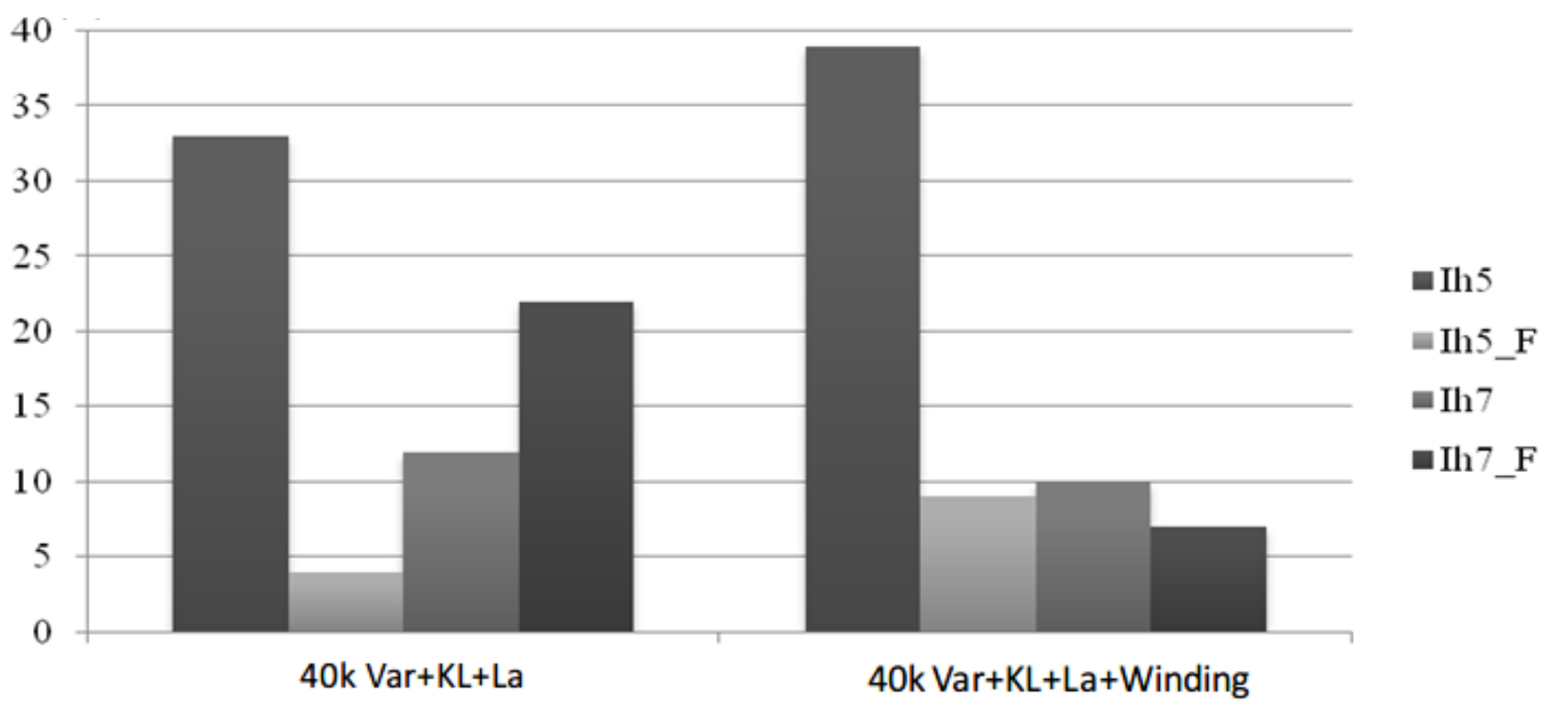
Table 4. It can be seen that after the passive dynamic tuning filter is put into the system, the 5th and 7th harmonic currents drop greatly in the system, with the 5th harmonic filter in the capacity of 25 kVar the effect being as high as 80% or more.
According to Table 4, in a series of connection of the same fixed reactor La, the reactor with additional turns of coil has a better filtering performance; that is because the reactor not only filters out the fifth harmonic current, but also inhibits the seventh harmonic current. The reactor without increasing the turns of coil achieves a good filtering performance of fifth harmonic, yet the seventh harmonic current increases slightly after filtering. Figure 10 shows the comparison of the performances in filtering fifth harmonic current under different conditions.
The results of Test Four show that by increasing the turns ratio K of the primary winding of electromagnetic coupling reactor to the secondary winding, the overall filtering performance of PDTF can be improved, and the higher-order harmonic current caused by the electromagnetic coupling reactor can be greatly reduced.
According to the relevant conclusions of the experimental research, the following three methods can be used to obtain the optimal design of the structure of the electromagnetic coupling reactor:
(1)
Reactors with passive reactance tuning filters can be formed by using fixed reactors in series with the dual reactor structure of the electromagnetic coupling reactor to improve the regulation performance of the electromagnetic coupling reactor and reduce the manufacturing cost of the electromagnetic coupling reactor.
(2)
It is possible to properly increase the turns ratio k of the primary reactance winding and the secondary reactance winding of the electromagnetic coupling reactor to reduce the higher harmonic current by the electromagnetic coupling reactor itself.
(3)
The electromagnetic coupling reactor can be designed to be multi-tapped to facilitate passive tuning of the passive tuning filter.

4.4. Field Test

In order to further verify the above conclusion, a prototype of passive dynamic tuning filter was used to carry out an on-site experimental research on the distribution room of Jiangnan Cement Plant. The main power distribution boxes of Jiangnan Cement Plant are shown in Figure 11.
The main electric devices of each distribution box are listed in Table 5. A 2500 kW distribution box whose incoming bus capacity is 1600 kW and incoming voltage is 6 kV was used. A powder separator with a 132 kW main harmonic load was used.
To further understand the harmonic current content of the power system, the power quality analyzer CA8335 is used to test the busbar input of the power grid. The current waveform of the power system is obtained, as shown in Figure 12. The current distortion of three phases in power grid is obvious, and the total distortion rates of harmonic current corresponding to phases A, B, and C are 4%, 12.3% and 13.6%, respectively.
The harmonic current contents in power distribution system are listed in 
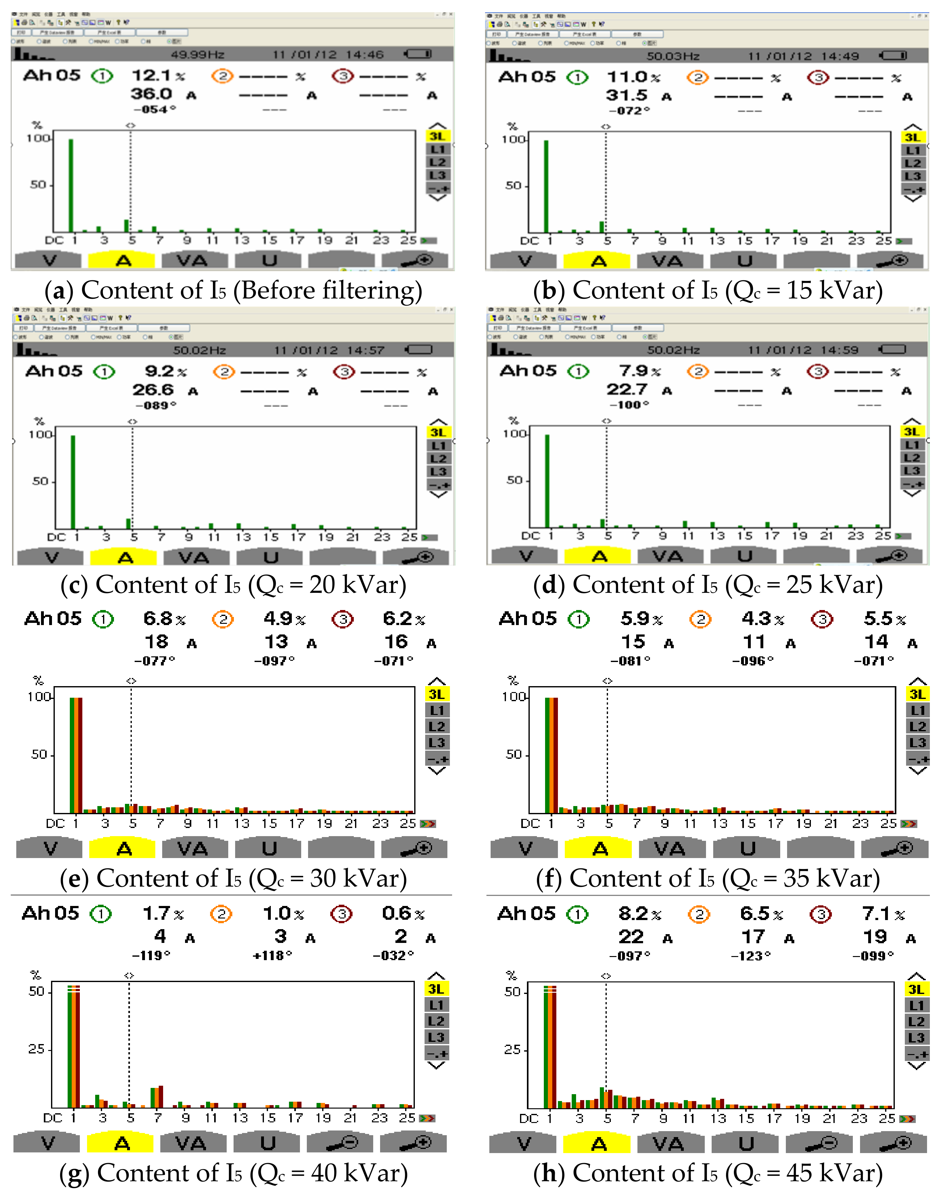
Table 6. There are lots of harmonic currents in the power distribution system, among which the fifth harmonic current content is the greatest and reaches a percentage of 13.4%, exceeding the national standard for the harmonic current content in public power network. Thus, in this test, the capacitances across the filter capacitor were set at 15 kVar, 20 kVar, 25 kVar, 30 kVar, 35 kVar, 40 kVar, and 45 kVar, and through the tuning of PDTF, the amount of fifth harmonic currents absorbed by PDTF were obtained.
The fifth harmonic current content without using PDTF is shown in a. Figure 13b–h show the harmonic current contents after using PDTFs whose capacitances are 15 kVar, 20 kVar, 25 kVar, 30 kVar, 35 kVar, 40 kVar, and 45 kVar, respectively.
The fifth harmonic current contents under different capacitances are listed in Table 7. As the tests were carried out during the running of cement plant, there is a slight fluctuation in current. The absorption current I5(x) refers to the difference between the fifth currents in power grid before and after filtering (the harmonic current before filtering is 37 A).
It can be seen from Table 7 that the passive harmonic filter has a different effect on the 5th harmonic current when the filters with different capacities are put into operation. When the capacitance is 40 kVar, the 5th harmonic current flows back to the grid bus. For the 4 A, the 5th harmonic current contents of 1.7% have a significant filtering effect. As shown in Table 7, the fifth harmonic current inhibited by PDTF varies under different capacitances. When the capacitance is 40 kVar, the fifth harmonic current returns power grid bus is 4 A, and the percentage of fifth harmonic current is 1.7%, an indication of a good filtering performance. The curve which shows the correlation between the filter capacitor’s capacitance Qc and the absorption current is shown in Figure 14.
In Figure 14, before the filter reaches the resonance point, the filtering performance will be improved with the increase of the capacitance. When the capacity of the capacitance is 40 kVar, the optimal filtering effect of the PDTF is the greatest.
Result analysis of the field test:
(1)
When the capacity of the filter capacitor is increased, the value of the control signal relatively increases and the reactance of the electromagnetic coupling reactor decreases, thereby ensuring that the passive dynamic tuning filter is always tuned to the resonant frequency. This shows that the passive dynamic tuning filter has some anti-detuning ability and dynamic tuning capability.
(2)
The capacity of the filter capacitor is closely related to the capacity of the passive dynamic tuning filter. As the capacity of the filter capacitor increases, the 5th harmonic current absorbed by the passive dynamic tuning filter becomes greater.
(3)
When the capacitance of filter capacitor increases, the increase amount of the control signal is small. It indicates that the electromagnetic coupling reactor mainly plays the role of “fine tuning and filtering.” That is, by regulating the electromagnetic coupling reactor, the passive dynamic tuning filter can be more precisely tuned to the resonant frequency.
In summary, the capacity of the filter capacitor determines the capacity of the passive dynamic tuning filter. Therefore, a reasonable selection of the capacity of the filter capacitor is crucial. Under normal circumstances, maintaining the same resonant frequency under the premise of properly increasing the capacity of the filter capacitor helps to improve the PDTF current absorption [30].

5. Conclusions

With the continuous development of electric power system, more and more nonlinear loads, such as rectifier loads and impulse loads, are increasingly being added to the modern electric power systems. This article presents a new setup in order to use the passive power filter with dynamic tunable for the harmonic filtering task. Based on the structure and mathematic model of electromagnetic coupling reactor, the design parameters of the device structures are provided, with the process structure achieved and optimized. By using the passive dynamic tunable filter, the performance of electromagnetic coupling reactor in the presence of non-linear filtering is analyzed, with a prototype of passive dynamic tuning filter used to carry out on-site experimental research on the distribution room of Jiangnan Cement Plant. The experimental results show that the capacity of the filter capacitor determines the harmonic absorption of the passive dynamic tuning filter, while the resonant frequency remains constant. By fine-tuning the electromagnetic coupling reactor, the filtering can be effectively solved, with filter capacitance due to changes in capacity caused by detuning and other issues. In general, under the premise of keeping the resonance frequency unchanged, properly increasing the capacity of the filter capacitor helps increase the absorption of this order harmonic current by the passive dynamic tuning filter. We believe that this research is promising if a sufficiently developed technological basis is available. In order to further eliminate the detuning caused by filter capacitor capacity variation, analysis and discussion should be made on the influences that the capacity of different filter capacitors exerts on the PDTF current absorption in future studies.

Author Contributions

Y.W. contributed to the conception of the study, the background research, method design and experimental results analysis, and wrote the manuscript; Y.Y. helped perform the analysis with constructive suggestions; J.C. provided an important suggestion about the framework of this paper and revised the manuscript. All authors read and approved the manuscript.

Acknowledgments

This work was supported by the National Support Program of China (#2015BAG20B05), the Zhejiang Province Natural Science Foundation of China (#LY14E070003), and the Independent Innovation Fund Project of Wuhan University of Technology (#2017-JL-002).

Conflicts of Interest

The authors declare no conflict of interest.

References

  1. Aiello, M.; Cataliotti, A.; Favuzza, S.; Graditi, G. Theoretical and experimental comparison of total harmonic distortion factors for the evaluation of harmonic and interharmonic pollution of grid-connected photovoltaic system. IEEE Trans. Power Deliv. 2006, 21, 1390–1397. [Google Scholar] [CrossRef]
  2. Wang, Y.F.; Yuan, Y.X. Development of a Soft Starter with Current-Limiting, Reactive Power Compensation and Harmonic Filtering. Appl. Mech. Mater. 2014, 462–463, 658–661. [Google Scholar] [CrossRef]
  3. Wang, Y.F.; Yuan, Y.X.; Chen, J.; Cheng, Q.J. A Dynamic Reactive Power Compensation Method of Super High-Power and High-Voltage Motor. Appl. Mech. Mater. 2014, 602–605, 2828–2831. [Google Scholar] [CrossRef]
  4. Wang, Y.; Yuan, Y. A dynamic reactive power compensation method for high-power and high-voltage electronic motors based on self-adaptive fuzzy PID control. In Proceedings of the 2016 IEEE Chinese Guidance, Navigation and Control Conference, Nanjing, China, 12–14 August 2016; IEEE: Piscataway, NJ, USA, 2017; pp. 10–15. [Google Scholar]
  5. Jou, H.L.; Wu, J.C.; Wu, K.D. Parallel operation of passive power filter and hybrid power filter for harmonic suppression. IEE Proc. Gener. Transm. Distrib. 2001, 148, 8–14. [Google Scholar] [CrossRef]
  6. He, N.; Xu, D.; Huang, L. The application of particle swarm optimization to passive and hybrid active power filter design. IEEE Trans. Ind. Electron. 2009, 56, 2841–2851. [Google Scholar] [CrossRef]
  7. Chen, J.; Tu, M.J.; Wang, Y.F.; Yuan, Y.X.; Cheng, Q.J. Study on High Capacity Reactive Power Fast Compensation Method. Power Capacit. React. Power Compens. 2017, 38, 1–6. [Google Scholar]
  8. Moran, L.A.; Dixon, J.W.; Wallace, R.R. A three-phase active power filter operating with fixed switching frequency for reactive power and current harmonic compensation. IEEE Trans. Ind. Electron. 1995, 42, 402–408. [Google Scholar] [CrossRef]
  9. Tang, Y.; Loh, P.C.; Wang, P.; Choo, F.H.; Gao, F.; Blaabjerg, F. Generalized design of high performance shunt active power filter with output LCL filter. IEEE Trans. Ind. Electron. 2012, 59, 1443–1452. [Google Scholar] [CrossRef]
  10. Asiminoael, L.; Blaabjerg, F.; Hansen, S. Detection is key-Harmonic detection methods for active power filter applications. IEEE Ind. Appl. Mag. 2007, 13, 22–33. [Google Scholar] [CrossRef]
  11. Kale, M.; Ozdemir, E. An adaptive hysteresis band current controller for shunt active power filter. Electr. Power Syst. Res. 2005, 73, 113–119. [Google Scholar] [CrossRef]
  12. Othman, A.; Gabbar, H. Enhanced Microgrid Dynamic Performance Using a Modulated Power Filter Based on Enhanced Bacterial Foraging Optimization. Energies 2017, 10, 776. [Google Scholar] [CrossRef]
  13. Marzband, M.; Azarinejadian, F.; Savaghebi, M.; Pouresmaeil, E.; Guerrero, J.M.; Lightbody, G. Smart transactive energy framework in grid-connected multiple home microgrids under independent and coalition operations. Renew. Energy 2018, 126, 95–106. [Google Scholar] [CrossRef]
  14. Marzband, M.; Fouladfar, M.H.; Akorede, M.F.; Lightbody, G.; Pouresmaeil, E. Framework for smart transactive energy in home-microgrids considering coalition formation and demand side management. Sustain. Cities Soc. 2018, 40, 136–154. [Google Scholar] [CrossRef]
  15. Valinejad, J.; Marzband, M.; Akorede, M.F.; Barforoshi, T.; Jovanović, M. Generation expansion planning in electricity market considering uncertainty in load demand and presence of strategic GENCOs. Electr. Power Syst. Res. 2017, 152, 92–104. [Google Scholar] [CrossRef]
  16. Beres, R.N.; Wang, X.; Liserre, M.; Blaabjerg, F.; Bak, C.L. A Review of Passive Power Filters for Three-Phase Grid-Connected Voltage-Source Converters. IEEE J. Emerg. Sel. Top. Power Electron. 2017, 4, 54–69. [Google Scholar] [CrossRef]
  17. Xue, Y.; Ju, Z.; Xiang, K.; Chen, J.; Liu, H. Multiple sensors based hand motion recognition using adaptive directed acyclic graph. Appl. Sci. 2017, 7, 358. [Google Scholar] [CrossRef]
  18. Leite, J.C.; Abril, I.P.; de Lima Tostes, M.E.; De Oliveira, R.C. Multi-objective optimization of passive filters in industrial power systems. Electr. Eng. 2017, 99, 387–395. [Google Scholar] [CrossRef]
  19. Li, Y.; Luo, L.; Rehtanz, C.; Wang, C.; Ruberg, S. Simulation of the electromagnetic response characteristic of an inductively filtered HVDC converter transformer using field-circuit coupling. IEEE Trans. Ind. Electron. 2012, 59, 4020–4031. [Google Scholar] [CrossRef]
  20. Szcześniak, P.; Kaniewski, J. Hybrid transformer with matrix converter. IEEE Trans. Power Deliv. 2016, 31, 1388–1396. [Google Scholar] [CrossRef]
  21. Kaniewski, J.; Fedyczak, Z.; Benysek, G. AC voltage sag/swell compensator based on three-phase hybrid transformer with buck-boost matrix-reactance chopper. IEEE Trans. Ind. Electron. 2014, 61, 3835–3846. [Google Scholar] [CrossRef]
  22. Xu, J.; Luo, L.; Li, L.; Li, Y.; Liu, F. Principle and Connection Scheme of Self-Coupled Compensating and Suppressing Harmonic Converter Transformers. Trans. China Electrotech. Soc. 2006, 9, 008. [Google Scholar]
  23. Oruganti, V.S.R.V.; Bubshait, A.S.; Simões, M.G. Real-time control of hybrid active power filter using conservative power theory in industrial power system. IET Power Electron. 2017, 10, 196–207. [Google Scholar] [CrossRef]
  24. Shivaie, M.; Salemnia, A.; Ameli, M.T. Optimal multi-objective placement and sizing of passive and active power filters by a fuzzy-improved harmony search algorithm. Int. Trans. Electr. Energy Syst. 2015, 25, 520–546. [Google Scholar] [CrossRef]
  25. Tian, M.; Li, J.; Shi, P.; Guo, Y. A Novel Quickness Improvement Method of a Magnetic-Valve Controllable Reactor. IEEE Trans. Appl. Supercond. 2016, 26, 1–5. [Google Scholar] [CrossRef]
  26. Marzband, M.; Parhizi, N.; Savaghebi, M.; Guerrero, J.M. Distributed smart decision-making for a multimicrogrid system based on a hierarchical interactive architecture. IEEE Trans. Energy Convers. 2016, 31, 637–648. [Google Scholar] [CrossRef]
  27. Marzband, M.; Sumper, A.; Domínguez-García, J.L.; Gumara-Ferret, R. Experimental validation of a real time energy management system for microgrids in islanded mode using a local day-ahead electricity market and MINLP. Energy Convers. Manag. 2013, 76, 314–322. [Google Scholar] [CrossRef]
  28. Li, D.; Zhu, Z.Q.; Qin, Y. A Novel Variable Reactor and Its Application to Shunt Power Quality Controller. IEEE Trans. Power Electron. 2016, 31, 4148–4158. [Google Scholar] [CrossRef]
  29. Ye, B.L.; Wu, W.; Gao, H.; Lu, Y.; Cao, Q.; Zhu, L. Stochastic Model Predictive Control for Urban Traffic Networks. Appl. Sci. 2017, 7, 588. [Google Scholar] [CrossRef]
  30. Yuan, J.; Zhou, J.; Yu, C.; Wang, Y.; Chen, B.; Song, M.; Hu, N.; Wang, J.; Zheng, H. Study on Harmonics Characteristics of Magnetic-Valve Controllable Reactor Based on the Finite Element Method. Magn. IEEE Trans. 2015, 51, 1–4. [Google Scholar] [CrossRef]
Figure 1. Schematic diagram and topological structure of electromagnetic coupling reactance converter.
Energies 11 01647 g001
Figure 2. Structure of electromagnetic coupling reactor.
Energies 11 01647 g002
Figure 3. Curve of impedance modulus | Z a | varying with control angle α of thyristor.
Energies 11 01647 g003
Figure 4. Diagram of the insulation radius between the center lines of iron cores and the window height of iron core.
Energies 11 01647 g004
Figure 5. Test platform for passive dynamic tunable filter.
Energies 11 01647 g005
Figure 6. Curves of fundamental current and harmonic current.
Energies 11 01647 g006
Figure 7. Diagram of main circuit of PDTF after connection with fix reactor.
Energies 11 01647 g007
Figure 8. Harmonic current contents in power grid before and after using fixed reactor La.
Energies 11 01647 g008
Figure 9. Harmonic current contents under different capacitances.
Energies 11 01647 g009
Figure 10. Comparison of performances in filtering fifth harmonic current
Energies 11 01647 g010
Figure 11. Structural drawing of the system of power distribution box.
Energies 11 01647 g011
Figure 12. Current waveforms in power grid.
Energies 11 01647 g012
Figure 13. Fifth harmonic current contents.
Energies 11 01647 g013
Figure 14. Filtering performance under different capacitances.
Energies 11 01647 g014
Table 1. Records of Test One.
Serial NumberCapacitance/kVarControl SignalIh5/AIf5/AIs5/A
12052007.075.21.81
220530010.65.844.9
320530012.736.056.4
420530017.686.4910.05
Table 2. Records of Test Two.
Serial NumberCapacitance/kVarControl SignalIh5/AIf5/AIs5/A
1155300106.65
2205250109.251.85
Table 3. Results of Test Three under four conditions.
Serial No.1234
Contents
UVWUVWUVWUVW
I1/A276272270276272270276272270276272270
Ih5/A151114432201717161113
Ih7/A578222120566532
Control Signal90005700905010200
Capacitance/Var40403035
ReactorKLKL + La
Table 4. Main parameters of system before or after filtering.
Measured ParametersUVWUVW
I1/A320314311320314311
Ih5/A (before filtering)393637393637
Ih5/A (after filtering)1097944
Ih7/A (before filtering)101313101313
Ih7/A (after filtering)12109737
Control Signal96009850
Capacitance/kVar2025
Table 5. List of electric devices of distribution box.
No.Main Electric Devices
AT01Incoming line of power supply
AT02Powder separator, constant feeder
AT03Chute fan, filter incoming cubicle
AT04Plenum pulse dust collector, single-chamber pump
AT05Discharging machine, spiral reamer, motor fluid resistance starter
AT06Electric louver valve, sampler, illumination, maintenance power supply, PLC power supply
Table 6. Harmonic current contents in power distribution system.
Test ContentsPhase APhase BPhase C
I1/A276272270
I5/A363333
I7/A12146
I11/A7105
I13/A563
ФVA (°)+40°+37°+39°
Table 7. Harmonic current contents under different capacitances.
Capacitance of Filter Qc/kVarControl Signal UkBus Current I5/AAbsorption Current I5(x)/A
15930031.55.5
20930026.610.4
25930022.714.3
3099001819
3599001522
409650433
4599502215

