Article

Industrial-Scale Experimental Study on the Thermal Oxidation of Ventilation Air Methane and the Heat Recovery in a Multibed Thermal Flow-Reversal Reactor

1
Key Laboratory of Low-grade Energy Utilization Technologies and Systems of Ministry of Education, College of Power Engineering, Chongqing University, Chongqing 400044, China
2
China Coal Technology and Engineering Group Chongqing Research Institute, Chongqing 400037, China
*
Author to whom correspondence should be addressed.
Energies 2018, 11(6), 1578; https://doi.org/10.3390/en11061578
Submission received: 28 May 2018 / Revised: 11 June 2018 / Accepted: 13 June 2018 / Published: 15 June 2018

Abstract

:
In the present work, an industrial-scale experiment on ventilation air methane (VAM) utilization by a multibed thermal flow-reversal reactor (TFRR) is conducted in China. The influence of the inlet flow rate, feed methane concentration, and cycle time on the temperature distribution of the bed and heat recovery efficiency are investigated. The methane conversion in the studied cases exceeds 97%. The results show that the methane concentration during self-maintained operation of the TFRR without heat recovery should not be less than 0.22 vol % when the inlet flow rate is 103,000 Nm3/h and the cycle time is 300 s. As the inlet flow rate decreases, the lower concentration limit of automatic thermal maintenance increases. The peak temperature of the bed approaches the inlet side as the feed methane concentration increases and the cycle time decreases. The heat recovery efficiency increases linearly with increasing inlet flow rate, rises parabolically with an increasing feed methane concentration, and decreases weakly with increasing cycle time.

1. Introduction

Methane emissions are the second highest non-water greenhouse gas (GHG) emissions. The methane concentration in the atmosphere has risen by 151% during the last 250 years [1]. Coal mine methane (CMM) is a major source of anthropogenic methane emissions. To ensure mine safety, CMM is usually diluted by ventilation to degasify the air in the mine. Approximately 64% of CMM emissions come from ventilation air methane (VAM) [2]. The pure methane emissions from VAM during coal mining totaled 16.1 billion cubic meters in 2008 in China [3]. The capture and utilization of VAM represent a great challenge because of the large volume and low methane concentration, typically 0.3 vol % to 0.75 vol %, of VAM.
Utilization technologies of VAM can generally be divided into ancillary and principal uses [2,4,5,6,7,8,9]. For ancillary uses, VAM is used to replace ambient air in combustion processes to reduce the use of primary fuel. The requirement of local combustion equipment adjacent to mines limits the applicability of the technique. For principal uses, VAM is used as a primary fuel. Due to the low methane concentration in VAM, catalytic flow-reversal reactors (CFRRs) and thermal flow-reversal reactors (TFRRs) seem to be the most feasible solutions for VAM utilization.
To date, most investigations have focused on catalytic combustion in CFRRs. Mei et al. [10] investigated the influence of the temperature, methane concentration, inlet velocity, and catalyst on methane conversion by modeling the catalytic combustion in a monolith reactor. Marín et al. [11] experimentally determined the effects of the methane inlet concentration, gas flow rate, and switching time on the performance of a bench-scale CFRR. Wang et al. [12] performed experiments to investigate the effects of the initial temperature, space velocity, feed methane concentration, and cycle time on the catalytic combustion of VAM in a CFRR. Gosiewski [13] simulated the effect of heat recovery on the maximum temperature in a reverse-flow reactor with heat recovery. Marín et al. [14] performed 1-D simulations of CFRR performance with different heat recovery strategies, including the possibility of returning the cooled gases to the gas and extraction point (center or end, respectively). Wang et al. [15] reported experimental results from a pilot-scale CFRR with a spiral heat exchanger in the center of the reactor. The effects of various operating parameters and the heat transfer flux on periodic temperature fluctuations and the axial temperature profile were investigated. Fernández et al. [16,17] presented a novel reverse flow reactor with integrated water adsorption. Experiments showed that the adsorbent could eliminate catalyst inhibition by separating water from the inlet gas before reaching the catalyst.
Many studies have also been performed on thermal oxidation in TFRRs. Pawlaczyk and Gosiewski [18,19] presented an experimental kinetic study on the thermal combustion of lean methane-air mixtures and hypothesized that the combustion process in the monolith bed combined heterogeneous surface combustion and homogeneous combustion in the gas phase. Qi et al. [20] carried out 1-D numerical simulations of the thermal combustion of methane-air in a TFRR to investigate the effects of the inlet velocity and methane concentration. Lan and Li [21] presented a simulation study of a honeycomb ceramic channel without reaction to investigate the effects of the inlet flow rate, solid heat capacity, and switching time on thermal efficiency. Gosiewski et al. [22] performed experiments and 1-D simulations with a TFRR and confirmed that the temperature profiles in the reactor were not influenced by the heat capacity of the TFRR wall. Based on experimental and simulated results, Gosiewski et al. [23] revealed that a TFRR with a central cooling system was more prone to thermal asymmetry than a configuration consisting of hot gas withdrawal and heat recovery. Li et al. [24] conducted a demonstration project in China for VAM utilization by using a TFRR. Only when the methane concentration was higher than 0.6 vol % was the effective and economical operation with heat recovery for electricity generation possible.
Gosiewski and Pawlaczyk [25,26] compared the utilization of VAM by a TFRR and CFRR. For high VAM concentrations (above 0.4 vol %), TFRRs have proven to be the more inexpensive and reliable choice because it enables cost-effective heat recovery. Therefore, TFRRs are now frequently regarded as an attractive alternative for VAM utilization with good application prospects. However, industrial-scale experimental studies on the thermal oxidation of VAM in a TFRR have been rare. The automatic thermal maintenance performance and the effects of the main operating parameters on the heat recovery efficiency have not been clearly studied in previous research. In this work, an industrial experimental system was constructed to test the thermal oxidation performance of a multibed TFRR under different operating conditions. The effects of the inlet flow rate, feed methane concentration, and cycle time on the temperature distribution of the bed and heat recovery efficiency are analyzed.

2. Experimental Section

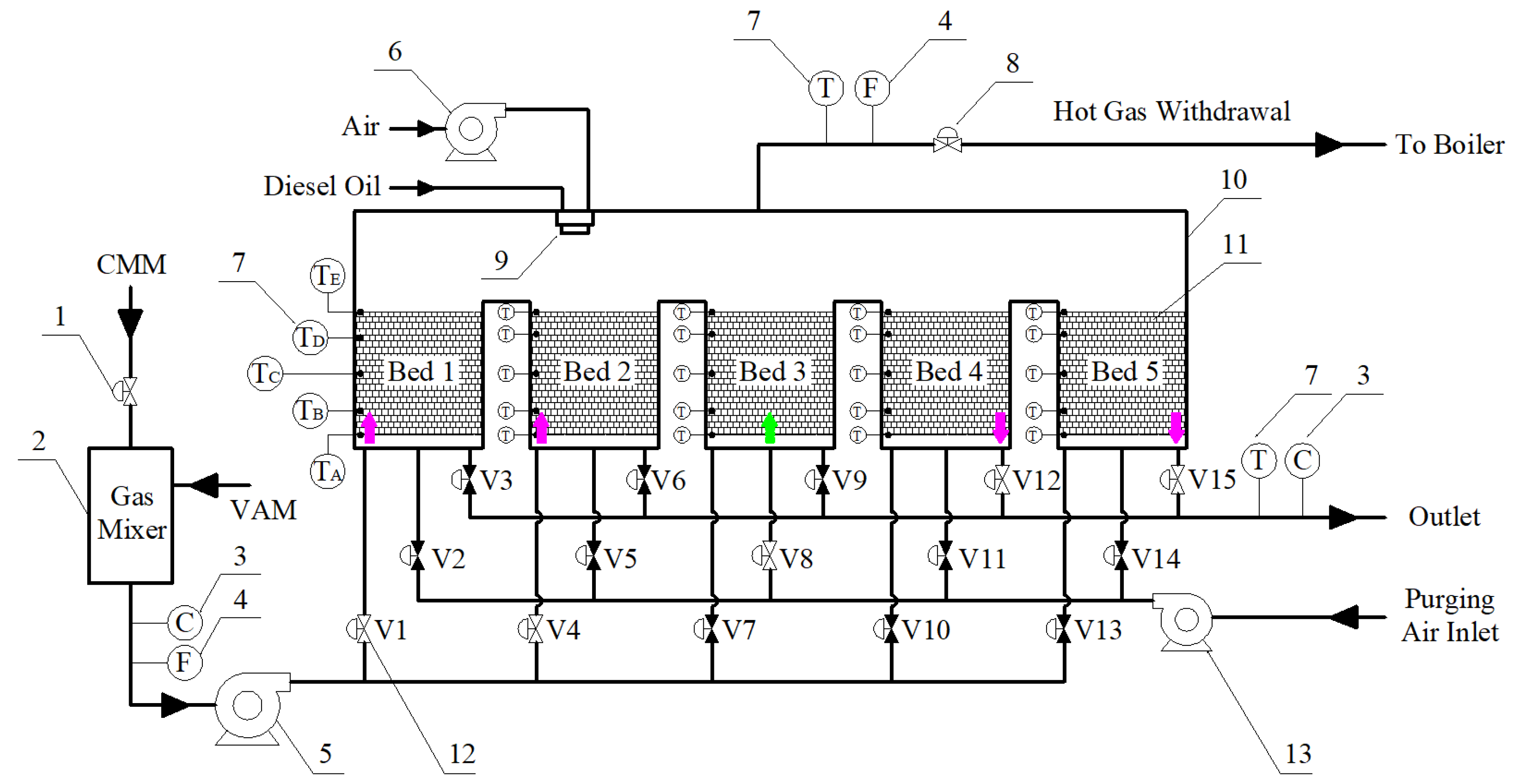
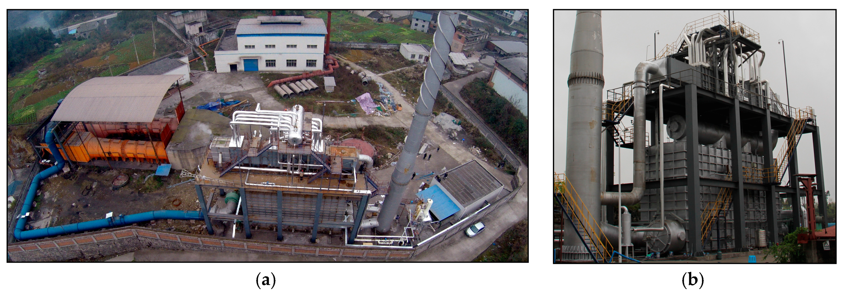
2.1. Experimental System

A simplified flow sheet of the industrial-scale VAM oxidation system is shown in Figure 1, and the photographs of the on-site project equipment are shown in Figure 2. The system consists of a gas mixer, multibed TFRR, fans, and programmable logic controller (PLC) system.
The multibed TFRR consists of five regenerator beds, a combustion chamber with a diesel burner, and switching valves. The regenerator beds are filled with honeycomb ceramics, which act as a heat exchanger. The individual regenerator beds are connected by combustion chamber. A diesel burner system is used to preheat the regenerator beds to the required start-up temperature. Each bed connects with an inlet valve, an outlet valve and a purging valve. Thermocouples, flow sensors, and methane concentration sensors are connected to the PLC system and monitor the temperatures of the beds and gas, the rates of the inlet and withdrawal flow, and the methane concentrations at the inlet and outlet, respectively.
VAM and CMM are mixed by a gas mixer to achieve a certain methane concentration. The methane concentrations of VAM and CMM are 0.3 vol % and 10 vol % respectively. The feed gas is forced by a fan and flows through the switching valves alternately controlled by a timer system. The gas flows into two of the regenerator beds and then through the hot beds from bottom to top and is preheated above the ignition temperature of methane. The reacted hot exhaust gas then flows through the cold beds from top to bottom, transmitting its heat to the beds. For heat recovery, part of the hot exhaust gas is extracted from the combustion chamber to a boiler. The withdrawal flow rate is controlled by a flow control valve.
The flow direction through the bed is changed alternately when the bed reaches the optimum heat storage point. Table 1 shows the valve-switching schedule for the multibed TFRR. As shown in Table 1, a full cycle consists of five processes. The valve switches follow the schedule controlled by the timer system. For example, in the process shown in Figure 1, the feed gas flows into beds 1 and 2, the exhaust gas is released from beds 4 and 5, and the purging air flows into bed 3. Beds 1 and 2 are in the heat-releasing state, beds 4 and 5 are in the heat-absorbing state, and bed 3 is in the purging state.

2.2. Experimental Conditions

The size of the multibed TFRR is 15 m (length) × 4.8 m (width) × 8 m (height). The rated capacity of the reactor is 100,000 Nm3/h. The size of one honeycomb ceramic block is 150 × 150 × 300 mm. Each regenerator bed has 6 layers of honeycomb ceramics. The honeycomb ceramics are composed of mullite and have a density of 2.0–2.6×10³ kg/m3, specific heat capacity of 900–1100 J/kg K, and thermal conductivity of 1.5–2.0 W/m K. The channel size is 3 × 3 mm, and the wall thickness is 0.7 mm. The void fraction of the honeycomb ceramics is 65%. The thickness of the insulation is 300 mm, with a density of 200 kg/m3. The conductivity of the insulation is 0.05 W/m K. The gas samples collected from the inlet and outlet were analyzed by gas chromatography and used to determine the methane conversion under each test condition. Table 2 summarizes the 13 sets of operating conditions and the results for the methane conversion (φCH4) and heat recovery efficiency (η) in the experiments, where Fin is the inlet gas flow rate, YCH4,in is the mole fraction of CH4 species at the inlet and tc is cycle time.

2.3. Energy Balance Analysis for the Multibed TFRR

The energy equation for the reactor is defined as follows:
Qgen = Qdraw + Qex + Qdisp
where Qgen is the heat generated by methane reaction, Qdraw is the heat recovery by hot gas withdrawal, Qex is the heat loss due to exhaust gas, and Qdisp is the heat dissipation.
Qgen = Fin × YCH4,in × φCH4 × hr0
where hr0 is the reaction heat of methane.
φCH4 = 1 − YCH4,out/YCH4,in
where YCH4,out is the mole fraction of CH4 species at the outlet.
Qdraw = Fdraw × (hg,drawhg,in)
where Fdraw is the withdrawal gas flow rate, hg,draw is the enthalpy of the withdrawal gas, and hg,in is the enthalpy of the inlet gas.
Qex = (FinFdraw) × (hg,outhg,in)
where hg,out is the enthalpy of the outlet gas.
The heat recovery efficiency evaluates the heat recovery performance of the reactor and is defined as follows:
η = Qdraw/Qgen × 100%
Importantly, the flow rates and enthalpies used in the above equations are averages of the values recorded during a full cycle.

3. Results and Discussion

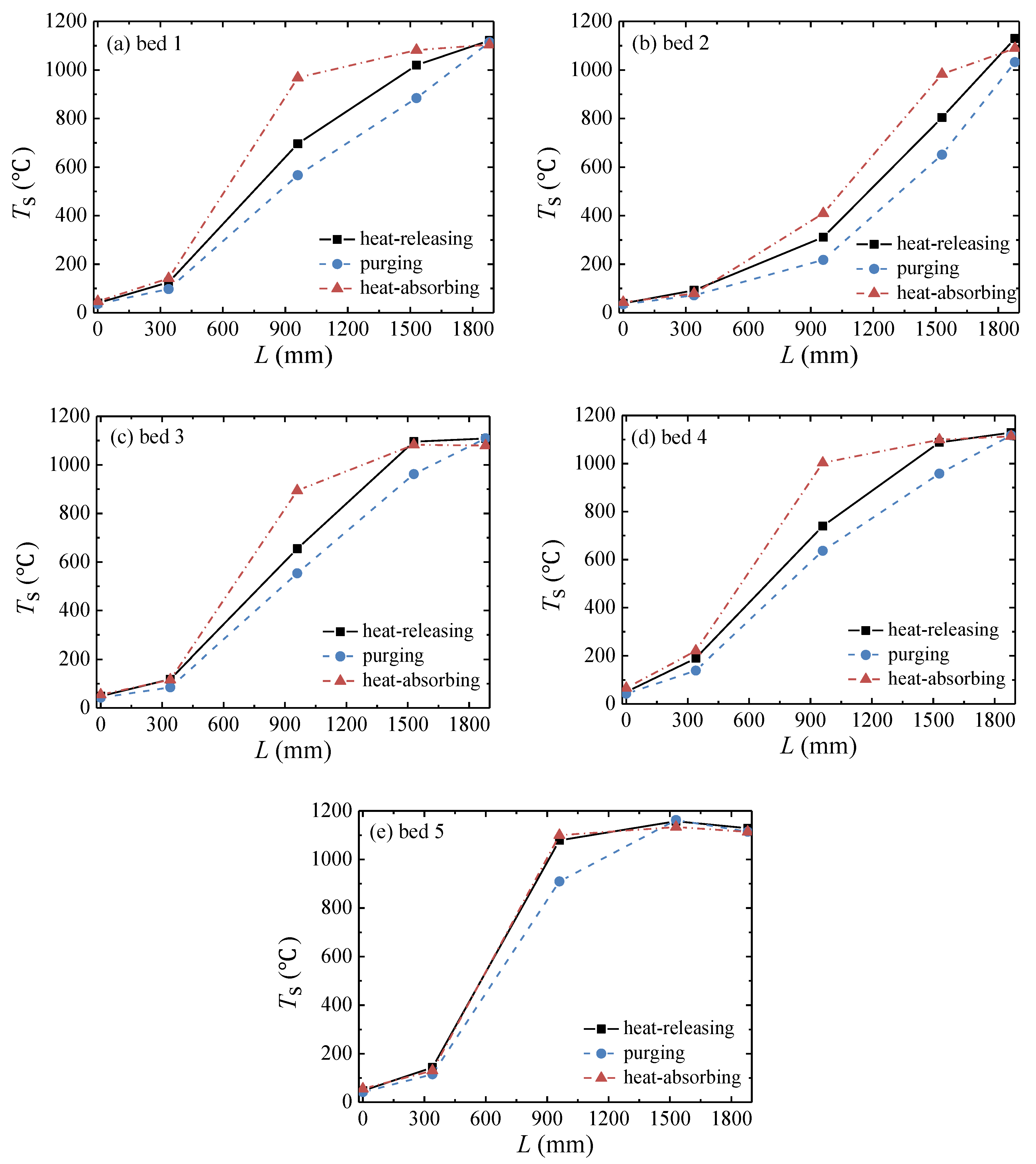
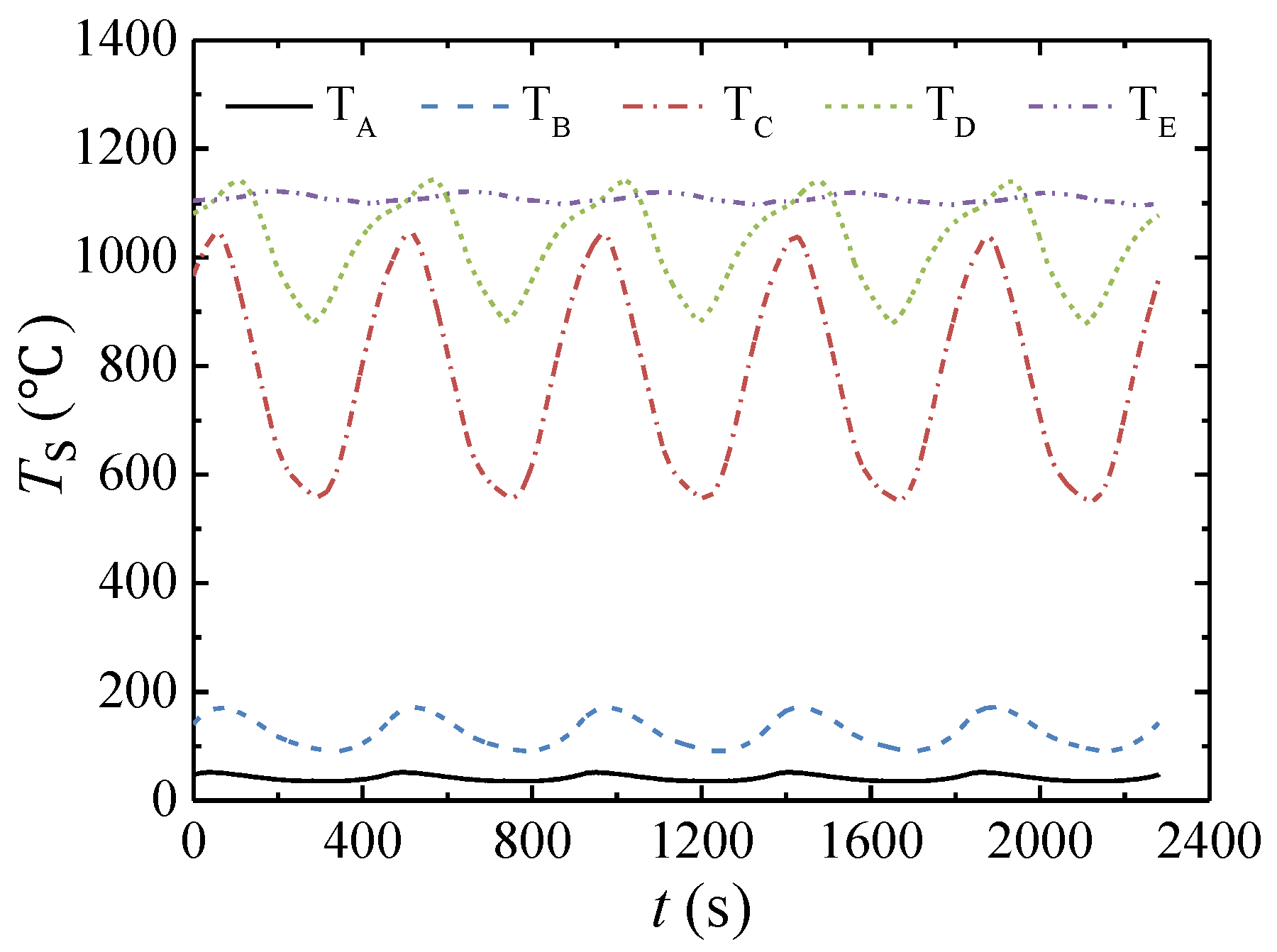
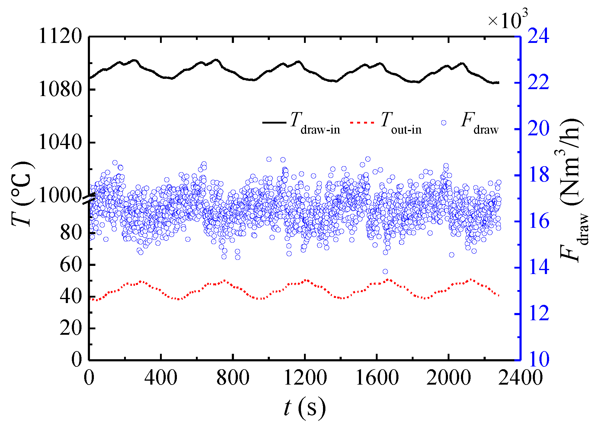
3.1. Performance of the Multibed TFRR

Figure 3 shows the fluctuation of the flow rate and methane concentration at the inlet during five full cycles. When a regenerator bed is transformed from a heat-absorbing state to a heat-releasing state, the outlet valve is switched from open to closed, and the inlet valve is switched from closed to open. When the two valves are simultaneously actuated, the gas flows directly from the inlet valve to the outlet valve, causing the gas flow rate to fluctuate significantly in a short period of time, as shown in Figure 3. The average gas flow rate for this case is 105,000 Nm3/h. The average inlet methane concentration is 0.94 vol %. The following data were obtained when the system was continuous and stable for 30 h.
Figure 4 shows the solid temperature (Ts) profile along the length (L) of the TFRR for the five honeycomb beds at the end of the heat-releasing, purging, and heat-absorbing stages. In the heat-releasing state, cold gas flows through a hot bed from bottom to top, and the bed temperature decreases. In the purging state, a small amount of clean air flows from bottom to top, and the bed temperature continues to decrease. In the heat-absorbing state, the reacted hot exhaust gas flows through a cold bed from top to bottom, and the bed temperature rises gradually. This temperature change pattern occurs in the five beds. However, the temperature profiles of the beds are different from one another. Therefore, the cycle steady state (CSS) is asymmetrical. The main cause of this phenomenon is that part of the hot gas is extracted from the combustion chamber, which affects the flow field and temperature distribution in the reactor.
Figure 5 shows the temperature fluctuation at the five monitoring points in bed 1 during five cycles. The time of maximum temperature at the five monitoring points in bed 1 is inconsistent. The time required to achieve the peak temperature after the bed enters the heat-releasing state at points A through E are 32 s, 59 s, 54 s, 106 s, and 183 s, respectively. The temperature fluctuations at points C and D, 494 °C and 267 °C, respectively, are larger than those at the other points. The peak temperature of bed 1 is achieved at point D; thus, methane oxidation occurs mainly in this section.
Due to the fluctuation of the inlet flow rate, the extracted gas flow rate fluctuates irregularly, as shown in Figure 6. The average flow rate of hot gas withdrawal is 16,550 Nm3/h, accounting for 18.84% of the inlet flow rate. The fluctuations in the withdrawal-inlet and outlet-inlet gas temperature differences (Tdraw-in and Tout-in ) are shown in Figure 6, with amplitudes of 17.9 °C and 13.7 °C, respectively. Under this working condition, the methane conversion is 99.1%, and the heat recovery efficiency is 72.7%.

3.2. Critical Cases Concerning Automatic Thermal Maintenance

The lower concentration limit (YCH4,min) of automatic thermal maintenance indicates the methane concentration at which supplemental energy is required to maintain the reactor temperature or at which energy in the feed gas is recoverable. This limit is an important parameter for equipment design.
Figure 7 shows the temperature distribution in bed 1 along the TFRR length at the end of the cycle for automatic thermal maintenance with different inlet flow rates. The highest temperatures in the bed for the four cases occur at point E. The maximum temperature of the bed increases with increasing flow.
The lower concentration limit and average outlet-inlet temperature difference (Tave,out-in) for self-maintained operation with different inlet flow rates are shown in Figure 8. As the flow rate increases, the outlet-inlet temperature difference rises sharply and then slowly increases, reflecting the coupling effect of the increases in flow rate and peak temperature of the bed. The lower concentration limit decreases with increasing flow rate. Figure 9 shows that the heat generated by the methane reaction and the heat loss of the exhaust gas increase linearly with the increase in flow rate. For automatic thermal maintenance, the heat recovery by hot gas withdrawal is zero. According to Equation (1), the heat dissipation is the difference between the heat generated by the methane reaction and the heat loss of exhaust gas. Under the four different flow rates, the heat dissipation is approximately the same. Therefore, with a low flow rate, a high methane concentration is required to fulfil the heat dissipation.

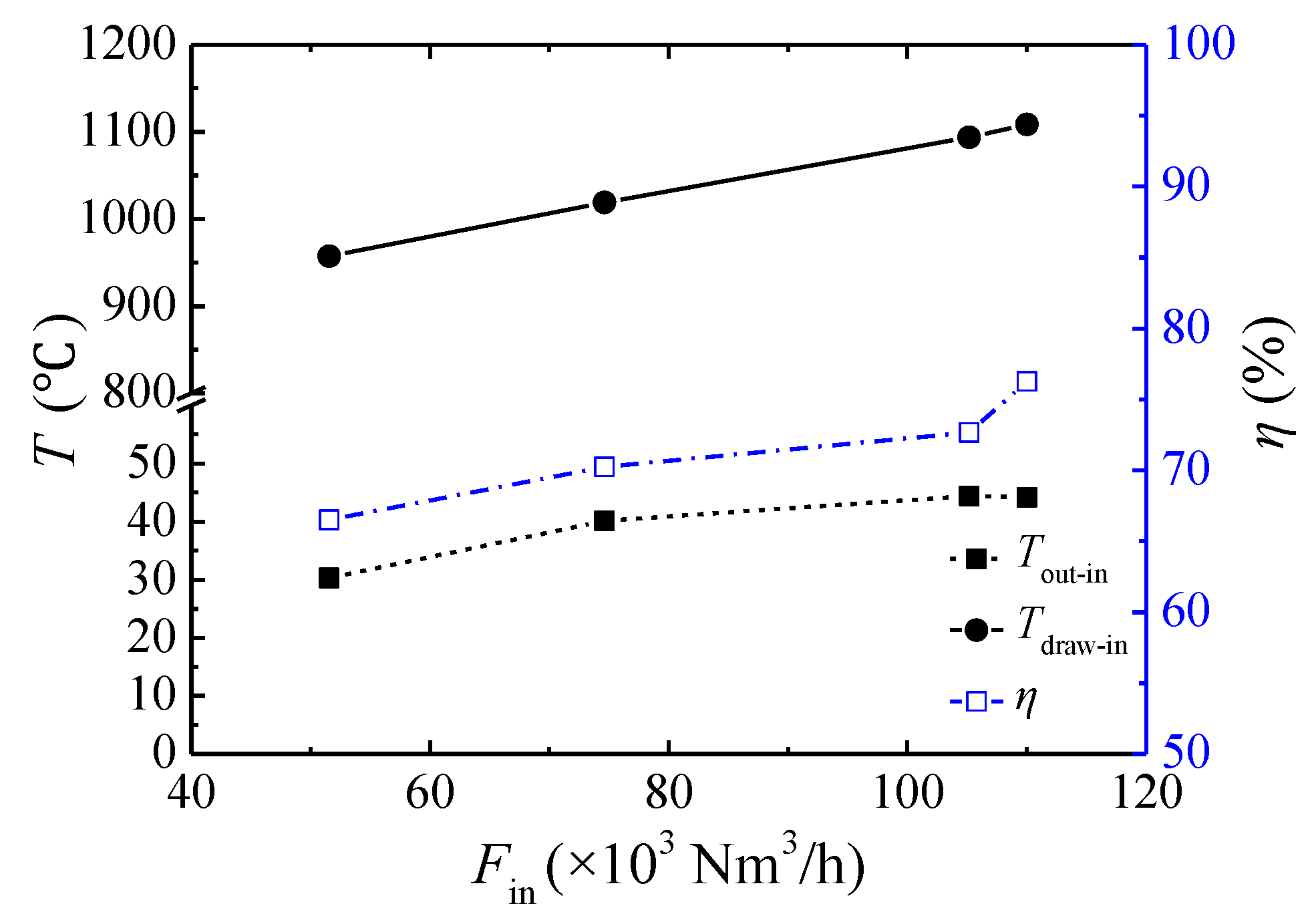
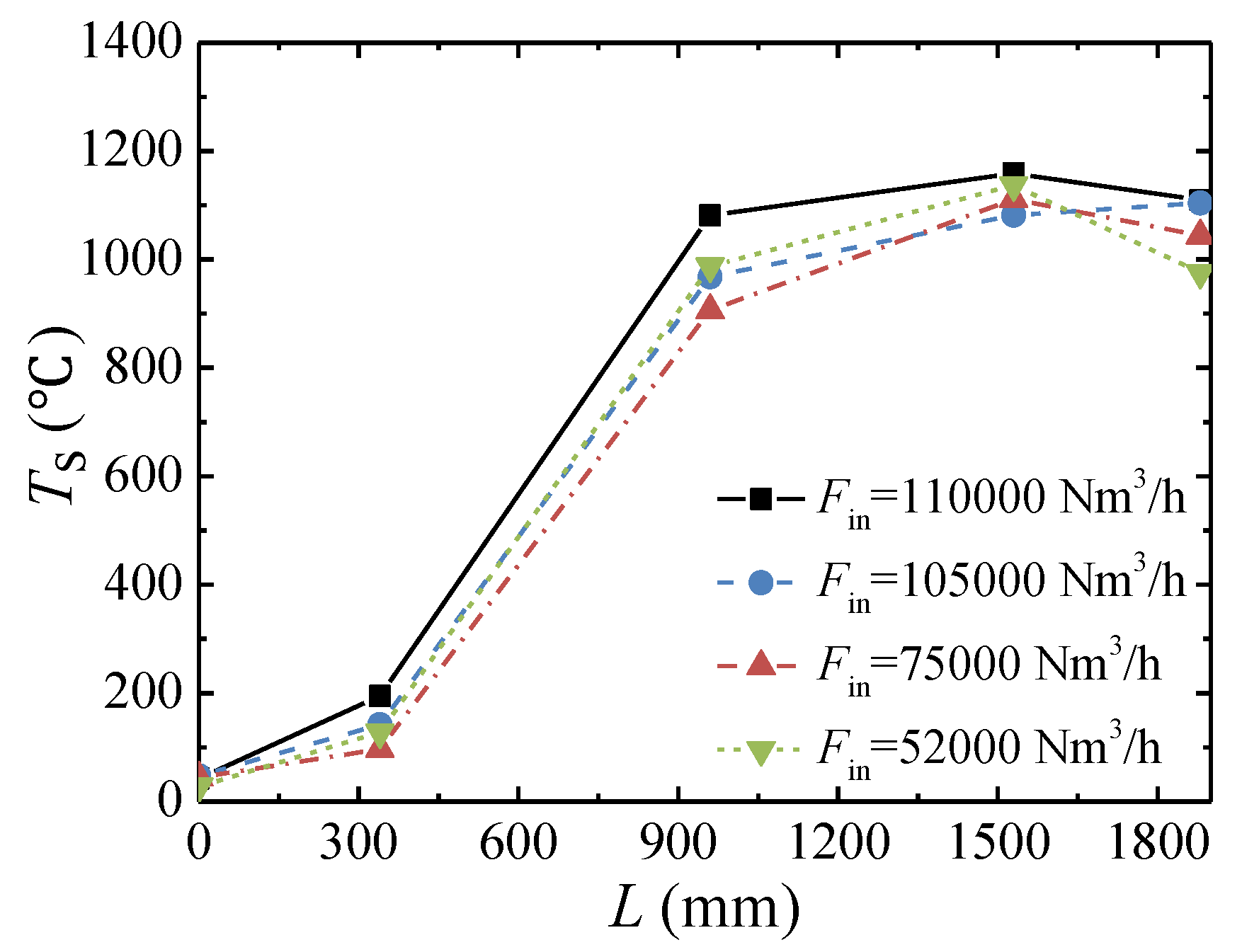
3.3. Effect of the Inlet Flow Rate

The solid temperature profile of bed 1 along the TFRR length under different inlet flow rates at the end of the heat-absorbing state at YCH4,in ≈ 1 vol % and tc = 450 s are shown in Figure 10. The highest bed temperature occurs at point D under all four flow rates. However, the maximum bed temperature is not significantly related to the flow rate.
As shown in Figure 11, the temperature difference between hot gas withdrawal flow and inlet gas increases linearly from 957 °C to 1109 °C when the inlet flow rate increases from 52,000 Nm3/h to 110,000 Nm3/h, respectively. As the inlet flow rate increases, the heat exchange between the solid and gas becomes high. However, the increase in heat flux does not match the increase in heat exchange, and the outlet-inlet temperature difference increases from 30 °C to 44 °C. Finally, the heat recovery efficiency increases from 66.5% to 76.3% with an increase in the inlet flow rate.

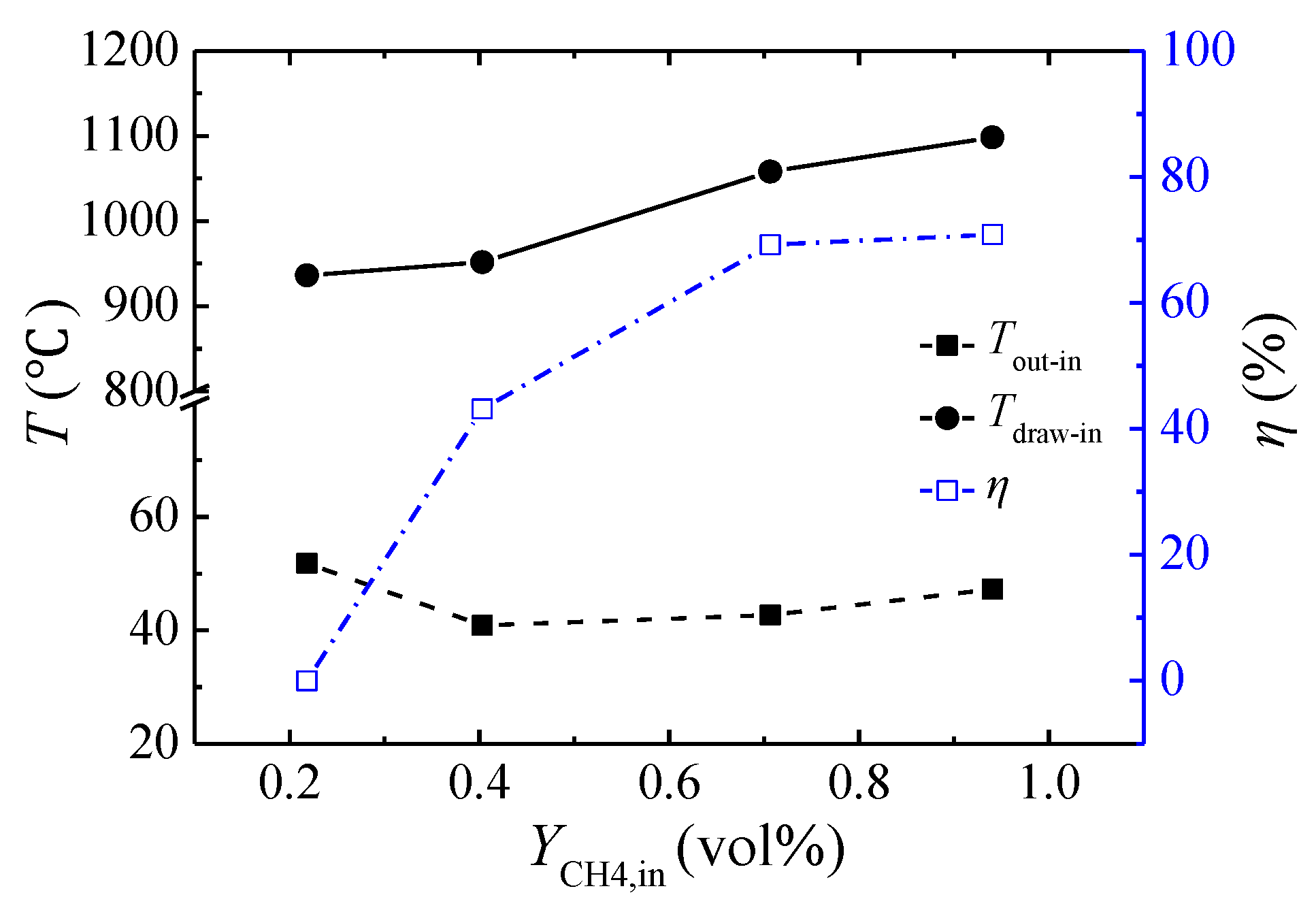
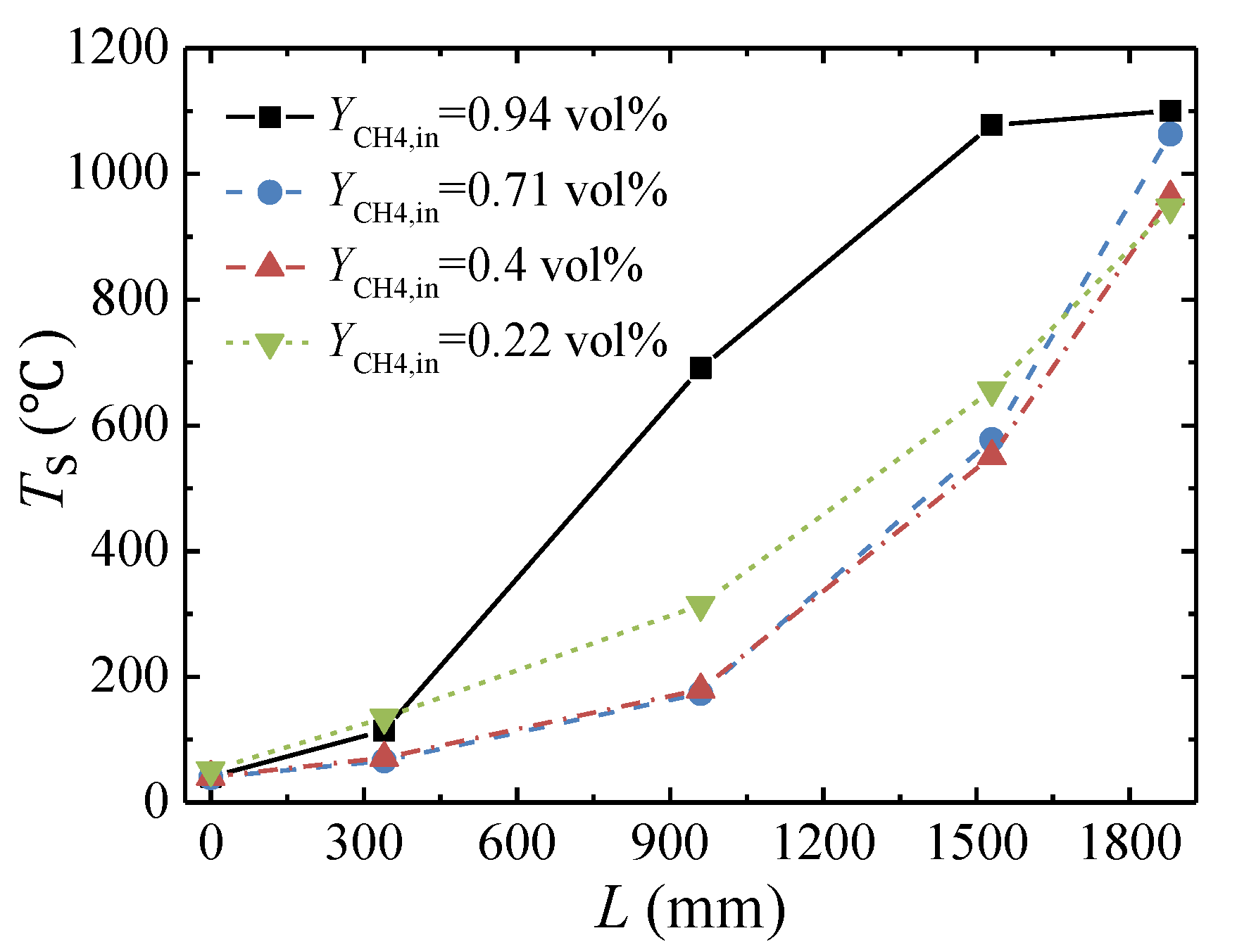
3.4. Effect of the Feed Methane Concentration

Figure 12 shows the solid temperature distribution in bed 1 at four methane concentrations when Fin ≈ 105,000 Nm3/h and tc = 300 s. The highest bed temperature occurs at point D for a methane concentration of 0.94 vol % but at point E for the other concentrations.
Figure 13 shows temperature difference between the hot gas withdrawal flow and inlet gas, outlet-inlet gas temperature difference, and heat recovery efficiency for different feed methane concentrations. As the methane concentration increases from 0.22 vol % to 0.94 vol %, the temperature difference between the hot gas withdrawal flow and the inlet gas increases from 936 °C to 1098 °C, respectively. The outlet-inlet temperature difference at a concentration of 0.22 vol % is higher than that at the other concentrations because no heat is recovered at this concentration. The heat recovery efficiency gradually increases from 0% to 70.8% with an increase in the feed methane concentration.

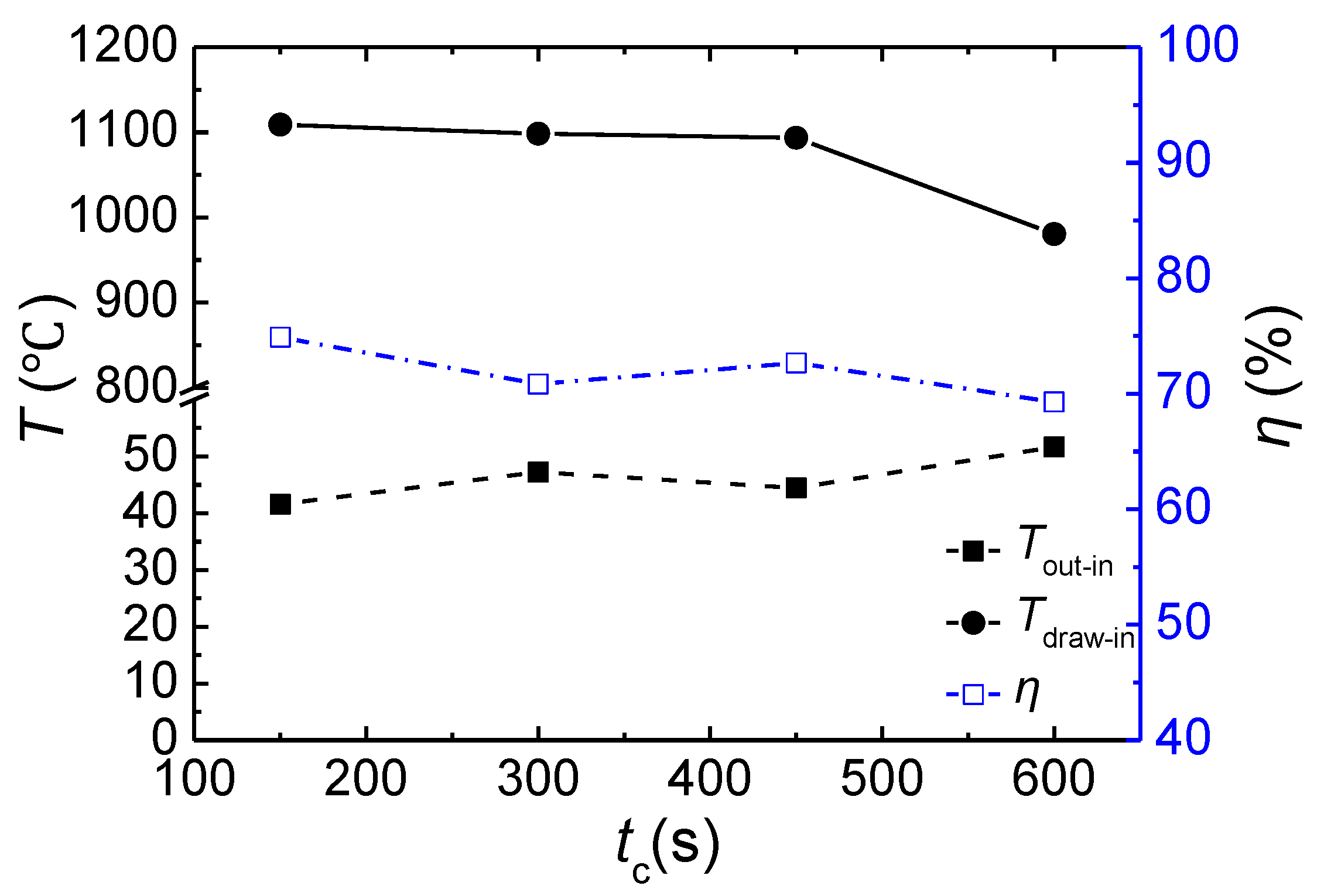
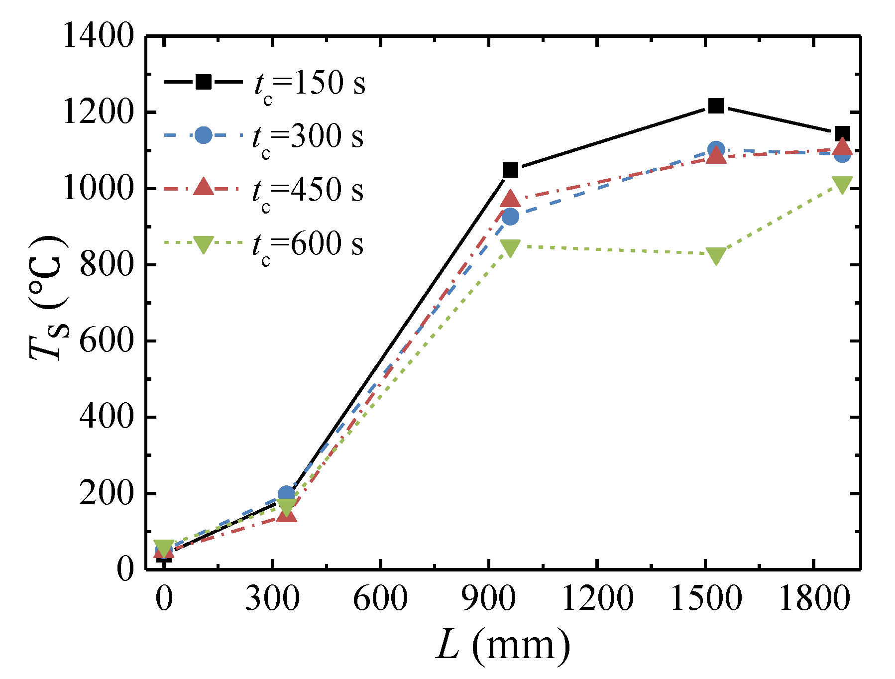
3.5. Effect of the Cycle Time

Figure 14 shows the solid temperature profile along the axial direction with different cycle times. The solid temperature gradually decreases with increasing cycle time. As shown in Figure 15, when the cycle time increases from 150 s to 600 s, the temperature difference between the hot gas withdrawal flow and the inlet gas decreases from 1109 °C to 981 °C, respectively. The outlet-inlet temperature difference gradually increases with increasing cycle time, and the heat recovery efficiency gradually decreases from 74.9% to 69.3% with increasing cycle time.

4. Conclusions

An industrial-scale VAM oxidation system was constructed to test the thermal oxidation performance of a multibed TFRR. The influences of the main operating parameters (inlet flow rate, feed methane concentration, and cycle time) on the reactor behavior were investigated in this work. The main conclusions of the current studies are as follows:
(1)
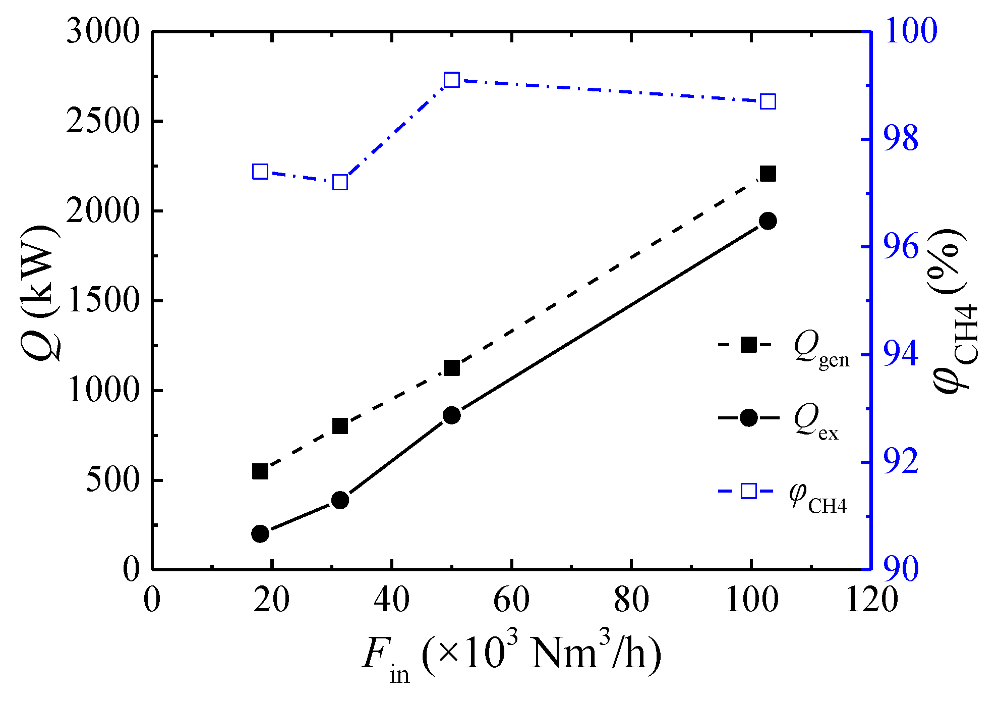
The CSS is asymmetrical due to the hot gas extracted from the combustion chamber. The multibed TFRR achieves a methane conversion higher than 97% for the thermal oxidation of VAM.
(2)
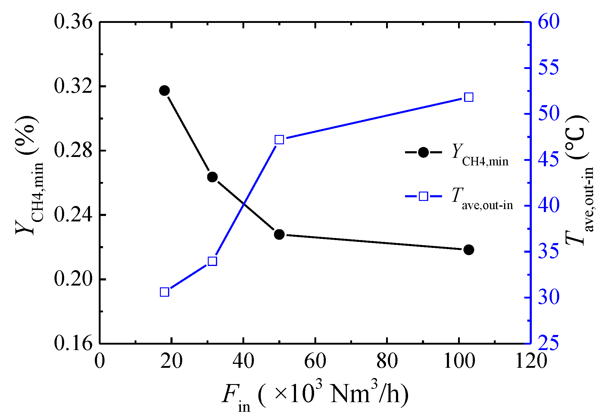
The lower concentration limit of automatic thermal maintenance decreases with increasing flow rate due to the heat dissipation from the reactor surface. At an inlet flow rate of 103,000 Nm3/h and a cycle time of 300 s, the lower concentration limit of automatic thermal maintenance is 0.22 vol %.
(3)
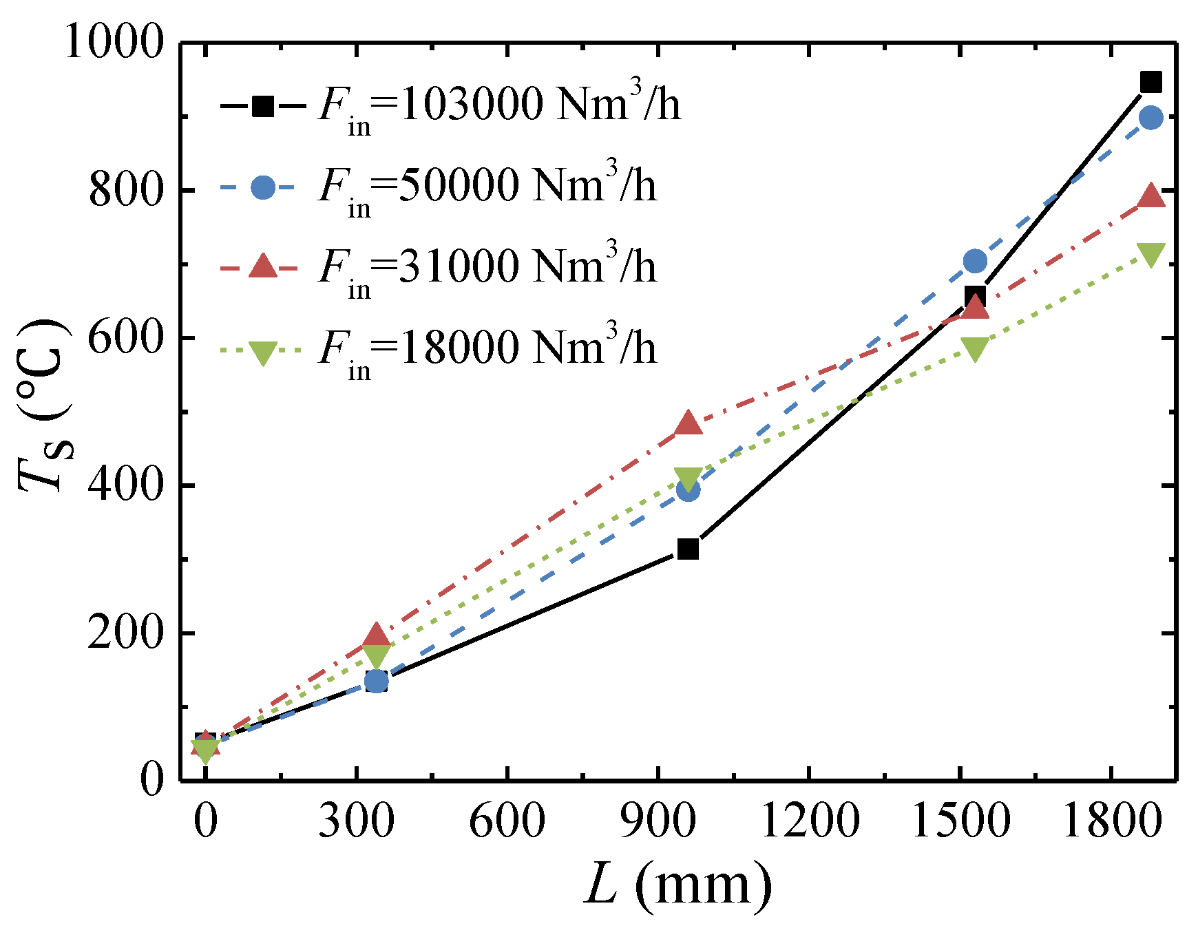
The peak temperature of the bed moves closer to the inlet side with increases in the feed methane concentration and decreases in the cycle time and is almost not affected by the change in inlet flow rate.
(4)
For this multibed TFRR, approximately 76.3% of the energy can be recovered at an inlet flow rate of 110,000 Nm3/h, a feed methane concentration of 1.02 vol %, and a cycle time of 450 s. The heat recovery efficiency increases linearly with increasing inlet flow rate, rises parabolically with an increasing feed methane concentration, and decreases weakly with increasing cycle time.

Author Contributions

B.L. and Y.-R.L. conceived the main idea and wrote the manuscript. X.-S.Z. and J.-D.K. contributed to the experimental work.

Funding

This work was funded by National Science and Technology Major Project of China (Project Number: 2016ZX05045-006).

Conflicts of Interest

The authors declare no conflict of interest.

References

  1. Dalianis, G.; Nanaki, E.; Xydis, G.; Zervas, E. New Aspects to greenhouse gas mitigation policies for low carbon cities. Energies 2016, 9, 128. [Google Scholar] [CrossRef]
  2. Su, S.; Beath, A.; Guo, H.; Mallett, C. An assessment of mine methane mitigation and utilization technologies. Prog. Energy Combust. Sci. 2005, 31, 123–170. [Google Scholar] [CrossRef]
  3. Liu, W.; Han, J.; Zhao, G. Potential and economic analysis of VAM utilization in China. China Coalbed Methane 2009, 6, 3–8. [Google Scholar]
  4. Wang, W.; Wang, H.; Li, H.; Li, D.; Li, H.; Li, Z. Experimental enrichment of low-concentration ventilation air methane in free diffusion conditions. Energies 2018, 11, 428. [Google Scholar] [CrossRef]
  5. Yang, X.; Liu, Y.; Li, Z.; Zhang, C.; Xing, Y. Vacuum exhaust process in pilot-scale vacuum pressure swing adsorption for coal mine ventilation air methane enrichment. Energies 2018, 11, 1030. [Google Scholar] [CrossRef]
  6. Su, S.; Chen, H.; Teakle, P.; Xue, S. Characteristics of coal mine ventilation air flows. J. Environ. Manag. 2008, 86, 44–62. [Google Scholar] [CrossRef] [PubMed]
  7. Karakurt, I.; Aydin, G.; Aydiner, K. Mine ventilation air methane as a sustainable energy source. Renew. Sustain. Energy Rev. 2011, 15, 1042–1049. [Google Scholar] [CrossRef]
  8. Karacan, C.Ö.; Ruiz, F.A.; Cotè, M.; Phipps, S. Coal mine methane: A review of capture and utilization practices with benefits to mining safety and to greenhouse gas reduction. Int. J. Coal Geol. 2011, 86, 121–156. [Google Scholar] [CrossRef]
  9. Yang, Z.; Yang, P.; Zhang, L.; Guo, M.; Ran, J. Experiment and modeling of low concentration methane catalytic combustion in a fluidized bed reactor. Appl. Therm. Eng. 2016, 93, 660–667. [Google Scholar] [CrossRef]
  10. Mei, H.; Li, C.; Liu, H.; Ji, S. Simulation of catalytic combustion of methane in a monolith honeycomb reactor. Chin. J. Chem. Eng. 2006, 14, 56–64. [Google Scholar] [CrossRef]
  11. Marín, P.; Ordóñez, S.; Díez, F.V. Monoliths as suitable catalysts for reverse-flow combustors: Modeling and experimental validation. AIChE J. 2010, 56, 3162–3173. [Google Scholar]
  12. Wang, Y.; Man, C.; Che, D. Catalytic combustion of ventilation air methane in a reverse-flow reactor. Energy Fuels 2010, 24, 4841–4848. [Google Scholar] [CrossRef]
  13. Gosiewski, K. Efficiency of heat recovery versus maximum catalyst temperature in a reverse-flow combustion of methane. Chem. Eng. J. 2005, 107, 19–25. [Google Scholar] [CrossRef]
  14. Marín, P.; Ordóñez, S.; Díez, F.V. Procedures for heat recovery in the catalytic combustion of lean methane-air mixtures in a reverse flow reactor. Chem. Eng. J. 2009, 147, 356–365. [Google Scholar] [CrossRef]
  15. Wang, S.; Gao, D.; Wang, S. Steady and transient characteristics of catalytic flow reverse reactor integrated with central heat exchanger. Ind. Eng. Chem. Res. 2014, 53, 12644–12654. [Google Scholar] [CrossRef]
  16. Fernández, J.; Marín, P.; Díez, F.V.; Ordóñez, S. Experimental demonstration and modeling of an adsorption-enhanced reverse flow reactor for the catalytic combustion of coal mine ventilation air methane. Chem. Eng. J. 2015, 279, 198–206. [Google Scholar] [CrossRef] [Green Version]
  17. Fernández, J.; Marín, P.; Díez, F.V.; Ordóñez, S. Combustion of coal mine ventilation air methane in a regenerative combustor with integrated adsorption: Reactor design and optimization. Appl. Therm. Eng. 2016, 102, 167–175. [Google Scholar] [CrossRef] [Green Version]
  18. Gosiewski, K.; Pawlaczyk, A.; Warmuzinski, K.; Jaschik, M. A study on thermal combustion of lean methane–air mixtures: Simplified reaction mechanism and kinetic equations. Chem. Eng. J. 2009, 154, 9–16. [Google Scholar] [CrossRef]
  19. Pawlaczyk, A.; Gosiewski, K. Combustion of lean methane-air mixtures in monolith beds: Kinetic studies in low and high temperatures. Chem. Eng. J. 2015, 282, 29–36. [Google Scholar] [CrossRef]
  20. Qi, X.; Liu, Y.; Xu, H.; Liu, Z.; Liu, R. Modeling thermal oxidation of coal mine methane in a non-catalytic reverse-flow reactor. J. Mech. Eng. 2014, 60, 495–505. [Google Scholar] [CrossRef]
  21. Lan, B.; Li, Y.R. Numerical simulation of thermodynamic performance in a honeycomb ceramic channel. In Proceedings of the 3rd International Symposium on Mine Safety Science and Engineering, Montreal, QC, Canada, 13–19 August 2016. [Google Scholar]
  22. Gosiewski, K.; Pawlaczyk, A.; Jaschik, M. Thermal combustion of lean methane–air mixtures: Flow reversal research and demonstration reactor model and its validation. Chem. Eng. J. 2012, 207–208, 76–84. [Google Scholar] [CrossRef]
  23. Gosiewski, K.; Pawlaczyk, A.; Jaschik, M. Energy recovery from ventilation air methane via reverse-flow reactors. Energy 2015, 92, 13–23. [Google Scholar] [CrossRef]
  24. Li, Q.; Lin, B.; Yuan, D.; Chen, G. Demonstration and its validation for ventilation air methane (VAM) thermal oxidation and energy recovery project. Appl. Therm. Eng. 2015, 90, 75–85. [Google Scholar] [CrossRef]
  25. Gosiewski, K.; Matros, Y.S.; Warmuzinski, K.; Jaschik, M.; Tanczyk, M. Homogeneous vs. catalytic combustion of lean methane-air mixtures in reverse-flow reactors. Chem. Eng. Sci. 2008, 63, 5010–5019. [Google Scholar] [CrossRef]
  26. Gosiewski, K.; Pawlaczyk, A. Catalytic or thermal reversed flow combustion of coal mine ventilation air methane: What is better choice and when? Chem. Eng. J. 2014, 238, 78–85. [Google Scholar] [CrossRef]
Figure 1. Diagram of the industrial-scale VAM oxidation system 1: flow control valve, 2: gas mixer, 3: methane concentration sensor, 4: flow sensor, 5: fan, 6: combustion fan, 7: thermocouples, 8: flow control valve for high-temperature gas, 9: diesel burner, 10: multibed TFRR, 11: honeycomb ceramics, 12: switching valves (V1-V15), 13: purging fan.
Energies 11 01578 g001
Figure 2. On-site, industrial-scale VAM oxidation system: (a) Photograph of the system; (b) TFRR (lower) and boiler (upper).
Energies 11 01578 g002
Figure 3. Monitoring data for the flow rate (Fin) and methane concentration (YCH4,in) at the inlet during five cycles when Fin = 105 × 103 Nm3/h, YCH4,in = 0.94 vol %, and tc = 450 s.
Energies 11 01578 g003
Figure 4. Solid temperature (Ts) profiles along the length (L) of the TFRR at the end of the heat-releasing, purging, and heat-absorbing stages in the five regenerator beds when Fin = 105 × 103 Nm3/h, YCH4,in = 0.94 vol %, and tc = 450 s.
Energies 11 01578 g004
Figure 5. Solid temperature (Ts) fluctuation at the monitoring points in bed 1 during five cycles when Fin = 105 × 103 Nm3/h, YCH4,in = 0.94 vol %, and tc = 450 s.
Energies 11 01578 g005
Figure 6. Monitoring data for the rate of hot gas withdrawal flow (Fdraw), the temperature difference between the hot gas withdrawal flow and inlet gas (Tdraw-in), and the outlet-inlet gas temperature difference (Tout-in) during five cycles at Fin = 105 × 103 Nm3/h, YCH4,in = 0.94 vol %, and tc = 450 s.
Energies 11 01578 g006
Figure 7. Solid temperature (Ts) profile in bed 1 along the length (L) of the TFRR at the end of the heat-absorbing state for automatic thermal maintenance with different inlet flow rates (Fin).
Energies 11 01578 g007
Figure 8. The lower concentration limit (YCH4,min) and average outlet-inlet temperature difference (Tave,out-in) during self-maintained operation with different inlet flow rates (Fin).
Energies 11 01578 g008
Figure 9. Heat generated by methane reaction (Qgen), heat loss of exhaust gas (Qex) and methane conversion (φCH4) during self-maintained operation with different inlet flow rates (Fin).
Energies 11 01578 g009
Figure 10. Solid temperature (Ts) profiles of bed 1 along the length (L) of the TFRR for different inlet flow rates (Fin) at the end of the cycle at YCH4,in ≈ 1 vol % and tc = 450 s.
Energies 11 01578 g010
Figure 11. Temperature difference between the hot gas withdrawal flow and inlet gas (Tdraw-in), outlet-inlet gas temperature difference (Tout-in), and heat recovery efficiency (η) for different inlet flow rates (Fin) at YCH4,in ≈ 1 vol % and tc = 450 s.
Energies 11 01578 g011
Figure 12. Solid temperature (Ts) profile of bed 1 along the length (L) of the TFRR for different feed methane concentrations (YCH4,in) at the end of the cycle when Fin ≈ 105 × 103 Nm3/h and tc = 300 s.
Energies 11 01578 g012
Figure 13. Temperature difference between the hot gas withdrawal flow and inlet gas (Tdraw-in), outlet-inlet gas temperature difference (Tout-in), and heat recovery efficiency (η) for different feed methane concentrations (YCH4,in) at Fin ≈ 105 × 103 Nm3/h and tc = 300 s.
Energies 11 01578 g013
Figure 14. Solid temperature (Ts) profiles of bed 1 along the length (L) of the TFRR for different cycle times (tc) at the end of the cycle when Fin ≈ 105 × 103 Nm3/h and YCH4,in = 0.95 vol %.
Energies 11 01578 g014
Figure 15. Temperature difference between the hot gas withdrawal flow and inlet gas (Tdraw-in), outlet-inlet gas temperature difference (Tout-in), and heat recovery efficiency (η) for different cycle times (tc) at Fin ≈ 105 × 103 Nm3/h and YCH4,in = 0.95 vol %.
Energies 11 01578 g015
Table 1. Valve-switching schedule for the multibed TFRR.
CycleValves of Bed 1Valves of Bed 2Valves of Bed 3Valves of Bed 4Valves of Bed 5
V1V2V3V4V5V6V7V8V9V10V11V12V13V14V15
1/5 cycleO××O×××O×××O××O
2/5 cycleO×××O×××O××OO××
3/5 cycle×O×××O××OO××O××
4/5 cycle××O××OO××O×××O×
5/5 cycle××OO××O×××O×××O
Notes: O: open; ×: shut.
Table 2. Summary of the operating conditions and results for methane conversion (φCH4) and heat recovery efficiency (η) of the experiments.
CaseFin
(×103 Nm3/h)
YCH4,in
(vol %)
tc
(s)
φCH4
(%)
η
(%)
Case 11050.9445099.172.7
Case 21030.2230098.70
Case 3500.2345099.10
Case 4310.2645097.20
Case 5180.3245097.40
Case 61101.0245099.876.3
Case 7750.9845097.570.2
Case 8521.0645099.766.5
Case 91050.9430097.770.8
Case 101060.713009969.2
Case 111070.403009943.1
Case 121030.953009774.9
Case 131060.9560099.869.3

