Review

AC Ship Microgrids: Control and Power Management Optimization

by
Monaaf D. A. Al-Falahi
1,
Tomasz Tarasiuk
2,
Shantha Gamini Jayasinghe
1,*,
Zheming Jin
3,
Hossein Enshaei
1 and
Josep M. Guerrero
3
1
National Centre for Ports and Shipping, Australian Maritime College, University of Tasmania, Tasmania 7248, Australia
2
Department of Marine Electrical Power Engineering, Gdynia Maritime University, Gdynia 81225, Poland
3
Institute of Energy Technology, Aalborg University, Aalborg 9100, Denmark
*
Author to whom correspondence should be addressed.
Energies 2018, 11(6), 1458; https://doi.org/10.3390/en11061458
Submission received: 22 March 2018 / Revised: 29 May 2018 / Accepted: 4 June 2018 / Published: 5 June 2018

Abstract

:
At sea, the electrical power system of a ship can be considered as an islanded microgrid. When connected to shore power at berth, the same power system acts as a grid connected microgrid or an extension of the grid. Therefore, ship microgrids show some resemblance to terrestrial microgrids. Nevertheless, due to the presence of large dynamic loads, such as electric propulsion loads, keeping the voltage and frequency within a permissible range and ensuring the continuity of supply are more challenging in ship microgrids. Moreover, with the growing demand for emission reductions and fuel efficiency improvements, alternative energy sources and energy storage technologies are becoming popular in ship microgrids. In this context, the integration of multiple energy sources and storage systems in ship microgrids requires an efficient power management system (PMS). These challenging environments and trends demand advanced control and power management solutions that are customized for ship microgrids. This paper presents a review on recent developments of control technologies and power management strategies proposed for AC ship microgrids.

1. Introduction

Diesel engine driven or gas turbine driven generators are the sources found in conventional ship microgrids, which are generally known as gensets. They are controllable sources and thus their power levels can be adjusted to meet the required demand. With the growing demand for emission reduction and fuel efficiency improvements these conventional gensets must be supplemented with alternative energy sources such as wind, solar, and fuel cells [1,2,3,4]. Even though there are different opinions on solar and wind installations on shipboards, as their contribution to the power generation is not significant compared to gensets, in certain ship types, the contribution can be non-marginal, and thus a growing trend can be observed in research and relevant technology development in these areas [5,6]. Out of these alternative energy sources, the fuel cell has been identified as the most promising technology for ships [4,7]. In addition to the incorporation of alternative energy sources, energy recovery technologies are increasingly being introduced into ship microgrids aiming towards improving the fuel efficiency [8]. For example, waste heat recovery systems that utilize exhaust fumes for electricity production are able to improve main engine efficiency by approximately 5%, which greatly reduces emissions and fuel cost [3,9].
Even though these alternative energy technologies help improve fuel efficiency and reduce emissions, their intermittency and/or slow response make energy storage technologies such as batteries or supercapacitors essential to ensure reliable operation and fast response [10]. Moreover, the presence of pulse loads, such as radar, may exceed the ship’s rated generation capacity, leading to unstable operation [11,12,13]. This makes energy storage inevitable in shipboard power systems to meet fast transient characteristics [4,14,15,16,17]. Therefore, future ship power systems will include traditional gensets, alternative energy sources, energy storage technologies, and energy recovery systems.
Together with the aforementioned technologies, the ship power system can be considered as a typical islanded microgrid when the ship is at sea. The same power system can be considered as a grid connected microgrid or an extension of the shore power grid when the ship is at berth. Thus, ship microgrids show some resemblance to terrestrial microgrids [18,19,20]. Nevertheless, the major difference comes from the way the load and source dynamics are distributed in each system. In terrestrial microgrids, renewable energy sources account for a large share of power and thus they bring associated intermittencies into the power generation system while the loads show relatively small and slow changes [21,22,23]. In contrast, the main sources in ship microgrids are controllable, while the loads, such as propulsion loads, are highly dynamic. In addition, the presence of large power electronic loads is another major difference in ship microgrids, which results in serious power quality issues compared to terrestrial microgrids [2,24]. Therefore, despite some similarities, ship microgrids require special attention in research and associated technology developments.
The major challenge with such islanded microgrids is matching the source dynamics to that of the loads while ensuring robust operation and fast response [25]. Control and power management strategies play a vital role in achieving these objectives [26,27,28,29,30,31,32,33]. Droop and isochronous are the commonly used primary control technologies in AC or DC ship microgrids [27]. On top of these controllers, there should be a centralized or decentralized power management controller to coordinate power generation. Hierarchical control, which is one of the popular approaches reported in the literature for power management and the control of islanded microgrids, can be adopted for ship microgrids as well [26]. Three-level hierarchical control is the most common scheme, and in this scheme the primary control focuses on individual units while the secondary and tertiary controls focus on system level control and power management, respectively [20,26]. In contrast to the common centralized control approach, distributed control, especially with multi-zonal architectures in emerging ship power systems, enables robust operation even during faults in part of the ship microgrid [34,35]. The aim of this paper is to present a review of the advancements of architectures, control technologies, and power management strategies of ship microgrids. Moreover, the author’s original research on the performance of droop control based power sharing, at different operating conditions, are presented. This paper serves as a useful reference for academic researchers and practicing engineers in the field of ship microgrids.

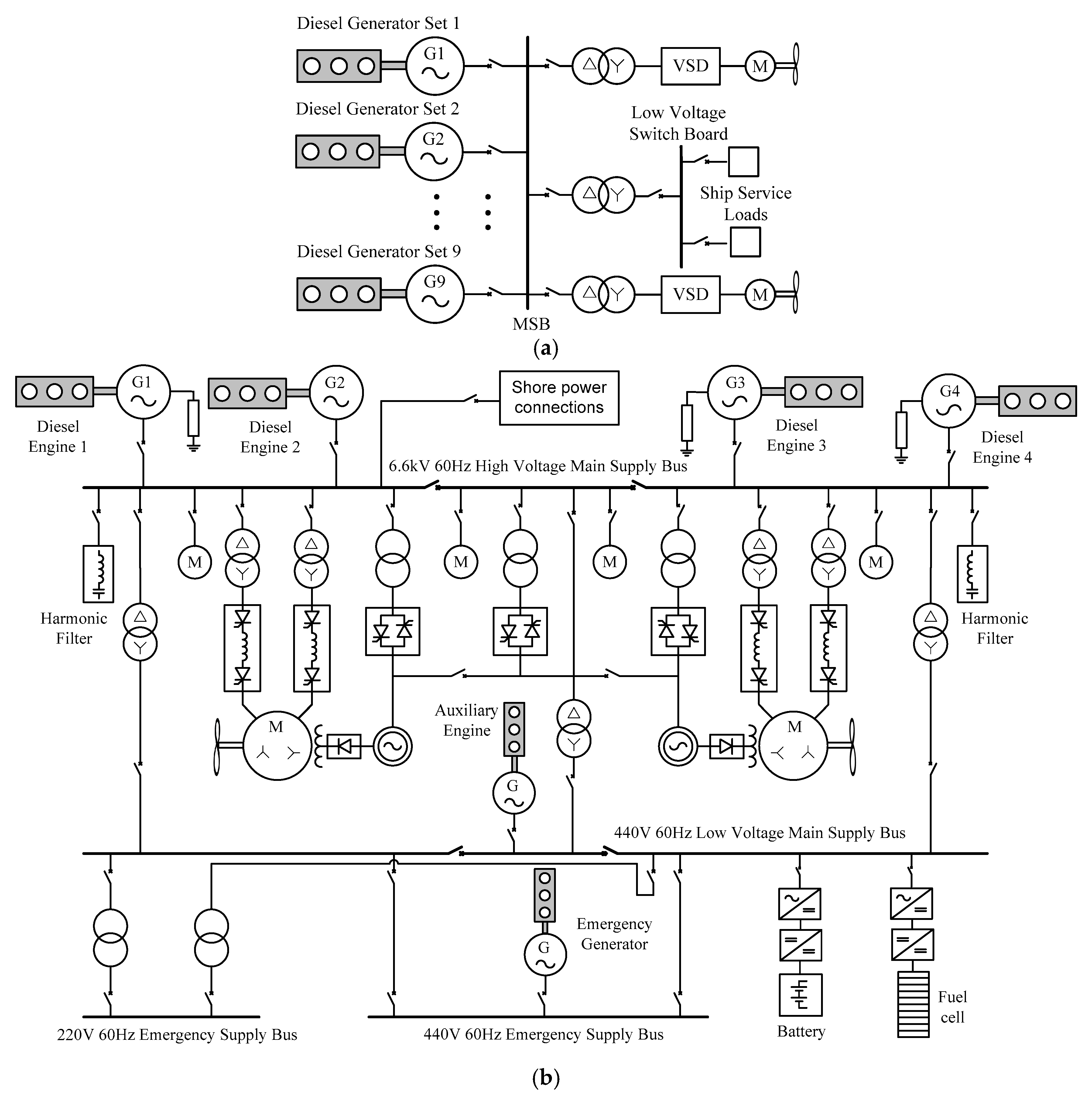
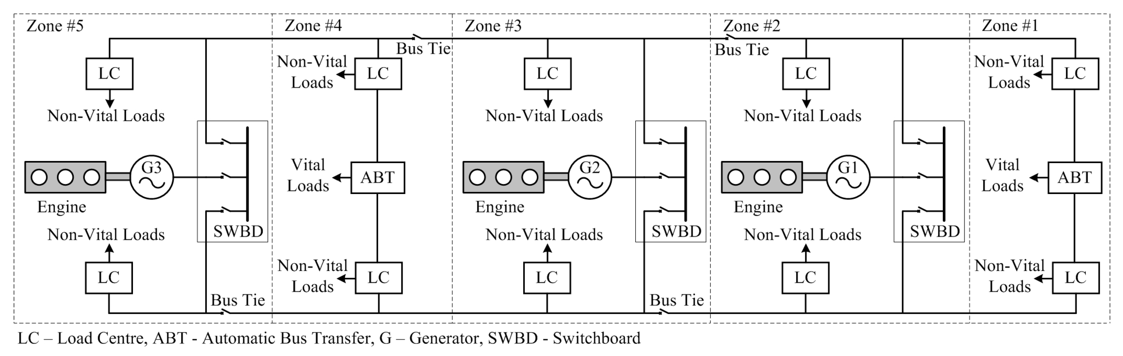
2. Shipboard AC Power System Architectures

Ship microgrids generally follow the shore practice and thus, 400 V/50 Hz or 440 V/60 Hz three phase low voltage (LV) AC distribution systems are common in a majority of the ships. This allows normal industrial equipment, which designed to withstand harshness at sea, to be used on ships. This equipment generally constitutes ships auxiliary service loads. Compared to these service loads, propulsion loads are very high, and thus the LV distribution system is not sufficient to cater to these loads. Therefore, high voltage (HV) three-phase distribution systems, such as 3.3 kV, 6.6 kV, and 11 kV, are used to transmit power to these loads. Owing to these differences in voltage levels, power requirements and dynamics, propulsion, and service loads were segregated in early electric ships [3]. Nevertheless, due to the fact that finding solutions to the above challenges is more beneficial than maintaining two systems, the trend has now been shifted from segregated power systems to integrated power systems (IPSs).
The history of surface ship electric propulsion is dated to the beginning of the last century, when this system was installed onboard the U.S.S. Jupiter, followed by other vessels, most prominently passenger ships, like the Queen Elizabeth II (QEII) [3]. QEII uses an IPS where propulsion loads are fed through the HV distribution system and service loads are fed through the LV distribution system, as shown in Figure 1a. The LV bus is fed from the HV bus through a step down transformer [36]. In this architecture, all the generators are connected to a single HV bus, which run the risk of blackout if there is a failure at the HV side. As a solution, instead of having a single HV bus, the two HV/LV radial bus architectures, shown in Figure 1b, have been used in many ships [37,38]. The two busses, generally referred to as the port side bus and starboard side bus, are linked with bus-tie switches. These switches can be opened to disconnect the faulty bus from the healthy bus in the event of a fault and thus potential blackouts can be prevented. Moreover, owing to the progressive development in power electronics devices, the integration of more-electric technologies (METs) is gaining more attention in the marine industry. In this context, with the growing demand for emission reductions and fuel efficiency improvements, the integration of renewable energy sources and energy storage systems is becoming popular in the maritime industry. A typical arrangement for integrating such systems into a shipboard power system is shown in Figure 1b [39].
Similar to QEII, the LV side of the radial distribution system is also supplied by the HV side through transformers. But, unlike in QEII, the LV side is also divided into two busses linked through bus tie switches in the radial system. This helps isolate LV buses as well in the event of a fault. Moreover, there is an auxiliary generator, which can be used to feed the LV bus if the power from the HV side is insufficient or unavailable. In addition, the emergency power supply, shown in Figure 1b, is a requirement under safety of life at sea (SOLAS) regulations, which should be available for emergency lighting, alarms communications, water tight doors, and other services that are necessary to maintain safety in the event of main power failure [38]. This can be a battery bank, a generator, or both.
Even in the radial distribution system, there could be possibilities for losing power to the essential loads, such as propulsion motors, in the event of a fault in a HV bus. Moreover, certain sections might not be able to isolate without affecting some of the essential loads attached to it [35]. As a solution, modern electric ships tend to use zonal electrical distribution system (ZEDS) architecture based IPSs over radial architecture [40,41]. The principle feature of ZEDSs is that the entire network is split into a few sections (IEEE Std 45.3-2015 [42]), as shown in Figure 2, called zones, which are connected through bus-tie switches. Each zone has its own load center, which is powered by generating sources. All the zones are connected by a starboard bus and a port bus. One of those buses is located above the water line, while the other is positioned below to increase the distance between them, and to reduce possible damages to both busses in case of fault [40].
Ship power systems are generally ungrounded. This is to limit the risk of system collapse in the event of a single fault. Nevertheless, HV systems inevitably lead to the increased risk of transient overvoltage due to a phase-to-earth arc flash. Therefore, instead of ungrounded systems, ships with HV distribution systems use high resistance grounding [43].

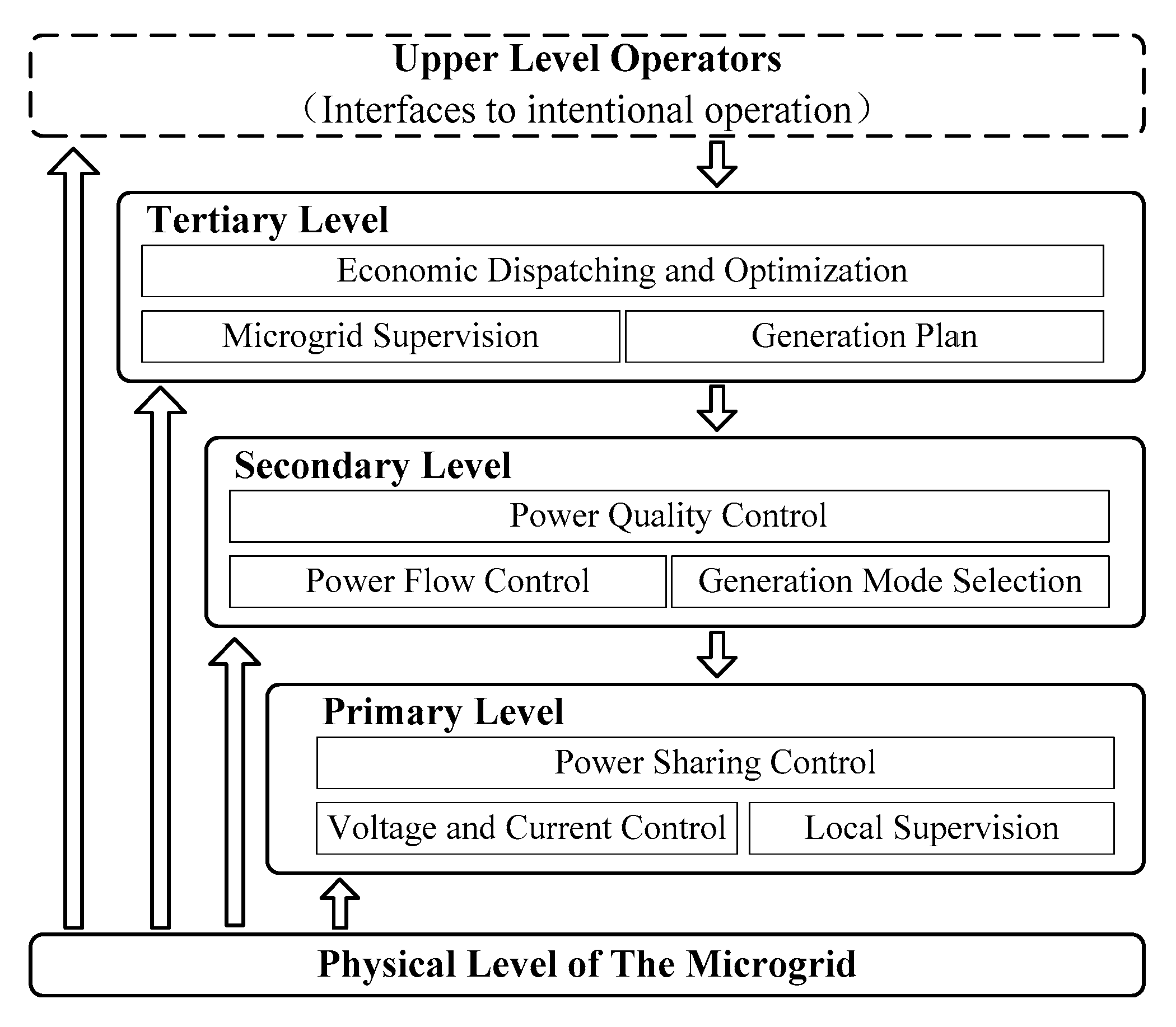
3. Control Technologies

Power generation in ship microgrids is dominated by synchronous generators, which are controllable. However, the loads are highly dynamic and, in certain cases, may contain unpredictable fast changes. Therefore, in order to manage complexities and achieve desired control objectives, the hierarchical framework, which is shown in Figure 3, can be adopted forship microgrids as well [25,44]. Moreover, as explained below, the existing control technologies in ship power systems can also be described in line with the hierarchical control framework. In hierarchical control, the primary level objective is to achieve load sharing among the power sources. The secondary level control objective is to secure bus signals at their nominal values. The tertiary level control is used to achieve optimal operation with intentional objectives [26]. In this scheme, the higher the level of control, the slower the regulation it provides. Moreover, the scope of the control widens as the level increases.

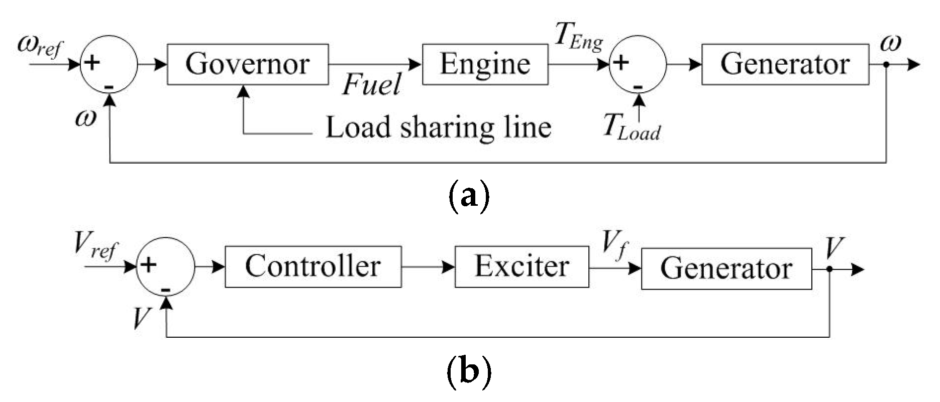
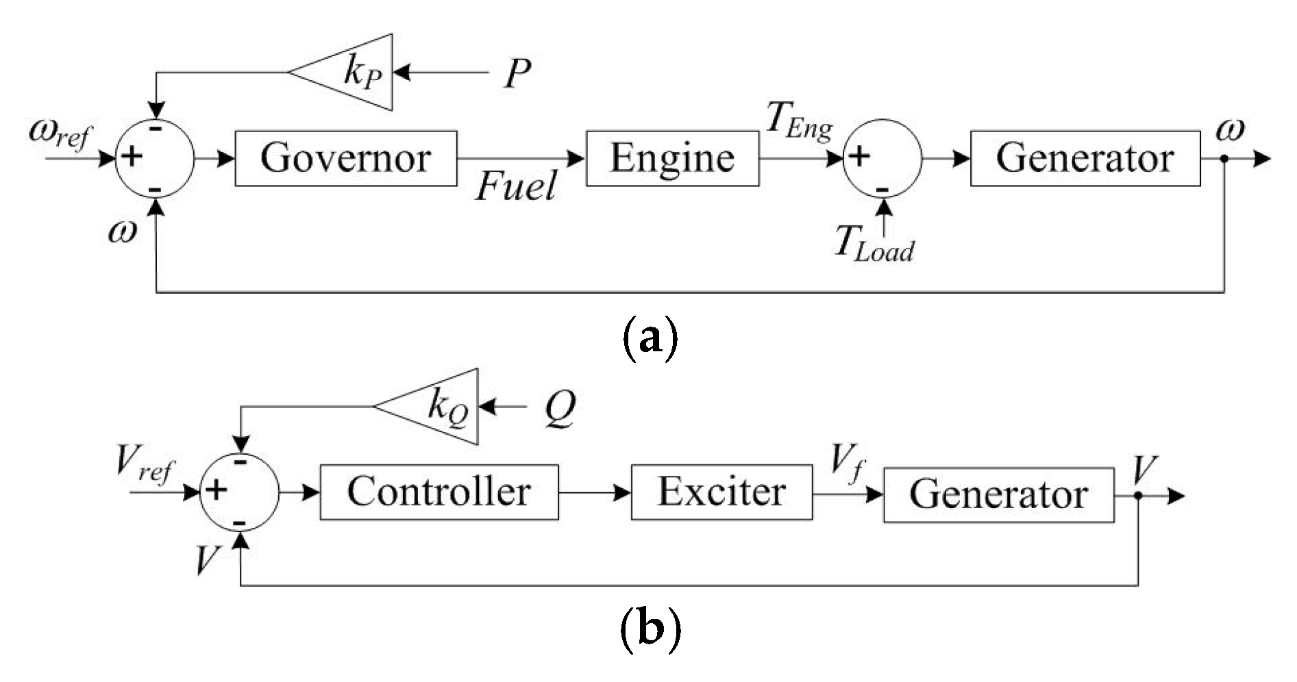
3.1. Isochronous Control
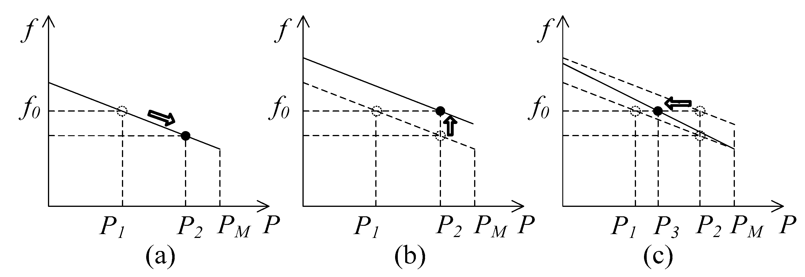
The majority of shipboard power systems are AC distribution systems, where frequency and voltage are the two fundamental parameters to be maintained within specified limits. Since diesel engine or gas turbine driven synchronous generators are the commonly used sources in these systems, the governor controller regulates the frequency while the automatic voltage regulator (AVR) regulates the voltage. The governor, which comes in the form of a hydro-mechanical controller or an electronic controller, controls the fuel supply to the engine and in turn regulates the speed, (ω), of the rotor. The AVR comes as an electronic controller and it controls the current supplied to the field winding of the generator, which in turn regulates the output voltage, (V). Simplified block diagrams of these two controllers are shown in Figure 4.
The controller shown in Figure 4a is known as an isochronous speed controller, as it regulates the speed of the engine at the set point [45]. Under isochronous control, both the voltage and frequency of the generator output are maintained at set points irrespective of changes in the load. In comparison to the hierarchical control framework, the isochronous control for a single generator falls within the scopes of primary and secondary levels as it regulates the bus voltage and frequency at set points, while supplying the demanded power.
The aforementioned isochronous control works well for a single generator. If two or more generators are connected to the same power bus, one of the engines may try to take the entire load while the others might not take the load. This leads to instabilities and may result in blackout. Therefore, in order to solve this issue, communication between the governor controllers, in the form of a load sharing line or a communication link, such as controller area network (CAN) bus or Field bus, is required [46]. With the help of the communication link, each engine can be set to take a specific share of the load without going into extremes or instabilities. In this configuration, the power management system (PMS), which determines the power reference for each engine, can be attributed to the tertiary level of the hierarchical control framework.
Even though isochronous load sharing is capable of regulating voltage and frequency at set points, it has not become the popular choice in ship microgrids, mainly due the harshness of the environment in ships, which adversely affects communications. Moreover, in order to implement isochronous power sharing, all the governor controllers should be compatible, and most of the cases should come from the same manufacturer, which may not be possible in some cases. Even though solutions such as advanced generator supervision (AGS) have been developed to prevent blackout in faulty situations, isochronous control is still not the popular choice when it comes to very large shipboard power systems [47].

3.2. Droop Control

Compared to isochronous control, droop control is the popular choice for power sharing in multi-generator shipboard power systems, as it does not require communication between the governor controllers. In contrast to the fixed frequency and fixed voltage operation in the isochronous control, droop control lets the frequency and voltage vary in proportion to the active, (P), and reactive power, (Q), demands of the load. The corresponding speed and voltage controllers are shown in Figure 5, where the speed and voltage references are reduced linearly as the active and reactive power demands increase.
The droop control matches with the inherent P/f droop nature of synchronous machines where loads on the electrical side slows down the rotor and as a result, speed drops [48]. The governor injects more fuel in response to the speed drop and thus, as shown in Figure 6a, the genset becomes stable at a new frequency, which is lower than the nominal frequency, f0. Not only the frequency but also the voltage settles at a new value in the same way when there is a change in the reactive power demand [45]. In a multi generator system, each governor senses the speed drop, supplies more power to the grid and finally settles at a new frequency. The amount of power supplied by each genset depends on the droop settings of the genset. If the settings are equal, all the generators equally share the load. Moreover, the droop control can be applied for power converter based systems as well. However, irrespective of the system, droop based power sharing falls within the scope of the primary response in the hierarchical control scheme [48].
In a multi-generator system, the secondary control can be used to bring the frequency back to the nominal value, as shown in Figure 6b, by adding an offset to the speed reference, ωref. This is known as the secondary response that can be attributed to the level 2 control of the hierarchical control scheme. As shown in Figure 6c, further changes can be made to the droop controller by changing the droop gain, kp, which changes the power levels of each engine to their best possible levels under the given condition. This tertiary response belongs to the level 3 control of the hierarchical scheme. Similar to the abovementioned speed, droop controllers operate based on the reactive power demand [26,48]. According to the rules of most of ship classification societies, the proportionality of load sharing has to be within the range of ±15% of the rated active power and ±10% of the rated reactive power of the largest generator [3,49,50,51].
In contrast to isochronous control, droop control requires only local measurements of voltage and frequency, and thus, it allows multiple generators to share the load without hunting and without the need of inter-unit communication. This makes droop control robust, highly reliable, and flexible in adding/removing the generators of different power ratings to the grid [52,53]. Nevertheless, since the active and reactive power supplied by generators depend on frequency and voltage deviations, large loads result in increased deviations, and this is an inherent trade-off of droop control [39,53,54,55].

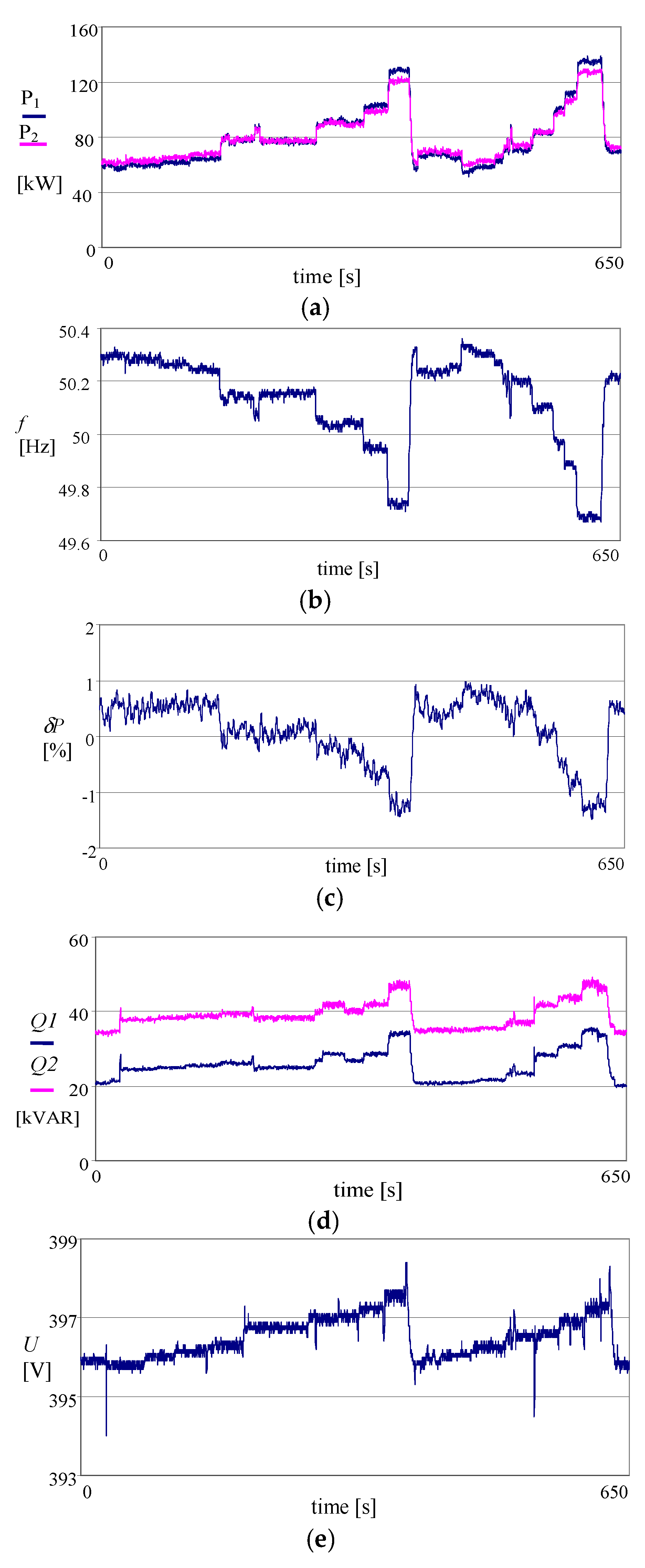
3.3. Application of Droop Control—Tests in a Real Ship

In order to exemplify the real system behavior of droop control under highly non-linear loading conditions, the results of an experiment conducted in a ship are presented in Figure 7. During the experiment, two generators of 301 kW (376 kVA) rated power worked in parallel. The generators were driven by diesel engines, each having 357 kW of rated power. Mechanical-hydraulic governors were used to control the shaft speed of the prime movers. Despite the medium rated power of the gensets, they displayed the typical behavior of a ship electric power plant with a droop control scheme. The most significant load was the bow thruster drive with a rated power of 125 kW, supplied via a power converter. This bow thruster should be considered as a highly non-linear load.
The frequency droop is clearly visible in Figure 7b. It enables fast and satisfactory load sharing between the generators. The proportionality of active power sharing is shown in Figure 7c, which is within the limits of ship classification societies. It is worth noting here that this observation was made despite having slight differences in the characteristics of the two governors. The reactive power supplied by each generator is shown in Figure 7d. Even though the sharing of reactive power is disproportional, the difference is small in comparison to rated power and thus the relative sharing is safely within 2.8–3.2% of the rated reactive power of each generator. Furthermore, as shown in Figure 7e, it can be seen that the load increase results in an increase in the bus voltage. It is due to the impact of a concurrent increase in the levels of voltage and generator current distortions and their impact on the AVR’s work. The voltage of the total harmonic distortion (THDu) during the process increased from 0.9% to 4.5%, and the current THD increased from 1.7% to 16.7%. The impact of the distortions on the work of AVRs on the same ship was investigated during other research [56]. It was found out that THDu = 3.7% U = 399.7 V, THDu = 4.8% U = 400.4 V, and THDu = 7.9% U = 401.9 V. Thus, reactive load sharing by droop control can be adversely affected by voltage and current distortions.

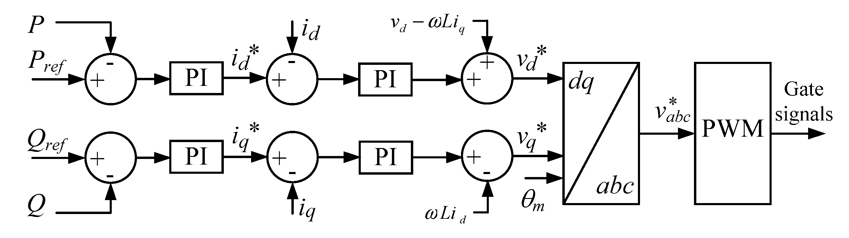
3.4. Grid-feeding Power Converter Control

As discussed in the introductory section, the ever growing trend for low emission technologies and the demarcation of the emission controlled areas (ECAs) resulted in a trend to incorporate more renewable energy technologies, such as fuel cells, photovoltaic (PV) power systems, wind energy conversion systems, and energy storage technologies such as batteries and supercapacitors [4]. Nevertheless, due to relatively low power levels these technologies cannot perform as grid-forming sources. Therefore, the corresponding grid connecting inverters are often used as a grid feeding converter where the converter injects a specific amount of power to the grid depending on the output of the maximum power point tracking algorithm [57] or the command from the ship PMS [48]. Current control is preferred in this mode of operation and thus the interfacing converter can be considered as a current source. Batteries and supercapacitors are used to absorb power fluctuations and thus they work mostly at transient conditions. Therefore, their power reference is generally derived from voltage/frequency stabilization algorithms.
A typical grid-feeding converter controller block diagram is shown in Figure 8. The inner controller consists of a fast current control loop that regulates the current, i, injected into the grid and thus the power delivered to the objectives [48,53]. The synchronous reference frame based dq-frame control is often used in these inner current control loops. Nevertheless, unbalanced grid conditions and the presence of harmonics degrades the performance of the synchronous reference based control. Proportional resonant (PR) controllers solve the harmonic issue with properly tuned resonant to suppress the effects of harmonics [58]. Moreover, the natural reference frame (abc) based controllers, realized in the form of proportional integral (PI), PR, and hysteresis for dead-beats, can be used to control the grid feeding converter [59].

4. Power Management Optimization

Ship PMS plays a vital role in maintaining the power balance, improving fuel efficiency, preventing blackouts, and ensuring safe operation at various operating conditions. The broader scope of the PMS includes power saving, control of propulsion machinery, control of main and emergency generators, loading and unloading of generator alternator sets, load dependent start/stop, load sharing, load shedding, motors automatic blocking, power and frequency control, synchronizing, and monitoring and load analysis illustration. These functionalities fall within the secondary, tertiary, and upper level control of the aforementioned hierarchical control scheme. Some of these functions are explained in detail below.
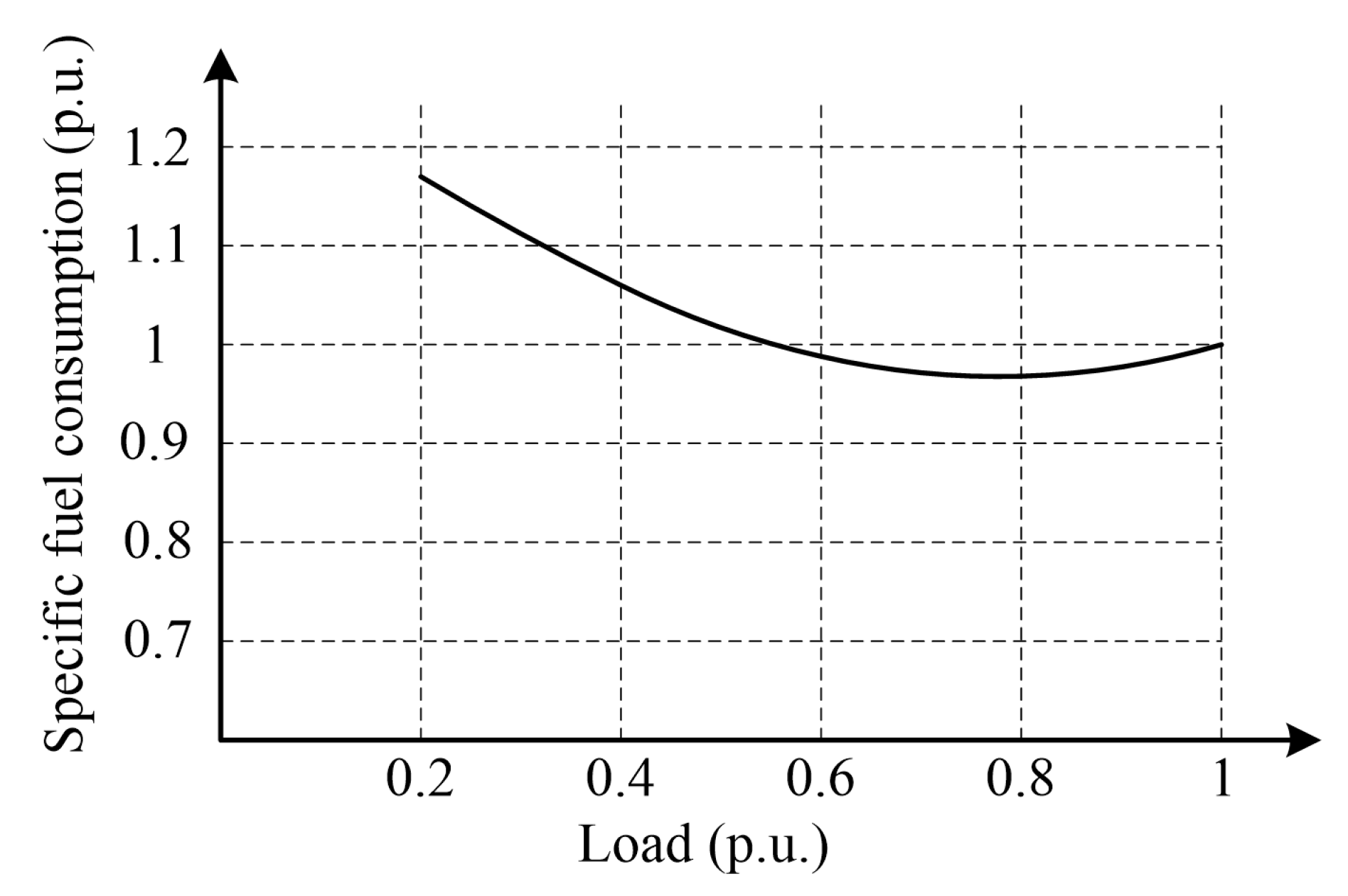
  • Energy saving: Energy savings can be presented in the three following ways: reduction in specific fuel consumption (SFC), reduction in propulsion fuel consumption, and reduction in overall vessel fuel consumption.
  • Automatic start/stop/standby of auxiliary generators: Generators are operated depending on power consumption. A surplus of available power should be limited as much as possible from safety point of view. The PMS constantly compares the total generator load against the load dependent automatic start/stop limits. If the available power minus safety margin is less than the required power, either due to increase in load or fault in a running generator set, the PMS will automatically start the next standby generator set in the start sequence. When the load decreases to a level that will not overload the remaining generators, the standby generator will stop and disconnect.
  • Automatic load sharing: When the load increases, another generator is connected to the switchboard. PMS divides the load in an optimal manner on generators after synchronizing.
  • Load shedding: When a sudden loss of a generator or load increase occurs, leading to an overload of other generators, non-essential loads are automatically disconnected by the PMS. For example, thrusters can operate with reduced load in dynamic positioning for a period of time because of the slow response of the ship with respect to position and handling. This period is sufficient to get the next unit on-line and increase the power generating capacity. According to [50], the PMS “is to prevent overloading of the generators and maintain power to the essential loads such as propulsion load by shedding non-essential loads.”
  • Automatic synchronizing and system restoration: Automatic synchronizing is performed in order to ensure generators are running at required speed, voltage, and phase. After a blackout, the system is required to follow the sequence control of a start-up and reconfiguration of the power system, which includes starting and synchronizing generator sets and sequential starts of loads.
  • Monitoring and load analysis illustration: The PMS consist of a monitoring system to monitor the load profile, active and reactive load sharing monitoring to monitor the load sharing failure, fuel consumption monitoring, graphically displayed information that can help operators to target wasted energy, and engine performance monitoring. Additionally, some PMS monitoring systems provide historical data to help make decisions on the maintenance and operation of machinery and other ship power system components [48].
  • Load transfer: The PMS can control and monitor the load transfer from shaft to auxiliary and vice versa in hybrid electric ships, and shore power to auxiliary in cold ironing [60].
The load type and condition plays a vital role in determining the efficiency of power management for vessels. Hence, the appropriate PMS can be fitted based on the types of loads present onboard the ship and their dynamics. For tanker ships, pumps and compressors are significant factors as they consume a significant portion of the generated power. In cruise ships, approximately 50% of total fuel consumption is consumed by hotel loads such as air conditioning systems, heating systems, galley equipment, stage equipment, and lights. For container ships, cargo handling equipment plays a dominant role and defines the special power requirement characteristics of the installed power system onboard. Moreover, in certain vessels, ballast water pumps present a large load on the ship power system.
Similar to the terrestrial microgrids, power management in a ship’s microgrid can also be implemented in centralized or decentralized manners. A centralized management system requires computation resources and data gathered from internal microgrid components in the case of an islanded microgrid, and from external components in the case of a grid connected microgrid. Centralized PMS, used to achieve the minimum operational costs with efficient operation, gives the advantages of wide observation of the whole system and this type of system is easy to implement [61]. However, a single point of failure in the centralized PMS will affect the entire system [62]. On the other hand, decentralized PMS is preferred when more flexibility in operation and a non-single point of failure system is required. Due to the dynamic nature and finite generation inertia associated with IPSs, decentralized PMS is preferred to achieve the balance between generation and load in real time while satisfying the operational constraints [63,64,65].
With the incorporation of alternative energy technologies, energy recovery technologies, and energy storage systems, ship PMS becomes a key element in optimizing energy usage and thereby improving fuel efficiency. In contrast to terrestrial microgrids, there are many constraints associated with the optimization of ship PMS as it is heavily influenced by dynamic loads [66]. Moreover, the objectives of the optimal power management for ship microgrids depend on the operating conditions of the ship, which can be generally classified into emergency, alert, restorative, reconfigurative, cruise, acceleration, deceleration, and docking [25,67].
Researchers have proposed various optimal power management techniques using classical and meta-heuristic optimization methods by considering the minimization of operational costs and greenhouse gas emissions as their main objective function [68,69,70,71]. In [11], the authors have proposed a model predictive control (MPC) based energy management strategy in order to optimally operate the system by dealing with power ramp rate problems for all-electric ships (AES). The proposed hybrid EMS is a combination of heuristics and MPC in which heuristics are applied to distinguish the system’s state transitions and MPC is applied to fulfill the control objective function in each state. Another study, reported in [72], proposed an adaptive MPC for AES energy management, which provides better energy management compared to the use of MPC alone. In [73], the authors have proposed a multi-objective optimization with real-time MPC for electric ships. The results revealed that the use of the proposed method provides less energy storage losses than MPC. In [74], authors proposed a fuzzy-based particle swarm optimization (FPSO) as a power management strategy for ship electric power systems, comprising integrated full electric propulsion, energy storage, and shore power supply. The main multi-objective function of the optimization is to minimize operating cost and greenhouse gas emissions. The proposed method provides better results in terms of minimum operational costs and greenhouse gas emissions compared to conventional PSO. In other studies, Genetic Algorithm (GA) is used to solve optimization problems including reconfiguration and restoration in ship power systems [75,76]. In other studies, trim optimization is used to reduce the fuel cost and emissions by minimizing fuel consumption [77]. Moreover, LINDO optimization software is used to achieve restoration in ship power system by maximizing the restored load and giving priority to vital loads [41]. Biogeography based optimization (BBO) and particle swarm optimization (PSO) are other techniques that can be used in ship microgrids. Out of these methods, GA has been recognized as a more reliable solution for optimal DC voltage and power control in medium voltage DC (MVDC) shipboard power systems [78]. Another study reported in [79] proposed a real-time optimization based on PSO to optimally manage the power of notional MVDC system for a DC ship microgrid.
The multi-agent system (MAS) technique is one of the most advanced and flexible choices in optimal control and power management [80,81,82], where there are multiple agents interacting with each other in a cooperative manner to solve complex problems effectively [81]. Recent researches have revealed that MAS techniques are able to achieve the minimum demand-supply mismatch, while maximizing the capacity of energized loads, by determining the switch statues of loads in DC zones [63,64]. This has further revealed that the system can be operated normally by preventing blackout in the event of a failure in a subsection. In [83], a real-time heterogeneous MAS is proposed to manage power for AES with a DC zonal system. The study found that incorporating real-time control methods with MAS provides better performance than conventional MAS under the frequency load shedding method. Table 1 summarizes recent developments in power management methods proposed for ship microgrids.
Maintaining reliable and secure communications is important for the operation of ship microgrids, especially with decentralized power management and control. Moreover, the communication between devices is time-critical and thus associated algorithms should be able to minimize delay and reduce computational complexity [86]. These requirements are very similar to those of the terrestrial microgrids and thus the communication methods developed for terrestrial microgrids can be extended for ship microgrids as well. An example of such a communication method is a security model based on message authentication code (MAC). This communication method is used for communication between terrestrial microgrid components including network, data, and attack models [87]. This model provides a secured communication environment with faster response and less memory compared with Rivest, Shamir, and Adleman (RSA), digital signature algorithm (DSA), and time valid hash one-time signature (TV-HORS) [88]. In islanded microgrids, low bandwidth communication is used to exchange information between a centralized controller and local controller in the secondary frequency microgrid. Delay margins in communication increase with the increase of gains of the secondary frequency controller which can be compensated by using a gain scheduling approach method [89]. The above-mentioned communication methods can be implemented in future ship microgrids due to their improved real-time response in order to ensure high performance and more reliability in ship microgrids.
Maintaining a low SFC is also another important objective of emerging ship PMS. Preplanned energy management by offline optimization algorithm can be used for fuel saving. However, in practical operation of ships, there are several innumerable contingencies, which influence the vessel operation. Therefore, using preplanned energy management will result in suboptimal fuel efficiency. In the other hand, the use of real-time energy management and optimization will provide more efficient fuel minimization [36,90]. Figure 9 shows a typical SFC curve for a marine diesel-engine [84]. The optimal fuel consumption can be achieved when the engine load is operated at the minimum SFC.
Practically, the minimum SFC point does not represent the minimum fuel consumption of the engine due to power losses. Engine speed can also effect the SFC value as at high speeds it increases due to the increase in friction. At low speeds, it increases due to increased time for heat losses [91]. In addition, load ripples on the generator can cause ripples on the engine SFC. Therefore, fuel consumption can be optimized by minimizing SFC subjected to operational constraints such as engine speed and load ripple [84]. Energy storage systems can be used to absorb load ripples and thereby reduce SFC. This results in on-board emission reductions [66,92]. Additionally, the utilization of energy storage systems such as batteries is common to restore power system frequency and voltage [93,94]. Moreover, energy storage systems provide a reliable solution to supply multiple pulse loads [95,96].

5. Concluding Remarks and Future Trends in Ship Microgrids

With the growing demand for low emissions and fuel efficiency improvements in the maritime industry, alternative energy sources and energy storage technologies are becoming popular in ship microgrids. This paper presents a review on ship microgrid architectures, control technologies, and recent developments in power management strategies. In addition, the author’s original research on the performance of droop control based power sharing is presented.
The growing interest for incorporating more-electric technologies into ships increases the demand for electrical power. Therefore, in large ships, HVAC distribution is preferred over LVAC distribution. Moreover, compared to radial architecture, ZEDS architectures are becoming popular in ship microgrids mainly due to their ability to prevent blackouts during faults in certain sections. Nowadays, the integration of renewable energy sources and energy storage systems is gaining attention due to the growing demand for emission reductions and fuel efficiency improvements. This trend is mainly supported by advancements in associated power electronics converter technologies. Moreover, energy storage systems are used to smoothen severe load transients and thereby obtain a more stable and secure shipboard power system. Hence, the ship microgrid can achieve power system stability by balancing demand and supply in real time while satisfying operational constraints. Moreover, with the advancements in power electronic technologies, the trend toward using DC distribution systems on-board is becoming popular [2]. One common recommended design is the medium voltage DC (MVDC) distribution system, with a voltage range of 1 kV to 35 kV [97]. This is mainly due to several advantages that DC distribution systems offer over AC distribution, including the possibility of implementing prime mover speed optimization to reduce fuel consumption and emissions, the flexibility to integrate renewable energy sources and energy storage systems, and the absence of reactive power and harmonic issues. Therefore, more focus is recommended to be taken on topics related to DC ship microgrids in future work.
On the control point of view, despite having certain limitations and disadvantages such as voltage and frequency deviations and the effects of current harmonics on the voltage regulation, droop control will continue to be the popular choice in AC ship microgrids. This is mainly due to the presence of synchronous generators and HV distribution systems in ships, a combination that is for droop control. Even though the presence of alternative energy technologies such as PV, wind, and fuel cells in ship microgrids continue to grow, their power levels are relatively small and thus the corresponding interfacing converters act as grid feeding inverters. Moreover, energy recovery technologies such as waste heat recovery are being incorporated into ship microgrids to improve fuel efficiency. The corresponding interfacing converters also work as grid feeding inverters. Once these grid feeding inverters are added into a ship microgrid, its control becomes complex. The hierarchical control framework, which is well explored in relation to complex terrestrial microgrids, can be adopted to these ship microgrids as well.
In terms of power management optimization, several studies reveal that using meta-heuristic optimization methods such as PSO and GA provide more promising optimization results than classical methods. This can be achieved, as meta-heuristic methods are capable of solving multi-objective optimization problems while satisfying several technical and operational constraints. Moreover, several studies used the MAS technique for the control and power management of shipmicrogrids. It is concluded from studies incorporating real-time control methods with MAS, that this combination provides better performance than using conventional MAS alone.
Communication plays a major role in assuring the safe and reliable operation of ship microgrids. In order to achieve these objectives, communication algorithms should be highly reliable, time-critical, and computationally not very complex. Terrestrial microgrids have similar requirements in terms of communications and thus similar methods, developed for terrestrial microgrids, can be adopted for ship microgrids.

Author Contributions

M.D.A.A.-F., T.T. and S.G.J. wrote the paper; T.T. performed the experiments; H.E., Z.J. and J.M.G. provide guidance and critical review for the work.

Acknowledgments

This work was supported by the National Science Centre, Poland under Grant DEC- 2012/07/E/ST8/01688.

Conflicts of Interest

The authors declare no conflict of interest.

Appendix A. Power Management Constraints

VLVoltage limitFFrequency
SCSource capacityPCCPower Converter Capacity
PBPower BalanceOTOperating time of Gen.
GHGGreenhouse gas emissionSSShip speed
TDTravel distanceBPBlackout Prevention
RRRamp RatesGSSGenerator start/stop
ESSEnergy Storage System level (charge/discharge)LLLoad level/Limit
SIStability index (transient angle stability index)CCCable/branch current
PGPower Generation limitBCBus current

References

  1. García-Olivares, A.; Solé, J.; Osychenko, O. Transportation in a 100% renewable energy system. Energy Convers. Manag. 2018, 158, 266–285. [Google Scholar] [CrossRef]
  2. Castellan, S.; Menis, R.; Tessarolo, A.; Luise, F.; Mazzuca, T. A review of power electronics equipment for all-electric ship MVDC power systems. Int. J. Electr. Power Energy Syst. 2018, 96, 306–323. [Google Scholar] [CrossRef]
  3. Skjong, E.; Rødskar, E.; Molinas, M.; Johansen, T.; Cunningham, J. The marine vessel’s electrical power system: From its birth to present day. Proc. IEEE 2015, 103, 2410–2424. [Google Scholar] [CrossRef]
  4. Jayasinge, S.; Lokuketagoda, G.; Enshaei, H.; Shagar, V.; Ranmuthugala, D. Electro-technologies for energy efficiency improvement and low carbon emission in maritime transport. In Proceedings of the 16th Annual General Assembly of the International Association of Maritime Universities, Opatija, Croatia, 7–10 October 2015; pp. 119–123. [Google Scholar]
  5. Sciberras, E.A.; Zahawi, B.; Atkinson, D.J. Reducing shipboard emissions—Assessment of the role of electrical technologies. Transp. Res. Part D Transp. Environ. 2017, 51, 227–239. [Google Scholar] [CrossRef]
  6. Lan, H.; Dai, J.; Wen, S.; Hong, Y.-Y.; Yu, D.; Bai, Y. Optimal Tilt Angle of Photovoltaic Arrays and Economic Allocation of Energy Storage System on Large Oil Tanker Ship. Energies 2015, 8, 11515–11530. [Google Scholar] [CrossRef] [Green Version]
  7. Han, J.; Charpentier, J.-F.; Tang, T. An Energy Management System of a Fuel Cell/Battery Hybrid Boat. Energies 2014, 7, 2799–2820. [Google Scholar] [CrossRef] [Green Version]
  8. Geertsma, R.D.; Negenborn, R.R.; Visser, K.; Hopman, J.J. Design and control of hybrid power and propulsion systems for smart ships: A review of developments. Appl. Energy 2017, 194, 30–54. [Google Scholar] [CrossRef]
  9. Andreasen, J.; Meroni, A.; Haglind, F. A Comparison of Organic and Steam Rankine Cycle Power Systems for Waste Heat Recovery on Large Ships. Energies 2017, 10, 547. [Google Scholar] [CrossRef]
  10. Shagar, V.; Jayasinghe, S.G.; Enshaei, H. Effect of load changes on hybrid shipboard power systems and energy storage as a potential solution: A review. Inventions 2017, 2, 21. [Google Scholar] [CrossRef]
  11. Vu, T.V.; Gonsoulin, D.; Diaz, F.; Edrington, C.S.; El-Mezyani, T. Predictive Control for Energy Management in Ship Power Systems Under High-Power Ramp Rate Loads. IEEE Trans. Energy Convers. 2017, 32, 788–797. [Google Scholar] [CrossRef]
  12. Gonsoulin, D.; Vu, T.; Diaz, F.; Vahedi, H.; Perkins, D.; Edrington, C. Centralized MPC for Multiple Energy Storages in Ship Power Systems. In Proceedings of the IECON 2017-43rd Annual Conference of the IEEE Industrial Electronics Society, Beijing, China, 29 October–1 November 2017. [Google Scholar]
  13. Gonsoulin, D.E.; Vu, T.V.; Diaz, F.; Vahedi, H.; Perkins, D.; Edrington, C.S. Coordinating Multiple Energy Storages Using MPC for Ship Power Systems. In Proceedings of the 2017 IEEE Electric Ship Technologies Symposium (ESTS), Arlington, VA, USA, 14–17 August 2017. [Google Scholar]
  14. Crider, J.M.; Sudhoff, S.D. Reducing impact of pulsed power loads on microgrid power systems. IEEE Trans. Smart Grid 2010, 1, 270–277. [Google Scholar] [CrossRef]
  15. Kelley, J.P.; Wetz, D.A.; Reed, J.A.; Cohen, I.J.; Turner, G.K.; Lee, W.-J. The impact of power quality when high power pulsed DC and continuous AC loads are simultaneously operated on a MicroGrid testbed. In Proceedings of the 2013 IEEE Electric Ship Technologies Symposium (ESTS), Arlington, VA, USA, 22–24 April 2013; pp. 6–12. [Google Scholar]
  16. Hebner, R.E.; Davey, K.; Herbst, J.; Hall, D.; Hahne, J.; Surls, D.D.; Ouroua, A. Dynamic load and storage integration. Proc. IEEE 2015, 103, 2344–2354. [Google Scholar] [CrossRef]
  17. Hou, J.; Sun, J.; Hofmann, H. Control development and performance evaluation for battery/flywheel hybrid energy storage solutions to mitigate load fluctuations in all-electric ship propulsion systems. Appl. Energy 2018, 212, 919–930. [Google Scholar] [CrossRef]
  18. McCoy, T.J. Electric Ships Past, Present, and Future [Technology Leaders]. IEEE Electrification Mag. 2015, 3, 4–11. [Google Scholar] [CrossRef]
  19. Sudhoff, S.D.; Pekarek, S.D.; Swanson, R.R.; Duppalli, V.S.; Horvath, D.C.; Kasha, A.E.; Lin, R.; Marquet, B.D.; O’Regan, P.R.; Suryanarayana, H.; Yan, Y. A Reduced Scale Naval DC Microgrid to Support Electric Ship Research and Development. In Proceedings of the 2015 IEEE Electric Ship Technologies Symposium (ESTS), Alexandria, VA, USA, 21–24 June 2015; pp. 464–471. [Google Scholar]
  20. Mashayekh, S.; Butler-Purry, K.L. An Integrated Security-Constrained Model-Based Dynamic Power Management Approach for Isolated Microgrids in All-Electric Ships. IEEE Trans. Power Syst. 2015, 30, 2934–2945. [Google Scholar] [CrossRef]
  21. Elsayed, A.T.; Mohamed, A.A.; Mohammed, O.A. DC microgrids and distribution systems: An overview. Electr. Power Syst. Res. 2015, 119, 407–417. [Google Scholar] [CrossRef]
  22. Al-Falahi, M.D.; Jayasinghe, S.; Enshaei, H. A review on recent size optimization methodologies for standalone solar and wind hybrid renewable energy system. Energy Convers. Manag. 2017, 143, 252–274. [Google Scholar] [CrossRef]
  23. Al-Falahi, M.D.; Nimma, K.S.; Jayasinghe, S.; Enshaei, H. Sizing and modeling of a standalone hybrid renewable energy system. In Proceedings of the IEEE Annual Southern Power Electronics Conference (SPEC), Auckland, New Zealand, 5–8 December 2016; pp. 1–6. [Google Scholar]
  24. Jayasinghe, S.G.; Meegahapola, L.; Fernando, N.; Jin, Z.; Guerrero, J.M. Review of ship microgrids: System architectures, storage technologies and power quality aspects. Inventions 2017, 2, 4. [Google Scholar] [CrossRef]
  25. Jin, Z.; Savaghebi, M.; Vasquez, J.C.; Meng, L.; Guerrero, J.M. Maritime DC Microgrids-A Combination of Microgrid Technologies and Maritime Onboard Power System for Future Ships. In Proceedings of the 2016 8th International Power Electronics and Motion Control Conference-Ecce Asia (IPEMC 2016-ECCE Asia), Hefei, China, 22–26 May 2016. [Google Scholar]
  26. Guerrero, J.M.; Vasquez, J.C.; Matas, J.; De Vicuña, L.G.; Castilla, M. Hierarchical control of droop-controlled AC and DC microgrids—A general approach toward standardization. IEEE Trans. Ind. Electron. 2011, 58, 158–172. [Google Scholar] [CrossRef]
  27. Liang, J.; Qi, L.; Lindtjørn, J.O.; Wendt, F. Frequency Dependent DC Voltage Droop Control for Hybrid Energy Storage in DC Microgrids. In Proceedings of the 2015 IEEE Power & Energy Society General Meeting, Denver, CO, USA, 26–30 July 2015; pp. 1–5. [Google Scholar]
  28. Farasat, M.; Arabali, A.S.; Trzynadlowski, A.M. A novel control principle for all-electric ship power systems. In Proceedings of the 2013 IEEE Electric Ship Technologies Symposium (ESTS), Arlington, VA, USA, 22–24 April 2013; pp. 178–184. [Google Scholar]
  29. Shang, C.; Srinivasan, D.; Reindl, T. Economic and Environmental Generation and Voyage Scheduling of All-Electric Ships. IEEE Trans. Power Syst. 2015, 31, 4087–4096. [Google Scholar] [CrossRef]
  30. Nasri, M.; Hossain, M.R.; Ginn, H.L.; Moallem, M. Agent-based real-time coordination of power converters in a DC shipboard power system. In Proceedings of the 2015 IEEE Electric Ship Technologies Symposium (ESTS), Alexandria, VA, USA, 21–24 June 2015; pp. 8–13. [Google Scholar]
  31. Paran, S.; Vu, T.; El Mezyani, T.; Edrington, C. MPC-based power management in the shipboard power system. In Proceedings of the 2015 IEEE Electric Ship Technologies Symposium (ESTS), Alexandria, VA, USA, 21–24 June 2015; pp. 14–18. [Google Scholar]
  32. Tang, D.; Yan, X.; Yuan, Y.; Wang, K.; Qiu, L. Multi-agent Based Power and Energy Management System for Hybrid Ships. In Proceedings of the 2015 International Conference on Renewable Energy Research and Applications (ICRERA), Palermo, Italy, 22–25 November 2015; pp. 383–387. [Google Scholar]
  33. Shagar, V.; Jayasinghe, S.; Enshaei, H. Frequency Transient Suppression in Hybrid Electric Ship Power Systems: A Model Predictive Control Strategy for Converter Control with Energy Storage. Inventions 2018, 3, 13. [Google Scholar] [CrossRef]
  34. Pish, S.; Herbst, J.; Wardell, D.; Gattozzi, A.; Flynn, M. Power management and energy storage experiments on a MW-scale naval power system test-bed. In Proceedings of the 2015 IEEE Electric Ship Technologies Symposium (ESTS), Alexandria, VA, USA, 21–24 June 2015; pp. 453–458. [Google Scholar]
  35. Rose, M.W.; Cuzner, R.M. Fault isolation and reconfiguration in a three-zone system. In Proceedings of the 2015 IEEE Electric Ship Technologies Symposium (ESTS), Alexandria, VA, USA, 21–24 June 2015; pp. 409–414. [Google Scholar]
  36. Jin, Z.; Sulligoi, G.; Cuzner, R.; Meng, L.; Vasquez, J.C.; Guerrero, J.M. Next-Generation Shipboard DC Power System: Introduction Smart Grid and dc Microgrid Technologies into Maritime Electrical Netowrks. IEEE Electrification Mag. 2016, 4, 45–57. [Google Scholar] [CrossRef] [Green Version]
  37. Huang, K.; Srivastava, S.K.; Cartes, D.A.; Sun, L.-H. Market-based multiagent system for reconfiguration of shipboard power systems. Electr. Power Syst. Res. 2009, 79, 550–556. [Google Scholar] [CrossRef]
  38. Hall, D.T. Practical Marine Electrical Knowladge, 3rd ed.; Witherby Seamanship: Livingston, UK, 2014. [Google Scholar]
  39. Jin, Z.; Meng, L.; Guerrero, J.M.; Han, R. Hierarchical Control Design for a Shipboard Power System With DC Distribution and Energy Storage Aboard Future More-Electric Ships. IEEE Trans. Ind. Inform. 2018, 14, 703–714. [Google Scholar] [CrossRef] [Green Version]
  40. Hegner, H.; Desai, B. Integrated fight through power. In Proceedings of the 2002 IEEE Power Engineering Society Summer Meeting, Chicago, IL, USA, 21–25 July 2002; pp. 336–339. [Google Scholar]
  41. Khushalani, S.; Solanki, J.; Schulz, N. Optimized restoration of combined ac/dc shipboard power systems including distributed generation and islanding techniques. Electr. Power Syst. Res. 2008, 78, 1528–1536. [Google Scholar] [CrossRef]
  42. IEEE Std 45.3™-2015. IEEE Recommended Practice for Shipboard Electrical Installations—Systems Engineering; IEEE: Piscataway, NJ, USA, 2015. [Google Scholar]
  43. Nelson, J.P.; Burns, D.; Seitz, R.; Leoni, A. The grounding of marine power systems: Problems and solutions. In Proceedings of the 2004 Fifty-First Annual Conference Petroleum and Chemical Industry Technical Conference, San Francisco, CA, USA, 13–15 September 2004; pp. 151–161. [Google Scholar]
  44. Papadimitriou, C.; Zountouridou, E.; Hatziargyriou, N. Review of hierarchical control in DC microgrids. Electr. Power Syst. Res. 2015, 122, 159–167. [Google Scholar] [CrossRef]
  45. Cosse, R.E.; Alford, M.D.; Hajiaghajani, M.; Hamilton, E.R. Turbine/generator governor droop/isochronous fundamentals—A graphical approach. In Proceedings of the 2011 Record of Conference Papers Industry Applications Society 58th Annual IEEE Petroleum and Chemical Industry Conference (PCIC), Toronto, ON, Canada, 19–21 September 2011; pp. 1–8. [Google Scholar]
  46. Olson, G. Paralleling Dissimilar Generators: Part 3—Load Sharing Compatibility. In White Paper; Cummins Power Generation: Ramsgate, UK, 2010. [Google Scholar]
  47. Johannessen, P.F.; Mathiesen, E. Advanced Failure Detection and Handling in Power Management System. In Proceedings of the Dynamic Positioning Committee, Kongsberg, Norway, 13–14 October 2009. [Google Scholar]
  48. Rocabert, J.; Luna, A.; Blaabjerg, F.; Rodr, P. Control of Power Converters in AC Microgrids. IEEE Trans. Power Electron. 2012, 27, 4734–4749. [Google Scholar] [CrossRef]
  49. DNV-GL. Rules for Classification. Ships. Part 4 Systems and Components; Chapter 8 Electrical Installations; DNV-GL: Oslo, Norway, 2016. [Google Scholar]
  50. International Naval Ships. Part 4 Vessel Systems and Machinery. In Guide for Building and Classing; ABS: Houston, TX, USA, 2016. [Google Scholar]
  51. Register, L.S. Rules and Regulations for Classification of Ships; Lloyd’s Register: London, UK, 2016. [Google Scholar]
  52. Vu, T.V.; Perkins, D.; Diaz, F.; Gonsoulin, D.; Edrington, C.S.; El-Mezyani, T. Robust adaptive droop control for DC microgrids. Electr. Power Syst. Res. 2017, 146, 95–106. [Google Scholar] [CrossRef] [Green Version]
  53. Han, H.; Hou, X.; Yang, J.; Wu, J.; Su, M.; Guerrero, J.M. Review of Power Sharing Control Strategies for Islanding Operation of AC Microgrids. IEEE Trans. Smart Grid 2016, 7, 200–215. [Google Scholar] [CrossRef] [Green Version]
  54. Eid, B.M.; Rahim, N.A.; Selvaraj, J.; Khateb, A.H.E. Control Methods and Objectives for Electronically Coupled Distributed Energy Resources in Microgrids: A Review. IEEE Syst. J. 2016, 10, 446–458. [Google Scholar] [CrossRef]
  55. Olivares, D.E.; Mehrizi-Sani, A.; Etemadi, A.H.; Ca, C.A.; Iravani, R.; Kazerani, M.; Hajimiragha, A.H.; Gomis-Bellmunt, O.; Saeedifard, M.; Palma-Behnke, R.; et al. Trends in Microgrid Control. IEEE Trans. Smart Grid 2014, 5, 1905–1919. [Google Scholar] [CrossRef]
  56. Tarasiuk, T.; Pilat, A.; Szweda, M. Experimental Study on Impact of Ship Electric Power Plant Configuration on Power Quality in the Ship Power System. In Proceedings of the Proceedings of the World Congress on Engineering, London, UK, 2–4 July 2014. [Google Scholar]
  57. Liu, Y.; Zhang, Q.; Wang, C.; Wang, N. A control strategy for microgrid inverters based on adaptive three-order sliding mode and optimized droop controls. Electr. Power Syst. Res. 2014, 117, 192–201. [Google Scholar] [CrossRef]
  58. Cárdenas, R.; Juri, C.; Pena, R.; Wheeler, P.; Clare, J. The Application of Resonant Controllers to Four-Leg Matrix Converters Feeding Unbalanced or Nonlinear Loads. IEEE Trans. Power Electron. 2012, 27, 1120–1129. [Google Scholar] [CrossRef]
  59. Blaabjerg, F.; Teodorescu, R.; Liserre, M.; Timbus, A.V. Overview of Control and Grid Synchronization for Distributed Power Generation Systems. IEEE Trans. Ind. Electron. 2006, 53, 1398–1409. [Google Scholar] [CrossRef] [Green Version]
  60. Jayasinghe, S.G.; Al-Falahi, M.; Enshaei, H.; Fernando, N.; Tashakori, A. Floating power platforms for mobile cold-ironing. In Proceedings of the IEEE Annual Southern Power Electronics Conference (SPEC), Auckland, New Zealand, 5–8 December 2016; pp. 1–5. [Google Scholar]
  61. Palma-Behnke, R.; Benavides, C.; Lanas, F.; Severino, B.; Reyes, L.; Llanos, J.; Sáez, D. A microgrid energy management system based on the rolling horizon strategy. IEEE Trans. Smart Grid 2013, 4, 996–1006. [Google Scholar] [CrossRef]
  62. Meng, L.; Sanseverino, E.R.; Luna, A.; Dragicevic, T.; Vasquez, J.C.; Guerrero, J.M. Microgrid supervisory controllers and energy management systems: A literature review. Renew. Sustain. Energy Rev. 2016, 60, 1263–1273. [Google Scholar] [CrossRef]
  63. Feng, X.; Butler-Purry, K.L.; Zourntos, T. A multi-agent system framework for real-time electric load management in MVAC all-electric ship power systems. IEEE Trans. Power Syst. 2015, 30, 1327–1336. [Google Scholar] [CrossRef]
  64. Feng, X.; Butler-Purry, K.L.; Zourntos, T. Multi-agent system-based real-time load management for all-electric ship power systems in DC zone level. IEEE Trans. Power Syst. 2012, 27, 1719–1728. [Google Scholar] [CrossRef]
  65. Di Silvestre, M.L.; Graells, M.; Guerrero, J.M.; Luna, A.C.; Mineo, L.; Nguyen, N.; Sanseverino, E.R.; Vasquez, J.C. Energy Management Systems and tertiary regulation in hierarchical control architectures for islanded micro-grids. In Proceedings of the 2015 15th International Conference on Environment and Electrical Engineering (EEEIC), Rome, Italy, 10–13 June 2015. [Google Scholar]
  66. Hebner, R.E.; Uriarte, F.M.; Kwasinski, A.; Gattozzi, A.L.; Estes, H.B.; Anwar, A.; Cairoli, P.; Dougal, R.A.; Feng, X.; Chou, H.-M.; et al. Technical cross-fertilization between terrestrial microgrids and ship power systems. J. Mod. Power Syst. Clean Energy 2015, 4, 161–179. [Google Scholar] [CrossRef] [Green Version]
  67. Debs, A.S. Modern Power Systems Control and Operation; Springer Science & Business Media: Berlin, Germany, 2012. [Google Scholar]
  68. Kanellos, F.D.; Tsekouras, G.J.; Hatziargyriou, N.D. Optimal demand-side management and power generation scheduling in an all-electric ship. IEEE Trans. Sustain. Energy 2014, 5, 1166–1175. [Google Scholar] [CrossRef]
  69. Kanellos, F. Optimal power management with GHG emissions limitation in all-electric ship power systems comprising energy storage systems. IEEE Trans. Power Syst. 2014, 29, 330–339. [Google Scholar] [CrossRef]
  70. Kanellos, F.D.; Prousalidis, J.M.; Tsekouras, G.J. Control system for fuel consumption minimization–gas emission limitation of full electric propulsion ship power systems. Proc. Inst. Mech. Eng. Part M 2014, 228, 17–28. [Google Scholar] [CrossRef]
  71. Nimma, K.; Al-Falahi, M.; Nguyen, H.D.; Jayasinghe, S.D.G.; Mahmoud, T.; Negnevitsky, M. Grey Wolf Optimization-Based Optimum Energy-Management and Battery-Sizing Method for Grid-Connected Microgrids. Energies 2018, 11, 847. [Google Scholar] [CrossRef]
  72. Hou, J.; Sun, J.; Hofmann, H. Adaptive model predictive control with propulsion load estimation and prediction for all-electric ship energy management. Energy 2018, 150, 877–889. [Google Scholar] [CrossRef]
  73. Hou, J.; Sun, J.; Hofmann, H.F. Mitigating Power Fluctuations in Electric Ship Propulsion With Hybrid Energy Storage System: Design and Analysis. IEEE J. Ocean. Eng. 2018, 43, 93–107. [Google Scholar] [CrossRef]
  74. Kanellos, F.D.; Anvari-Moghaddam, A.; Guerrero, J.M. A cost-effective and emission-aware power management system for ships with integrated full electric propulsion. Electr. Power Syst. Res. 2017, 150, 63–75. [Google Scholar] [CrossRef] [Green Version]
  75. Jiang, Y.; Jiang, J.; Zhang, Y. A novel fuzzy multiobjective model using adaptive genetic algorithm based on cloud theory for service restoration of shipboard power systems. IEEE Trans. Power Syst. 2012, 27, 612–620. [Google Scholar] [CrossRef]
  76. Shariatzadeh, F.; Vellaithurai, C.B.; Biswas, S.S.; Zamora, R.; Srivastava, A.K. Real-time implementation of intelligent reconfiguration algorithm for microgrid. IEEE Trans. Sustain. Energy 2014, 5, 598–607. [Google Scholar] [CrossRef]
  77. Reichel, M.; Minchev, A.; Larsen, N.L. Trim Optimisation—Theory and Practice. TransNav Int. J. Mar. Navig. Saf. Sea Transp. 2014, 8, 387–392. [Google Scholar] [CrossRef]
  78. Kankanala, P.; Srivastava, S.C.; Srivastava, A.K.; Schulz, N.N. Optimal control of voltage and power in a multi-zonal MVDC shipboard power system. IEEE Trans. Power Syst. 2012, 27, 642–650. [Google Scholar] [CrossRef]
  79. Vu, T.V.; Paran, S.; Mezyani, T.E.; Edrington, C.S. Real-time Distributed Power Optimization in the DC Microgrids of Shipboard Power Systems. In Proceedings of the 2015 IEEE Electric Ship Technologies Symposium (ESTS), Alexandria, VA, USA, 21–24 June 2015. [Google Scholar]
  80. Logenthiran, T.; Srinivasan, D.; Khambadkone, A.M. Multi-agent system for energy resource scheduling of integrated microgrids in a distributed system. Electr. Power Syst. Res. 2011, 81, 138–148. [Google Scholar] [CrossRef]
  81. Dou, C.; Yue, D.; Guerrero, J.M.; Xie, X.; Hu, S. Multiagent System-Based Distributed Coordinated Control for Radial DC Microgrid Considering Transmission Time Delays. IEEE Trans. Smart Grid 2017, 8, 2370–2381. [Google Scholar] [CrossRef] [Green Version]
  82. Zhao, B.; Xue, M.; Zhang, X.; Wang, C.; Zhao, J. An MAS based energy management system for a stand-alone microgrid at high altitude. Appl. Energy 2015, 143, 251–261. [Google Scholar] [CrossRef]
  83. Feng, X.; Butler-Purry, K.L.; Zourntos, T. Real-time electric load management for DC zonal all-electric ship power systems. Electr. Power Syst. Res. 2018, 154, 503–514. [Google Scholar] [CrossRef]
  84. Zahedi, B.; Norum, L.E.; Ludvigsen, K.B. Optimized efficiency of all-electric ships by dc hybrid power systems. J. Power Sources 2014, 255, 341–354. [Google Scholar] [CrossRef]
  85. Bose, S.; Pal, S.; Natarajan, B.; Scoglio, C.M.; Das, S.; Schulz, N.N. Analysis of Optimal Reconfiguration of Shipboard Power Systems. IEEE Trans. Power Syst. 2012, 27, 189–197. [Google Scholar] [CrossRef] [Green Version]
  86. Nimma, K.; Faraj, S. Modeling Intelligent Control Switch IEC 61850 Based Substation Automation Communication. Appl. Syst. Innov. 2018, 1, 7. [Google Scholar] [CrossRef]
  87. Kounev, V.; Tipper, D.; Yavuz, A.A.; Grainger, B.M.; Reed, G.F. A Secure Communication Architecture for Distributed Microgrid Control. IEEE Trans. Smart Grid 2015, 6, 2484–2492. [Google Scholar] [CrossRef]
  88. Hou, C.; Jiang, H.; Yang, Y.; Rui, W.; Hu, L. Research on Implementing Real Time Ethernet for Ship Power System. In Proceedings of the 2010 2nd International Workshop on Intelligent Systems and Applications (ISA), Wuhan, China, 22–23 May 2010; pp. 1–4. [Google Scholar]
  89. Liu, S.; Wang, X.; Liu, P.X. Impact of communication delays on secondary frequency control in an islanded microgrid. IEEE Trans. Ind. Electron. 2015, 62, 2021–2031. [Google Scholar] [CrossRef]
  90. EMMA Addvisory Suite. The Complete, East-to-Use Energy Management Solution—Including Monitoring and Optmization; ABB: Zürich, Switzerland, 2012; pp. 1–4. [Google Scholar]
  91. Altosole, M.; Benvenuto, G.; Campora, U.; Laviola, M.; Trucco, A. Waste Heat Recovery from Marine Gas Turbines and Diesel Engines. Energies 2017, 10, 718. [Google Scholar] [CrossRef]
  92. Tichavska, M.; Tovar, B.; Gritsenko, D.; Johansson, L.; Jalkanen, J.P. Air emissions from ships in port: Does regulation make a difference? Transp. Policy 2017. [Google Scholar] [CrossRef]
  93. Koller, M.; Borsche, T.; Ulbig, A.; Andersson, G. Review of grid applications with the Zurich 1MW battery energy storage system. Electr. Power Syst. Res. 2015, 120, 128–135. [Google Scholar] [CrossRef]
  94. Singh, M.; Lopes, L.A.; Ninad, N.A. Grid forming Battery Energy Storage System (BESS) for a highly unbalanced hybrid mini-grid. Electr. Power Syst. Res. 2015, 127, 126–133. [Google Scholar] [CrossRef]
  95. Misyris, G.S.; Marinopoulos, A.; Doukas, D.I.; Tengnér, T.; Labridis, D.P. On battery state estimation algorithms for electric ship applications. Electr. Power Syst. Res. 2017, 151, 115–124. [Google Scholar] [CrossRef]
  96. Lashway, C.R.; Elsayed, A.T.; Mohammed, O.A. Hybrid energy storage management in ship power systems with multiple pulsed loads. Electr. Power Syst. Res. 2016, 141, 50–62. [Google Scholar] [CrossRef] [Green Version]
  97. IEEE Standard 1709-2010. IEEE Recommended Practice for 1 kV to 35 kV Medium-Voltage DC Power Systems on Ships; IEEE: Piscataway, NJ, USA, 2010. [Google Scholar]
Figure 1. (a) Power system architecture of the Queen Elizabeth II cruise ship; (b) Example of a radial AC distribution system. (M: motor, MSB: main switchboard, VSD: variable speed drive).
Energies 11 01458 g001
Figure 2. Notional AC zonal electrical distribution system.
Energies 11 01458 g002
Figure 3. Hierarchical control framework.
Energies 11 01458 g003
Figure 4. (a) Isochronous speed controller; (b) automatic voltage regulator.
Energies 11 01458 g004
Figure 5. Engine-generator control system (a) speed droop and (b) voltage droop.
Energies 11 01458 g005
Figure 6. Speed droop control (a) primary response; (b) secondary response; (c) tertiary response.
Energies 11 01458 g006
Figure 7. Variations of the basic parameters when two generators are running in parallel: (a) active power; (b) frequency; (c) proportionality of active power sharing; (d) reactive power; (e) voltage on main bus bars.
Energies 11 01458 g007
Figure 8. Grid feeding inverter controller.
Energies 11 01458 g008
Figure 9. Typical specific fuel consumption curve of a marine diesel-engine.
Energies 11 01458 g009
Table 1. Power management methods used in shipboard power systems.
MethodObjectiveConstrains *Operating ConditionSoftware/ExperimentalRef.
VLFSCPCCPBGLOTGHGSSTDRRBPGSSESSLLSICCPGBC
Hybrid heuristics and MPC based EMSMinimizing the cost to manage the energy of storage system Ramp rate conditionsSoftware and experimental[11]
Adaptive MPCMaximize system reliability and efficiency NormalSoftware[72]
Real-time multi-objective MPCMinimize the power tracking error and storage losses NormalSoftware[73]
Fuzzy-based PSO (FPSO)Minimize the operating cost and GHG NormalSoftware[74]
Multi- objective non-dominated Sorting Genetic Algorithm IIMinimize the total power adjustments, individual active power set-point adjustments and individual reactive power set-point adjustments Normal/alertSoftware[20]
Multi-agentMinimize the mismatch between generation and load and to serve as many higher priority loads as possible in operational real time Normal/EmergencySoftware[63]
Maximize capacity of the energized loads Normal/EmergencySoftware[64]
Real-time PSOMinimize the system’s cost and Normal and pulse loadSoftware[79]
Dynamic programmingMinimize the total variable cost Cruise ferrySoftware[68]
Dynamic programming and PSOMinimum operation cost and GHG emissions limitation Cruise ferrySoftware[69]
Recursive searching algorithmMinimize fuel cost and GHG emissions limitation NormalSoftware[70]
Numerical algorithmMinimize fuel consumption Seven operating conditionsSoftware and experimental[84]
Fuzzy Multi-objective using adaptive Generic AlgorithmMaximization of the Restored Loads Considering the Load Priorities and Minimization of the Number of Switch Operations Considering the Switch Priorities RestorationSoftware[75]
GAMaximizing the served load with respect to load priorities after fault occurrence ReconfigurationSoftware[76]
Real-time heterogeneous MASMaximize the energized loads in the dc zonal system Normal and pulse loadSoftware[83]
Reconfiguration algorithmsMaximizing power delivery and minimizing the number of switching actions ReconfigurationSoftware[85]
* Refer to Appendix A.

