Comparative Investigation of Hybrid Excitation Flux Switching Machines


School of Electrical and Information Engineering, Jiangsu University, Zhenjiang 212013, China
*
Author to whom correspondence should be addressed.
Energies 2018, 11(6), 1428; https://doi.org/10.3390/en11061428
Submission received: 21 May 2018
/
Revised: 30 May 2018
/
Accepted: 31 May 2018
/
Published: 3 June 2018
Abstract
:In this paper, the effect of partitioned stator (PS) structure and iron flux bridges in hybrid excitation flux switching (HEFS) machines is comprehensively discussed and compared. Firstly, the operating principles of four HEFS machines with single stator and PS respectively with and without iron flux bridges are described. Then an equivalent lumped parameter magnetic circuit model is developed to analyze the characteristics of PS structure and iron flux bridges. In order to achieve a fair comparison among different HEFS machines, the multi-level design optimization method is used to obtain the optimal parameters efficiently, based on which the electromagnetic performances of four machines are comprehensively evaluated by using 2D finite element analysis (2D-FEA). The results reveal that the machines with PS structure can exhibit not only a better flux regulation capability but also a higher torque density than conventional HEFS machines. Moreover, by adopting iron flux bridges, enlarged wide constant power speed region (CPSR) can be achieved, but the PM utilization will be slightly sacrificed.
1. Introduction
Benefiting from the high energy permanent magnet (PM) excitation and flux-concentration effect, flux-switching PM (FSPM) machines usually possess the advantages of high power density and high efficiency [1,2,3,4,5,6,7]. However, FSPM machines suffer from a limited constant power operation range due to the uncontrollable PM excitation field, which restricts the applications in variable speed drive systems requiring wide-speed operation [8,9]. Therefore, hybrid excitation flux switching (HEFS) machines have been proposed and investigated widely, which combine the merits of both PM machines and electrically excited synchronous machines. Most attractively, HEFS machines can be realized easily without brushes and slip rings, because both of the excitation sources and armature windings are located in the stator [10,11].
By employing an additional iron ring with salient teeth outside a conventional FSPM machine stator, a HEFS machine was proposed [12], in which the iron ring provides parallel flux path for wound field, so that the flux regulation capability can be effectively improved. In [13], a HEFS machine with the identical laminations of conventional FSPM machines was presented by reducing half of the PM volume to house field windings nearby the PMs. Then the performances with different locations of PMs and field windings were illustrated in [14,15], and the effect of the iron bridges’ positions were analyzed in [16]. Based on the E-core FSPM machine, a HEFS machine with field windings wound around fault-tolerant teeth was proposed and the stator slot/rotor pole combinations were investigated in [17]. Moreover, a HEFS machine possesses similar structure with conventional FSPM machines was presented, in which the field windings shared the stator slot areas with armature windings directly [18].
In spite of different topologies, all of the aforementioned HEFS machines have a common feature, namely PMs, field windings, and armature windings are all located in the single stator, which leads to a serious stator space conflict. So the machine design difficulty is increased and the power density is reduced inevitably due to the lower energy density of field windings compared with that of PMs.
In 2015, the concept of partitioned stator (PS) was proposed, in which an outer stator and an inner stator were employed to accommodate armature windings and field sources, respectively, and a rotor with small volume was sandwiched between these two stators [19,20]. So, more coppers and PMs can be located within the same machine volume due to the sufficient utilization of inner space. Consequently, the above mentioned space conflict existed in HEFS machines with single stator is desired to be avoided by extending this PS configuration into HE machines to achieve an increased torque density and flux regulation capability. Based on this concept, a novel PS-HEFS machine was proposed and compared with the traditional HEFS machine [21], in which the fixed 1 mm-thick iron flux bridges are applied neighboring PMs to obtain high flux regulation capability. The main purpose of this paper is to further discuss the effect of PS structure and iron flux bridges by comprehensively analyzing four machines as shown in Figure 1.
The arrangement of this paper is organized as follows. In Section 2, the configurations of four analyzed and compared machines are illustrated briefly, and then, the operation principles of them are depicted, together with their flux regulation principles. Thereafter, the equivalent lumped parameter magnetic circuit model is adopted to discuss the effect of iron flux bridges. In Section 3, multi-level design optimization method is employed taking account of essential requirements for the potential application in electric vehicles, namely, high torque density, wide constant power speed region (CPSR), and low torque ripple. In Section 4, electromagnetic performances of these four machines are comprehensively compared. Finally, conclusions are provided in Section 5.
2. Topology and Operation Principle
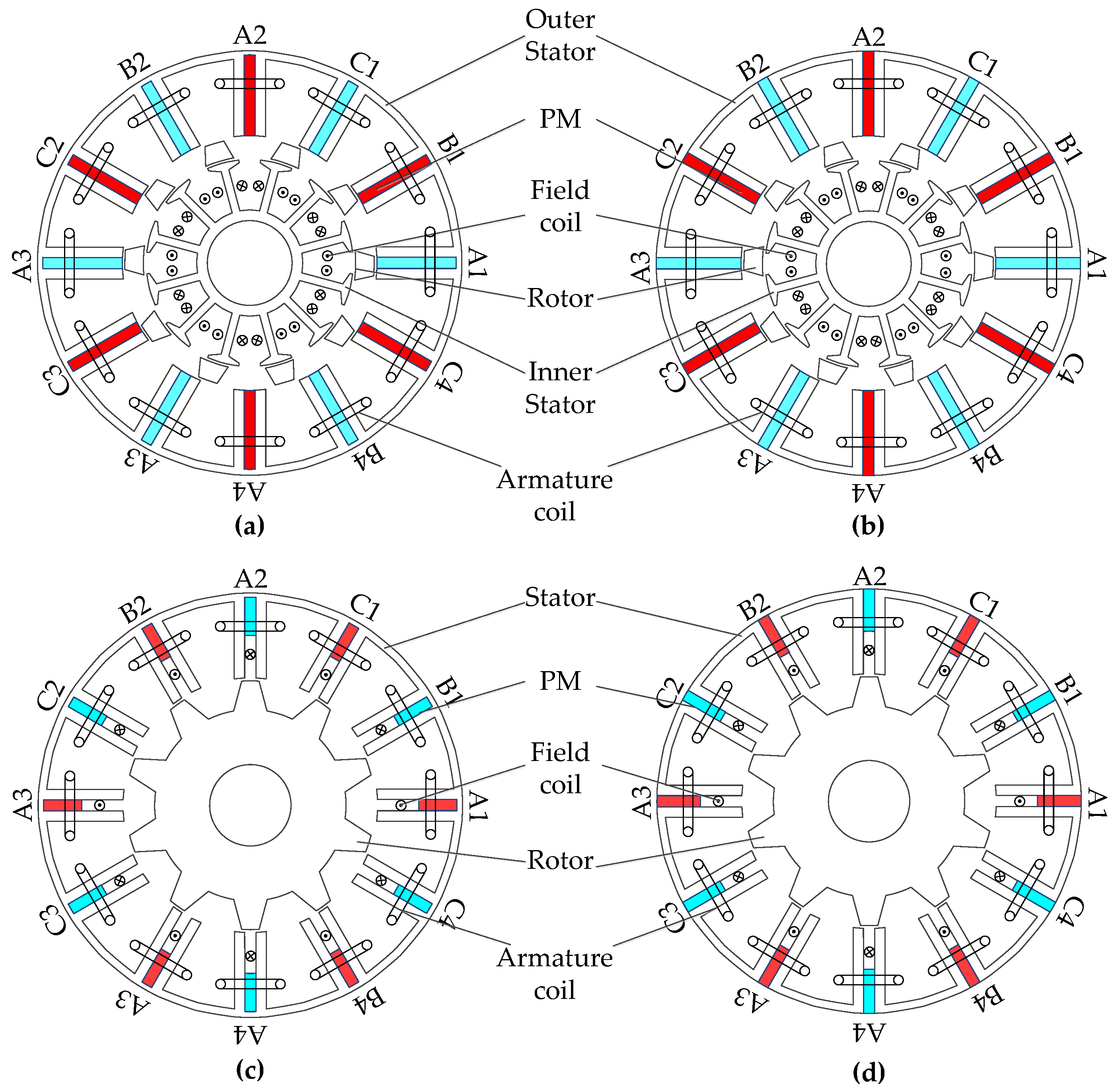
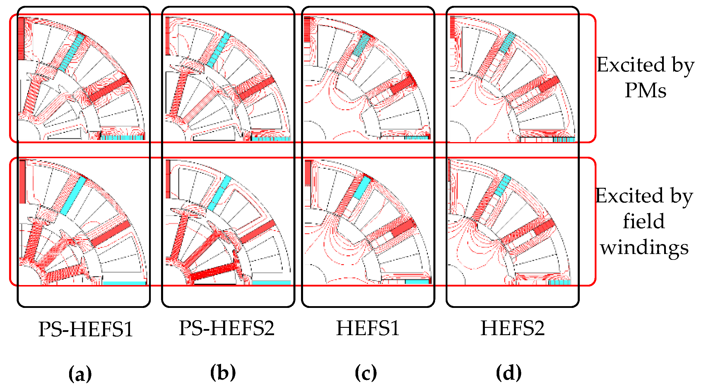
Both considering machine configurations with and without iron bridges, four machines are developed from the PS-HEFS machine and the conventional HEFS machine with single stator, namely the PS-HEFS machines with and without iron bridges, respectively named PS-HEFS1 and PS-HEFS2, and the HEFS machines with and without iron bridges, respectively named HEFS1 and HEFS2. As shown in Figure 1, the PS-HEFS machines are composed of an outer stator, an inner stator and a segmental rotor sandwiched between two stators. The tooth-slot structure is employed in inner stator, so that field windings can be wound around the inner stator teeth and the outer stator is exactly the same with that of conventional FSPM machines. Compared with existing HEFS machines, the field windings are set in the inner stator, so the inner space of machine rotor can be sufficiently utilized, and the conflict of location space among three electromagnetic sources can be relieved. Consequently, the magnetic field regulation capability can be increased. Furthermore, non-overlapping concentrated winding can be adopted for both of the armature and field windings, so that the copper reduction and relatively higher efficiency can be achieved.
Compared with PS-HEFS2 and HEFS2, iron flux bridges are employed between the adjacent U-shaped outer stator cores in PS-HEFS1 and HEFS1, resulting in an unsegmented outer stator lamination to facilitate the manufacture. On the other hand, the iron flux bridges provide additional magnetic circuit for the magnetic field, thus parallel magnetic paths can be achieved for PM magnetic field and excited field to enhance the magnetic field regulation capability, namely a flexible magnetic field adjustment can be achieved by a low magnetomotive force (MMF) of DC excitation.
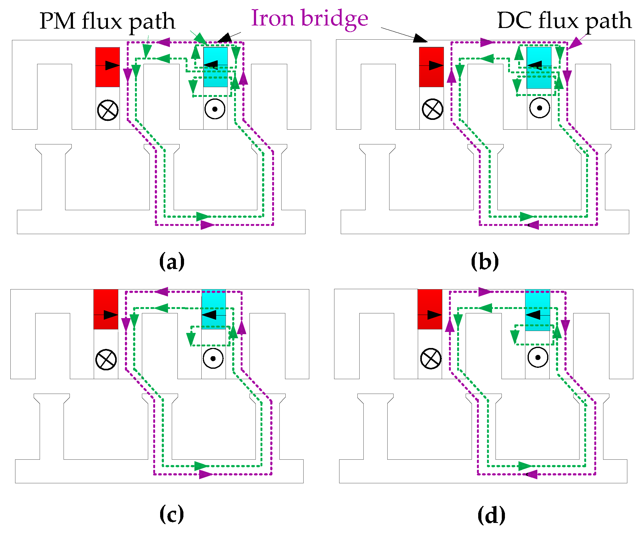
Figure 2 and Figure 3 illustrate the operation principles of PS-HEFS machines and HEFS machines with wound field excitations in opposite directions, in which the green lines and the purple lines represent the PM and wound field fluxes, respectively. It can be seen that the HEFS machines with and without iron flux bridges respectively show similar operation principles and flux paths with PS-HEFS machines with and without iron flux bridges. So, in this section, more attention and analysis are focused on the principles of PS-HEFS machines.
In Figure 2a,b, both main PM fluxes and wound field fluxes flow from the outer stator to the first rotor pole, then pass through the inner stator and return back to the outer stator by the second rotor pole. On the one hand, two parallel branches exist for PM fluxes due to the adoption of iron flux bridges, namely, path I with fluxes across iron flux bridges and path II with that passing through air-gap and rotor, and they are completely separate from each other. Thus, part of PM fluxes are shorted by iron flux bridges through path I, and most of the total PM magnetic field fluxes are along with path II, constituting the main air-gap PM magnetic field. On the other hand, the DC excitation fluxes pass through iron flux bridges in Figure 2a,b rather than through PMs in Figure 2c,d.
Consequently, the resultant magnetic field in air-gap is contributed by PM field and wound field together and it can be flexibly regulated with different DC currents, so enlarged CPSR can be achieved easily [22]. Moreover, the saturation degree in iron flux bridges is changed with different excitations, so varied regulation capabilities can be obtained in flux-enhancing operation and flux-weakening operation.
As can be seen, the iron flux bridge saturation makes considerable influence upon the electromagnetic performances, especially the flux regulation capability. So an equivalent lumped parameter magnetic circuit model is developed to illustrate the effects of iron flux bridges.
The following assumptions are made to simplify the derivation:
- ⧫
- The permeability of iron core is infinite except that of iron flux bridges, which is assumed to be unchanged with the rotor rotation and the variation of excitation sources.
- ⧫
- Finite coercivities are ignored.
- ⧫
- The variation of magnetic field is in the radial direction only.
Figure 4 shows the magnetic circuit of PS-HEFS machines with and without iron flux bridges, where Fdc and Fpm are the magnetomotive forces of field windings and PMs, respectively; Ppm, Pmb and Pg are the permeance of PMs, iron flux bridges, and air-gap, respectively; and ϕδ is the air-gap flux. With PMs excited only, namely Fdc = 0, the air-gap flux is
and the total air-gap flux due to PMs and wound field are
in which ϕδPM is the air-gap flux due to PMs and the subscripts of 1 and 2 represent machines with and without iron bridges. It should be mentioned that the direction of Fdc is decided by the direction of excitation current. So, the maximum flux ϕδmax and the minimum flux ϕδmin in air-gap under flux enhancing and flux weakening operations, respectively, can be obtained when the peak currents in different directions are fed into field windings.
The flux regulation ratio γ is defined as
So, the flux regulation ratios of two machines can be calculated as
Four conclusions can be obtained based on the equivalent magnetic circuit analysis.
- ⧫
- Due to the adoption of PS configuration, the magnetomotive force of excitation field can be enhanced, and resulting in improved flux regulation ratio.
- ⧫
- The PS-HEFS machine with iron bridges shows better flux regulation ratio than that without iron bridges.
- ⧫
- The flux regulation ratio γ will be increased with the enhancement of iron bridge permeance Pmb. Namely, it can be improved by adopting thicker iron bridges under the same MMF of field windings.
- ⧫
- The PM torque output capability will be reduced with the increase of Pmb due to the short circuit of PM magnetic field.
In summary, the CPSR can be enlarged due to the adoption of iron bridges and PS structure, and the PS-HEFS machine with iron bridges is more suitable for wide speed range applications, such as electric vehicles.
3. Multilevel Design Optimization
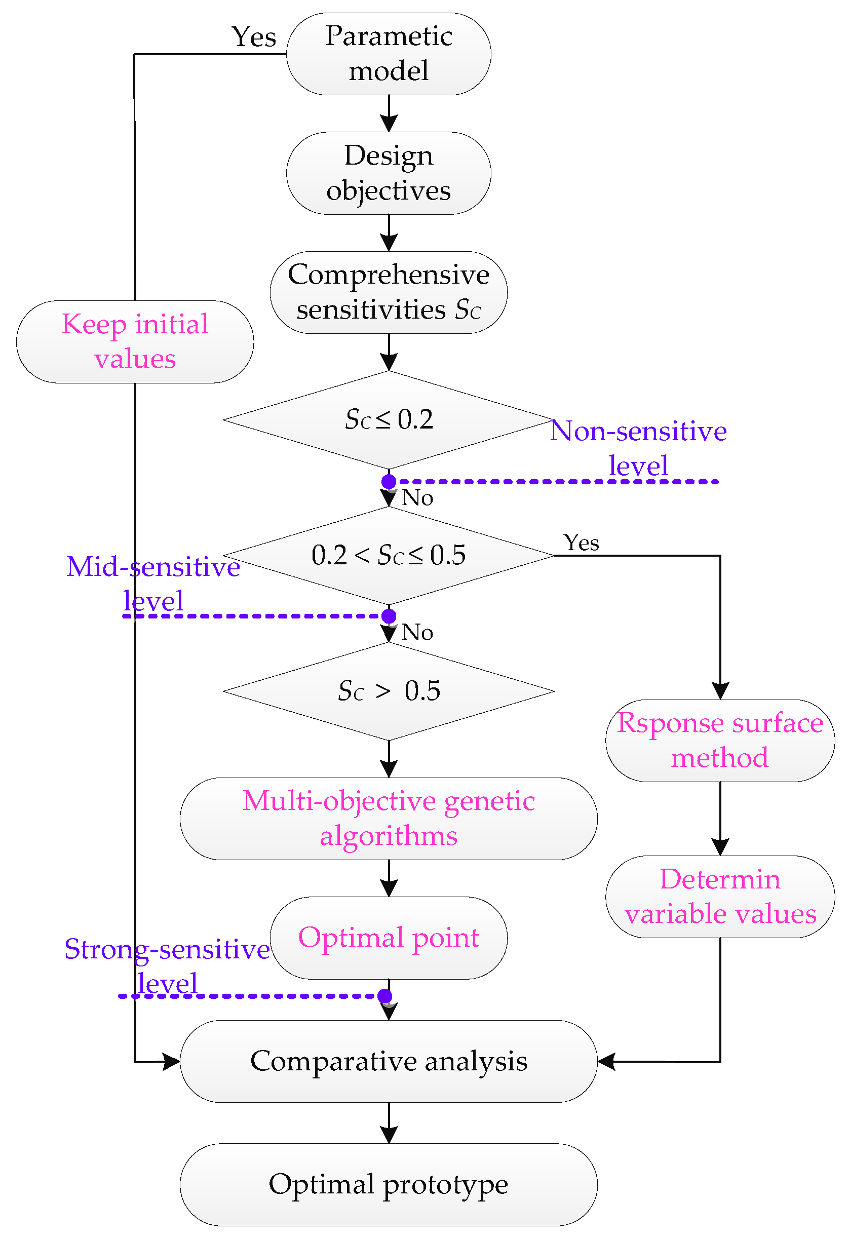
From the aforementioned analysis, PS-HEFS machines, especially with iron flux bridges, can exhibit better electromagnetic performances. To fairly compare these four machines in optimal conditions, optimization procedure is carried out. In Figure 5, parametric geometric models of PS-HEFS1 and HEFS1 are established to illustrate various design variables, and the PS-HEFS2 and HEFS2 can be respectively considered as special ones of PS-HEFS1 and HEFS1 with the thickness of iron bridges equaling zero. Apparently, it will be time-consuming when all design variables are optimized using conventional global optimization method. Therefore, in this section, multi-level design optimization [4] is adopted, in which all variables are classified into three levels according to different sensitivities. So the variable number in each level is significantly decreased, thus improving the design efficiency. Correspondingly, the multi-level design optimization process is depicted in Figure 6. It should be noted that because of similar optimization procedure, only the multi-level design optimization of PS-HEFS1 is presented in this paper, and the optimal values of all four machines will be listed together.
High torque output is one of the most important performance requirements for frequent acceleration and overload climbing operation, and wide CPSR (around 3–4 times the base speed) is also required for wide speed operation for electric vehicles [23]. Moreover, the torque ripple needs to be limited to an acceptable level for stably operating and comfortable seating. Thus the average torque T, flux regulation ratio γ, and cogging torque Tcog are determined to be main design objectives considering the low total harmonic degree of back-EMF.
Since each design variable exhibits various sensitivities upon different optimization objectives, it is difficult to decide the specific value of a parameter based on its effect on each of the three optimization objectives. Thus, the comprehensive sensitivity SC is defined as
where ST, Sγ, and Scog are sensitivities of each variable upon average torque, flux regulation ratio, and cogging torque respectively. Moreover, λ1, λ2, and λ3 are weight coefficients of three objectives according to the importance degree in electrical vehicles, and they are separately selected to be 0.4, 0.3, and 0.3 [3].
Then, variable sensitivities are calculated and listed in Table 1. According to the comprehensive sensitivity SC, three levels of variables, namely, strong-sensitive variables, mid-sensitive variables and non-sensitive variables can be intuitively obtained based on specific ranges as shown in (6). Thus, multi-level design optimization is developed.
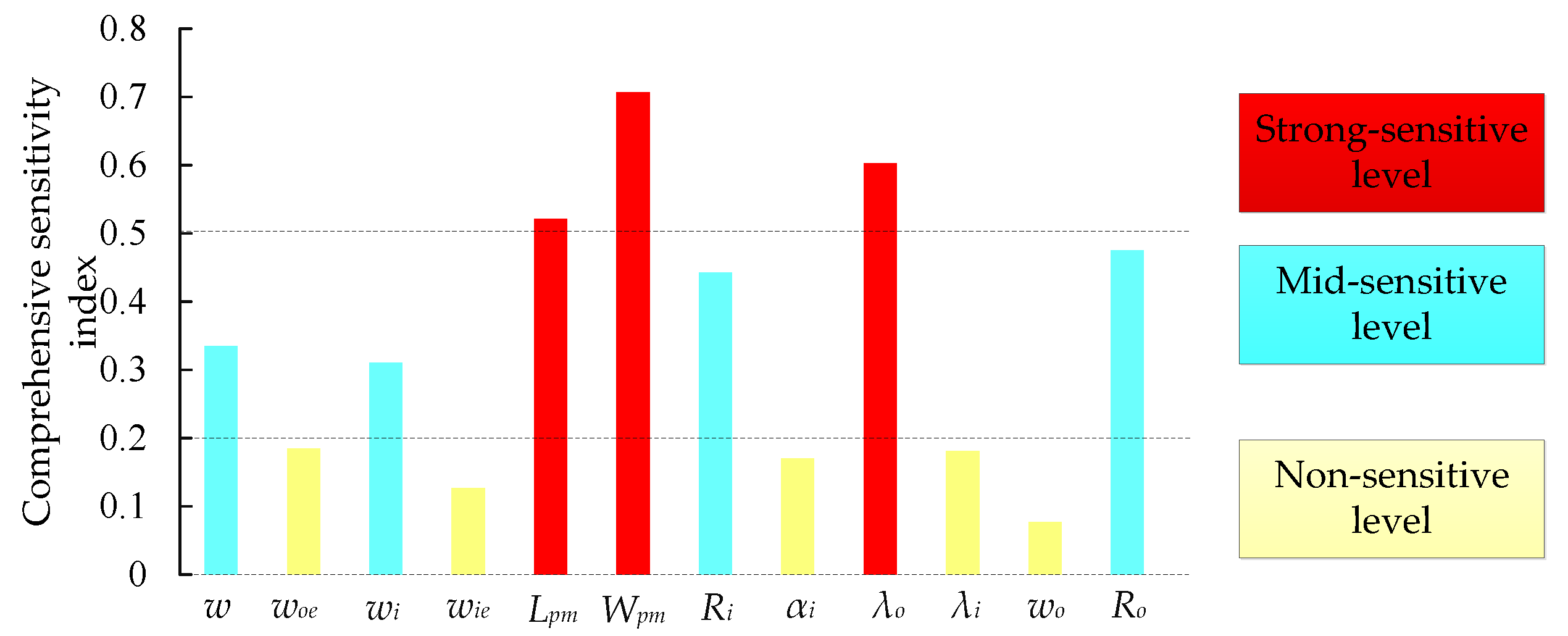
Figure 7 shows comprehensive sensitivities of each defined variable for PS-HEFS1. It can be seen that five variables are classified into the non-sensitive level, which means these variables exhibit little influence upon comprehensive design optimization, so the initial parameter values of them are fixed in the subsequent optimization process as shown in Table 2. In the mid-sensitive level, four variables are contained, indicating relatively considerable influence on the design objectives, and response surface (RS) optimization method is adopted for these variables’ optimization. Finally, three variables belong to the strong-sensitive level, which will be optimized by multi-objective genetic algorithm (MOGA) method in this paper.
A Mid-Sensitivity Level
The RS method generally possesses the advantages of efficient calculation and facilitating the establishment of design objective and variables, and the variation regularity between variables and design objectives can be obtained easily [24].Thus, in this section, the RS method is applied to conduct the optimization process of mid-sensitivity level.
Based on the RS theory, the response model of PS-HEFS machine can be expressed as
where u is the theoretical value of any design objectives, and N represents the number of design variables. Additionally, β is the regression coefficients, and x stands for the design variables.
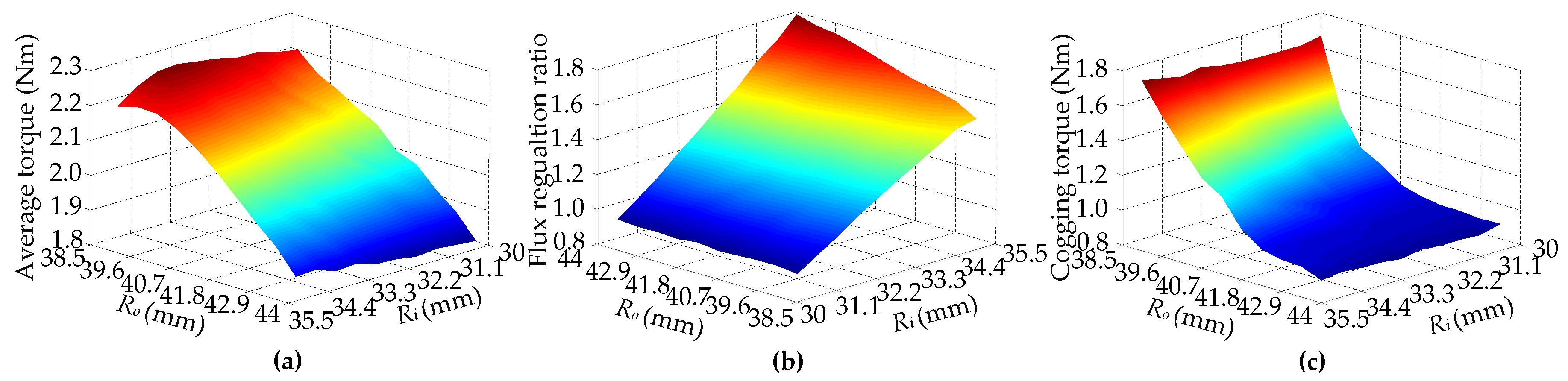
Figure 8 illustrates the surface plots of average torque, flux regulation ratio and cogging torque versus Ri and Ro calculated by RS method. As expected, the variation degrees are generally moderate, which is consistent with comprehensive sensitivity analysis aforementioned. In Figure 8a, the average torque declines apparently with the increase of Ro, because the ampere turns in outer stator slots are reduced correspondingly. Meanwhile, the average torque increases slowly with the enhancement of Ri, which shows a relatively little influence of Ri on average torque. In Figure 8b, the flux regulation ratio γ decreases steadily with the reduction of Ro, and improves apparently with higher MMF of DC field by enlarging inner stator radius Ri, so Ri is preferable to be designed as large as possible. From Figure 8c, it can be seen that the cogging torque decreases obviously in the initial stage of the increase of Ro then gradually stabilizes. Considering the compromise of required objectives, magnetic coupling and actual manufacture, the outer stator radius Ro and inner stator radius Ri are determined to be 42.93 mm and 35.83 mm, respectively.
Similarly, for intuitive presentation, three optimization objectives versus iron flux bridge thickness w and inner stator tooth width wi are illustrated in Figure 9. Along with the enhancement of iron flux bridge thickness w, it can be seen that the average torque declines significantly, but flux regulation ratio γ improves obviously, which commendably agrees with to the analysis in Section 2. Moreover, the cogging torque exhibits similar variation trend of average torque, mainly because of the change of magnetic field due to different w. Furthermore, inner stator teeth width wi shows little influence upon average torque and cogging torque, but dramatic effects on flux regulation ratio. Comprehensively considering all the factors, the iron bridges thickness w and inner stator width wi are chose to be 1.49 mm and 2.83 mm, respectively.
According to the similar operation principle and structure, the variable sensitivity and optimization procedure of remaining three machines can be carried out similarly, and the optimal parameters are listed in Table 3.
B Strong-Sensitivity Level
According to the adopted multi-level design optimization, there are three variables that contribute dramatic influence to design objectives. So, detailed analysis and coupling effects among multiple objectives and variables should be comprehensively considered.
The MOGA method is usually applied for automatic optimization based on the natural species evolution, in which various design objectives and variables, together with their mutual interactions, can be considered simultaneously, and thus leading to a series of optimal and intuitive optimization results. According to the coefficient of variation method, the general multi-objective mathematical model can be derived as
here f(x) represents the subfunction of design objectives, λ and k are the weight coefficient and number of design objectives, respectively.
To achieve the desired performance of the three design objectives and obtain relatively high efficiency of the seeking optimization, some constraints are derived.
Furthermore, to accurately reflect the variation trend, growth rates are chosen to be subfunction, so the corresponding objective function Hmin(f(x)) is defined as follows
in which f’(x) is the initial value of optimization objective, and the optimal point can be obtained when the minimum value of resultant function H is calculated.
Figure 10 shows the optimization results calculated by MOGA method, in which the optimal point, marked with red, exhibits the minimum resultant function value in (10), meaning relatively higher electromagnetic torque and flux regulation ratio and lower cogging torque. Thus, the tradeoff among three optimization objectives and mutual interactions can be well considered, and the corresponding values of initial and optimal models are listed in Table 2 and Table 3, respectively.
4. Comparison and Analysis
In this section, detailed analysis and comparisons of these four machines are conducted based on the optimal values. It should be mentioned that the outer diameter and stack length are identical in four machines.
Figure 11 shows the no-load magnetic field distributions of four machines with different excitations. Due to the adoption of iron bridges, some PM fluxes are shorted in PS-HEFS1 and HEFS1, and the winding field is parallel with PM magnetic field, so that the torque output will be reduced a little and the magnetic field regulation capability can be enhanced apparently compared with those of PS-HEFS2 and HEFS2.
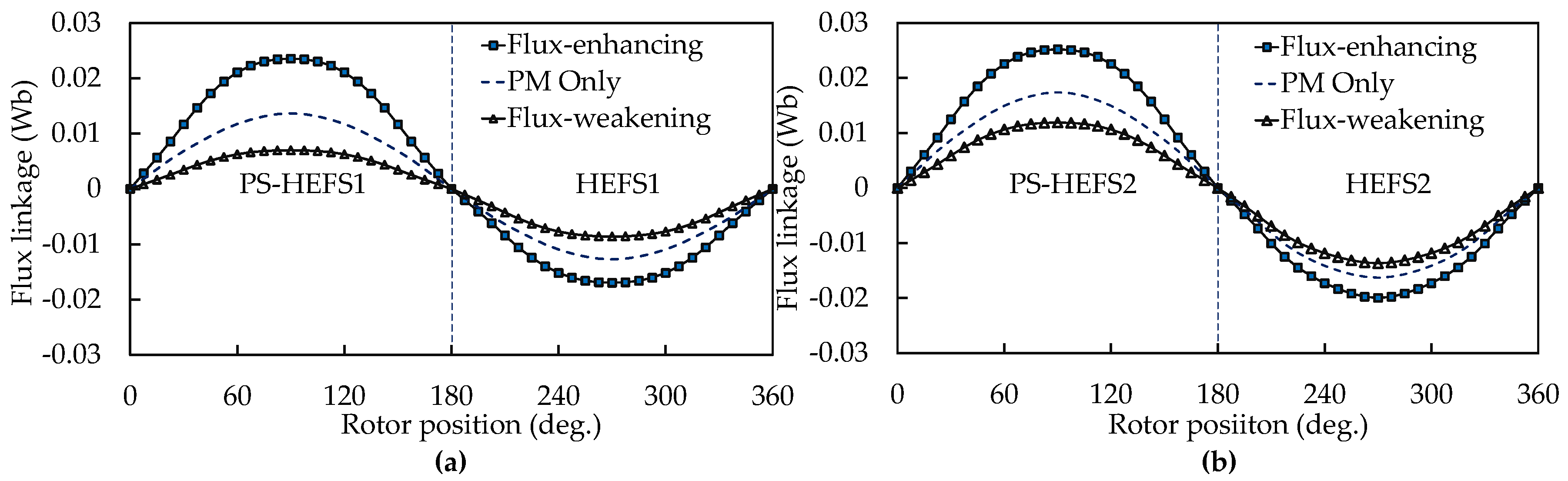
Figure 12 shows the flux linkage waveforms of four machines. It can be seen that PS-HEFS2 and HEFS1 respectively have the maximum and the minimum flux linkage peak values, and the flux regulation amplitudes of PS-HEFS1 and HEFS1 are higher obviously than those of the other two machines due to the adoption of iron bridges. Moreover, two PS-HEFS machines respectively possess higher flux regulation capabilities than two HEFS machines because of the larger field winding slot areas, thus allowing higher ampere-turn numbers. Furthermore, with excitation of flux-enhancing DC current, the PM magnetic field in iron flux bridges will be partly counteracted by positive wound field, resulting in decreased saturation in iron flux bridges, and thus magnetic circuit for wound field can be formed more easily. Meanwhile, the saturation degree will be enhanced by reversing the wound field direction. So these machines exhibit a higher regulation capability in flux-enhancing operation than that of flux-weakening operation.
Figure 13 shows torque performances with various current angles under the rated current for all machines. Apparently, the optimal current angle are all approximately closed to 0°, as marked by the vertical dashed line, so id = 0 control method is adopted in this paper to obtain the highest average torque.
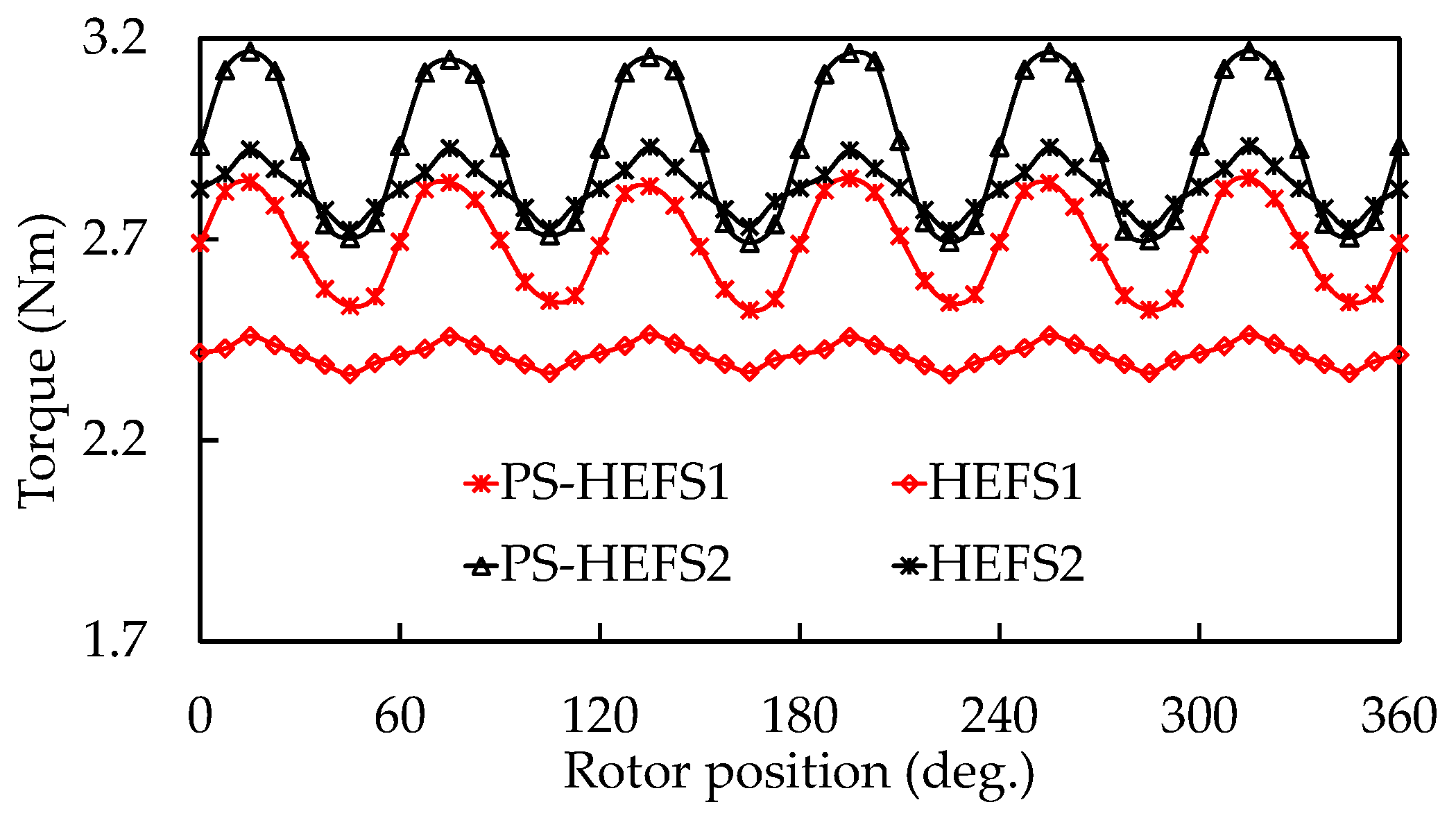
Figure 14 illustrates the predicted cogging torque waveforms of four machines without field current. It can be seen that the cogging torque peak values of two PS-HEFS machines are higher than those of two HEFS machines, because of the larger air-gap area caused by the PS structure and the higher PM usage. It can also be found that the cogging torques of machines with iron bridges are respectively smaller than those of the corresponding machines without iron bridges due to the existence of extra magnetic circuit. Figure 15 shows the torque waveforms of four machine without field winding excitation when the armature winding current Im = 13.8 A is fed using id = 0 control method. It can be seen that the average torque values of PS-HEFS1 and HEFS1 are lower than those of PS-HEFS2 and HEFS2, which is consistent with the analysis of flux linkages. Also, it can be found that the tendencies and peak-to-peak values of cogging torque are consistent with those of torque ripple. So it can be concluded that the PM torque ripple is mainly caused by the cogging torque.
Figure 16 illustrates the phase back-EMF waveforms with different field excitations, namely flux-enhancing, PM only, and flux-weakening. The labels of “Js = −5” and “Js = +5” represent the hybrid excitations of flux-weakening and flux-enhancing with the slot current density of 5 A/mm2 fed in the field winding. It can be seen that the back-EMF can be regulated effectively by adjusting the field winding current and the THD of back-EMF waveforms are always low. Furthermore, the PS-HESF machines exhibits a wider variation range of back-EMFs than the HEFS machines, and the peak back-EMF values of the machines with iron bridges are lower than those of the corresponding machines without iron bridges. It can be seen that the results have a good agreement with the flux linkage analysis.
The CPSR can be apparently extended under flux weakening operation, while the flux enhancing operation is beneficial to improve torque output and response speed in the low speed region. With the identical limitation of bus voltage, current density and wire size, the torque-speed curves of four machines are calculated by using the flux-linkage method [25]. As shown in Figure 17, the maximum torques of HEFS1 and PS-HEFS2 are the lowest and the highest, respectively, and both PS-HEFS machines can perform higher torques in flux enhancing operation. Furthermore, two PS machines possess wider CPSRs than those of two HEFS machines for increased excited fields, and PS-HEFS1 exhibits a wider CPSR than PS-HEFS2, which is corresponding to the analysis of PS structure and iron flux bridges. Also, it can be seen that the inflection points of four machines are different because the armature winding turn numbers in outer stator slots and the resultant air-gap flux density are varied, and thus resulting in changed back-EMF. So they will reach the same bus voltage limitation at different speed points.
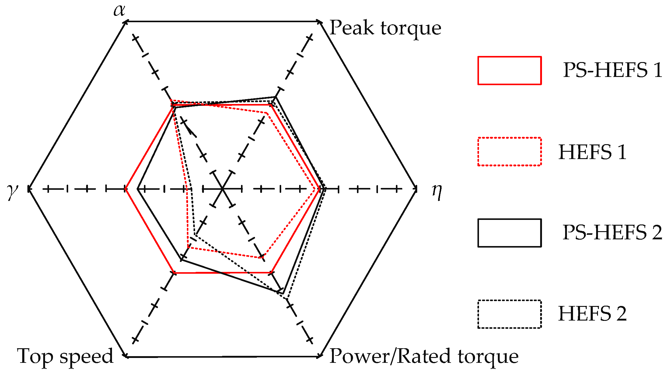
Furthermore, a quantitative comparison of the four machines is presented in Figure 18 in terms of six key performances, namely, peak torque, cogging torque level α, flux regulation ratio γ, top speed in the constant-power region, power/average torque and efficiency η, where the six key performances configures a hexagon and the HEFS1 is set as a regular hexagon for reference. The performances of other machines are normalized by the referenced values. Hence, the irregular pentagon shapes of the three cases can reflect the pros and cons of each topology. The detailed performances are listed in Table 4. The cogging torque level α is evaluated by
where the β refers to the peak-peak values of cogging torque. So, a bigger α indicates a smaller cogging torque.
The above analysis can be summarized as:
- Two PS-HEFS machines possess higher flux density regulation capabilities than two HEFS machines, because of the larger field winding slot areas, thus allowing a higher ampere-turn numbers.
- Two HEFS machines exhibit lower cogging torque due to the smaller air-gap areas and the lower PM MMF than those of two PS-HEFS machines.
- PS-HEFS1 and HEFS1 exhibit wider flux regulation ratio than corresponding machines without iron flux bridges, though their torques output is a little lower than that of PS-HEFS2 and HEFS2.
5. Conclusions
In this paper, four machines are derived according to the different stator structure and with and without iron flux bridges, namely, PS-HEFS1, PS-HEFS2, HEFS1, and HEFS2. In order to theoretically analyze the effect of PS structure and iron flux bridges, an equivalent lumped parameter magnetic circuit model is developed, it can be concluded that enlarged CPSR can be obtained by employing PS structure and iron flux bridges. Then, the multi-level design optimization method is adopted to obtain the optimal dimension parameters efficiently, so that all four machines can be compared in optimal condition. The simulation results reveal that the machines with PS structure exhibit higher torque density and flux regulation capability than conventional HEFS machine because of the sufficient utilization of inner space. Compared HEFS1 with PS-HEFS1 and HEFS2 with PS-HEFS2, the average torques are enhanced by 0.26 Nm and 0.13 Nm, respectively. Meanwhile, the flux regulation ratios are improved by 1.0 and 0.91, so that the top speeds are increased by 1500 rpm and 1300 rpm, respectively. By employing iron flux bridges, an extended CPSR can be obtained and the torque output will be reduced at the same time due to the leakage of PM magnetic field. Compared PS-HEFS2 with PS-HEFS1 and HEFS2 with HEFS1, the average torques are reduced by 0.29 Nm and 0.42 Nm, respectively. Moreover, the flux regulation ratios are improved by 0.17 and 0.08, and thus the top speeds are increased by 800 rpm and 600 rpm, respectively.
Author Contributions
Y.D. conceived of the idea of the research and provided guidance and supervision. W.L. is the main author of this manuscript who implemented the research and performed the analysis. Q.W., X.Z., and L.Q. provided some useful suggestions in the construction of this paper. All the authors have contributed significantly to this work.
Acknowledgments
This work was supported in part by Supports from the National Natural Science Foundation of China (grant nos. 51677081 and 51777089), the grant from the Priority Academic Program Development of Jiangsu Higher Education Institution, the Fund Program of Jiangsu University for Excellent Youth Teachers and Project 14JDG169.
Conflicts of Interest
The authors declare no conflict of interest.
References
- Du, Y.; Yang, G.; Quan, L.; Zhu, X.Y.; Xiao, F.; Wu, H.Y. Detent Force Reduction of a C-Core Linear Flux-Switching Permanent Magnet Machine with Multiple Additional Teeth. Energies 2017, 10, 318. [Google Scholar] [CrossRef]
- Du, Y.; Xiao, F.; Hua, W.; Zhu, X.Y.; Cheng, M.; Quan, L.; Chau, K.T. Comparison of flux-Switching PM motors with different winding configurations using magnetic gearing principle. IEEE Trans. Magn. 2016, 52, 8201908. [Google Scholar] [CrossRef]
- Xiang, Z.X.; Zhu, X.Y.; Quan, L.; Du, Y.; Zhang, C.; Fan, D.Y. Multilevel design optimization and operation of a brushless double mechanical port flux-switching permanent-magnet motor. IEEE Trans. Ind. Electron. 2016, 63, 6042–6054. [Google Scholar] [CrossRef]
- Zhu, X.Y.; Xiang, Z.X.; Zhang, C.; Du, Y.; Gu, W.W. Co-reduction of torque ripple for outer rotor flux-switching PM Mptor using systematic multi-level design and control schemes. IEEE Trans. Ind. Electron. 2017, 64, 1102–1112. [Google Scholar] [CrossRef]
- Shu, Z.M.; Zhu, X.Y.; Quan, L.; Du, Y.; Liu, C. Electromagnetic Performance Evaluation of an Outer-Rotor Flux-Switching Permanent Magnet Motor Based on Electrical-Thermal Two-Way Coupling Method. Energies 2017, 10, 677. [Google Scholar] [CrossRef]
- Zhu, X.Y.; Shu, Z.M.; Quan, L.; Xiang, Z.X.; Pan, X.Q. Design and multicondition comparison of two outer-rotor flux-switching permanent-magnet motors for in-wheel traction applications. IEEE Trans. Ind. Electron. 2017, 64, 6137–6148. [Google Scholar] [CrossRef]
- Zhu, D.H.; Shen, C.P.; Du, Y.; Ching, T.W. Comparison of a novel modular and complementary linear flux-switching permanent magnet motor with different phase arrangements. In Proceedings of the 2015 IEEE International Conference on Industrial Technology (ICIT), Seville, Spain, 17–19 March 2015; pp. 2636–2641. [Google Scholar]
- Hua, W.; Su, P.; Tong, M.H.; Meng, J.J. Investigation of a five-phase E-core hybrid-excitation flux-switching machine for EV and HEV applications. IEEE Trans. Ind. Appl. 2017, 53, 124–133. [Google Scholar] [CrossRef]
- Chau, K.T.; Chan, C.C.; Liu, C. Overview of permanent-magnet brushless drives for electric and hybrid electric vehicles. IEEE Trans. Ind. Electron. 2008, 55, 2246–2257. [Google Scholar] [CrossRef] [Green Version]
- Zhang, G.; Hua, W.; Cheng, M. Steady-state characteristics analysis of hybrid-excited flux-switching machines with identical iron laminations. Energies 2015, 8, 12898–12916. [Google Scholar] [CrossRef]
- Hua, W.; Cheng, M.; Zhang, G. Electromagnetic performance analysis of hybrid-excited flux-switching machines by a nonlinear magnetic network model. IEEE Trans. Magn. 2011, 47, 3216–3219. [Google Scholar] [CrossRef]
- Hoang, E.; Lecrivain, M.; Gabsi, M. A new structure of a switching flux synchronous polyphased machine with hybrid excitation. In Proceedings of the 2007 European Conference on Power Electronics and Applications, Aalborg, Denmark, 2–5 September 2007; pp. 1–8. [Google Scholar]
- Hua, W.; Cheng, M.; Zhang, G. A novel hybrid excitation flux switching motor for hybrid vehicles. IEEE Trans. Magn. 2009, 45, 4728–4731. [Google Scholar] [CrossRef]
- Owen, R.L.; Zhu, Z.Q.; Jewell, G.W. Hybrid excited flux-switching permanent magnet machines. In Proceedings of the 13th European Conference on Power Electronics and Applications (EPE ’09), Barcelona, Spain, 8–10 September 2009; pp. 1–10. [Google Scholar]
- Zhang, G.; Hua, W.; Cheng, M.; Liao, J.; Wang, K.; Zhang, J. Investigation of an improved hybrid-excitation flux-switching brushless machine for HEV/EV applications. IEEE Trans. Ind. Appl. 2015, 51, 3791–3799. [Google Scholar] [CrossRef]
- Owen, R.L.; Zhu, Z.Q.; Jewell, G.W. Hybrid-excited flux-switching permanent-magnet machines with iron flux bridges. IEEE Trans. Magn. 2010, 46, 1726–1729. [Google Scholar] [CrossRef]
- Chen, J.T.; Zhu, Z.Q.; Iwasaki, S.; Deodhar, R. A novel hybrid excited switched-flux brushless AC machine for EV/HEV applications. IEEE Trans. Veh. Technol. 2011, 60, 1365–1373. [Google Scholar] [CrossRef]
- Gaussens, B.; Hoang, E.; Lecrivain, M.; Manfe, P.; Gabsi, M. A hybrid-excited flux-switching machine for high-speed DC-alternator applications. IEEE Trans. Ind. Electron. 2014, 61, 2976–2989. [Google Scholar] [CrossRef]
- Evans, D.J.; Zhu, Z.Q. Novel partitioned stator switched flux permanent magnet machines. IEEE Trans. Magn. 2015, 51, 8100114. [Google Scholar] [CrossRef]
- Wang, Y.B.; Cheng, M.; Chen, M.; Du, Y.; Chau, K.T. Design of high-torque-density double-stator permanent magnet brushless motors. IET Electr. Power Appl. 2011, 5, 317–323. [Google Scholar] [CrossRef]
- Hua, H.; Zhu, Z.Q. Novel hybrid-excited switched-flux machine having separate field winding stator. IEEE Trans. Magn. 2016, 52, 8104004. [Google Scholar] [CrossRef]
- Yang, H.; Lin, H.Y.; Fang, S.H.; Huang, Y.K.; Zhu, Z.Q. High-performance partitioned-stator switched flux memory machines with hybrid magnets on external stator for traction applications. In Proceedings of the 2016 IEEE Energy Conversion Congress and Exposition (ECCE), Milwaukee, WI, USA, 18–22 September 2016; pp. 1–8. [Google Scholar]
- Zhu, Z.Q.; Howe, D. Electrical machines and drives for electric, hybrid, and fuel cell vehicles. Proc. IEEE. 2007, 95, 746–765. [Google Scholar] [CrossRef]
- Xiang, Z.X.; Quan, L.; Zhu, X.Y.; Huang, J.; Fan, D.Y. Investigation of Optimal Split Ratio in Brushless Dual-Rotor Flux-Switching Permanent Magnet Machine Considering Power Allocation. IEEE Trans. Magn. 2018, 54, 8102104. [Google Scholar] [CrossRef]
- Evans, D.J.; Zhu, Z.Q.; Zhan, H.L.; Wu, Z.Z.; Ge, X. Flux-weakening control performance of partitioned stator-switched flux PM machines. IEEE Trans. Ind. Appl. 2016, 52, 2350–2359. [Google Scholar] [CrossRef]
Figure 1.
Cross-sections of machines. (a) PS-HEFS1; (b) PS-HEFS2; (c) HEFS1; (d) HEFS2.

Figure 2.
Operation principle of PS-HEFS machine. (a) Flux enhancing, with iron bridges; (b) Flux weakening, with iron bridges; (c) Flux enhancing, without iron bridges; (d) Flux weakening, without iron bridges.
Figure 2.
Operation principle of PS-HEFS machine. (a) Flux enhancing, with iron bridges; (b) Flux weakening, with iron bridges; (c) Flux enhancing, without iron bridges; (d) Flux weakening, without iron bridges.

Figure 3.
Operation principle of HEFS machine. (a) Flux enhancing, with iron bridges; (b) Flux weakening, with iron bridges; (c) Flux enhancing, without iron bridges; (d) Flux weakening, without iron bridges.
Figure 3.
Operation principle of HEFS machine. (a) Flux enhancing, with iron bridges; (b) Flux weakening, with iron bridges; (c) Flux enhancing, without iron bridges; (d) Flux weakening, without iron bridges.

Figure 4.
Lumped parameter magnetic circuit models of PS-HEFS machines. (a) With iron bridges; (b) Without iron bridges.
Figure 4.
Lumped parameter magnetic circuit models of PS-HEFS machines. (a) With iron bridges; (b) Without iron bridges.

Figure 5.
Design variables parametric model. (a) PS-HEFS1; (b) HEFS1.

Figure 6.
Flowchart of multi-level design optimization.

Figure 7.
Sensitivity analysis for design objectives.

Figure 8.
RS optimization results. (a) Average torque versus Ro and Ri; (b) flux regulation ratio versus Ro and Ri; (c) cogging torque versus Ro and Ri.
Figure 8.
RS optimization results. (a) Average torque versus Ro and Ri; (b) flux regulation ratio versus Ro and Ri; (c) cogging torque versus Ro and Ri.

Figure 9.
RS optimization results. (a) Average torque versus w and wi; (b) Flux regulation ratio versus w and wi; (c) Cogging torque versus w and wi.
Figure 9.
RS optimization results. (a) Average torque versus w and wi; (b) Flux regulation ratio versus w and wi; (c) Cogging torque versus w and wi.

Figure 10.
Comprehensive optimization using MOGA method.

Figure 11.
No-load flux distributions of four machines with different excitations. (a) PS-HEFS1; (b) PS-HEFS2; (c) HEFS1; (d) HEFS2.
Figure 11.
No-load flux distributions of four machines with different excitations. (a) PS-HEFS1; (b) PS-HEFS2; (c) HEFS1; (d) HEFS2.

Figure 12.
Flux linkages of four machines. (a) PS-HEFS1 and HEFS1; (b) PS-HEFS2 and HEFS2.

Figure 13.
Variation of average torque versus current angle under with PM excitation.

Figure 14.
Predicted cogging torque waveforms.

Figure 15.
Predicted torque waveforms.

Figure 16.
Predicted back-EMF waveforms with different field excitations. (a) With iron flux bridges. (b) Without iron flux bridges.
Figure 16.
Predicted back-EMF waveforms with different field excitations. (a) With iron flux bridges. (b) Without iron flux bridges.

Figure 17.
Predicted T-n curve.

Figure 18.
Comparison of six key performances of the four machines.


Table 1.
Sensitivities for design variables
| Levels | Variables | Te | γ | Trip | SC |
|---|---|---|---|---|---|
| Non-sensitive level | Inner arc of rotor pole, λi | 0.34 | −0.11 | 0.04 | 0.181 |
| Outer stator yoke width, woe | −0.05 | −0.24 | 0.31 | 0.185 | |
| Outer stator tooth width, wo | 0.02 | 0.07 | −0.16 | 0.077 | |
| Inner stator yoke width, wie | 0.1 | −0.25 | 0.04 | 0.127 | |
| Arc of inner stator tooth tip, αi | 0.17 | −0.29 | −0.05 | 0.17 | |
| Mid-sensitive level | Thickness of iron bridge, w | −0.35 | 0.33 | −0.32 | 0.335 |
| Outer radius of Inner stator, Ri | −0.58 | 0.32 | −0.38 | 0.442 | |
| Inner stator tooth width, wi | 0.31 | −034 | 0.28 | 0.31 | |
| Inner radius of outer stator, Ro | −0.64 | 0.34 | −0.39 | 0.475 | |
| Strong-sensitive level | Outer arc of rotor pole, λo | −0.51 | 0.73 | −0.6 | 0.603 |
| PM length, Lpm | 0.65 | −0.46 | 0.41 | 0.521 | |
| PM width, Wpm | 0.68 | −0.81 | 0.64 | 0.707 |
Table 2.
Initial values of design variables
| Variables | Unit | PS-HEFS1 | HEFS1 | PS-HEFS2 | HEFS2 |
|---|---|---|---|---|---|
| Inner arc of rotor pole, λi | deg | 8.13 | 8 | 8.13 | 8 |
| Outer stator yoke width, woe | mm | 2.72 | 5.51 | 2.72 | 5.51 |
| Outer stator tooth width, wo | mm | 4.765 | 3.84 | 4.765 | 3.84 |
| Inner stator yoke width, wie | mm | 5 | - | 5 | - |
| Arc of inner stator tooth tip, αi | deg | 19.6 | - | 19.6 | - |
| Thickness of iron bridge, w | mm | 0.77 | 1 | - | - |
| Outer radius of Inner stator, Ri | mm | 34.74 | 31.1 | 34.74 | 31.1 |
| Inner stator tooth width, wi | mm | 4.16 | - | 4.16 | - |
| Inner radius of outer stator, Ro | mm | 41.49 | 37.5 | 41.49 | 37.5 |
| Outer arc of rotor pole, λo | deg | 11.77 | 4 | 11.77 | 4 |
| PM length, Lpm | mm | 21.74 | 12.2 | 19.87 | 13.2 |
| PM width, Wpm | mm | 3.5 | 4 | 3.5 | 4 |
Table 3.
Optimal values of design variables
| Variables | Unit | PS-HEFS1 | HEFS1 | PS-HEFS2 | HEFS2 |
|---|---|---|---|---|---|
| λi | deg | 8.84 | 9.9 | 7.28 | 9.86 |
| woe | mm | 1.2 | 5.51 | 3.15 | 5.1 |
| wo | mm | 4.54 | 3.84 | 4.42 | 3.93 |
| wie | mm | 4 | - | 4 | - |
| αi | deg | 18.66 | - | 23.94 | - |
| w | mm | 1.49 | 0.867 | - | - |
| Ri | mm | 35.83 | 32.2 | 39.16 | 32.3 |
| wi | mm | 2.86 | - | 3.77 | - |
| Ro | mm | 42.93 | 36.45 | 44.13 | 35.92 |
| λo | deg | 9.04 | 5.6 | 10.11 | 6.46 |
| Lpm | mm | 19.57 | 11.85 | 19.87 | 11.24 |
| Wpm | mm | 4 | 5.8 | 3.26 | 3.8 |
Table 4.
Key performances comparison among four machines
| Items | PS-HEFS1 | HEFS1 | PS-HEFS2 | HEFS2 |
|---|---|---|---|---|
| Average torque (Nm) | 2.67 | 2.41 | 2.96 | 2.83 |
| Power (W) | 280.3 | 228.8 | 346 | 379 |
| Cogging torque level | 0.057 | 0.023 | 0.067 | 0.036 |
| Flux regulation ratio | 1.6 | 0.6 | 1.43 | 0.52 |
| Top speed (r/min) | 5000 | 3500 | 4200 | 2900 |
| Iron loss (W) | 12.1 | 12.5 | 13.2 | 12.8 |
| Copper loss (W) | 31.2 | 28.8 | 31.4 | 30.5 |
| Efficiency (%) | 86.62 | 84.7 | 88.6 | 89.75 |
© 2018 by the authors. Licensee MDPI, Basel, Switzerland. This article is an open access article distributed under the terms and conditions of the Creative Commons Attribution (CC BY) license (http://creativecommons.org/licenses/by/4.0/).
Share and Cite
MDPI and ACS Style
Du, Y.; Lu, W.; Wang, Q.; Zhu, X.; Quan, L. Comparative Investigation of Hybrid Excitation Flux Switching Machines. Energies 2018, 11, 1428. https://doi.org/10.3390/en11061428
AMA Style
Du Y, Lu W, Wang Q, Zhu X, Quan L. Comparative Investigation of Hybrid Excitation Flux Switching Machines. Energies. 2018; 11(6):1428. https://doi.org/10.3390/en11061428
Chicago/Turabian StyleDu, Yi, Wei Lu, Qi Wang, Xiaoyong Zhu, and Li Quan. 2018. "Comparative Investigation of Hybrid Excitation Flux Switching Machines" Energies 11, no. 6: 1428. https://doi.org/10.3390/en11061428
Note that from the first issue of 2016, this journal uses article numbers instead of page numbers. See further details here.