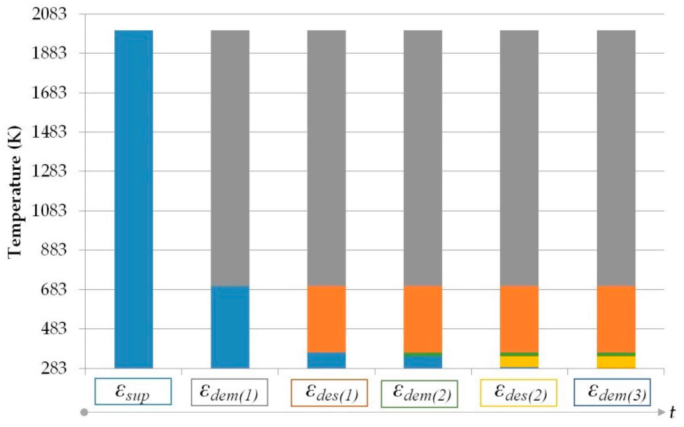
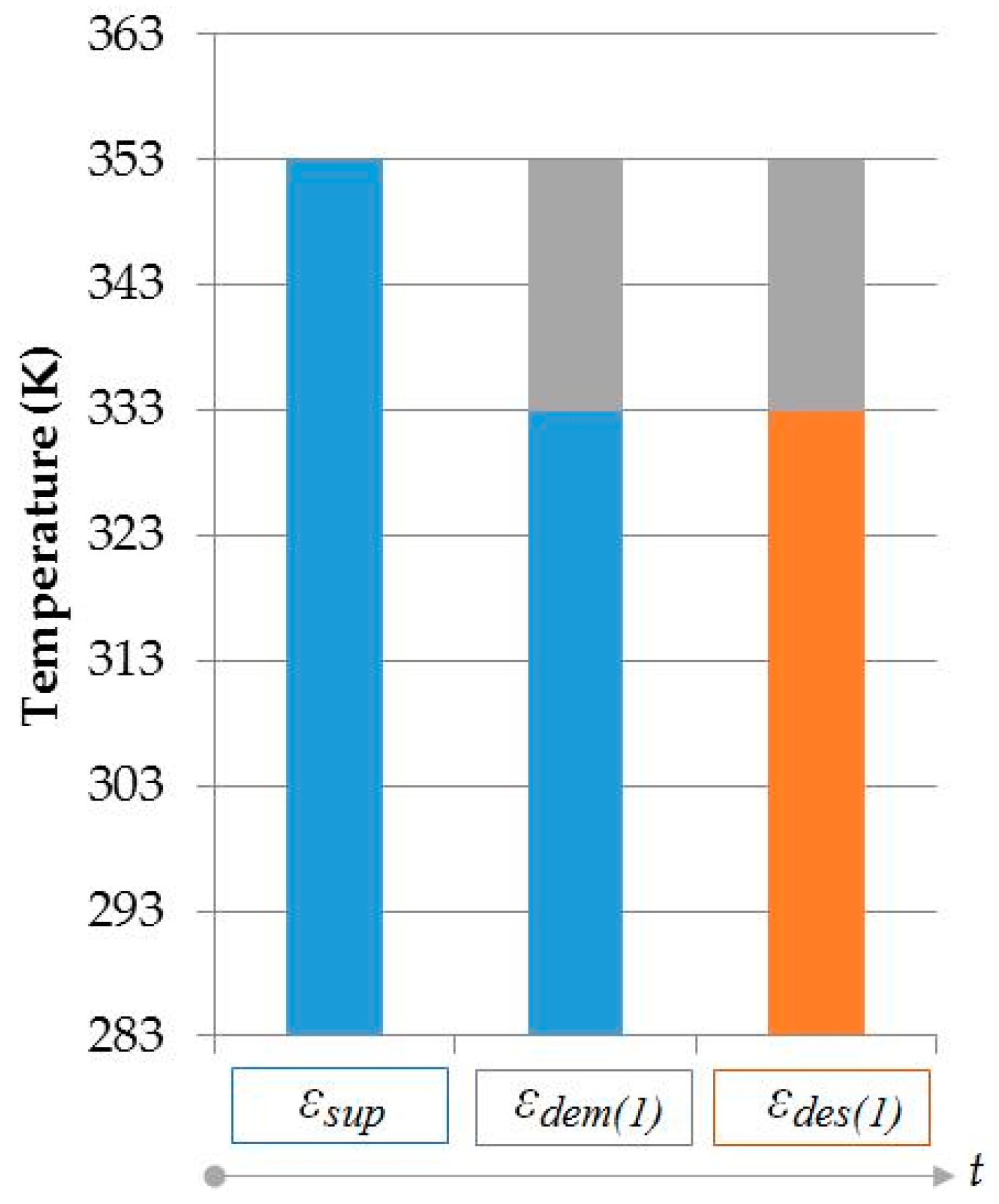
Figure 14 shows the Exergy Flow Bars [
42] for a baseline district energy (DE) system to which the hydrogen city model is compared. The baseline DE system uses natural gas with a combustion temperature of 2000 K while the reference environment temperature is 283 K. The available unit exergy (blue bars) is initially equal to
εsup that reduces at each proceeding application and point of exergy destruction. The first application is electricity production after which an alternating order of exergy destruction and applications at lower temperature levels take place for heat and cold production. The REMM Efficiency
ψR of the baseline DE system is calculated from Equation (10) as 0.25 based on two temperature intervals that represent points of exergy destruction. The values of the temperature intervals that determine
εdes(1) and
εdes(2) are given in
Table 2 that represent un-used temperature intervals between demanded applications. If the same system involves an additional steam generation process starting from 600 K and ending at 450 K, then the temperature interval for
εdes(1) will be split and reduce to (1 − 600 K/700 K) plus (1 − 365 K/450 K), which would increase the REMM efficiency only to 0.42. Exergy losses due to the pumping of any steam if generated and the hot and cold-water circulation in separate circuits in the district are not included in this value.
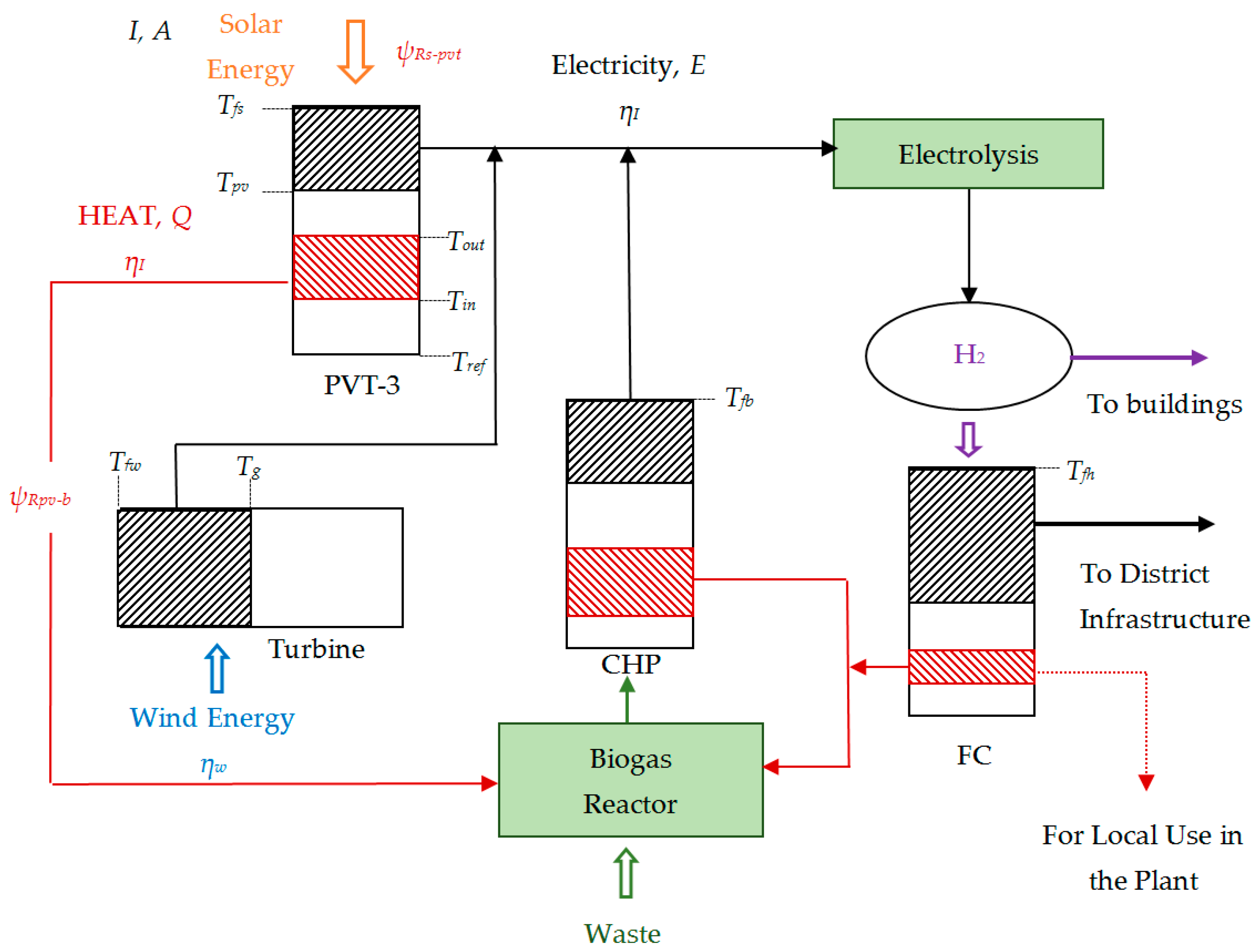
The baseline DE system that provides a basis of comparison is to be upgraded to a hydrogen city.
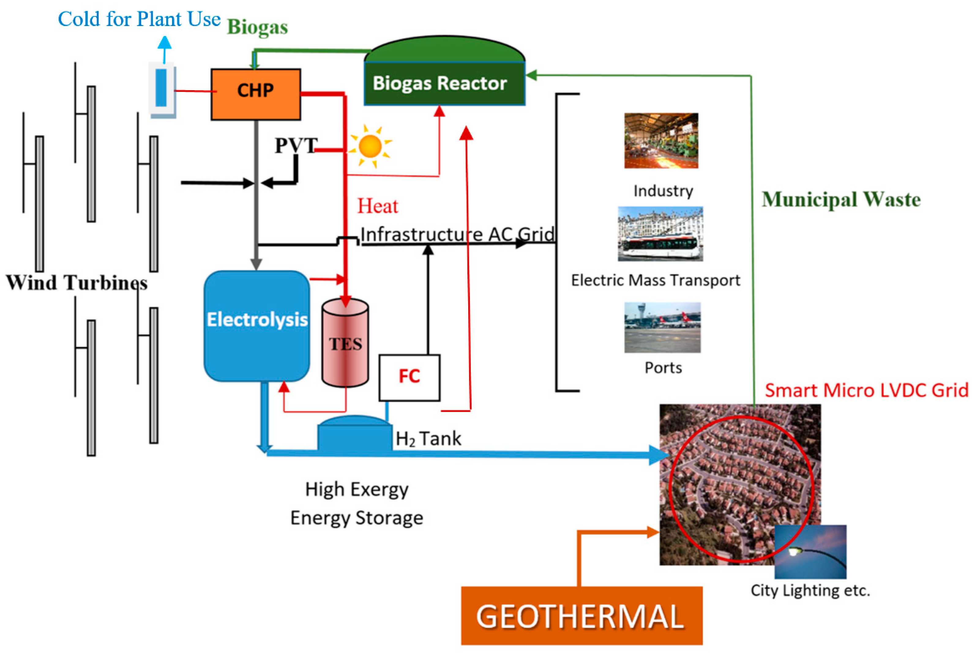
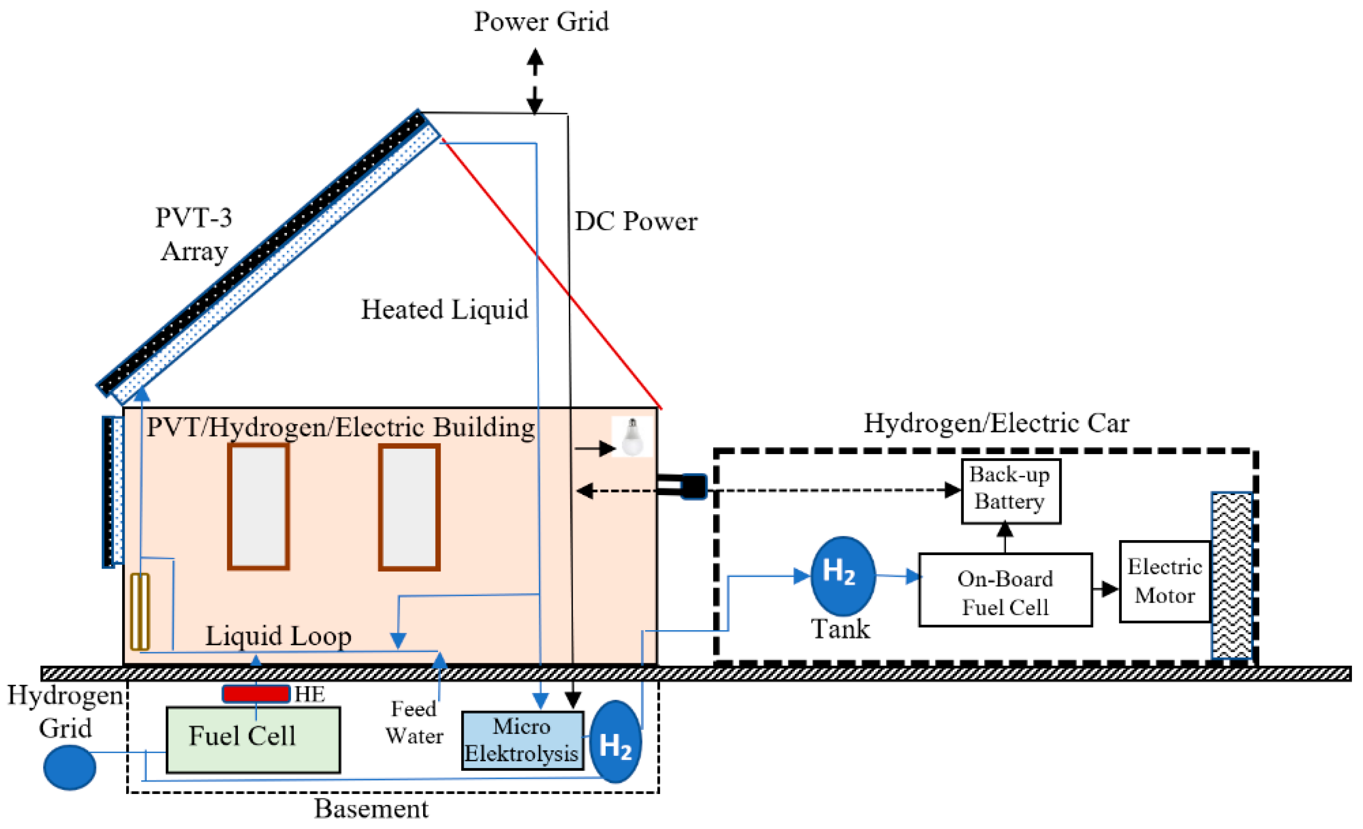
Figure 15 puts forth the linkages between the various components in providing exergy supply and useful applications. In the hydrogen city model, the circulation of hot and cold water and any steam is eliminated through the circulation of hydrogen gas, which is less energy intensive. In the upper left component of
Figure 15, solar energy is utilized in the PVT-3 system in the plant. First, DC electric power is generated in the PV modules. The heat that is absorbed by the PV coolant is utilized in the thermal charging of the biogas reactor. The exergy flow bar for a typical PVT-3 application at a solar insolation level of 600 W/m
2 is depicted in the form of the upper left bar in
Figure 15. Here, the Carnot cycle equivalent temperature for solar energy
Tfs is by definition the mapped equivalent source temperature for solar energy at a given insolation level
In as given by Equation (17) [
64]. This enables an exergy accounting with a more consistent boundary other than a Sun-Earth boundary.
4.3. Comparison with a Circular Geothermal Option
Low-enthalpy geothermal energy sources provide another option for the hydrogen city model if such resources exist in the vicinity (see previous
Figure 4). This option emerges from the fact that low-enthalpy geothermal energy sources have about a 30% share among different heat sources that drive ORC systems for electricity generation [
65]. The ORC market is rapidly increasing but their expansion is dependent on economic incentives, subsidies, and special tariffs [
65,
66]. For this reason, the ORC industry is reliant on the economic benefits of producing and selling electrical energy based on favorable conditions without considering the existing possibilities of improving exergy efficiency and acting upon the additional benefits of utilizing the available waste heat [
67].
Exergy analysis mainly focuses on the ORC operation and design without a holistic approach based on its connection between the energy source and demand points in the built environment. For example, Rowshanzadeh [
68] underlined the wide-ranging applications of ORC technology while pointing out the need for exergy analysis. Sun et al. [
69] investigated the suitable application conditions of ORC-Absorption Refrigeration Cycle (ARC) and ORC-Ejector Refrigeration Cycle (ERC) and compared results based on exergy analyses. Marini et al. [
70] analyzed an ORC system driven by solar energy with vacuum-tube collectors that provided electrical power for a building. The performance of different working fluids was simulated based on the objective of minimizing exergy destruction to conclude that ORC can be exergetically feasible given careful optimization.
Other studies that evaluated the benefits, risks, and potential disadvantages of ORC systems from a sustainability perspective indicate that ORC units may not be ecologically sound if used in a stand-alone format to generate only electric power [
67]. ORC systems need to be bundled with other renewable energy resources, systems, and energy storage units to be acceptable from an exergy point of view [
67]. From this perspective, exergy analyses can be used to quantify the advantages and disadvantages of using stand-alone ORC units versus different bundling alternatives with other renewable energy systems. Kılkış et al. [
53] indicated that the First Law of Thermodynamics is not sufficient to evaluate ORC systems for maximum performance and environmental sustainability. Different renewable energy systems and energy storage need to be bundled to form a hybrid system.
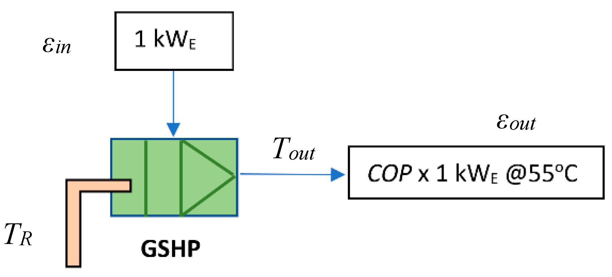
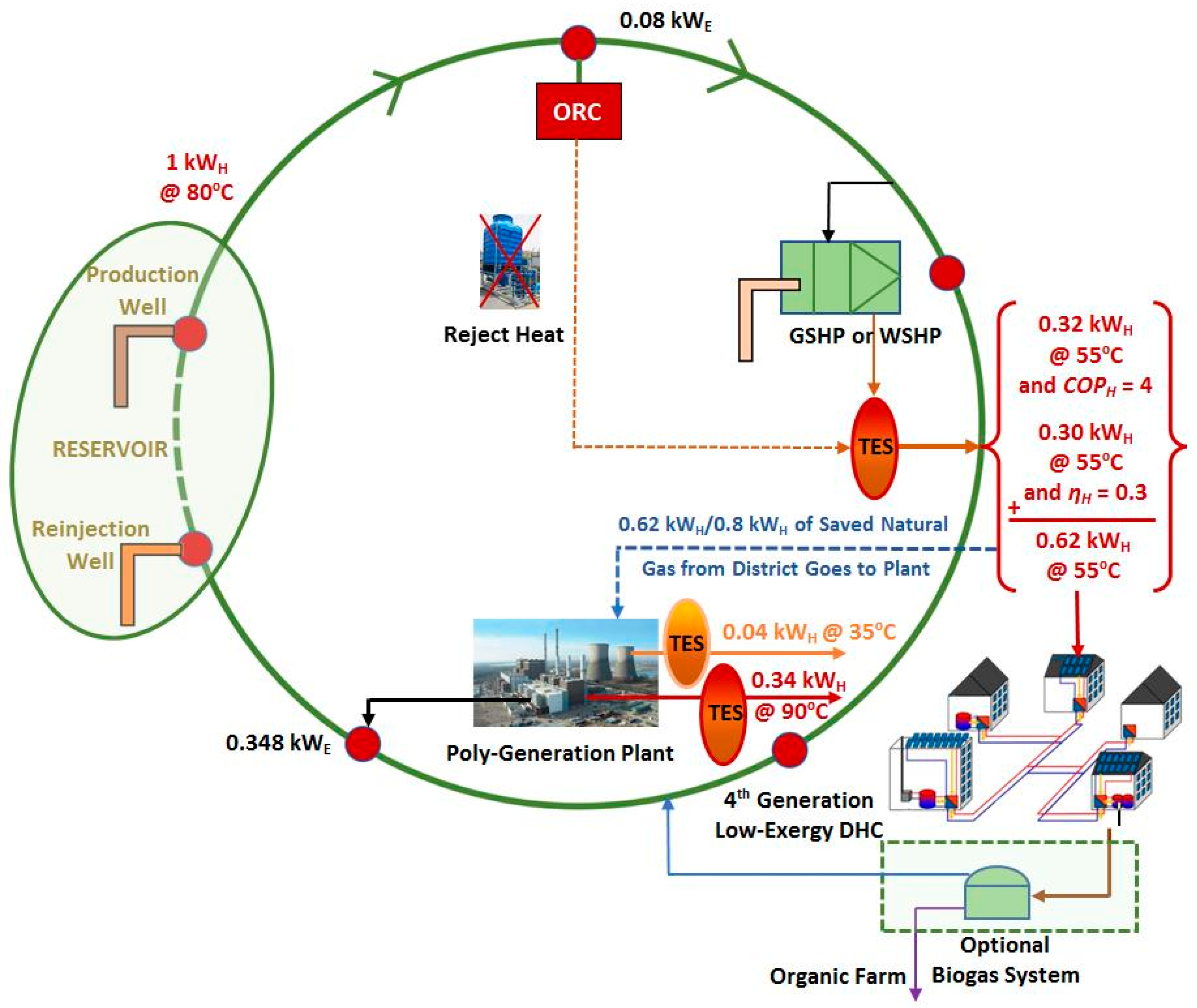
In this context, ground heat and geothermal energy is combined in a circular exergy flow to support the hydrogen city model. The option in heating mode is shown in
Figure 16 in which each unit power of geothermal energy at 80 °C is utilized in an ORC unit, which produces 0.08 kW
E that is used in a GSHP. The GSHP can generate 0.32 kW
H given that the average
COP is 4.0 at an output temperature of 55 °C in heating mode. This is coupled with the waste heat of the ORC at the same output temperature and directed to the district buildings in a local sub-district heating network.
If needed, the saved natural gas from the buildings’ previous on-site thermal systems is utilized in a poly-generation unit based on fuel cells. TES that are suited to two different levels of exergy are used to match the loads and shave-off peak loads. Electricity and additional high-exergy heat is generated at 90 °C for high-temperature applications in the district. In the cooling season, this heat may be used in absorption chillers for cold generation. From the geothermal production well to the re-injection well, the overall performance results are obtained as the total output. The three thermal power terms that include the later term at 35 °C for the preheating of DHW provides 1 kW
H.
In the case that the displaced natural gas, which was originally used in the district, is consumed internally in the fuel cell unit, then the gross
COP of the Circular Geothermal option becomes 1.348 based on 1 kW
H of geothermal thermal power input (Equation (24) and
Figure 16).
COP is greater than a value of one, since ground heat is utilized in the GSHP in addition to the geothermal energy.
Starting from a unit geothermal power at 80 °C (353 K), the Circular Geothermal option provides 0.348 kW
E and 1 kW
H at different supply temperatures. This output compares favorably with the 0.08 kW
E supplied by the ORC unit without reject heat recovery (see
Table 3) and 1 kW
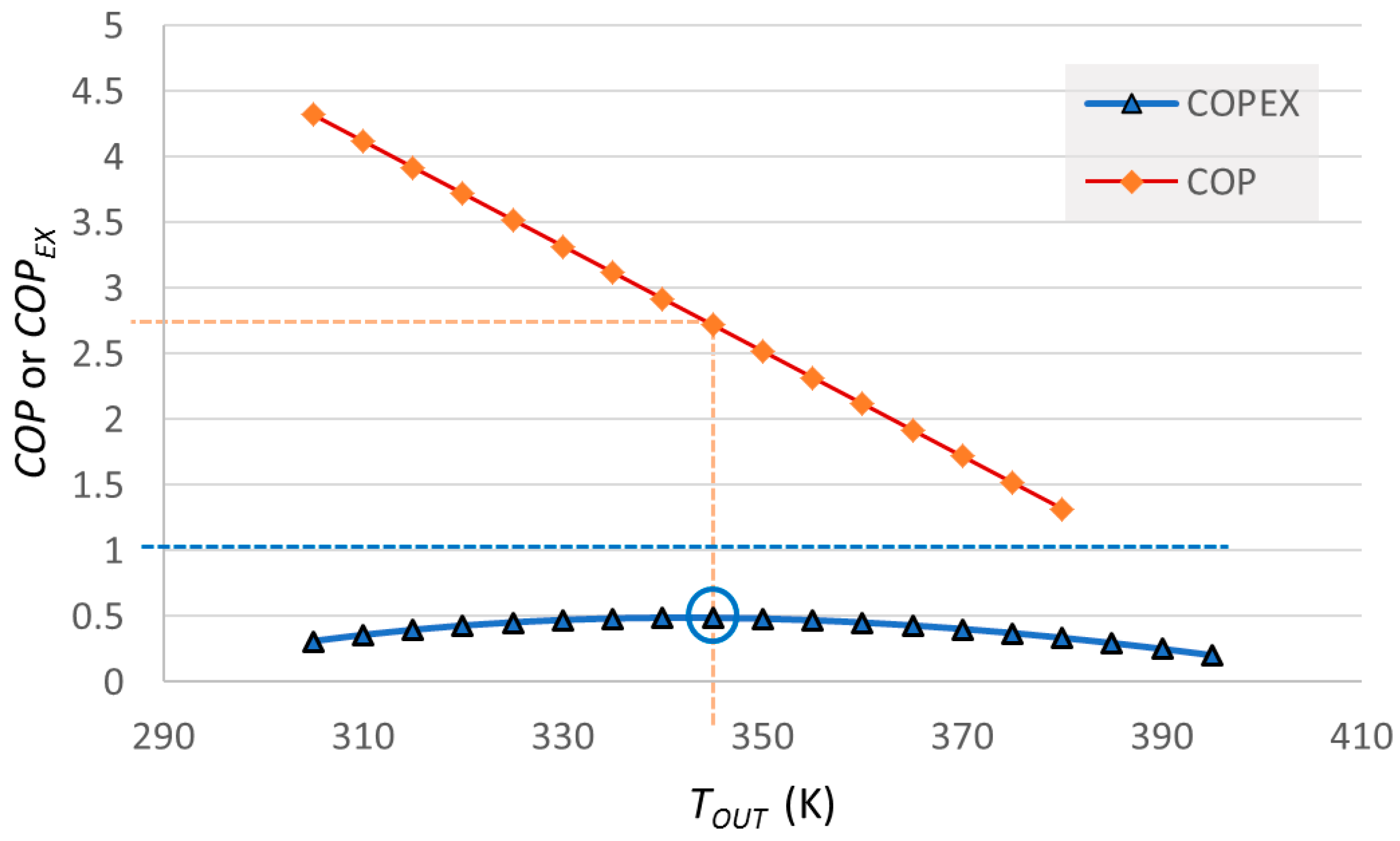
H at 80 °C supply if the geothermal power is utilized in the district in the form of heating only. In contrast, the above Equation (24) algebraically combines heat and power although their exergy values are quite different. While
COP is greater than one, this definition is misleading and requires the use of the
COPEx definition that considers the quality of the outputs as put forth in Equation (4).
In the above application of Equation (4), COPEX is the exergy-based COP for the entire cycle. All systems operate at constant base load. Optional solar and wind energy systems in the district contribute to peak loads with thermal storage. The grid is also acting for electrical energy storage at large. The entire collection of systems operates in a cascaded form, similar to a single, large-scale heat pump. If only an ORC unit would be used, then COPEX would be 0.092 and only 0.08 kWE would be generated. For this reason, the bundling of renewable energy systems can be warranted.
In some countries, including Italy, New Zealand, and Turkey, geothermal reservoirs are located in carbonate-rich rock grabens that contain calcium carbonate (CaCO
3). This means that geothermal wells extract CO
2 that needs to be recaptured, which is a rather expensive process. Consequently, most of the applications release CO
2 emissions into the atmosphere, nearly at a rate of 0.5 kg CO
2/kWh. In extreme cases, such as in the Menderes and Gediz grabens with high-enthalpy geothermal energy sources, the CO
2 emissions per kWh as
c is 0.9 to 1.3 kg/kWh that can be much higher than coal-based thermal plants [
71,
72]. If, however, a pumped binary power plant is used, then the emission factor is zero [
72]. An effective CO
2 capture and selection of the right technology are necessary if such reservoirs are to contribute favorably towards the aims of the Paris Agreement.
The Circular Geothermal option as shown in
Figure 16 comprises of geothermal production and re-injection wells, an ORC system, GSHP or water-source heat pumps (WSHP), a district energy distribution and collection system, a poly-generation system, and TES at different exergy levels. Such an option couples and mobilizes ground thermal energy and geothermal energy, including with the aim of displacing the use of natural gas in boilers for space heating in buildings. Instead, the displaced natural gas is used in the poly-generation plant with the generated electric power fed into the local grid. In distributed applications, the evaporator side of the heat pumps may be coupled to PV systems if this option is used in buildings to absorb the heat collected by the panels to improve the
COP of the GSHP. The flow rate needs to be dynamically optimized according to instantaneous solar insolation, heat demand, and other operating conditions to maximize the total exergy output (both power and heat) of the PVT system [
61,
62]. A biogas system that could be mixed with natural gas that is saved from the boilers and also provide organic fertilizer for local farming is optional.
The multiple outputs of the Circular Geothermal option surpass the outputs of conventional options. In this respect,
Figure 16 can be contrasted to options that have singular outputs, namely a DE system based on natural gas and the use of geothermal energy in ORC to produce only electricity. The integration that enables the multiplicity of outputs in
Figure 16 also provides for improvements in the value of
ψR. This is further valid if the Circular Geothermal option is compared to the direct use of geothermal energy for separate heat and power production. The direct use of geothermal energy for district heating (
Figure 17) and the direct use of geothermal energy for ORC power generation (
Figure 18) are compared based on Exergy Flow Bars as provided below.
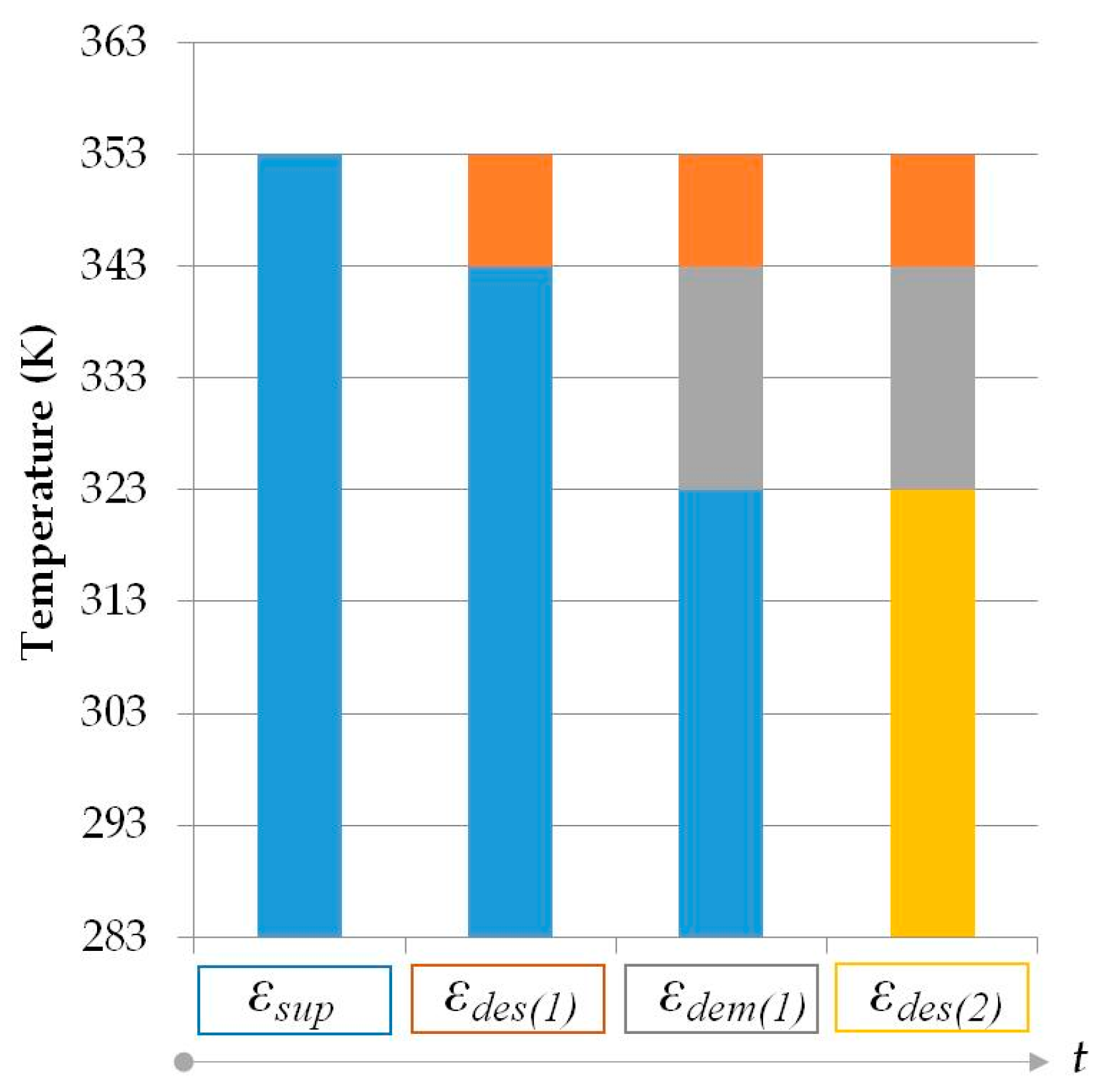
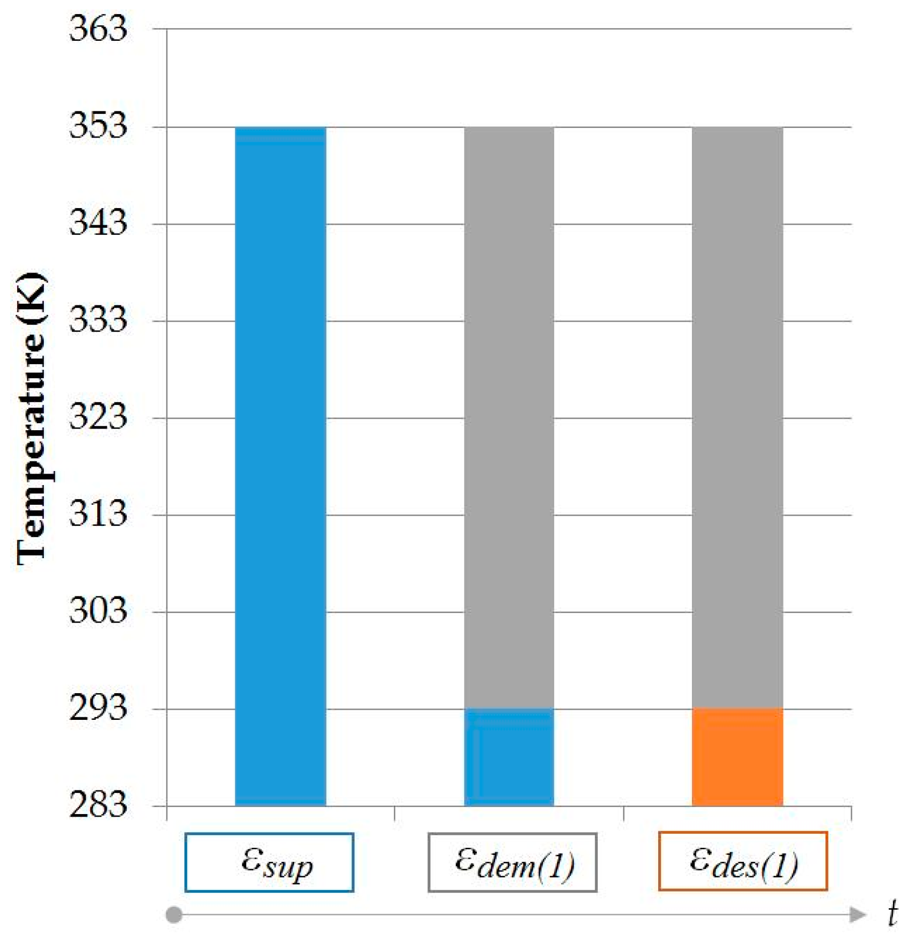
In
Figure 17 for the direct use of geothermal energy for district heating, exergy destruction takes place both upstream (
εdes(1)) and downstream (
εdes(2)) of energy usage. Since exergy is also destroyed upstream, Equation (11) is used for the REMM Efficiency
ψR based on an ideal Carnot cycle [
42]:
Here, εdem represents the demand exergy of the district heating system application between 70 °C (343 K) and 50 °C (323 K) for buildings that are connected to the system (see also Equation (11)). Another feature of the analysis is the ability to identify the exergetic match of the exergy supply with the final application. The final application is comfort heating at 20 °C indoor air temperature in buildings so that the εdem term is replaced by (1 − 283 K/293 K). In this case, ψR reduces to 0.172.
Figure 18 provides the Exergy Flow Bars for the ORC power generation case. The un-utilized thermal output of the ORC is taken at temperatures about 60 °C (333 K) onwards. Since practically no exergy destruction takes place upstream, Equation (10) is applied as given in Equation (27):
The resource temperature
Tf is the geothermal fluid temperature at the wellhead that is taken as 353 K also in
Figure 17,
Figure 18 and
Figure 19. If any fuel like biogas or natural gas is used, then this temperature is equal to the Adiabatic Flame Temperature (AFT). As previously defined, an equivalent temperature is put forth for solar, wind, and any other renewable energy resource without a direct
Tf value.
The primary characteristic of the Circular Geothermal option is that it represents an integrated, compound power and heat system at large. The option may be also applied to single buildings and scaled up to large district energy systems with possible integration with a hydrogen economy cycle. While most suitable for 4GDE, the Circular Geothermal option can be further applicable to district cooling applications. In this case, cold storage and absorption/adsorption units may be used.
The two options in
Figure 17 and
Figure 18 are further compared based on the
CR indicator as defined in Equations (15) and (16). From Equation (15), the values of
CR for geothermal district heating and power-only ORC options are 0.19 and 0.019, respectively. Here, the value of the net energy efficiency after parasitic losses
ηI is taken as 0.65 for district heating while it is taken as 0.08 for ORC.
The approach of
CR further reveals advantages when applied to the Circular Geothermal option for which the Exergy Flow Bars are provided below in
Figure 19. Other minor exergy destructions in heating are neglected. The respective values based on the application of Equation (10) are:
and from Equation (16):
After comparing the above results, the
CR values are further used to evaluate a CO
2 reduction potential ratio
R according to REMM [
38]. Equation (30) compares the geothermal district heating only case with
CR = 0.19 and the Circular Geothermal option with
CR = 1.114. A similar comparison with the power-only ORC case with
CR = 0.09 indicates 2.15 times higher CO
2 reduction potential. The degree of improvement increases with the geothermal reservoir temperature and applications.


