Article

A Reconfigurable Mesh-Ring Topology for Bluetooth Sensor Networks

1
Zhejiang Industry & Trade Vocational College, Wenzhou 325000, China
2
Department of Electronics Engineering, Chung Hua University, Hsinchu 30012, Taiwan
*
Author to whom correspondence should be addressed.
Energies 2018, 11(5), 1163; https://doi.org/10.3390/en11051163
Submission received: 2 April 2018 / Revised: 28 April 2018 / Accepted: 2 May 2018 / Published: 7 May 2018
(This article belongs to the Special Issue Wireless Sensor Networks, Internet of Things and Smart Residential)

Abstract

:
In this paper, a Reconfigurable Mesh-Ring (RMR) algorithm is proposed for Bluetooth sensor networks. The algorithm is designed in three stages to determine the optimal configuration of the mesh-ring network. Firstly, a designated root advertises and discovers its neighboring nodes. Secondly, a scatternet criterion is built to compute the minimum number of piconets and distributes the connection information for piconet and scatternet. Finally, a peak-search method is designed to determine the optimal mesh-ring configuration for various sizes of networks. To maximize the network capacity, the research problem is formulated by determining the best connectivity of available mesh links. During the formation and maintenance phases, three possible configurations (including piconet, scatternet, and hybrid) are examined to determine the optimal placement of mesh links. The peak-search method is a systematic approach, and is implemented by three functional blocks: the topology formation block generates the mesh-ring topology, the routing efficiency block computes the routing performance, and the optimum decision block introduces a decision-making criterion to determine the optimum number of mesh links. Simulation results demonstrate that the optimal mesh-ring configuration can be determined and that the scatternet case achieves better overall performance than the other two configurations. The RMR topology also outperforms the conventional ring-based and cluster-based mesh methods in terms of throughput performance for Bluetooth configurable networks.

1. Introduction

Bluetooth is currently one of the most promising available ad hoc wireless technologies [1,2,3,4], and the introduction of its advantageous features is considered to be one of the main enablers of the Internet of Things (IoT) [5,6,7,8,9,10]. Until now, Bluetooth Low Energy (BLE) technology [11] has been embedded in existing mobile and portable devices, offering the advantages of short-range radio, low power, and low cost wireless connectivity. At present, there is wide use of smart devices, such as smart phones, tablets and laptops connected to multi-hop networks through BLE devices. BLE data applications are increasingly emerging in daily life, such as in health networks [12], industry automation [13], wireless sensor networks [14], etc. However, these applications pose some important research challenges, such as how to connect BLE devices in order to share information between users, and how to form the desired network configurations for various types of applications.
The main feature of BLE version 4.1 is that nodes can play dual roles as relays, and such relay nodes can enable inter-piconet communications. The relay node design increases the possibility of implementing the scatternet formation algorithm and multi-hop routing for BLE devices.
To date, the development of multi-hop routing networks has faced some inherent challenges. The main technical challenges include research design issues with respect to the formation algorithms [15] and routing protocols [16,17]. The scatternet formation problem involves how to construct individual piconets and connect them together into a scatternet. On the other hand, the routing protocols deal with the problem of delivering messages efficiently in such a generated scatternet.
To construct a multi-hop ad hoc network, many scatternet formation algorithms have been developed; they can be classified into two categories. One category, the single-hop scenario [18,19], deals with the situations in which all nodes are within radio range. The other category, the multi-hop scenario [20,21,22] handles situations in which not all nodes are necessarily within radio range. In addition, a number of different topology models can be generated, according to the desired purpose of the scatternet.
Currently, most scatternet formation methods partition networks by collecting complete topology information, introducing considerable computation and communication overheads [23]. In general, the generating architectures can be classified as tree, ring and mesh topologies [24]. While the ring architecture is simple for proactive routing, it produces longer path lengths for packet transmission, especially when the size of the ring network increases. On the other hand, the mesh architecture reduces path length in terms of packet delay, but introduces larger formation complexity than other topologies.
In order to utilize the advantages of mesh-subnet and ring-subnet, this paper proposes a ring-based subnet with mesh interconnection, called the Reconfigurable Mesh-Ring (RMR), to construct a scatternet. RMR simultaneously considers scatternet formation and routing design issues to generate a configurable mesh-ring topology. RMR constructs a ring-shaped topology as a backbone subnet, which is then associated with a mesh-shaped topology. However, the placement of the available mesh connection is adjustable, so as to determine the optimal configuration with better throughput for various network sizes. To maximize network capacity, three configurations (including piconet, scatternet, and hybrid) are investigated to determine the optimal placement of the mesh links. In seeking to determine the optimum configuration, a heuristic peak-search method is presented in order to achieve the optimal placement of the available mesh links.
The remainder of this paper is arranged as follows: Section 2 proposes the motivation, mesh-ring formation algorithm, and routing algorithm to generate the desired topology. In Section 3, the problem formulation, reconfiguration mesh-ring topology, and peak-search method are presented to determine the optimal bridge for each link. In Section 4, the optimal configuration is determined and throughput performances are demonstrated via computer simulations. Finally, conclusions are drawn in Section 5.

2. Proposed Method

2.1. Motivation

Until now, the Bluetooth generating architectures can generally be classified as having line, tree, ring or mesh network topologies. While the ring architecture is simple and suitable for proactive routing, it produces longer path lengths for packet transmission, especially when the size of the ring network increases. The routing protocol on a larger ring subnet needs to consider the routing path length design issue to mitigate the packet delay since most previous studies consider one-way routing in the ring subnet [25,26].
On the other hand, the mesh architecture reduces path length in terms of packet delay performance, but introduces larger scatternet formation complexity than other topologies. Another important issue in a Bluetooth scatternet is routing with a formed scatternet. Current routing solutions for mesh networks, including proactive, the reactive, and hybrid algorithms, discuss protocol design without considering the ease of routing in such a scatternet. As a result, the routing protocol with formation design [27] is challenging, due to existing performance tradeoffs between formation complexity and packet delay.
In contrast to prior works on Bluetooth scatternet formation and routing algorithms, a RMR algorithm is designed to jointly address the problems of achieving the simple routing and determining the optimal placement of mesh links for a multi-hop scatternet. With local topology, a ring subnet is generated first and each master in the ring subnet forms its piconet individually. A peak-search method is then introduced in the formation phase to determine the optimal placement of available mesh links by interconnecting masters in the ring subnet, thus achieving better network capacity. Figure 1 illustrates an example of the RMR configuration that satisfies the design objectives to generate networks into desired mesh-ring subnets.

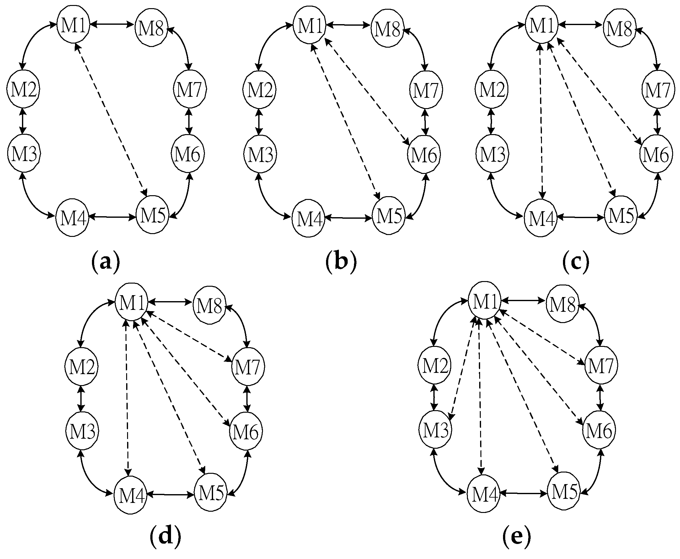
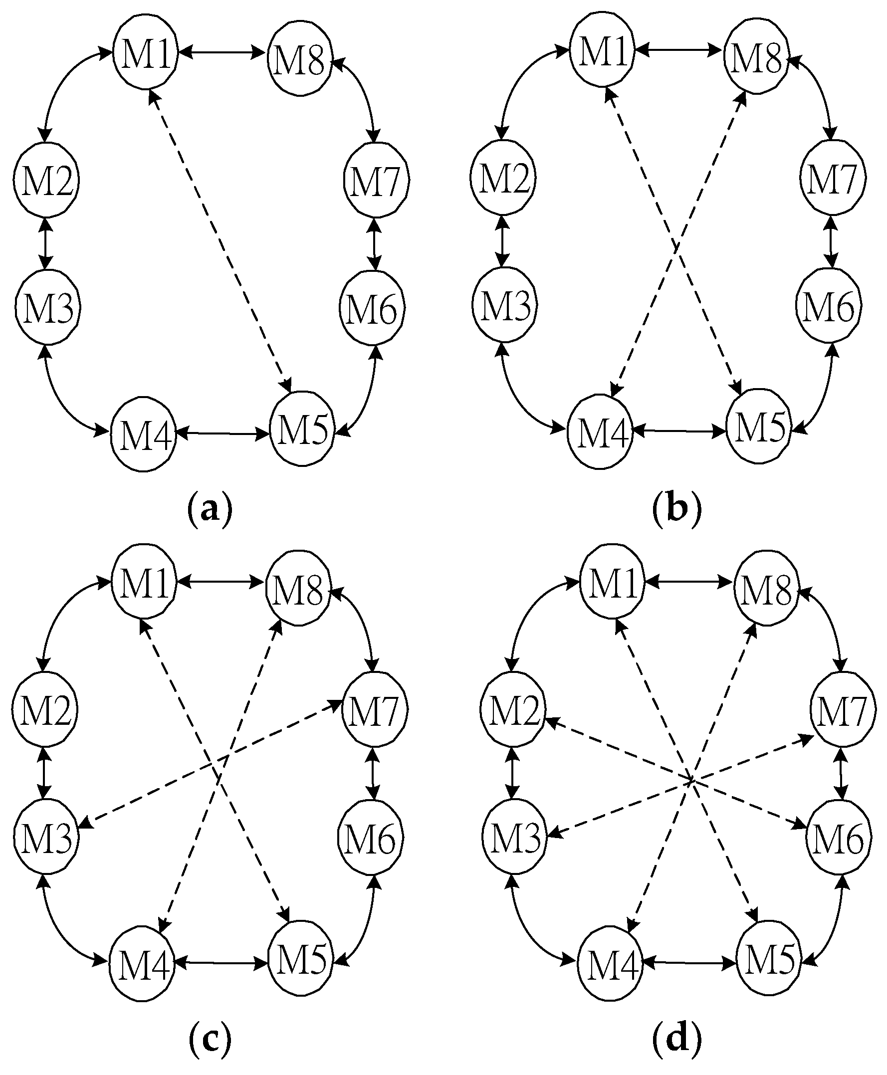
2.2. Mesh-Ring Formation Algorithm

To reduce the path length and mitigate the packet delay in the ring subnet, a Mesh-Ring scatternet formation algorithm with a shortest path routing algorithm is proposed in this study. The algorithm designs two phases to form the Mesh-Ring scatternet. In the first phase, a coordinator advertises and discovers its neighboring slave nodes, computes the Mesh-Ring topology and distributes node connection information to the masters in the ring subnet. In the second phase, each master in the ring subnet starts to build its corresponding piconet, connects with its neighboring piconets via slave bridges and interconnects with another corresponding piconet via one mesh link. Finally, a Mesh-Ring topology is generated.
In the first phase, a root designated as a coordinator discovers and queries its one-hop neighboring slaves to form the multi-hop scatternet. Whenever the root discovers another device in its proximity, it establishes a temporary piconet. Then, the root will be the master and the device that was in inquiry scan state will be the slave. After a certain period of time, the root can collect all its one-hop neighboring information.
After collecting all the neighboring information, the connection information is computed by the coordinator to form the desired multi-hop scatternet. To form a ring-based subnet, at least two bridge links are considered. In the ring subnet, one mesh link is introduced to reduce the packet transmission delay. In a piconet, the total number is eight and one master is used to schedule the packet transmission in a piconet. In order to mitigate the packet length in the ring subnet and maximize the piconet utilization, the minimum number of piconets is achieved under the formation constraint, and the formation criterion is defined as Equation (1).
p = n 7
where p is the minimum number of formation piconets, n is the total number of discovered nodes, including the coordinator and all discovered slaves. In general, the piconet number should be equal to n/8 in Equation (1), where 8 is the limit of the number of connected devices. However, each bridge node needs to connect with 2 piconets in the ring subnet, and this bridge can be counted twice in each piconet. Therefore, the remaining number of devices in a piconet is 6; thus, Equation (1) is divided by 7.
In Equation (1), the maximum number in a piconet is limited to eight. The bridge link is used to connect with the other two masters in the ring subnet. To connect the masters in the ring subnet, the number of masters is one and the maximum number of available mesh links is ml, which is equal to 7 × p n . After the scatternet topology is acquired, the minimum number of piconets is computed by Equation (1). After that, the coordinator computes and distributes the mesh link, the piconet information and the inter-piconet connection information to all the other masters in the ring subnet.
After receiving the piconet and inter-piconet information, each master starts to form its own piconet, interconnects with the other two bridges, and connects with the other corresponding master to form the mesh-ring topology. As a result, the identification of each master in the ring can be specified by the coordinator for packet routing over the ring subnet.
With a 52-node example, a coordinator M1 discovers 51 other slave nodes. With n = 52, M1 then computes the minimum number of piconet p = 8, and the number of available mesh links is 4. The 4 mesh links can be distributed by a maximum path criterion with path length p l = p / 2 . The pl value is used by the maximum path criterion in the master to connect with the farthest master, thus reducing the path length of the ring subnet. Finally, the coordinator M1 distributes the corresponding piconet, ring connection, and mesh connection information to all the other masters including M2 to M8 in Figure 2.
In the second phase, each master receives connection information including piconet information, inter-piconet connection information, and the mesh link information. The piconet information contains all the slave nodes in each individual piconet. The inter-piconet connection information includes bridges information to connect with its upward and downward masters in the ring backbone subnet. The mesh link information is used to connect with another corresponding master in the ring subnet. With the maximum path criterion, the path length in the ring subnet can be reduced to effectively mitigate the routing delay of packet transmission. At the same time, each master starts paging its downward master and connects them together as a ring backbone network. Then each master connects with one corresponding master in the ring to form the mesh-shaped subnet individually. In addition, each master pages its slaves in its piconet. As a result, the mesh-ring scatternet is generated to achieve both advantages of mesh and ring topologies.
In Figure 2, each master in the ring subnet from M2 to M8 receives piconet, inter-piconet connection, and mesh link information from M1. Then M2 starts to connect with its downward master M3, M3 connects with M4, M4 connects with M5. In this way, the ring backbone subnet is generated until M8 connecting with M1. With the maximum path length pl = 4, M1 connects with M5, M2 connects with M6 until the M4 connects with M8 to form the mesh-ring backbone network. Finally each master from M2 to M8 connects with its corresponding slaves and the mesh-ring topology is generated as shown in Figure 1.

2.3. Routing Algorithm

In general, the packet routing of the Mesh-Ring network can be classified into two cases, namely the intra-piconet routing and the inter-piconet routing cases. In the intra-piconet routing case, a source node and a destination node are located at the same piconet under a master. First, the packet is forwarded to the master, and then the master forwards to the destination in the corresponding slots of its piconet. In the inter-piconet routing case, the packets will be forwarded to the master of the source node in the piconet. Then the source master R i checks and delivers the packets to the immediate downstream master along the interconnecting mesh or the ring subnet, as well as passing the packets to the master of the destination. Finally, the destination master R j forwards packets to reach the final destination.
To reduce the hop length of a larger ring subnet and efficiently deliver packets, a criterion is defined in Equation (2) to minimize the hop distance between master i as R i and master j as R j . As long as a master in the ring subnet receives a new packet either from the piconet or the ring subnet, the master checks the mesh link first and the hop distance from the source ID to the destination ID will be computed by Equation (2). If Equation (2) is satisfied, the packet will be forwarded in the counterclockwise direction in the ring subnet. Otherwise, the packet will be forwarded in the clockwise direction.
R j R i c / 2 ; j > i
To create a full RMR network, the computation complexity is O (n2) and the formation message complexity is O (n). During scatternet formation, the connection messages do not affect packet transmission. On the other hand, the computational complexity of the optimal mesh connectivity is equal to O (p × ml) during the maintenance phase, where p is the number of piconets and ml is the number of available mesh links. In addition, the message complexity of the mesh connection is equal to O (ml), since only ml links need to be established. As a result, the impact on the connection message over the sending packets is quite small, since the connection message is triggered only as the topology changes.

3. Configurable Algorithm

During the topology maintenance phase, the size of a network dynamically changes as nodes join or leave the Mesh-Ring network. When the network size increases or decreases dramatically, the mesh size can be adjusted to achieve the desired network performance. Therefore, this study aims to determine the optimum number of mesh links for achieving the desired routing performance for various sizes of networks. After scatternet formation, the coordinator node acquires the local topology to reconfigure the Mesh-Ring topology as long as the topology variation exceeds a threshold. In order to determine the optimum placement of mesh link I in the ring subnet by the designated root, a heuristic algorithm called the peak-search method is proposed to achieve the best capacity performance of the RMR topology.

3.1. Problem Statement

During the topology maintenance phase, each master locally in the ring subnet can be connected with up to five more mesh links due to node leaves. As shown in Figure 1, the master initially connects with the other master that has the maximum hop length, such as M1 to M5. If a slave node leaves the M1 piconet, then the master is able to connect with one additional master with a mesh link via the maximum path criterion. The second connected master is M6, the third one is M4, the fourth one is M7, and the final one is M3. On the other hand, if a slave node joins the M1 piconet, then the M3 link is first removed, then the M7 link, and so forth in reverse, until arriving at the second mesh link. At least one mesh link in a piconet is required to maintain the Mesh-Ring topology. As a result, mesh connectivity in the ring subnet can be classified into three possible cases, including the piconet case, where the mesh links are located within a piconet as shown in Figure 3. The other one is the scatternet case, where the mesh links are distributed among several piconets, as shown in Figure 4. A hybrid case combines the mesh connectivity of Figure 3 and Figure 4. In addition, the execution round for the first mesh link is p and the last mesh link is 0, thus, the average execution round is p/2 to determine the optimal connectivity of mesh links.
In each piconet, there exist up to 5 links that can be connected as mesh links. In the piconet case, the 5 links are concentrated within a piconet, and the mesh links can also potentially be distributed among various piconets for the other scatternet cases. In general, the mesh links can be distributed among different piconets, and a combined configuration of piconet and scatternet cases is possible. Among the configurations above, the main research challenge issue in this study is how to determine the best throughput performance for the Mesh-Ring topology.

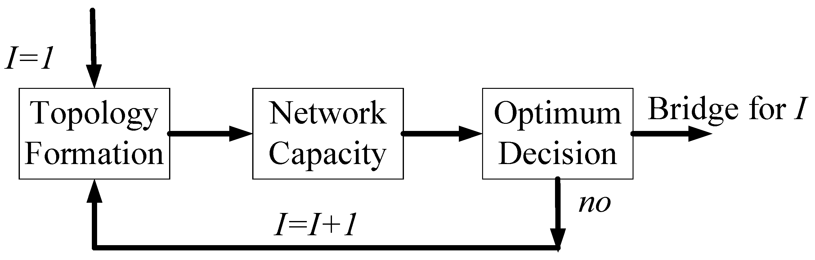
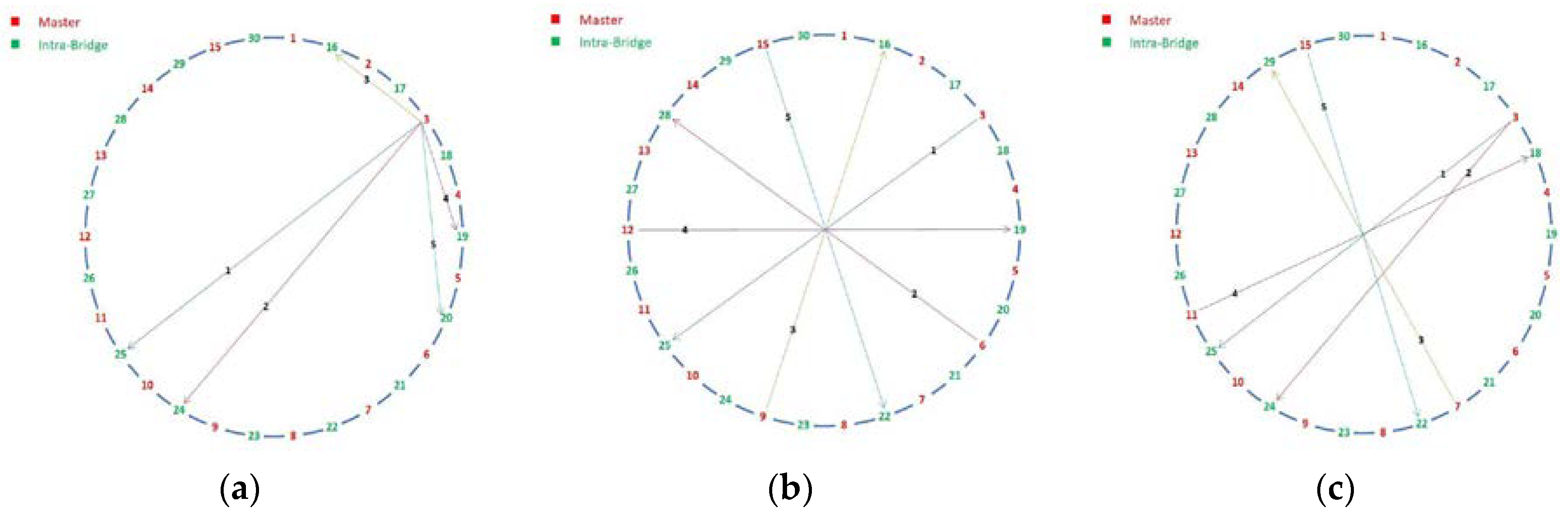
3.2. Reconfigurable Mesh-Ring Algorithm

The RMR algorithm introduces a peak-search method to locate the optimum placement of the available mesh links. The peak-search method contains three functional blocks, namely the topology formation block, the network capacity block, and the optimum decision block. To determine the optimal Mesh-Ring configuration for the three configuration cases of various sizes of networks, a peak-search method is presented. This scheme is a systematic approach, and is implemented by three functional blocks: the topology formation block generates the mesh-ring topology, the network capacity block computes the throughput performance, and the optimum decision block introduces a decision-making criterion to determine the optimum connected bridge node of each mesh link.
Figure 5 shows a block diagram of the peak-search method. Initially, parameter I is set as one and 1 I m l for the RMR formation, where ml is the maximum available mesh links. In the network capacity block, the average throughput performance is defined to reflect the scatternet capacity of total Mesh-Ring topology by summing up the piconet throughput on the ring. Finally, the total throughput is calculated and compared with its previous connected bridge in the optimum decision block. This algorithm is iterated until the optimum connected bridge of each mesh link I is determined.
To realize the peak-search method, a novel algorithm is implemented in the coordinator node of the RMR network for both topology formation and maintenance phases. At the beginning, the maximum number of mesh link ml is introduced as the counter of the mesh link. At the same time, the coordinator node collects sufficient information, including each average piconet throughput in the ring subnet, to calculate and compare the average mesh-ring throughput for the optimum decision block to make a decision.
From this point on, the designated root M1 in the ring-subnet periodically executes the peak-search method to determine the optimum connected bridge for each link I when the size of subnets grows or decreases. When the topology variation exceeds a threshold and the optimum I is not located in each time interval t, the designated master increases the connecting sequence of bridges by one to locate the mesh link I and continuously computes the average throughput in the ring subnet. This procedure is repeated until the optimum connected bridge for each I is determined.

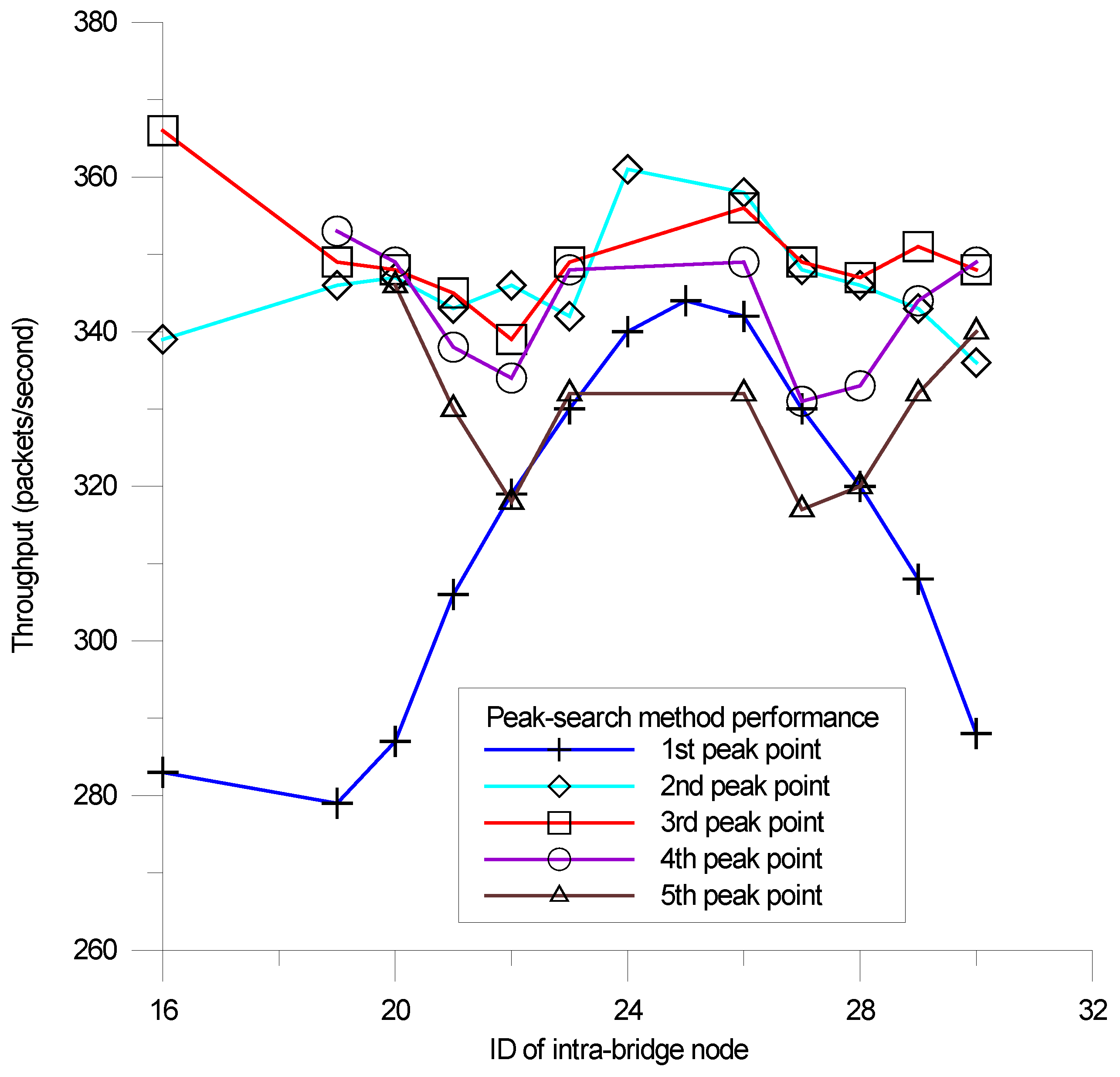
3.3. Peak-Search Method

In the scatternet formation block, the coordinator collects the complete topology and computes the formation topology including the ring subnet as well as the number of mesh links for the three configuration cases. In the network capacity block, the average Mesh-Ring throughput T is calculated by Equation (3), where Ri represents the total ring throughput of each individual piconet, and p is the number of piconets:
T = i = 1 p R i
In the optimum decision block, throughput performance Tj in Equation (3) is defined as the average Mesh-Ring throughput for the jth connected bridge in the network capacity block. Initially, j is set as one, and each Tj is calculated. Then j = j + 1, as the topology increases for the scatternet formation block, while Tj+1 is computed in the optimum decision block. The throughput performance of bridge j + 1 is computed until the maximum Tj is determined and the decision is made by Equation (4), where k is the total number of available bridges in the ring subnet.
M a x j = 1 k   T j
As a result, the bridge with the maximum throughput is regarded as the optimal connected bridge of mesh link I, and the algorithm is terminated until all connected bridges are determined for the available mesh links here.

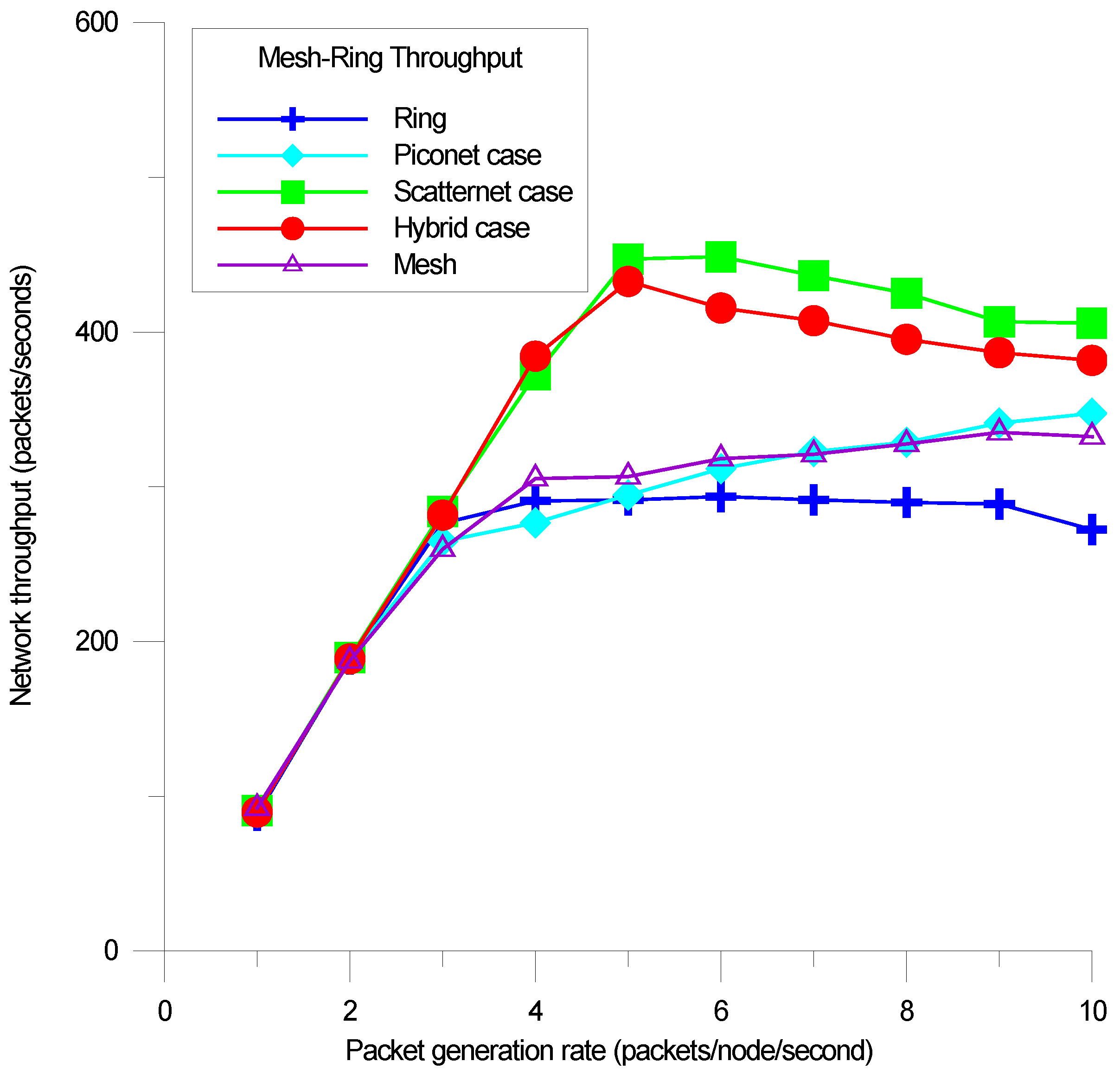
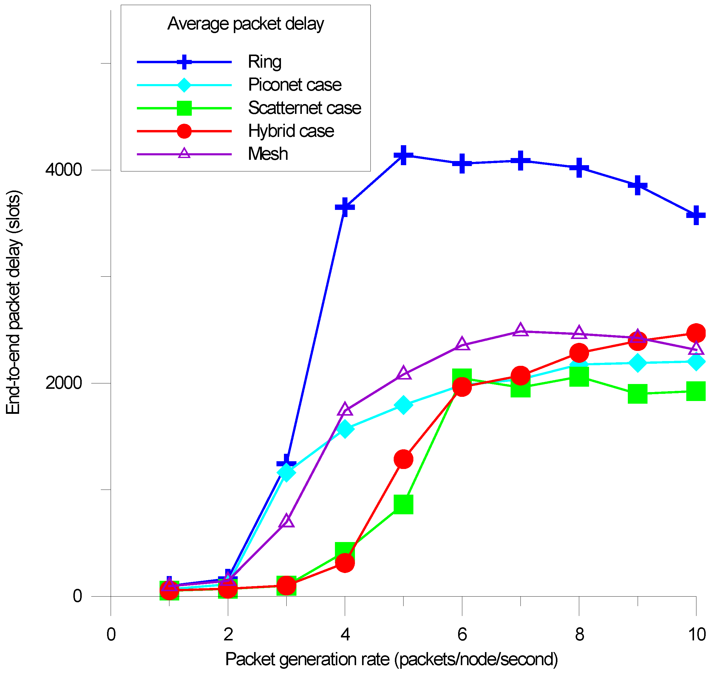
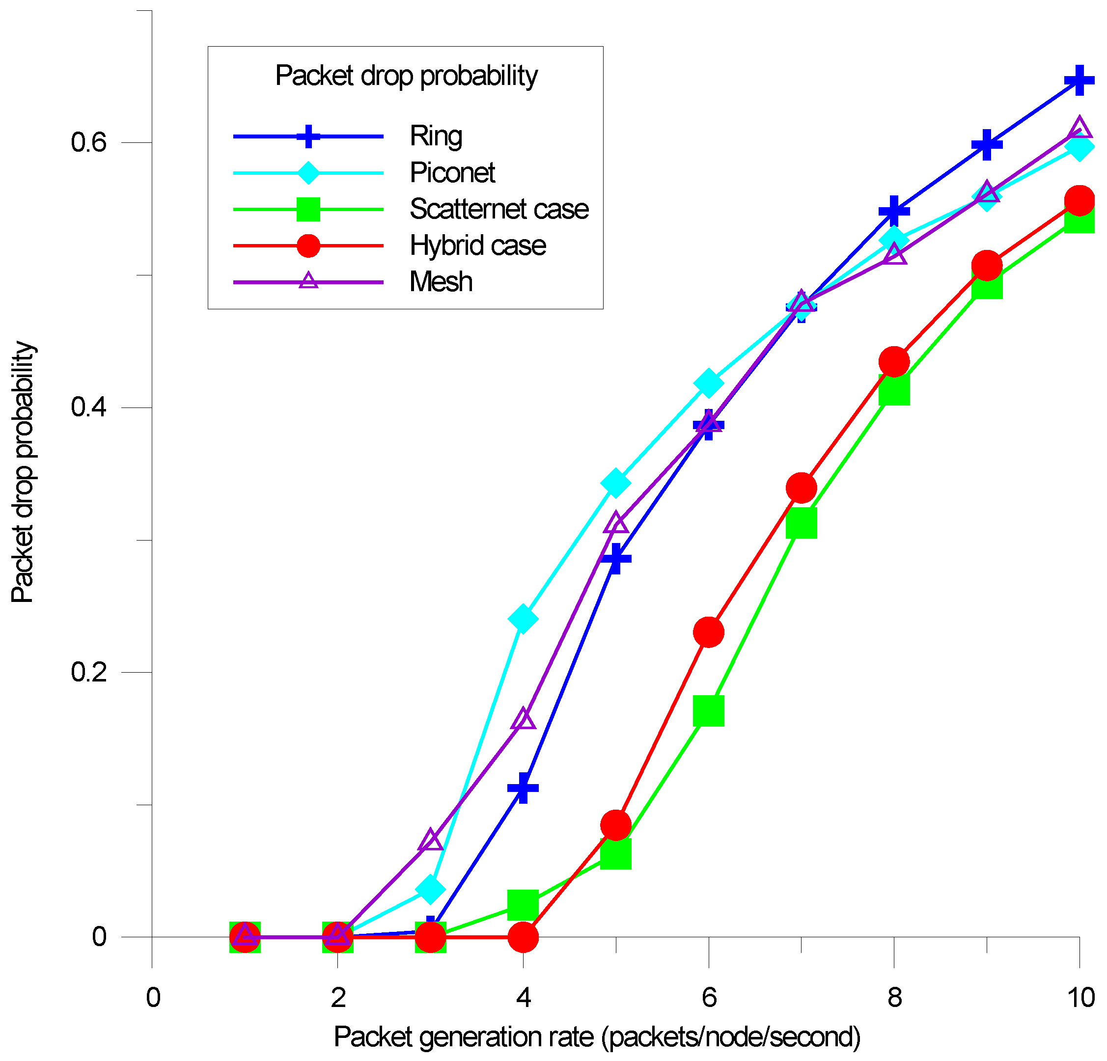
4. Performance Results

In this Section, a discrete event simulator is written by Matlab to investigate the network routing performance, and the configuration parameters for routing performance simulation are defined as follows. For the packet transmission of each node, each packet was generated in accordance with a Poisson arrival pattern. In addition, it was assumed that a single packet was sent in each routing session, and that each data packet had duration of five time slots. A first in first out (FIFO) queue was provided with a length of 80 packets for each node. When the buffer is in overflow, a FIFO buffer is used in each node, and a tail drop mechanism is designed to drop the packets. In each routing session, the source-destination pair was randomly selected, the time division duplexing (TDD) scheme was adopted for both piconet and scatternet scheduling, and packets were forwarded using the RMR with the designed routing protocol. The overall simulated nodes are 100, which are uniformly distributed in a specific area. From Equations (1) and (2), the resulting number of piconets is p = 15 and the number of mesh links is ml = 5.
Three simulation configurations are simulated, as in Figure 6. In the ring configuration, 15 masters with red color are interconnected by an intra-bridge with green color, which is a slave node to relay packets between interconnected piconets. Figure 6a is the piconet case, which is assumed to have 5 available mesh links in master 3. Figure 6b is the scatternet case with a uniformly distribution for mesh links among masters 3, 6, 9, 12, and 15. Figure 6c is the hybrid configuration of piconet and scatternet cases. In the hybrid case, it is assumed that there are two mesh links at master 3 and three mesh links distributed at 7, 11, and 15.
In Figure 6a of master 3, there exist various connection opportunities for the 5 mesh links via a bridge node from ID 16 to 30. Each bridge node is sequentially connected and simulated by master 3 to determine the highest throughput point. With a peak-search method, the 5 determined bridge nodes with highest throughput performance for the piconet case are shown as Figure 7. The first peak point is generated at bridge 25, which is shown by the blue line. The other determined peak points are 24, 16, 19, and 20. The simulation results demonstrate that the peak-search method works well to determine the optimal placement for each mesh link connection with the best throughput performance.
With the determined mesh links, three configurations are simulated, and their performances are shown in Figure 8. For the piconet case, three mesh links achieve the maximum throughput performance. For the scatternet and hybrid cases, the throughput performance increases as the mesh link increases. In addition, more mesh links achieve better throughput performances. As a result, the scatternet case achieves better throughput performance than the other two cases as the packet generation rate increases. The packet generation rate is defined as the number of packets generated in each node at a given time slot.
In [15], the cluster-based mesh topology demonstrates better routing performance than the conventional full mesh topology with the on-demand routing protocol. Our proposed Mesh-Ring topology is a type of cluster-based mesh architecture, and the ring routing protocol can operate for a larger network. After the RMR determines the optimal Mesh-Ring configuration, Figure 9 demonstrates the packet successful probability (PSP) for RMR with three cases, Ring and Mesh topologies. The RMR achieves almost 100% packet delivery ratio when the packet generation rate in each node is smaller than 4. The PSP in each node is defined as the total successful reception packets over the total network generated packets. The piconet case achieves better PSP than the Ring network when the packet generation rate is greater than 5. The scatternt case achieves the highest PSP than the other two cases. As a result, the RMR achieves superior performance on the PSP than the conventional Ring and the cluster-based Mesh topologies.
To reflect the scatternet capacity of RMR, a packet throughput is used to examine the overall network capacity. The average packet throughput in each device is defined as the ratio of the total number of successfully routed packets over the total simulation time in seconds. The simulation results of the packet throughput for the three configuration cases of RMR, the conventional Ring and Mesh schemes are as shown in Figure 10. The piconet case achieves approximate throughput performance, compared to the conventional cluster-based Mesh scheme. In RMR, the scatternet case achieves the highest throughput performance since the even distributed mesh links among masters effectively improves the connected configuration than the other two cases. On the other hand, the packet throughput of conventional Ring is promptly saturated, as the packet generation rate increases above 4 since the traditional ring topology increases the hop length and thus reduces the throughput performance in the ring subnet. According to the simulation results, the proposed RMR with scatternet case improves by almost 70% throughput performance, as compared to the conventional ring scheme.
In order to estimate the multi-hop routing performance, an average packet delay metric was used to measure the end-to-end delay of a scatternet. The packet delay of each routing packet is defined as the average packet transmission time from the first transmitted bit at the source node to the last received bit at the destination node. Figure 11 shows the average packet delay performances of the three cases of RMR, the conventional Ring and the cluster-based Mesh schemes. The packet delay increases as the packet generation rate increases since more packets have to be processed at network. The RMR scatternet case generates the smallest average delay, as it generates the even mesh connectivity than all the simulated cases. Another observation from the results is that the packet delay of the conventional Ring quickly increases versus the other three cases, as the packet generation rate increases above 4, because the traditional ring topology greatly increases the routing path length.
A packet drop probability (PDP) metric is used to evaluate the impact of traffic congestion in a scatternet. When the FIFO buffer overflows in each node, the damaged routing packets, including both the currently received and newly generated routing packets, were dropped. The PDP is defined as the ratio of the total number of dropped packets over the total generated packets for all nodes. Figure 12 shows the PDP of the three cases of RMR, the conventional Ring and the cluster-based mesh schemes. Here, the RMR scatternet case achieves the lowest PDP than all other cases, since the scatternet case achieves better mesh connectivity than the other ones. From the simulation results, it is clear that all masters begin to drop packets when the FIFO buffers overflow. Moreover, the packet generation rates are greater than 3 for the piconet case and the cluster-based mesh, 4 for the conventional ring and the scatternet case, and 5 for the hybrid case. From Figure 10, the throughput performance saturates even the packet generation rate, which increases when the packets start to be dropped in Figure 12. As a result, the tail drop mechanism can effectively manage the FIFO buffer and maintain throughput performance for network congestion conditions.

5. Conclusions

In this study, a RMR topology is proposed for Bluetooth multi-hop networks. The RMR constructs a ring topology as a backbone subnet, which is then extended by a mesh-shaped topology. To maximize network capacity, three configurations (including piconet, scatternet, and hybrid) are examined and demonstrated to determine the optimal placement of mesh links. In addition, the number of mesh link is adjustable to achieve the optimal network configuration. In order to determine the optimum bridge of each mesh link, a heuristic peak-search method is presented to achieve the desired throughput performance of the RMR network. The peak-search method is implemented by three functional blocks: the scatternet formation, the network capacity and the optimum decision blocks. Simulation results demonstrate that the optimal Mesh-Ring configuration can be determined by the peak-search scheme and the scatternet case achieves better overall network performances than the other two cases. Moreover, that RMR demonstrates better network routing performance than the conventional Ring and the cluster-based Mesh schemes for Bluetooth sensor networks.

Author Contributions

C.-M.Y. designed the RMR formation algorithm, routing protocol, formulated the mesh connection models, performed the simulation, and wrote the paper; B.-Y.W. and Y.-H.K. investigated the topology, validated the algorithms, analyzed the results and cooperated in designing the simulation.

Acknowledgments

This work was supported by the Ministry of Science and Technology of Taiwan, under Grants MOST 106-2221-E-216-002 and MOST 106-2221-E-009-050.

Conflicts of Interest

The authors declare no conflict of interest.

References

  1. Todorović, B.M.; Samardžija, D. Road lighting energy-saving system based on wireless sensor network. Energy Effic. 2017, 10, 239–247. [Google Scholar] [CrossRef]
  2. Hu, J. Application of ZigBee wireless sensor network in gas monitoring system. Acta Tech. CSAV 2017, 62, 255–264. [Google Scholar]
  3. Leccese, F.; Cagnetti, M.; Trinca, D. A smart city application: A fully controlled street lighting isle based on Raspberry-Pi card, a ZigBee sensor network and WiMAX. Sensors 2014, 14, 24408–24424. [Google Scholar] [CrossRef] [PubMed]
  4. Leccese, F. Remote-control system of high efficiency and intelligent street lighting using a zig bee network of devices and sensors. IEEE Trans. Power Deliv. 2013, 28, 21–28. [Google Scholar] [CrossRef]
  5. With an Installed Base of 10 Billion Devices Expected in 2018, Bluetooth Will Be an Essential Tool for Building the INTERNET of Everything. Available online: https://www.abiresearch.com/press/with-an-installed-base-of-10-billion-devices-expec/ (accessed on 4 May 2018).
  6. Fiandrino, C.; Capponi, A.; Cacciatore, G.; Kliazovich, D.; Sorger, U.; Bouvry, P.; Kantarci, B.; Granelli, F.; Giordano, S. CrowdSenSim: A simulation platform for mobile crowd sensing in realistic urban environments. IEEE Access 2017, 5, 3490–3503. [Google Scholar] [CrossRef]
  7. Satrya, G.B.; Reda, H.T.; Kim, J.W.; Daely, P.T.; Shin, S.Y.; Chae, S. IoT andw public weather data based monitoring & control software development for variable color temperature LED street lights. Int. J. Adv. Sci. Eng. Inf. Technol. 2017, 7, 366–372. [Google Scholar]
  8. Masek, P.; Masek, J.; Frantik, P.; Fujdiak, R.; Ometov, A.; Hosek, J.; Andreev, S.; Mlynek, P.; Misurec, J. A harmonized perspective on transportation management in smart cities: The novel IoT-driven environment for road traffic modeling. Sensors 2016, 16, 1872. [Google Scholar] [CrossRef] [PubMed]
  9. Calvo, I.; Gil-García, J.M.; Recio, I.; López, A.; Quesada, J. Building IoT applications with raspberry Pi and low power IQRF communication modules. Electronics 2016, 5, 54. [Google Scholar] [CrossRef]
  10. Pau, G.; Collotta, M.; Maniscalco, V. Bluetooth 5 energy management through a fuzzy-pso solution for mobile devices of internet of things. Energies 2017, 10, 992. [Google Scholar]
  11. Baker, C.; Almodovar-Faria, J.; Juste, P.S.; McNair, J. Low Energy socially cognizant routing for delay tolerant mobile networks. In Proceedings of the IEEE Military Communications Conference MILCOM 2013, San Diego, CA, USA, 18–20 November 2013; pp. 299–304. [Google Scholar]
  12. Etxaniz, J.; Aranguren, G. Modeling of the Data Transportation Network of a Multi-hop Data-content-sharing Home Network. IEEE Trans. Consum. Electron. 2015, 61, 31–38. [Google Scholar] [CrossRef]
  13. Hung, C.H.; Bai, Y.W.; Tsai, R.Y. Design of blood pressure measurement with a health management system for the aged. IEEE Trans. Consum. Electron. 2012, 58, 619–625. [Google Scholar] [CrossRef]
  14. Goh, H.L.; Tan, K.K.; Huang, S.; de Silva, C.W. Development of Bluewave: A Wireless Protocol for Industrial Automation. IEEE Trans. Ind. Inform. 2006, 2, 221–230. [Google Scholar] [CrossRef]
  15. Zhang, X.; Riley, G.R. Energy-aware on-demand scatternet formation and routing for Bluetooth-based wireless sensor networks. IEEE Commun. Mag. 2005, 43, 126–133. [Google Scholar] [CrossRef]
  16. Kamkuemah, M.N.; Le, H. A Study of Different Routing Protocols for Mobile Phone Ad Hoc Networks Connected Via Bluetooth. In Proceedings of the International Conference on Computer Modeling and Simulation (UKSim), Cambridge, UK, 10–12 April 2013; pp. 681–686. [Google Scholar]
  17. Jung, C.; Kim, K.; Seo, J. Topology Configuration and Multihop Routing Protocol for Bluetooth Low Energy Networks. IEEE Access 2017, 5, 9587–9598. [Google Scholar] [CrossRef]
  18. Sharafeddine, S.; Al-Kassem, I.; Dawy, Z. A Scatternet Formation Algorithm for Bluetooth Networks with a Non-uniform Distribution of Devices. J. Netw. Comput. Appl. 2012, 35, 644–656. [Google Scholar] [CrossRef]
  19. Chen, H.; Sivakumar, T.V.L.N.; Huang, L.; Kashima, T. Controlling network topology in forming bluetooth scatternet. IEICE Trans. 2005, 88, 943–949. [Google Scholar] [CrossRef]
  20. Yu, C.; Yu, Y. Reconfigurable Algorithm for Bluetooth Sensor Networks. IEEE Sens. J. 2014, 14, 3506–3507. [Google Scholar] [CrossRef]
  21. Zaruba, G.; Basagni, S.; Chlamtac, I. Bluetrees-scatternet formation to enable Bluetooth-based ad hoc networks. In Proceedings of the 2001 IEEE International Conference on Communications (ICC 2001), Helsinki, Finland, 11–14 June 2001; Volume 1, pp. 273–277. [Google Scholar]
  22. Cuomo, F.; Melodia, T.; Akyildiz, I. Distributed Self-Healing and Variable Topology Optimization Algorithms for QoS Provisioning in Scatternets. IEEE J. Sel. Areas Commun. 2004, 22, 1220–1236. [Google Scholar] [CrossRef]
  23. Salonidis, T.; Bhagwat, P.; Tassiulas, L.; LaMaire, R. Distributed topology construction of Bluetooth personal area networks. IEEE J. Sel. Areas Commun. 2005, 23, 633–643. [Google Scholar] [CrossRef]
  24. Persson, K.; Manivannan, D.; Singhal, M. Bluetooth scatternet formation: Criteria, models, and classification. In Proceedings of the First IEEE Consumer Communications and Networking Conference, Las Vegas, NV, USA, 5–8 January 2004. [Google Scholar]
  25. Liu, C.-H.; Dai, S.-W. The study for the extension of Bluetooth Ring network. In Proceedings of the International Conference on Multimedia and Information Technology, Kaifeng, China, 24–25 April 2010; pp. 127–130. [Google Scholar]
  26. Lin, T.; Tseng, Y.; Chang, K.; Tu, C. Formation, Routing, and Maintenance Protocols for the BlueRing Scattemet of Bluetooths. In Proceedings of the International Conference on System Sciences, Big Island, HI, USA, 6–9 January 2003; pp. 313–322. [Google Scholar]
  27. Guo, Z.; Harris, I.; Tsaur, L.F.; Chen, X. An on-demand scatternet formation and multi-hop routing protocol for BLE-based wireless sensor networks. In Proceedings of the 2015 IEEE Wireless Communications and Networking Conference (WCNC), New Orleans, LA, USA, 9–12 March 2015; pp. 1590–1595. [Google Scholar]
Figure 1. An illustrated Mesh-Ring topology example.
Energies 11 01163 g001
Figure 2. The formation topology of a Mesh-Ring backbone network.
Energies 11 01163 g002
Figure 3. The possible mesh link connection examples for each master in a piconet: (a) The first mesh link connection; (b) The second mesh link connection; (c) The third mesh link connection; (d) The fourth mesh link connection; (e) The fifth mesh link connection.
Energies 11 01163 g003
Figure 4. The possible mesh link connection example for each master in a scatternet: (a) The first mesh link connection; (b) The second mesh link connection; (c) The third mesh link connection; (d) The fourth mesh link connection.
Energies 11 01163 g004
Figure 5. Block diagram of the peak-search method.
Energies 11 01163 g005
Figure 6. The piconet case of Mesh-Ring topology (a); the scatternet case of Mesh-Ring topology (b); the hybrid case of Mesh-Ring topology (c).
Energies 11 01163 g006
Figure 7. The determined bridge node with highest throughput of peak search method for piconet case.
Energies 11 01163 g007
Figure 8. The determined mesh link with highest throughput of peak search method for three configuration cases.
Energies 11 01163 g008
Figure 9. The packet successful probability (PSP) performance of the Reconfigurable Mesh-Ring (RMR) algorithm.
Energies 11 01163 g009
Figure 10. The network throughput performance of the RMR algorithm.
Energies 11 01163 g010
Figure 11. The average packet delay performance of the RMR algorithm.
Energies 11 01163 g011
Figure 12. The packet drop probability (PDP) performance of the RMR algorithm.
Energies 11 01163 g012

