An ADRC-Based Control Strategy for FRT Improvement of Wind Power Generation with a Doubly-Fed Induction Generator

1
Key Laboratory of Knowledge Automation for Industrial Processes of Ministry of Education, School of Automation and Electrical Engineering, University of Science and Technology Beijing, Beijing 100083, China
2
Department of Automation Engineering, Technical University of Ilmenau, 98684 Ilmenau, Germany
*
Author to whom correspondence should be addressed.
Energies 2018, 11(5), 1150; https://doi.org/10.3390/en11051150
Submission received: 5 April 2018
/
Revised: 27 April 2018
/
Accepted: 1 May 2018
/
Published: 4 May 2018
(This article belongs to the Section F: Electrical Engineering)
Abstract
:This paper proposes a second-order active disturbance rejection control (ADRC)-based control strategy with an integrated design of the flux damping method, for the fault ride-through (FRT) improvement in wind power generation systems with a doubly-fed induction generator (DFIG). First, a first principles model of the rotor and grid side converter of DFIG is developed, which is then used to theoretically analyze the system characteristics and show the damage caused to the DFIG system by a grid voltage fault. Then, the flux damping method is used to suppress the rotor current during a fault ride-through. In order to enhance the robustness and effectiveness of the flux damping method under complex working conditions, an ADRC approach is proposed for disturbance attenuation of the DFIG systems. Finally, a comparison of the proposed method with three other control approaches on a 1.5-MV DFIG system benchmark is performed. It is shown that the proposed method can adaptively and effectively improve the system performance during an FRT.
1. Introduction
As the world continues to consume ever greater amounts of energy, the need for alternative sources of energy is increasing. Wind generation is one such source that has the potential to provide some of the required power [1]. Of the different types of wind energy conversion systems (WECS), the doubly-fed induction generator (DFIG), due to its wide speed range, independent adjustment of the active and reactive power, and smaller rating of the excitation converter, occupies the largest proportion of the market [2]. In the DFIG system, the generator stator is directly connected to the grid, while the rotor is integrated into the grid via a back-to-back converter. Due to the way the system connects to the grid, the voltage fault ride through (FRT) capability is considered to be one of the largest challenges in the control and optimization system design of wind turbines [3].
When a fault occurs, the grid voltage dips instantly and the energy produced by the DFIG cannot be transmitted to the power grid, which will lead to an accumulation of the capacitor voltage and a sudden increase in the rotor current. This may even cause damage to the converter and the DFIG motor [3,4]. In order to improve the FRT capability of the DFIG system, the state of the art focuses on the following two approaches: (1) hardware protection [5] and (2) control and optimization approaches. The hardware protection approach uses the rotor-side crowbar circuits to short-circuit the generator rotor for dealing with the emergence of the grid faults [6]. Its effectiveness and ease of implementation for performance improvement have been shown for severe voltage dips. However, in the process of protection, the DFIG system could lose control and absorb a large amount of reactive power from the power grid and cause further grid voltage degradation. Moreover, the electromagnetic torque will seriously oscillate when the crowbar circuit moves, leading to fatigue and aging of the mechanical equipment in the DFIG transmission system [7]. Other approaches, such as the energy storage system (ESS) [8], additional series grid side converter (SGSC) [9], and DC-chopper circuit [10], have also been shown to be effective, but with a corresponding increase in hardware costs.
The control and optimization approach seeks to suppress the current fluctuations of the rotor-side converter (RSC) by some advanced control/optimization methods. Compared with the crowbar (hardware) method, these types of algorithms can realize the fault ride-through without any additional hardware, and the DFIG system’s performance can be maintained. Limited by the capacity of RSC, the controllable range is discussed in [11]. In [12] the stability of the flux linkage of DFIG system was analyzed, and the flux damping method was proposed to improve the system transient process. In [13], the input timing of the flux damping signal was considered, which further reduces the loss of the system running. However, these papers only considered low-voltage ride through (LVRT) situations. In [14], a control method based on accurate model compensation is proposed. By calculating the stator flux linkage in real time, the DC and negative component can be compensated. However, this method is strongly dependent on model accuracy. In [15,16], feedback linearization and a robust controller are used to design the control system, but the system design is usually complex. In [17,18] the ADRC controller is used to reduce dependency on system models, but only the first-order controller is used. The second-order ADRC has better adaptability and robustness to the system model.
Thus, due to the complexity of the DFIG system model and the unknown disturbances in system operation, such as modeling error, equipment aging, and parameter drift, the control effect of the RSC will be reduced. Previous work [13] mainly focused on changing the input parameters of the flux damping method to achieve better LVRT control effect. However, when dealing with the complex working conditions and model parameter drift, it cannot maintain good control. On this basis, in order to pursue a more stable and robust control effect, the ADRC controller is considered. In general, for first-order systems, the first-order ADRC can achieve fast tracking control with no overshoot [17]. However, due to the complexity of the DFIG system, it is difficult to simplify it to a first-order plant. For example, we usually simplify the magnetic field of the generator to a second-order damped oscillatory system. Thus, better control performance and higher robustness can be achieved by using a second-order ADRC.
Motivated by the aforementioned studies, for the purpose of the FRT improvement for DFIG system, an optimization method based on an ADRC controller with an integrated design of the flux damping method is proposed in this paper. Firstly, the model of the RSC and grid-side converter (GSC) of the DFIG is introduced. The system characteristics of the model are analyzed theoretically, and the damage to the DFIG system is explained. Then the flux damping method is introduced and the integration process with the flux damping and ADRC is explained. Furthermore, the ADRC approach is proposed to reduce the internal and external disturbance of DFIG system under complex working conditions. Finally, a 1.5-MV DFIG system was tested and compared with three other control methods, to show its adaptability and effectiveness on FRT improvement performance.
2. DFIG Model
In this section, the RSC and GSC model for the DFIG is introduced. As well, the damage caused by a grid voltage fault is shown and discussed. We briefly explain the notation used in this paper: v is the voltage, i is the current, R is the resistance, ψ is the flux linkage, L is the inductance, Lls and Llr is the leakage inductance of the stator and rotor, Lm is the mutual inductance. ω is the angular frequency, and ω1 is the slip frequency defined as ω1 = ωs − ωr. The subscript s represents the stator, and the subscript r represents the rotor. The subscript g represents the grid, subscript dc represents the DC-bus, and subscript gc represents the GSC control side. In the synchronous dq-reference frame, the subscript d represents the direct directions component and q the quadrature directions component. The positive direction of each vector is shown in Figure 1.
2.1. Control Model of Rotor Side Converter (RSC)
The basic model of the DFIG, shown in Figure 1, assumes that the DFIG has three-phase symmetric windings, that the air gap flux is uniform, and that the magnetic path is symmetrical. The hysteresis, eddy current loss, and iron loss are ignored. The basic equations of the voltage and flux linkage are:
The rotor variables are all referred to the stator for simplicity.
Transforming Equation (1) into the synchronous dq-reference frame gives:
The active, P, and reactive, Q, power in the stator of the DFIG are:
Using the stator flux orientation, which implies that ψsq = 0, the flux equation becomes:
Assuming that the stator flux linkage cannot be changed and that the resistance is negligible, the stator voltage equation can be simplified to:
where Vsp is stator phase voltage and ψsd = Vsp/ω1. Substituting Equations (4) and (5) into Equation (3), the power equation can be expressed as:
From Equation (6), it can be seen that the active power and reactive power of stator are determined only by the variables irq and ird. This means that the power can be decoupled.
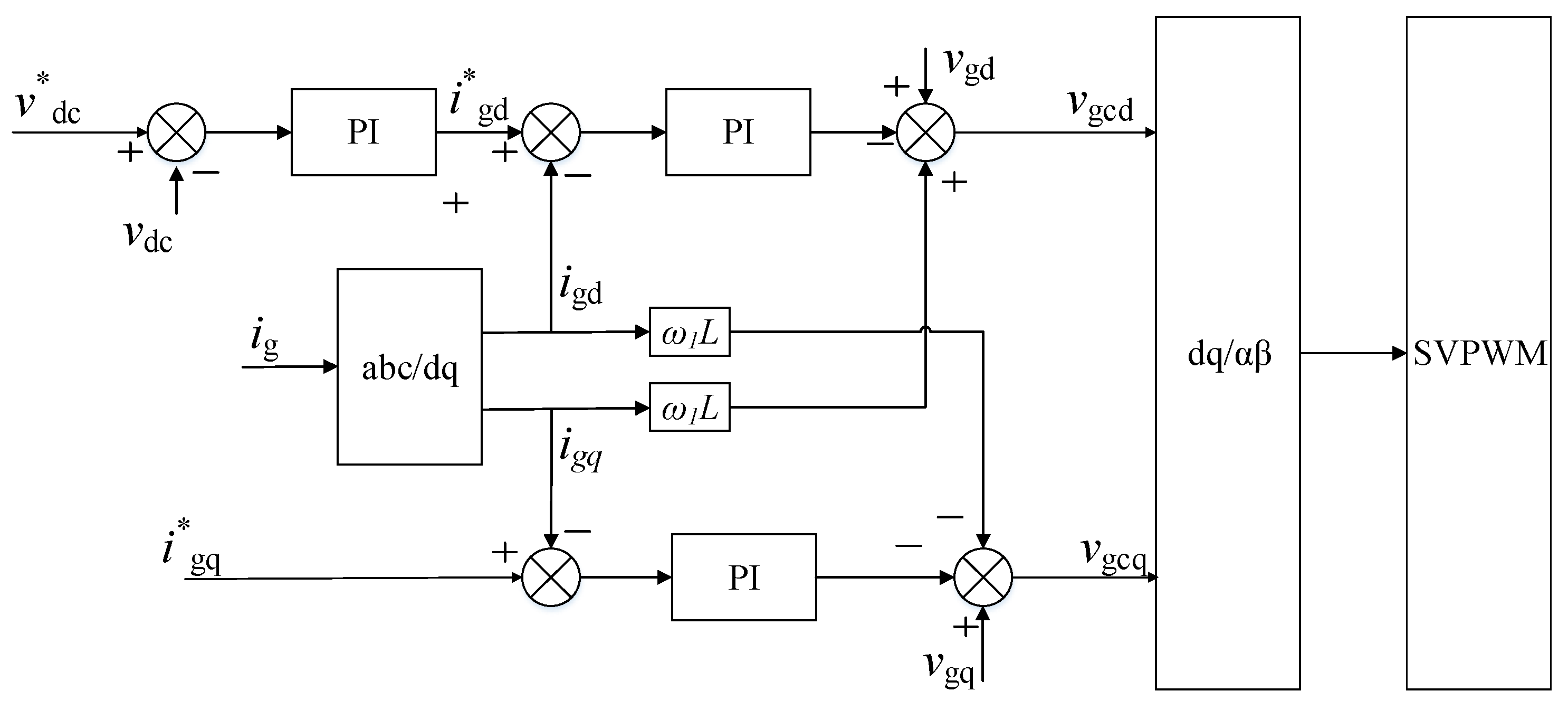
2.2. Control Model of Grid Side Converter (GSC)
The purpose of the GSC controller is to maintain the DC capacitance voltage and control the power factor of DFIG.
The basic voltage equation in the synchronous dq-reference frame is [19]:
Let vgq = 0, then the power from the grid to the GSC can be written as:
From Equation (9), it can be seen that the active power and reactive power are determined only by the variables igd and igq. Thus, the grid-side power can also be decoupled.
In addition, based on the instantaneous power theory, the reactive power can only be transmitted to the grid, which means it cannot be sent to the DC-link. Thus, we can control the DC-link voltage using the active current igd.
Similar to the control of the RSC, the current control of the GSC is based on the voltage control. Thus, we should determine the relationship between voltage and current.
According to Equation (6):
Using Equations (9) and (10), the control model of the GSC can be obtained, as shown in Figure 3.
2.3. Behavior Analysis of Grid Faults
Since the stator of the DFIG is directly connected to the power grid, when a grid voltage fault occurs, the stator voltage will instantaneously follow the fault. However, the stator flux linkage is an integral value, which cannot be changed instantaneously. Thus, if the power grid faults, a large number of DC flux linkages components will be generated. At this point, the stator flux is no longer a circular rotating magnetic field, but a complex magnetic field include rotating magnetic field and DC magnetic field. Then, the rotor which is still rotating and driven by the wind turbine, will cut the irregular stator magnetic field, which can lead to overvoltage and overcurrent of the rotor winding. The electromotive force (EMF) under symmetrical faults is [4]:
where er is the EMF induced by the stator flux linkage, s is the slip, Vs is the amplitude of the stator voltage, p is the change of the grid voltage, and τs is the time constant of the stator flux linkage. The first term is induced by the positive stator flux linkage, while the second term is induced by the DC component of the stator flux linkage. Under a full voltage dip with s = −0.2, the initial amplitude of the EMF is 1.2 VsLm/Ls, which is six times that under normal conditions.
If an asymmetric fault occurs in the power grid, the rotor overvoltage and overcurrent will be more complicated. Since the negative sequence component is contained in the stator flux, the negative sequence component can produce a greater deviation [3]. In the same way, the EMF under asymmetrical faults is:
where V1 and V2 are the amplitudes of the positive and negative sequence components of the stator voltage, respectively, and ψsdc is the amplitude of the initial DC component. It can be seen that when V1 = V2 and s = −0.2, the EMF can be 11 times larger than under normal conditions.
Finally, the overcurrent can damage the rotor converter, and the overvoltage will break the winding insulation. On the other hand, part of the excess energy can be sent to the grid through the GSC. However, the rest of the energy can only flow to the capacitor, which will force the capacitor voltage to rapidly rise. Obviously, this will damage the DFIG hardware. Based on the aforementioned analysis, it is necessary to improve the FRT ability of the DFIG.
3. Flux Damping Method
The purpose of FRT is to protect the power grid and power equipment when the fault occurs. It requires DFIG to keep running for a period of time during a power grid fault to help the grid recover. Immediate off-grid behavior can trigger a chain reaction between devices and aggravate the power grid fault [3]. The aim of the flux damping method is to suppress the rotor current during a fault ride-through and accelerate the dynamic process, help the DFIG quickly passing the FRT time. However, the system has are complex working conditions, including such issues as modeling error, equipment aging, parameter drift, and unknown disturbance. Under such situations, the control effect of the DFIG will be greatly reduced, and the FRT ability will also be reduced. In order to increase the robustness of the system and reduce dependency on system models, ADRC controller is used to replace the traditional Proportion Integration (PI) control. This effectively improves the antidisturbance ability of the DFIG control and greatly increases the robustness and effectiveness of the flux damping method. The flow chart of the integrated design of ADRC and flux damping method are showed in Figure 4.
3.1. Flux Linkage Analysis in the Grid Fault
When a power grid fault occurs, the stator flux cannot instantaneously follow the stator voltage, causing the rotor side current to quickly increase, which, in turn, causes the DC voltage to increase.
In traditional vector control, according to Equation (2), the flux vectors in the synchronous dq reference frame are [12]:
Taking the derivatives of both sides, setting the stator voltage to be constant, and using the differential operator s, the results are:
Then the stator flux linkage can be expressed as:
From Equation (2), we get . Substituting into Equation (15) gives:
The constant terms are ignored.
From Equation (4), we get . Substituting isd into Equation (16) gives:
Then the characteristic equation of the stator flux is , and the characteristic root is:
From Equation (18), it can be seen that the stability of the stator flux is only related to stator inductance and stator resistance. Since Rs is usually very small [12], the transient time is quite long.
Thus, when a grid fault occurs, the traditional vector control cannot suppress the transient DC component of the stator flux linkage, which will lead to overvoltage and overcurrent in the DFIG system.
At the same time, if we can reduce the rotor current, and weaken the transient flux linkage or “flux damp”, it will accelerate the transient time and help DFIG overcome the fault. The instantaneous power can be transformed into reactive power feeding into the power grid.
3.2. Flux Damping Method
In order to change the dynamic characteristics of the stator flux, we need to fix the current underdamped state of the system.
From the aforementioned analysis, it can be seen that adding a virtual resistor into the current loop can increase the damping coefficient of the system. However, the existence of a virtual resistance will increase the loss during normal operation [13].
Switching to the current loop control method, Equation (13) can be written as:
where i*rd is the compensating current.
Then, once the compensating current i*rd can be obtained, this will increase the dynamic response of the system and help the DFIG overcome the LVRT. Thus, this approach can be called a flux damping current.
Using the stator flux orientation, which means that ψsq = 0, we need to control the d-axis current decrease. Then the characteristic equation can be given by:
The new characteristic root is:
From Equation (21), it can be seen that by reducing the set value of the rotor current, the negative real part of the characteristic root increases, which means, the transient time of the stator flux chain is accelerated. Changing Kref can also change the compensation current i*rd. A larger compensation current can speed up the transient time of the system. However, it cannot be arbitrarily large, because the rotor current value is limited to the maximum capacity of the RSC converter [11].
According to the capacity of the converter, the current value is limited to the following equation:
where ird_ref and irq_ref are the set value of the rotor current in d and q axis, respectively, and ir_max is the maximum current of the converter.
The structure diagram of the flux damping current is shown in Figure 5.
4. Active Disturbance Rejection Control Controller Design
The active disturbance rejection control (ADRC) was developed by Han [20], which is a robust control technology and the structure is shown in Figure 6 [21].
As a matter of fact, ADRC inherits the advantages of traditional PID control and aims to improve the PID controller [22]. Without relying on an accurate process model, ADRC has strong anti-disturbance ability, high accuracy, quick response, and a simple structure [23]. Using modern control theory, the tracking differentiator (TD), the extended state observer (ESO) and the state error feedback control law (SEF) greatly improve the robustness of system.
TD was originally intended to extract differential signals by tracking a given signal as quickly as possible. Currently, TD is often used to arrange the transition process [20]. The ESO is used to estimate the system model and disturbances. From the perspective of the ESO, the model and the disturbances are equally important since they can both be compensated by the extended state. ESO transforms the uncertain system into an “integral series”, which is a structure of feedback linearization for nonlinear uncertain systems. This estimate does not depend on a precise mathematical models, since it is a dynamic estimate [24,25].
The control structure of RSC with ADRC is shown in Figure 7.
4.1. Tracking Differentiators (TD)
In order to avoid high-frequency disturbance, the discrete form of the TD can be expressed as [21]:
where h is the sampling period, v(k) is the input signal at time k, and r is the parameter that determines the tracking speed. The function fst(.) is the fastest controlled synthesis function, which is defined by:
where , , , .
4.2. The Extended State Observer (ESO)
The control system is represented as:
where f (x1, x2) is unknown, but bu is known.
Let the unknown part be , then Equation (26) can be expressed as:
Using the ESO, we can get the system speed without a speed measurement device and predict the unknown part.
For the second-order ADRC controller, the extended state observer is third order, and the design method is:
where βi > 0 (i = 1, 2, 3), α1 = 0.5, and α2 = 0.25. The saturated function fal(e, α1, δ), which is used to suppress signal shaking, which is defined as:
So that z1 can follow the system state x1, z2 can follow the system speed x2, and z3 can follow the unknown part x3:
z3 is called the state of being expanded.
It can be seen that ESO can predict the magnitude and direction of the disturbance signal and compensate the disturbance in time.
4.3. The Advantages of Second-Order ADRCs
The design concept of first-order ADRC is to approximate the controlled system to a first-order system, and remove the TD part to accelerate the response time [17]. Applied to first-order system, it has good control effect with fast response, no overshoot, and strong robustness. At the same time, the lower order reduces the control parameters that need to be adjusted [21].
The second-order ADRC has more extensive application scenarios than first-order ADRC. For example, the first-order inertia system with time delay, the second-order inertia system with time delay, the integral system with time delay and other single input single output (SISO) systems. Moreover, it can be used for decoupling control of multiple input multiple output (MIMO) systems and uncertain input system with time delay [24]. Under complex working conditions the DFIG system can hardly be regarded as a simple first-order system. For example, we usually simplify the magnetic field of the generator to the second-order damped system. Combined with parameter drift and model mismatch, it may also add time delay and inertial part to the system. Therefore, the second-order ADRC with higher robustness is a more reasonable choice.
Furthermore, the second-order ADRC has better disturbance prediction ability. Unlike the first-order ADRC, which can only predict the position signals, the second-order ADRC can calculate the speed signal in real-time. The control signal is adjusted by the position signal and the speed signal, so that the control process is more accurate and smoother.
Figure 9 shows the step response diagram of a second-order integral system using both a first-order and second-order ADRC controller. It can be seen that when the first-order ADRC is applied to a second-order system, the control performance degrades. The overshoot of the system will be increased and the adjustment time will be lengthened.
5. Case Study
This section proposes the model of the DFIG that will be used for a case study of the typical 1.5-MW DFIG based WECS to verify the proposed control method. In the following case study, a comparison is carried out between the proposed method and a typical method based on vector PI control.
The specific parameters of DFIG motor are shown in Table 1. The parameters of the DFIG have been converted to the stator side [13].
5.1. System Performance under Symmetrical Faults
5.1.1. Symmetrical Voltage Faults with 60% Dip Scenarios
Initially, the input wind speed is 10 m/s, while the output reactive power of the stator Qs is zero. The corresponding slip of the DFIG is −0.2. At t = 0.2 s, a symmetrical voltage dip fault appears on the stator terminal with recovery at t = 0.4 s. However, due to the lag of the reactive power compensation, the recovery voltage increases to 120%. At t = 0.6 s, the grid voltage finally returns to normal.
We simulate two situations, 60% voltage dip depth and 80% voltage dip depth. The advantages and disadvantages of vector PI control, “flux damping” control and second-order ADRC with “flux damping” control are analyzed and compared.
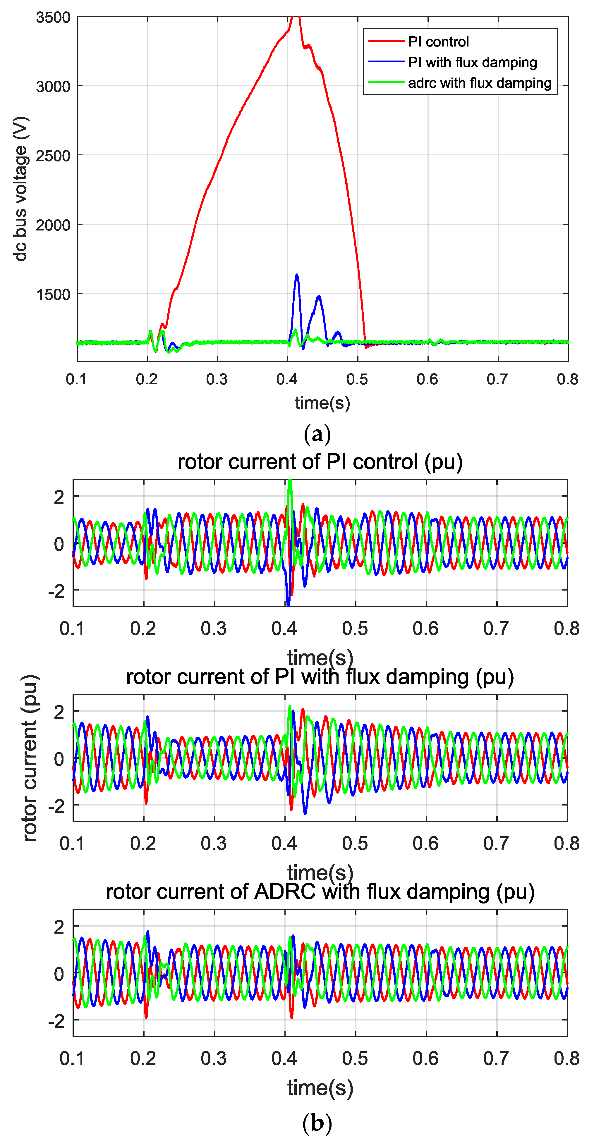
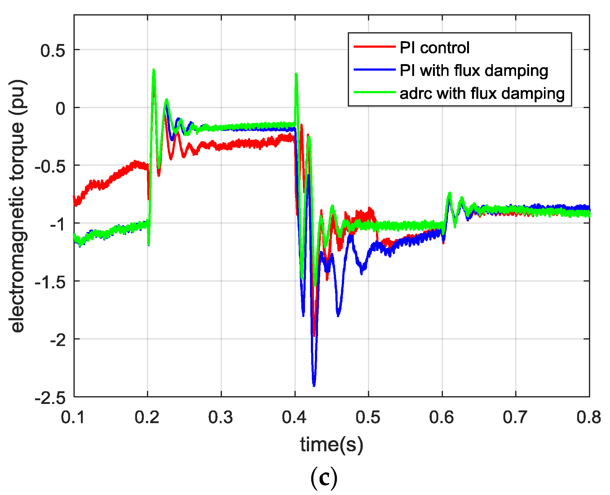
From Figure 10a, it can be seen that DFIG with vector PI control is unable to consume the excess energy generated by the stator flux change in a short period of time. The rotor current will reach 2.6 pu, the voltage of the DC bus will break through 1.2 pu, and the electromagnetic torque will fluctuate for a long time. The control system cannot effectively help DFIG through the fault.
Figure 10b shows the same situation but with a “flux damping current”. It can be seen that the rotor current in the fault period was obviously inhibited. The maximum DC bus voltage and electromagnetic torque fluctuations are also improved. In the case of a 60% voltage dip, the “flux damping” method can limit the rotor current to 2 pu and help the DFIG through the fault time.
Finally, Figure 10c shows the results, when using ADRC with “flux damping”, which combines the advantages of “flux damping” and ADRC. In this case, the rotor current is restricted effectively and the inaccuracy and unknown disturbance of the model are suppressed. Moreover, in the case of 60% voltage dip, the ADRC with “flux damping” method gives good performance for the rotor current, DC bus voltage, and transient performance of electromagnetic torque.
The specific control performance index are shown in Table 2. The maximum DC bus voltage (VDC_max), the maximum rotor current (Ir_max) and the regulation time of the electromagnetic torque (Tm_ts) are selected as the key parameters to compare the control performance [26]. It can be seen that the VDC_max for PI control reaches 1392 V during the voltage dip, which exceeds the DC bus voltage setting value (1150 V) by 21%, while the ADRC approach keeps the value below 7%. At the same time, the Ir_max for PI control is over 2.0 pu, which will trigger the protection of the hardware crowbar and make the DFIG lose control ability [6]. Compared with PI control, the “flux damping” method and ADRC approach can successfully control the rotor current below 2.0 pu.
5.1.2. Symmetrical Voltage Faults with 80% Dip Scenarios
Similar to the above results, the control performance in a severe voltage fault is shown more clearly.
Figure 11a shows the results for an 80% voltage dip controlled by a standard vector PI control. From Figure 11a, it can be seen that in the severe voltage fault, DFIG with vector PI control has already lost control. Excess energy causes the rotor current to increase and makes the DC bus voltage uncontrollable. This is strictly forbidden in the DFIG system. The high DC-side voltage will cause the DFIG to be released from the network prematurely and could potentially lead to a chain reaction in the remaining WECS [2]. Moreover, the rotor side current reaches 3.3 pu, while the electromagnetic torque, active power, and reactive power are all unstable. It can be seen that, in the case vector PI control could not help DFIG system passing the grid fault.
Figure 11b shows the results for an 80% voltage dip controlled using the “flux damping” control method. It can be seen that the control of the rotor current has been greatly improved. Meanwhile, the DC bus voltage is limited to 1.4 pu. However, the dynamic response of the system still takes a long time. As well, the crowbar circuit will be activated since the rotor current reaches 2.0 pu.
Finally, Figure 11c shows the results for an 80% voltage dip controlled by an ADRC with flux damping control system. It can be seen that the rotor current has good suppression effect, and the dynamic process of the system is greatly improved. The DC bus voltage is limited to 1.1 pu and the rotor current can be controlled to below 2 pu. Under a severe voltage dip, the ADRC controller can effectively speed up the transient process, reduce uncertainty caused by inaccurate models, and compensate for the disturbance in the energy impact process. It can be concluded that the ADRC could help the DFIG system overcome a severe symmetrical voltage fault.
The performance indices are shown in Table 3. It can be seen that the maximum DC bus voltage for PI control reaches 3580 V during the voltage dip, which exceeds the DC bus voltage setting value by 211%, which is strictly forbidden. On the other hand, the flux damping method and ADRC keep the value at 40% and 11%, respectively. At the same time, Ir_max for PI control and flux damping method is 3.3 pu and 2.3 pu, respectively, it will trigger the hardware crowbar. Compared with them, ADRC approach can successfully control the rotor current below 2.0 pu.
5.2. System Performance under Asymmetrical Faults
The performance of the proposed method under single-phase faults is also examined. At t = 0.2 s, an asymmetrical fault of the voltage dip appears on the stator phase A with recovery at t = 0.4 s.
In practice, asymmetrical faults are more frequent. In the process of an asymmetric fault, energy impact is not as much as symmetrical fault, but it will produce a negative sequence current and zero sequence current, which will cause the double frequency jitter and, thus, generate fatigue loss [4].
Figure 12 shows the performance of the DFIG system when an 80% asymmetric voltage dip occurs under both standard vector PI control and the proposed ADRC with flux damping methods. It can be seen from Figure 12 that, under PI control, the increase of DC voltage is not much, but due to the existence of negative sequence current, voltage jitter is obvious. At the same time, the electromagnetic torque also has a large value vibration. With ADRC with “flux damping” control, the amplitude of DC voltage is suppressed better and the jitter is also reduced. Furthermore, the vibration of the electromagnetic torque is obviously improved.
5.3. System Performance for Disturbance Attenuation
The parameters of the generator will change with the temperature when the system is running. For example, the rotor resistance increases with an increase in temperature, and the mutual inductance decreases with the saturation of the magnetic circuit. Equipment aging and insulation loss also gradually change the system parameters. If the control system is designed with constant control parameters, when external disturbance or parameter changes occur, the overall performance will be seriously affected. Therefore, external disturbance and parameter changes are added to test the robustness of the system.
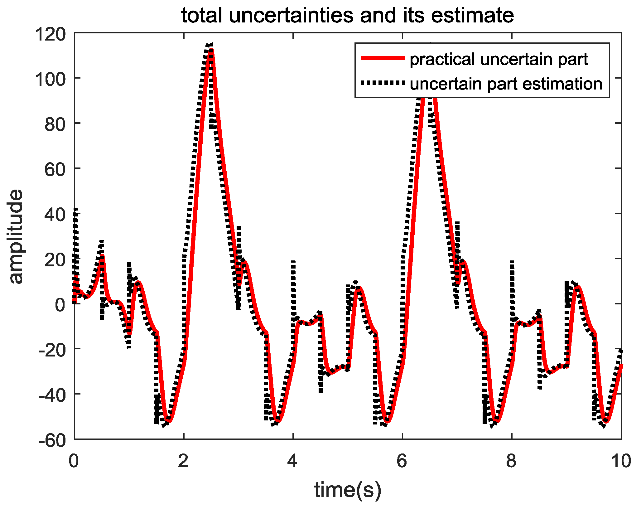
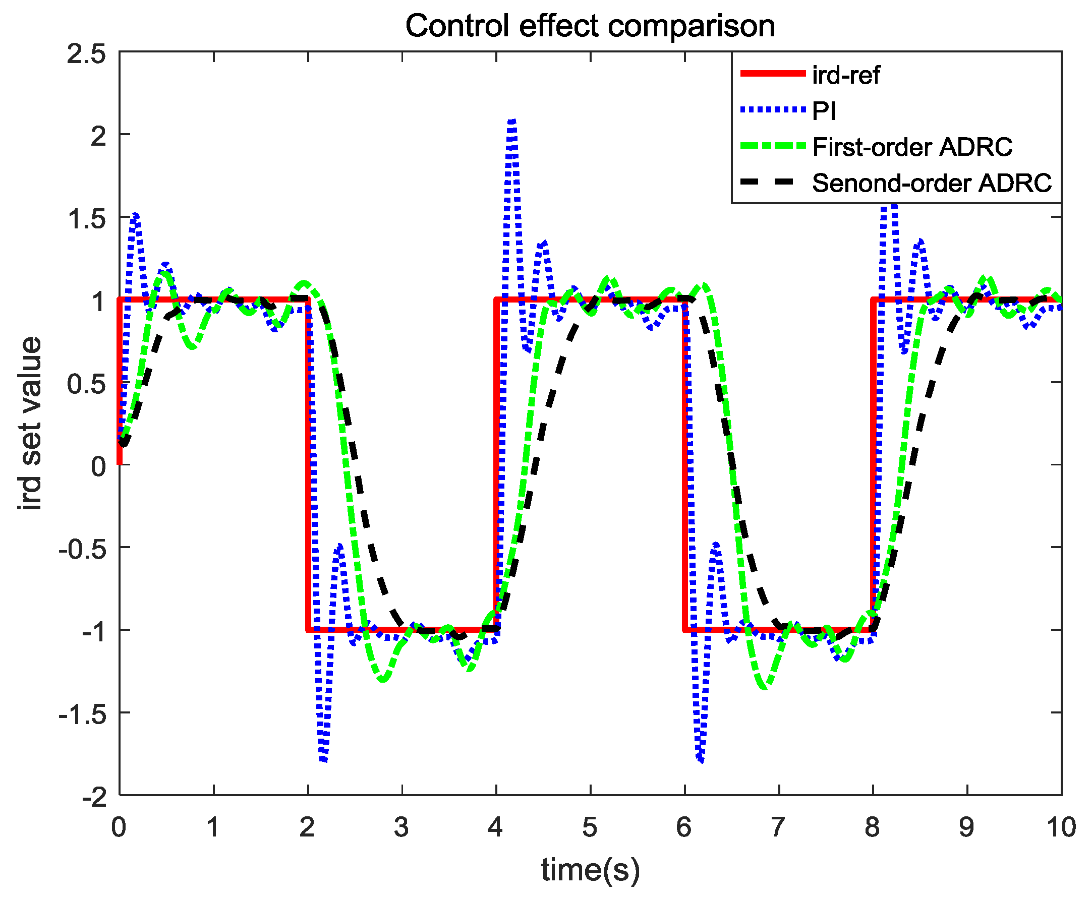
The waveform of the external disturbance is shown in Figure 13. It simulates the situation of large and small harmonic disturbance due to the switch and a nonlinear load. It can be seen from Figure 14 that, when there is external disturbance, the PI system has a large overshoot and a long adjustment time. The first-order ADRC can compensate the disturbance, but there was a slight overshoot and oscillation. The second-order ADRC, due to the role of the TD and ESO, keeps smoothly tracking the given signal. The prediction of the disturbance signal of ESO is shown as the black curve in Figure 13. It can be seen that the disturbance of the system is accurately estimated.
To the change in the external disturbance, the change of the parameters in the system is further added. Due to modeling error, equipment aging, parameter drift and other factors, the resistance of DFIG system decreased by 0.2 pu compared with the ideal model. Simulation and comparison of PI and ADRC control are shown in Figure 15.
As can be seen from Figure 15, PI control under the same control parameters, the control effect is significantly reduced when the system parameters change. The system overshoots and the adjustment time increases. This indicates that the robustness of the system is low when the parameters of the control model are changed. Compared to PI control, the first order ADRC has some robustness in the parameter drift. However, the control effect will be reduced which increase the overshoot and oscillation. Using second-order ADRC, the control is almost the same as before the changes occurred. This shows that the second-order ADRC controller has good robustness. In the case of insulation breakdown or equipment trouble, the system parameters will change more dramatically. At this time, the PI control may fluctuate or diverge, losing control of the system.
6. Conclusions
In order to improve the FRT capability of the DFIG, a second-order ADRC-based control strategy with integrated design of the flux damping method was proposed. Simulation and comparisons show that this method can effectively increase the robustness of the system and improve the system performance under a grid fault. Although the benchmark study provides satisfactory simulation results, the parameter tuning and optimizing of ADRC should be considered in future work.
Author Contributions
C.Y. and X.Y. conceived the idea, while Y.A.W.S. and X.Y. provided assistance with the development and implementation of the methods. C.Y. performed the simulations and analysed the data, with assistance from X.Y. and Y.A.W.S. C.Y. wrote the paper with editorial assistance from Y.A.W.S. and X.Y.
Acknowledgments
The authors would like to thank the National Natural Science Foundation of China under grant #61673053, the Beijing Natural Science Foundation under Grant #4162041, and the National Key R and D Program of China under grant #2017YFB0306403 for funding.
Conflicts of Interest
The authors declare no conflict of interest.
References
- Liu, Z.F.; Zhang, W.H.; Zhao, C.H.; Yuan, J.H. The economics of wind power in china and policy implications. Energies 2015, 8, 1529–1546. [Google Scholar] [CrossRef]
- Müller, S.; Deicke, M.; Doncker, R.W.D. Doubly fed induction generator systems for wind turbines. IEEE IAM 2002, 8, 26–33. [Google Scholar] [CrossRef]
- Mohseni, M.; Islam, S.M.; Masoum, M.A.S. Impacts of symmetrical and asymmetrical voltage sags on dfig-based wind turbines considering phase-angle jump, voltage recovery, and sag parameters. IEEE Trans. Power Electron. 2011, 26, 1587–1598. [Google Scholar] [CrossRef]
- Xiao, S.; Yang, G.; Zhou, H.; Geng, H. An lvrt control strategy based on flux linkage tracking for dfig-based wecs. IEEE Trans. Ind. Electron. 2013, 60, 2820–2832. [Google Scholar] [CrossRef]
- Erlich, I.; Wrede, H.; Feltes, C. Dynamic Behavior of Dfig-Based Wind Turbines during Grid Faults. In Proceedings of the Power Conversion Conference, Nagoya, Japan, 2–5 April 2007; pp. 1195–1200. [Google Scholar]
- Pannell, G.; Atkinson, D.J.; Zahawi, B. Minimum-threshold crowbar for a fault-ride-through grid-code-compliant dfig wind turbine. IEEE Trans. Energy Convers. 2010, 25, 750–759. [Google Scholar] [CrossRef]
- Lima, F.K.A.; Luna, A.; Rodriguez, P.; Watanabe, E.H.; Blaabjerg, F. Rotor voltage dynamics in the doubly fed induction generator during grid faults. IEEE Trans. Power Electron. 2010, 25, 118–130. [Google Scholar] [CrossRef] [Green Version]
- Shen, Y.; Cui, M.; Wang, Q.; Shen, F.; Zhang, B.; Liang, L. Comprehensive reactive power support of dfig adapted to different depth of voltage sags. Energies 2017, 10, 808. [Google Scholar] [CrossRef]
- Flannery, P.S.; Venkataramanan, G. A fault tolerant doubly fed induction generator wind turbine using a parallel grid side rectifier and series grid side converter. IEEE Trans. Power Electron. 2008, 23, 1126–1135. [Google Scholar] [CrossRef]
- Jalilian, A.; Naderi, S.B.; Negnevitsky, M.; Hagh, M.T.; Muttaqi, K.M. Controllable dc-link fault current limiter augmentation with dc chopper to improve fault ride-through of dfig. IET Renew. Power Gener. 2017, 11, 313–324. [Google Scholar] [CrossRef]
- Xiao, S.; Geng, H.; Zhou, H.; Yang, G. Analysis of the control limit for rotor-side converter of doubly fed induction generator-based wind energy conversion system under various voltage dips. IET Renew. Power Gener. 2013, 7, 71–81. [Google Scholar] [CrossRef]
- Ma, H.; Zhang, X.; Liu, X.; Xu, D. A novel flux damping control strategy of dfig based on voltage vector oriented. In Proceedings of the Power Electronics and Motion Control Conference, Harbin, China, 2–5 June 2012; pp. 2168–2172. [Google Scholar]
- Yang, C.; Yang, X.; Tong, C. An ADRC based Control Strategy for FRT Improvement of Wind Power Generation with Doubly Fed Induction Generator. Proc. CSEE 2018, 38, 2487–2495. [Google Scholar]
- Xu, L.; Wang, Y. Dynamic modeling and control of dfig-based wind turbines under unbalanced network conditions. IEEE Trans. Power Syst. 2007, 22, 314–323. [Google Scholar] [CrossRef]
- Costa, J.P.D.; Pinheiro, H.; Degner, T.; Arnold, G. Robust controller for dfigs of grid-connected wind turbines. IEEE Trans. Ind. Electron. 2011, 58, 4023–4038. [Google Scholar] [CrossRef]
- Kim, K.H.; Jeung, Y.C.; Lee, D.C.; Kim, H.G. Lvrt scheme of pmsg wind power systems based on feedback linearization. IEEE Trans. Power Electron. 2012, 27, 2376–2384. [Google Scholar] [CrossRef]
- Chakib, R.; Cherkaoui, M.; Essadki, A. Stator flux control by active disturbance rejection control for dfig wind turbine during voltage dip. Int. J. Circuits Syst. Signal Process. (USA) 2015, 9, 281–288. [Google Scholar]
- Tohidi, A.; Hajieghrary, H.; Hsieh, M.A. Adaptive disturbance rejection control scheme for dfig-based wind turbine: Theory and experiments. IEEE Trans. Ind. Appl. 2016, 52, 2006–2015. [Google Scholar] [CrossRef]
- Blasko, V.; Kaura, V. A new mathematical model and control of a three-phase ac-dc voltage source converter. IEEE Trans. Power Electron. 2002, 12, 116–123. [Google Scholar] [CrossRef]
- Han, J. From pid to active disturbance rejection control. IEEE Trans. Ind. Electron. 2009, 56, 900–906. [Google Scholar] [CrossRef]
- Han, J. The Technique for Estimating and Compensating the Uncertainties: Active Disturbance Rejection Control Technique; National Defense Industry Press: Beijing, China, 2008. [Google Scholar]
- Gao, Z. Scaling and bandwidth-parameterization based controller tuning. In Proceedings of the 2003 American Control Conference, Denver, CO, USA, 4–6 June 2003; Volume 6, pp. 4989–4996. [Google Scholar]
- Sun, D. Comments on active disturbance rejection control. IEEE Trans. Ind. Electron. 2007, 54, 3428–3429. [Google Scholar]
- Wang, L.; Li, Q.; Tong, C.; Yin, Y. Overview of active disturbance rejection control for systems with time-delay. Control Theory Appl. 2013, 30, 1521–1533. [Google Scholar]
- Herbst, G. Practical active disturbance rejection control: Bumpless transfer, rate limitation, and incremental algorithm. IEEE Trans. Ind. Electron. 2016, 63, 1754–1762. [Google Scholar] [CrossRef]
- He, Y.; Hu, J.; Xu, L. The Grid-Connected Operations Control of Wind-Turbine Driven Doubly Fed Induction Generators; China Electric Power Press: Beijing, China, 2012. [Google Scholar]
Figure 1.
The equivalent circuit of the DFIG.

Figure 2.
The control diagram of the RSC.

Figure 3.
The control diagram of the GSC.

Figure 4.
The flow chart of the integrated design of ADRC and flux damping method.

Figure 5.
The schematic diagram of the flux damping current.

Figure 6.
The schematic diagram of ADRC.

Figure 7.
RSC control structure with ADRC.

Figure 8.
Disturbance signal and ESO’s predictions.

Figure 9.
Step response under first-order ADRC and second-order ADRC.

Figure 10.
Symmetrical 60% voltage dip case: (a) DC bus voltage; (b) rotor current; and (c) electromagnetic torque.
Figure 10.
Symmetrical 60% voltage dip case: (a) DC bus voltage; (b) rotor current; and (c) electromagnetic torque.


Figure 11.
Symmetrical 80% voltage dip case: (a) DC bus voltage; (b) rotor current; and (c) electromagnetic torque.
Figure 11.
Symmetrical 80% voltage dip case: (a) DC bus voltage; (b) rotor current; and (c) electromagnetic torque.


Figure 12.
Asymmetrical 80% voltage dip case: (a) DC bus voltage and (b) electromagnetic torque.

Figure 13.
External disturbances and ESO prediction results.

Figure 14.
Comparison of control effects under external disturbance.

Figure 15.
Comparison of control effects under the system model parameters change.


Table 1.
Simulation parameters.
| Parameters | Value |
|---|---|
| Rated power (MW) | 1.5 |
| Stator voltage (V) | 575 |
| Stator resistance (pu) | 0.023 |
| Stator inductance (pu) | 0.18 |
| Rotor resistance (pu) | 0.016 |
| Rotor inductance (pu) | 0.16 |
| mutual inductance (pu) | 2.9 |
| Initial slip | 0.2 |
| DC voltage setting value (V) | 1150 |
| Wind speed (m/s) | 10 |
Table 2.
Performance index comparison for the symmetrical 60% voltage dip case.
| Performance Index | Vector PI Control | PI with Flux Damping | ADRC with Flux Damping |
|---|---|---|---|
| VDC_max (V) | 1392 | 1296 | 1229 |
| Ir_max (pu) | 2.6 | 1.79 | 1.59 |
| Tm_ts (s) | 0.08 | 0.07 | 0.06 |
Table 3.
Performance index comparison for the symmetrical 80% voltage dip case.
| Performance Index | Vector PI Control | PI with Flux Damping | ADRC with Flux Damping |
|---|---|---|---|
| VDC_max (V) | 3580 | 1620 | 1280 |
| Ir_max (pu) | 3.38 | 2.38 | 1.96 |
| Tm_ts (s) | >0.1 | >0.1 | 0.06 |
© 2018 by the authors. Licensee MDPI, Basel, Switzerland. This article is an open access article distributed under the terms and conditions of the Creative Commons Attribution (CC BY) license (http://creativecommons.org/licenses/by/4.0/).
Share and Cite
MDPI and ACS Style
Yang, C.; Yang, X.; Shardt, Y.A.W. An ADRC-Based Control Strategy for FRT Improvement of Wind Power Generation with a Doubly-Fed Induction Generator. Energies 2018, 11, 1150. https://doi.org/10.3390/en11051150
AMA Style
Yang C, Yang X, Shardt YAW. An ADRC-Based Control Strategy for FRT Improvement of Wind Power Generation with a Doubly-Fed Induction Generator. Energies. 2018; 11(5):1150. https://doi.org/10.3390/en11051150
Chicago/Turabian StyleYang, Chenxing, Xu Yang, and Yuri A. W. Shardt. 2018. "An ADRC-Based Control Strategy for FRT Improvement of Wind Power Generation with a Doubly-Fed Induction Generator" Energies 11, no. 5: 1150. https://doi.org/10.3390/en11051150
Note that from the first issue of 2016, this journal uses article numbers instead of page numbers. See further details here.