1. Introduction
The exploration and utilization of nature sources in deep sea have become an important issue with the increasing demand of power source. Multiphase pump is a widely used piece of equipment in petroleum industry for offshore plant, which pressurizes and transports the mixture of oil and gas. However, due to the complicated interactions between the liquid phase and gas phase, the efficient transporting of multiphase flow still requires further investigation.
The technique of multiphase pump was firstly proposed and tested in 1990s, and it can be classified into two major categories, including screw pump and rotodynamic pump. The screw pump transports the fluid by the volume variation of seal chamber between screws and bushing, which is applied in the condition of high gas volume fraction and is sensitive to the solid particles. Dal Porto et al. [
1] introduced the trial of twin-screw pumps in Gulf of Mexico and Alberta in Canada. Field applications validated the reliability of multiphase pumps in handling slugs, but the low efficiency of this type pump restricted their wide application. Rabiger et al. [
2] carried out theoretical and experimental analysis on a multiphase screw pump with high gas volume fractions, and leakage flows through the circumferential gaps were observed. For the other type of rotodynamic pump, it transports energy to the fluid by the rotating impeller, and it has advanced performance because of its high efficiency and pumping of particle. Cao et al. [
3] carried out experiment study on the performance of rotodynamic multiphase pump. The experimental results showed that the pump could operate in a wide range with the highest efficiency of 44.0%. The flow fileds inside the rotodynamic multiphase pump had been studied by means of high-speed photography technique [
4,
5]. Experimental observation showed that the mean diameter of the bubbles at the inlet section would increase when the inlet gas volume fraction increased, while the mean diameter decreased with the increasing of rotation speed. Typical flow patterns, including isolated bubbles flow, bubbly flow, gas pocket flow, and segregated flow, appeared in sequence with the increasing of inlet gas volume fraction. Among these flow patterns, the gas pocket flow was the most common one and had significant influence on the hydraulic performance of the multiphase pump [
6]. It was found that the gas pocket would form at the suction surface and then moved towards the pressure surface downstream.
The experimental research of hydraulic machinery is always time-consuming and costly due to its complexity, and the Computational Fluid Dynamics (CFD) method has become an effective tool in the investigation [
7,
8,
9]. When compared with single phase flow, the numerical simulations of multiphase flow are much more complicated in account of the interphase interactions between liquid phase and gas phase. Yu et al. [
10] compared the numerical results of homogeneous model and two-fluid model, and found that the latter one was more reasonable and accurate because the effect of interphase forces was taken into consideration. To study the magnitude of different interphase forces, four types of forces were considered overall, involving drag force, lift force, virtual mass force, and turbulent dispersion force in the numerical simulations [
11,
12]. Results showed that the drag force was dominant inside the impeller, while the turbulent dispersion force was almost negligible. In addition, the lift force and virtual mass force were larger or smaller than the drag force, depending on inlet gas volume fraction and location.
Because of the importance of rotodynamic multiphase pump in petroleum industry, various studies have been conducted to optimize its structure and improve hydraulic performance. Since the nonlinear relation between geometry parameters and hydraulic performance is complex, various optimization methods have been introduced for the study of multiphase pump, such as genetic algorithm [
13,
14,
15], response surface method [
16,
17], and the central composite method [
18]. Zhang et al. [
13] developed a multi-objective optimal method by combining the non-dominated sorting genetic algorithm-II (NSGA-II) and artificial neural network (ANN), and the pressure rise and efficiency of optimized pump were improved by 10% and 3%, respectively, in comparison of the original pump. Kim et al. [
16] applied the design of experiment (DOE) technique to organize the optimization procedure, and the optimization results were obtained by means of response surface method (RSM). By optimization, the pressure rise and the efficiency were increased by 30.9 kPa and 1.9%, respectively. Numerical results of the internal flow fields indicated that the optimized pump could suppress the non-uniform flow components.
The above optimization methods, which can be collectively called intelligent algorithms, always require hundreds of test cases and consume large amount of resources. The orthogonal method is introduced to reduce the cost in the present research, which was developed by Byrne and Taguchi [
19]. According to the orthogonal method, the parameters are arranged to meet the principle of orthogonality, and hence the number of test cases can be reduced to achieve efficient optimization. Many investigations [
20,
21,
22,
23,
24] have validated the reliability of the orthogonal method on the optimization of hydraulic machinery.
When compared with various studies on optimization, the design method for rotodynamic multiphase pump is relatively rare. The pump geometry is mainly developed according to previous experience, which is highly sensitive for different situations. Cao et al. [
3] have proposed a hydrodynamic design method for the impeller of multiphase pump by means of a combined approach of inverse design and CFD analysis. According to this method, the geometry of impeller was determined by specified velocity torque distribution. The three-dimensional hydraulic method was also employed by Zhang et al. [
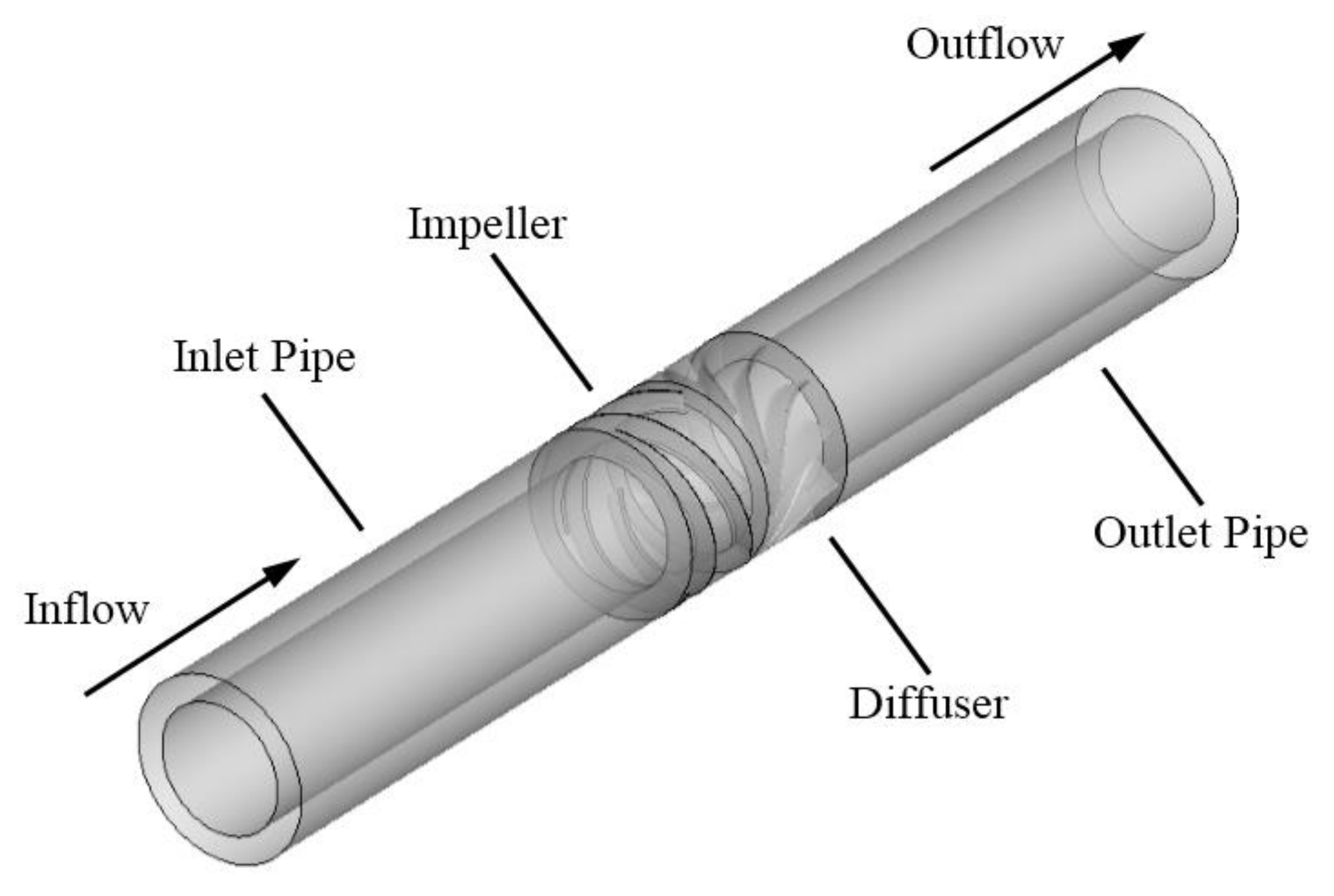
25], and it was effective to suppress the performance decline under large flow rate. For rotodynamic multiphase pump, a diffuser is always equipped after an impeller to recover the kinetic energy from fluid and adjust the flow direction. The impact at diffuser inlet can be reduced and the flow pattern inside diffuser can be promoted when the geometry at the impeller outlet and diffuser inlet is matched. However, the previous design method mainly focuses on the impeller and the design for diffuser remains empirical. In the present research, a design method for the impeller and diffuser of the rotodynamic multiphase pump is proposed based on the controllable blade angle, and the geometry parameters are optimized by the means of the orthogonal method.
2. Design Method Based on Controllable Blade Angle
Traditionally, the impeller and diffuser of rotodynamic multiphase pump are designed empirically, which requires a large amount of trail tests. In the current study, a design method based on controllable blade angle is introduced, which derives from the design method of inlet guide vanes in centrifugal pump [
26]. According to the proposed design method, the blade geometry can be determined by the distribution of blade angle along meridional flow.
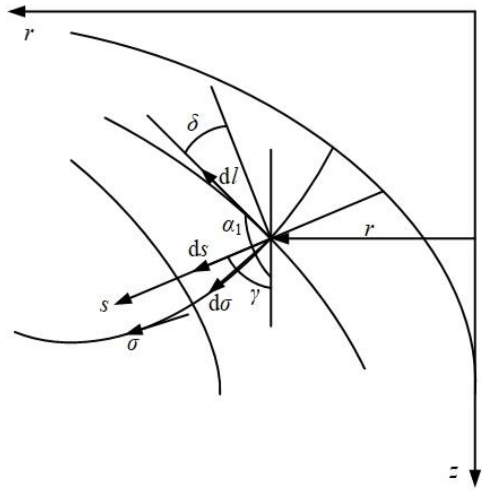
First, the meridional flow is determined by means of streamline curvature method. The gradient equation of meridional velocity
cm along the quasi-orthogonal curve
s can be expressed by:
where
l and
r denote the meridional streamline and the radius,
α1 is the angle between the tangential of meridional streamline and the axial line, and
δ is the angle between the normal of quasi-orthogonal curve and the tangential of meridional streamline, and
χ is the blockage coefficient, as shown in
Figure 1.
The general solution of the above gradient equation is as follows:
where
cmc is a constant determined by the following continuity:
where
Q is the volume flow rate, and subscripts
shr,
hub denote the shroud and the hub, respectively.
On the assumption that the flow rates are equal inside each sub-flow channel, the result of meridional velocity can be calculated by solving the Equation (1) in order to determine the flow net. Then, the three-dimensional geometry of blade can be determined according to the bone line differential equation:
where
θ and
β are wrap angle and blade angle, respectively.
The above flow equations can be referred in Ref. [
26] for detail. Since the meridional streamline
l and the radius
r can be determined by the solved flow net, the key factor of hydraulic design is to determine the distribution of blade angle
β along the meridional streamline. The blade angle distribution along the meridional streamline from inlet to outlet can be normalized, as follows:
where
x denotes the relative meridional streamline, and values of 0 and 1 represent the leading edge and trailing edge, respectively.
β0 is the blade angle at the leading edge, and ∆
β =
β1 −
β0 is the difference between the blade angle at trailing edge and the leading edge.
In the present design method, polynomial functions are employed for the blade of impeller and diffuser. For blade of impeller, a normalized fourth-order polynomial function is applied since there are four given conditions and one unknown condition. It can be expressed by:
where
a,
b,
c,
d and
e are coefficients, and five conditions are required to calculate these coefficients.
- (1)
The blade angle at the leading edge:, corresponding to ;
- (2)
The blade angle at the trailing edge:, corresponding to ;
- (3)
The non-incidence condition at the leading edge:, corresponding to ;
- (4)
The Kutta-Joukowsky condition at the trailing edge:, corresponding to ;
- (5)
The value of f(x) at middle point of relative meridional streamline x = 0.5 is given as k.
Taking account of the above five conditions, the coefficients of
f(
x) can be obtained, as follows:
According to Equation (8), the normalized fourth-order polynomial function f(x) can be determined by the given value of k.
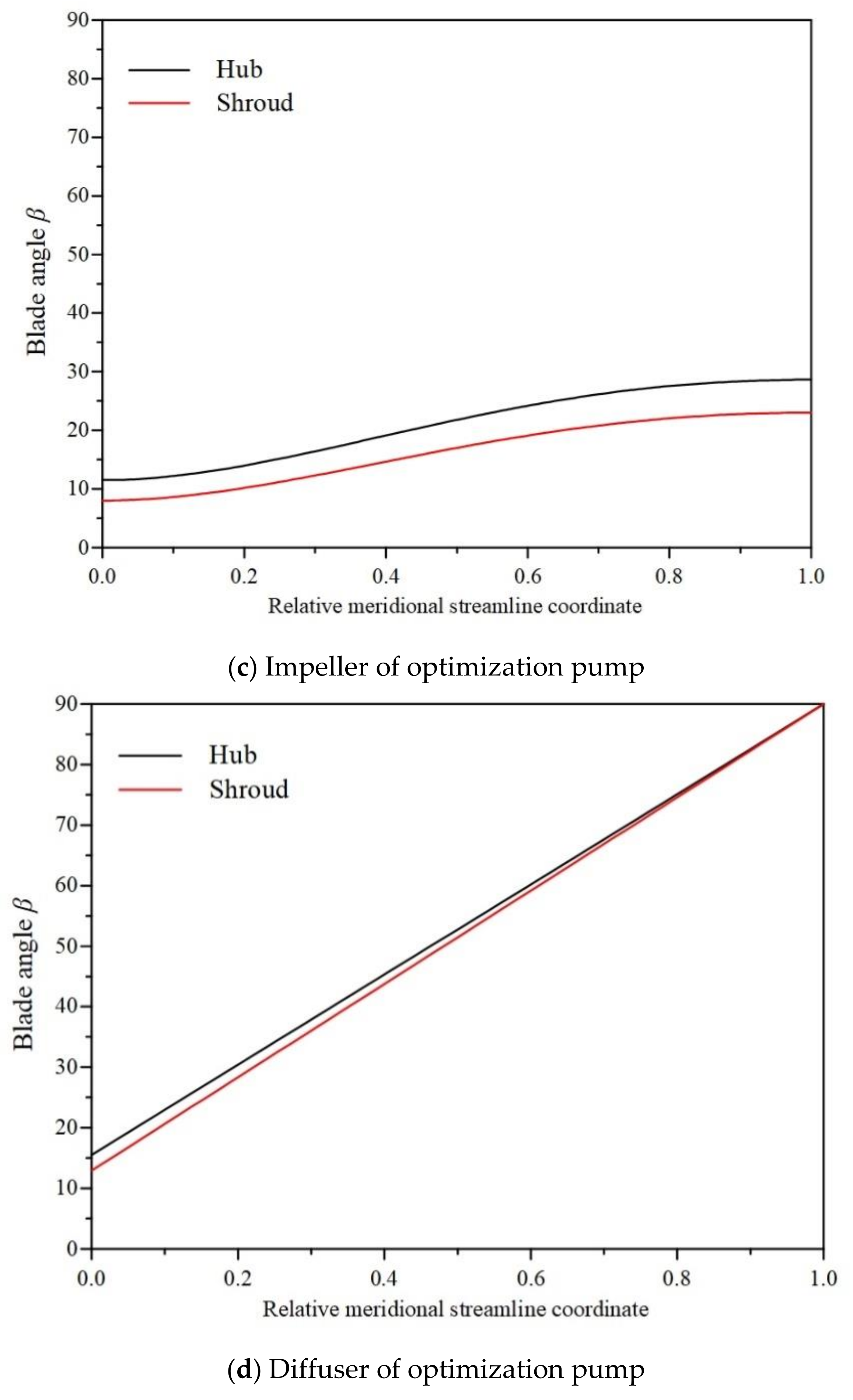
For diffuser, the normalized polynomial function is simply set as proportional function of f(x) = x, which is a first-order polynomial function, because uniform blade loading is required to suppress flow separation due to the powerful rotation of inflow.
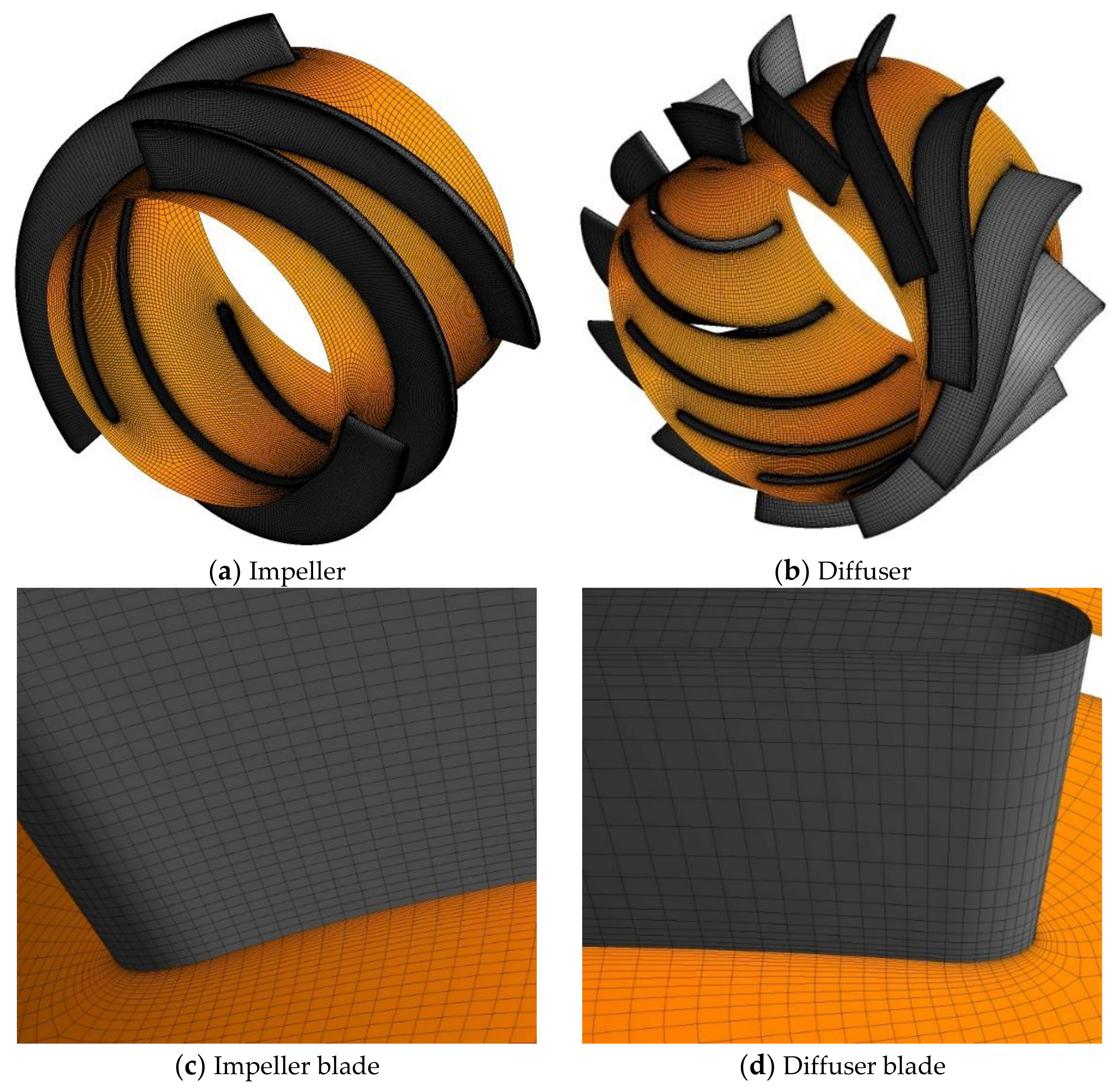
Generally, the geometry parameters at the hub and shroud of blade are given as initial parameters, including blade angles βIh0, βIs0, βIh1, βIs1, βDh0, βDs0, βDh1, βDs1, and k-coefficient kh, ks, where the subscript I and D denote the impeller or diffuser, h and s denote the hub and shroud, 0 and 1 denote the leading edge and the trailing edge, respectively.
Additional conditions should be added to determine these ten geometry parameters, as follows:
- (1)
Identical wrap angle at impeller outlet should be met to suppress the gas-liquid separation due to centrifugal force, which satisfies the following equation:
- (2)
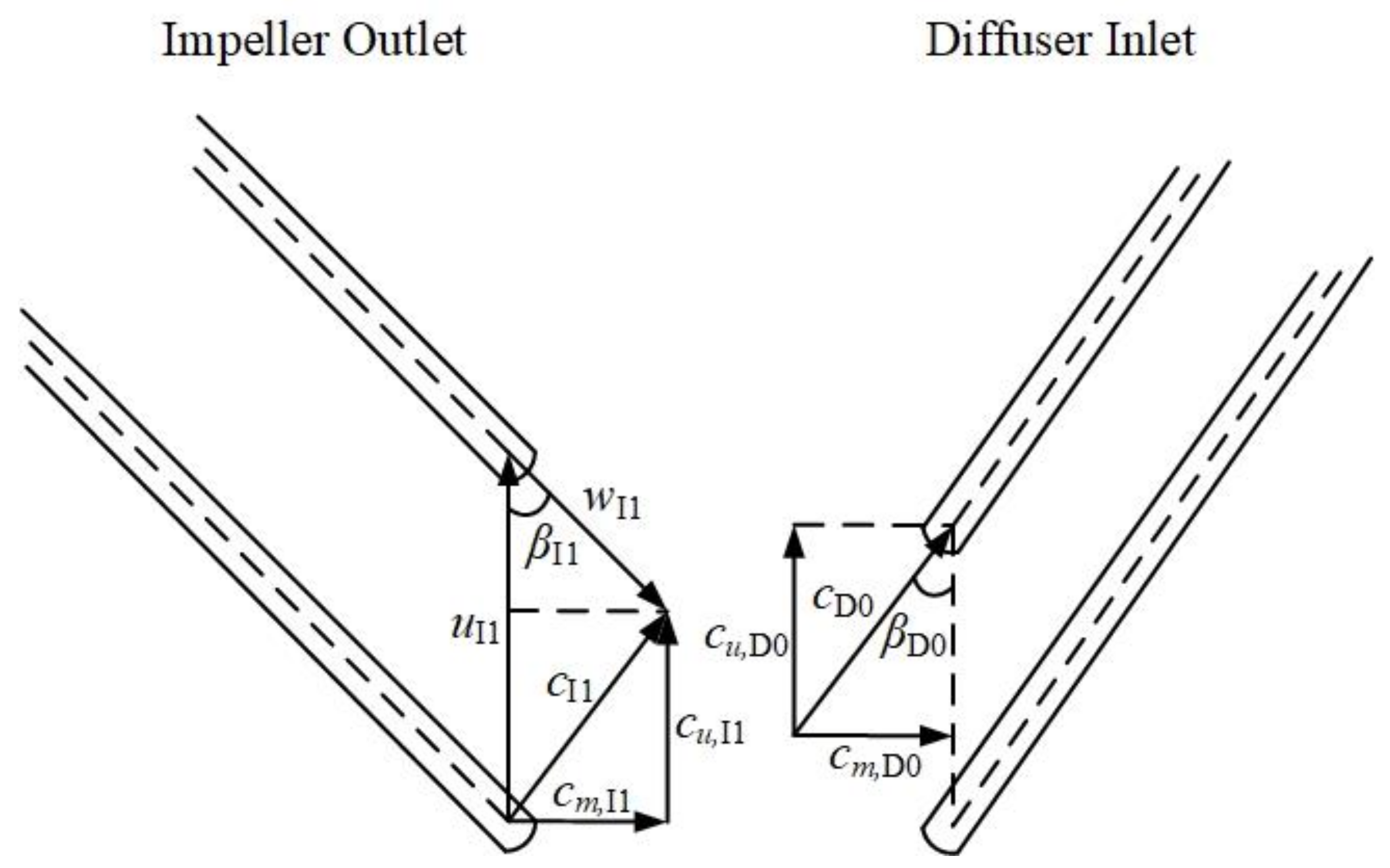
Supposing uniform velocity moment between impeller outlet and diffuser inlet because of none extra velocity moment in the vaneless region,
βDh0 and
βDs0 can be determined, as shown in
Figure 2:
where
c,
w,
u are absolute velocity, relative velocity and circumferential velocity, respectively.
cu and
cm are the circumferential and meridional component of absolute velocity.
- (3)
Axial outflow for diffuser is required, so the values of βDh1 and βDs1 are set as 90°.
According to the above additional conditions, only five geometry parameters need to be given initially for this design method, which are βIh0, βIs0, βIs1, kh, and ks. So far, the hydraulic design method for the blades of impeller and diffuser has been completed, and the initial given parameters of βIh0, βIs0, βIs1, kh, and ks will be optimized in the present research.


