Vacuum Exhaust Process in Pilot-Scale Vacuum Pressure Swing Adsorption for Coal Mine Ventilation Air Methane Enrichment

1
School of Energy and Environmental Engineering, University of Science and Technology Beijing, Beijing 100083, China
2
Beijing Higher Institution Engineering Research Center of Energy Conservation and Environmental Protection, Beijing 100083, China
3
College of Biochemical Engineering, Beijing Union University, Beijing 100023, China
*
Authors to whom correspondence should be addressed.
Energies 2018, 11(5), 1030; https://doi.org/10.3390/en11051030
Submission received: 1 March 2018
/
Revised: 28 March 2018
/
Accepted: 23 April 2018
/
Published: 24 April 2018
(This article belongs to the Special Issue Unconventional Natural Gas (UNG) Recoveries 2018)
Abstract
:Recovery and treatment of methane from coal mine ventilation air methane (VAM) with cost-effective technologies have been an ongoing challenge due to low methane concentrations. In this study, a type of coconut shell-based active carbon was employed to enrich VAM with a three-bed vacuum pressure swing adsorption unit. A new vacuum exhaust step for the VPSA process was introduced. The results show that the vacuum exhaust step can increase the methane concentration of the product without changing adsorption and desorption pressure. Under laboratory conditions, the concentration of product increased from 0.4% to 0.69% as the vacuum exhaust ratio increased from 0 to 3.1 when the feed gas concentration was 0.2%. A 500 m³/h pilot-scale test system for VAM enrichment was built rendering good correlation with the laboratory results in terms of the vacuum exhaust step. By using a two-stage three-bed separation unit, the VAM was enriched from 0.2% to over 1.2%.
1. Introduction
Coal mine methane is a form of natural gas extracted from coal beds, which is formed together with coal during coalification. Coal mine methane is not only an important energy resource but also a greenhouse gas [1,2,3]. As a greenhouse gas, it is over 20 times more effective in trapping heat than carbon dioxide, and it exists in the atmosphere for approximately 9–15 years. Methane emitted from coal mines makes up approximately 8% of the world’s anthropogenic methane emissions, which comprises 17% of all anthropogenic greenhouse gas emissions [4].
Most fugitive coal mine methane is emitted as mine ventilation air methane (VAM) at low concentrations of below 1%, which makes up 70% of the methane emissions in the coal mining processes. China is the world’s leading emitter of coalmine methane; it accounts for 45% of world’s VAM emissions [5], with a VAM concentration lower than 0.25% [6]. The low concentration of VAM is considered as a major challenge for its utilization and mitigation.
There are several technologies for destroying or utilizing VAM. VAM can be used as a supplemental fuel for various combustion systems such as boilers, engines and turbines to provide heat or power at mine sites. However, this only contributes a small percentage of the total fuel used for conventional gas turbines and gas engines. VAM can also be used as a principal fuel for flow reversal oxidation reactors including the thermal flow reversal reactor (TFRR) [7,8,9] and catalytic flow reversal reactor (CFRR) [4,10], and catalytic lean burn gas turbines [4]. Flow reversal oxidation units cannot work efficiently and steadily when the methane concentration is too low. Warmuzinski [11] showed that no heat can be recovered when the methane concentration is 0.2%. Most VAM utilization technologies require a 0.5% methane concentration as the minimum concentration for stable working conditions [7]. Lean-burn combustion turbine technologies can generate power, operating on a higher methane concentration (between 0.8% and 1.6%), such as the carbureted gas turbine (CGT) by Energy Developments Limited (EDL) of Australia, the catalytic combustion gas turbine (CCGT) by CSIRO [12], and the micro-turbine by Ingersoll Rand [13]. Lean-burn combustion turbine technologies may require additional supplementary fuel for stable operation depending on the VAM concentration [14].
Upgrading the concentration of VAM is a major solution for attaining the minimum methane concentration that is required by the above technologies. Among the common methods for VAM enrichment, adsorption is one of the best ways. There has been a wide range of studies on pressure swing adsorption (PSA), including discussions about methane enrichment in the adsorption phase [15,16,17,18,19] or effluent gases [20,21,22,23]. In the PSA process, methane is often enriched in the adsorption phase by using carbon material. Su [24,25] utilized honeycomb monolithic carbon fiber composite (HMCFC) as the adsorbent for methane enrichment, achieving a methane adsorption capacity of 1.5 mmol/g (298 K, 1 atm). VAM can be enriched to 5 times higher than the feed gas at the end of the vacuum step, unfortunately previous work studied only one adsorption bed. Ouyang [26] modified coconut shell-based carbon adsorbents, the separation factor of CH4/N2 is 6.18, showing that VAM can be enriched from 0.42% to 1.09% by vacuum pressure swing adsorption (VPSA). In previous work, our group modified coconut shell-based carbon and showed that aqueous ammonia modification improved equilibrium and the dynamic selectivities of CH4 by 11.7 and 14.9%, respectively [27], and also upgraded the VAM from 0.3% to 0.75% using coconut shell-based carbons in the VPSA process [28].
Nevertheless, the assessment of adsorbents in VPSA is still at the laboratory stage, and few scholars have focused on increasing the methane concentration through improvement in the VPSA process. In the conventional PSA process, there are often two steps for increasing the concentration of a heavy component. One is a high-pressure purge with a concentrated heavy component (such as CO2 capture [29,30], methane enrichment by active carbon [15,18]), although this process needs an additional compressor. The other step is co-current depressurization; this step allows the low concentration heavy component gas to flow out from the top of the adsorption bed [31,32,33]. However, in vacuum pressure swing adsorption the adsorption pressure is very low (roots blowers often operate at a pressure lower than 50 kPa), and after equalization the pressure is often lower than the atmosphere pressure. The co-current depressurization cannot be carried out. Therefore, drawbacks exist for both steps in practical applications.
In this paper, a new vacuum exhaust step for the VPSA process employed with coconut shell activated carbon is introduced, with the purpose of obtaining a more cost-effective way for VAM recovery. A pilot plant is correspondingly built. Comparisons with experimental results as well as practically-oriented analyses for further applications will be shown.
2. Experiment Section
2.1. Experimental Facility
In this study, the adsorption pressure was no more than 150 kPa (abs) and the desorption pressure was approximately 14 kPa (abs). The flow rate of the feed gas was approximately 5 L/min. The product was extracted from the adsorption bed by a membrane vacuum pump. The specifications of the adsorber are: 46 mm in internal diameter and 420 mm in length. The adsorber were packed with properly selected coconut shell activated carbon. The methane concentration was measured with an infrared methane analyzer QGS-08C (Beijing BAIF-Maihak Analytical Instrument Co., Ltd., Beijing, China). The flow rates were measured with a digital mass flow controller (Beijng Sevenstar Flow Co., Ltd., Beijing, China)
Figure 1 shows a schematic diagram of a laboratory three-bed adsorption unit for enrichment of VAM. VAM can be considered as a mixture of CH4 and air and in this study, the methane concentration of feed gas is 0.2 vol %. VAM was stored in a gas bag. This unit operates the separation process cycle with the help of an Omron PLC that controls the solenoid valve switching.
2.2. VPSA Process Cycle
Two six-step VPSA cycles (cycle a and cycle b) were used in this study, and the six steps are as follows: adsorption (AD), pressure equalization (PE↓), vacuum exhaust (VE), vacuum (VA), pressure equalization (PE↑), and pressurization (PR). The cycle configuration of 1/3 cycle is shown in Figure 2, and the time schedule for the VPSA process is also shown in Table 1. The six steps are described below.
Adsorption (AD): pressure of no more than 150 kPa abs was used. VAM is passed through the adsorption bed upwards, methane is selectively adsorbed in the bed of activated carbon, and the mixture of nitrogen and oxygen (with a small percentage of methane) leaves the bed and is sent to the buffer vessel and continuously released to the atmosphere.
Pressure equalization (PE↓): after the adsorption step, low methane concentration gas flows from the high pressure bed to a low pressure bed on the top.
Vacuum exhaust (VE): after step PE↓ gas was vacuumed from the top of the bed. In cycle a, the gas is emission to the atmosphere. In cycle b, the exhaust gas is flow to the feed gas to recycle. The different between cycle a and cycle b is whether there has an exhausted gas reflow step. In cycle a, the vacuum exhausted gas is emission to the atmosphere, while in cycle b the vacuum exhausted gas is recycled from the dotted line in the bottom left corner of Figure 1 to reflow and mix with the feed gas. In this study, the vacuum exhaust ratio was defined as:
Vacuum (VA): produced from the desorption phase by vacuum pump from the bottom of bed 1. The adsorber vessel’s pressure is lowered to about 14 kPa abs.
Pressure equalization (PE↑): after the vacuum step, low methane concentration gas flows from high pressure bed 1 to the low pressure bed on the top.
Pressurization (PR): effluent gas is used; the effluent gas is charged to the top of the adsorber vessel from the buffer to raise the pressure.
2.3. Pilot Separation Device
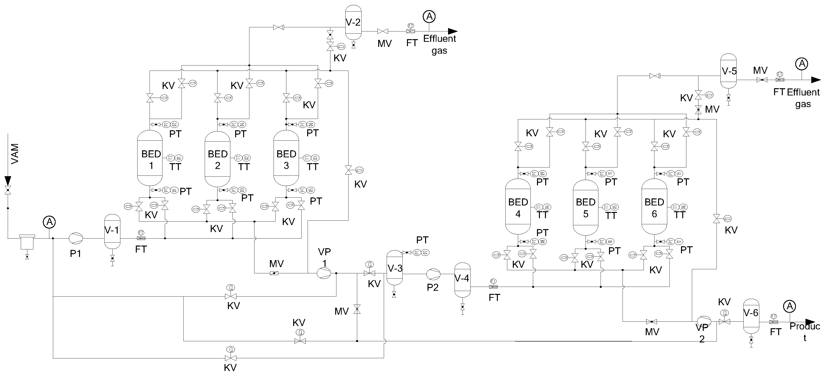
The pilot plant was installed at Julong Mine, Jizhong Energy Handan Mig., Handan, China. Figure 3 shows the system schematics of the pilot plant for VAM recovery by vacuum pressure swing adsorption (VPSA), and a photo of the pilot plant is shown in Figure 4. The plant includes a two-stage VPSA separation system with three parallel connected adsorption beds. The two-stage separation device was able to operate independently. The size of the two-stage separation device’s adsorption beds was φ1000 mm × 1840 mm and φ550 mm × 1440 mm, respectively. The adsorption beds were filled with active carbon, which is the same as the laboratory system.
The feed gas was a mix of VAM and coal mine methane (CMM), the methane concentration of the feed gas could be regulated by adjusting the flow rate of VAM and CMM. The feed gas is compressed by a roots blower (P1) and transferred to the adsorption bed of the first stage-stage separation unit. The methane-rich gas is vacuumed by vacuum pump (VP1). Then, the methane-rich gas is transferred to the second separation unit by roots blower (P2). The product is obtained from the vacuum pump (VP2). To ensure the regular work of the roots blower (P2), a big gas buffer (V-3) was set between the roots blower (P2) and vacuum pump (VP1), and a bypass valve was employed to link the feed gas inlet and the gas buffer (V-3). The flow quantity of the two roots blowers were 8.4 m3/min and 3.36 m3/min, respectively.
Inductors and sensors were connected to the adsorption bed, pipeline and PLC (with a computer), to monitor the change in the adsorption process and collect data. PLC programs were developed to analyze the data and control the pneumatic valves in the process. Methane concentration in feed gas, effluent gas and product gas were analyzed by the methane sensor of GJC4, the flow rate of the gas was measured by a vortex flowmeter (FI).
2.4. Adsorbent Isotherm Measurement
The adsorbents selected was coconut shell active carbon. Adsorption equilibrium analyses at different temperatures were carried out with a Quantachrome Instruments Auotosorb-1 Sorptometer, which used volumetric measurement techniques. The surface area of AC was carried out by use of nitrogen isotherm at 77 K. The pore size distribution ranged from 0.3 to 1.5 nm and from 1.5 to 10 nm and were obtained using the non-local density functional theory (NLDFT) method based on the adsorption isotherms of CO2 at 273 K and N2 at 77 K, respectively [29,30].
3. Results and Discussion
3.1. Adsorbent Analyses
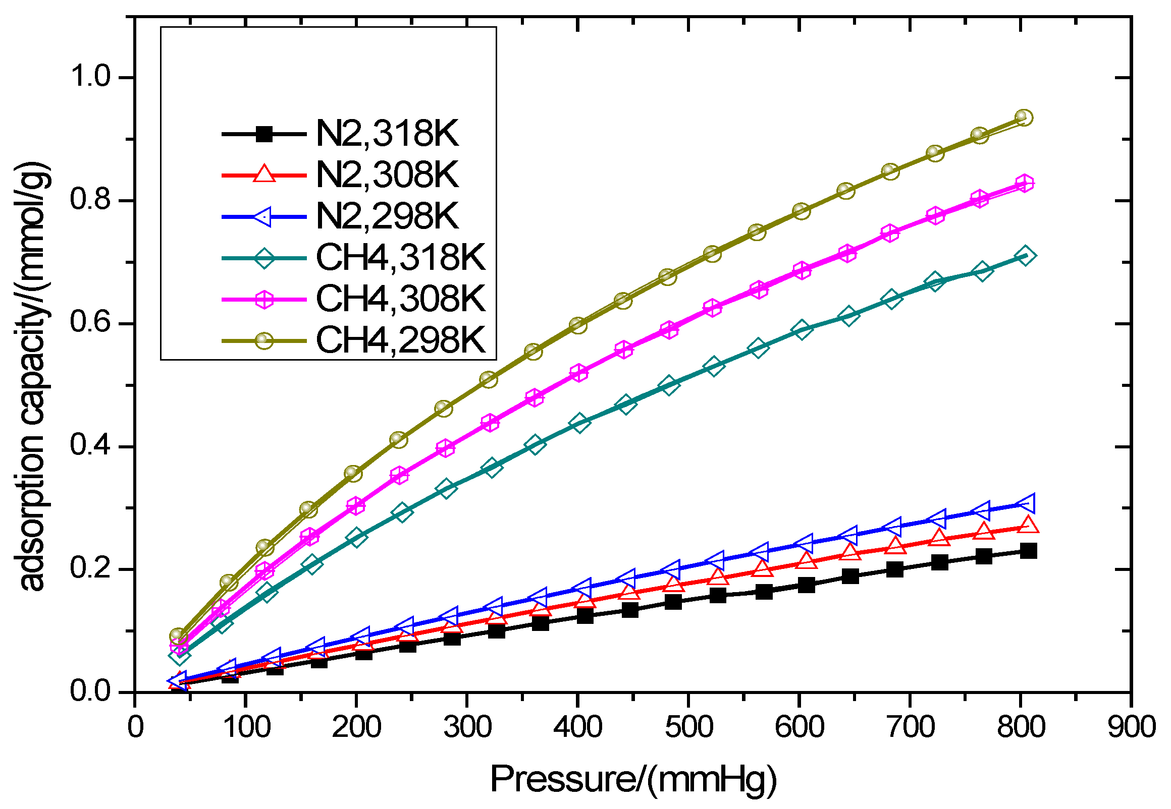
As the isotherm of nitrogen and oxygen on active carbon is almost the same [19], VAM can be considered as methane and nitrogen. In this study, the isotherms of methane and nitrogen at 298 K, 308 K and 318 K are shown in Figure 5. The isotherms can be expressed by the Langmuir equation [29,33].
where q (mmol/g) is adsorption capacity at the equilibrium gas pressure (P, mmhg), qm (mmol/g) is the maximum adsorption capacity and b (mmhg−1) is the Langmuir constant. The Langmuir constants of each adsorbent are given in Table 2. Results show methane adsorption capacity at 1 atm, 298 K is about 0.91 mol/kg. The equilibrium selectivity [34] of methane to nitrogen was 5.12 at 298 K. The results show that this active carbon is a good adsorbent for methane recovery from VAM or coal mine gas.
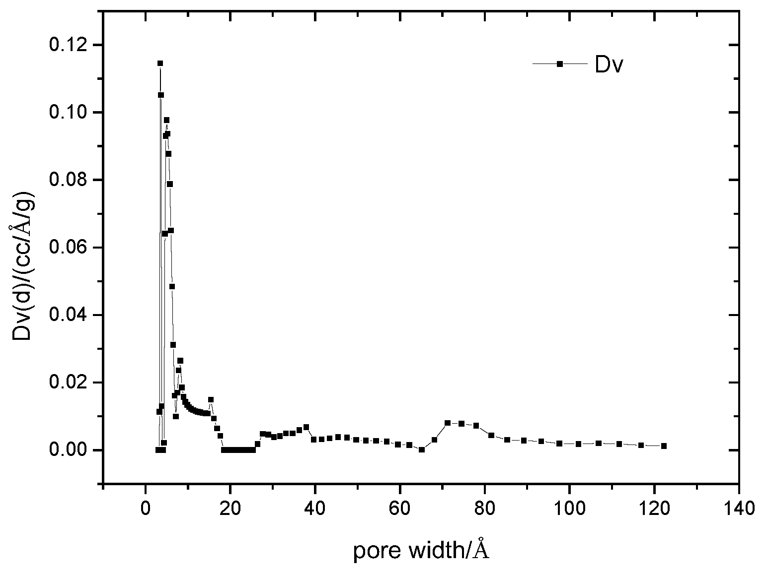
Characteristics of AC are presented in Table 3, with the pore size distribution given by NFLDFT as shown in Figure 6. The result shows this adsorbent has a highly developed micropore structure. The BET surface is 1155 m2/g. Figure 6 shows that most of the pore diameters are below 20 Å, and it had considerably more micropore volume with a pore diameter of 7 Å.
3.2. Effect of Vacuum Exhaust Process on Vacuum Pressure Swing Adsorption Performance
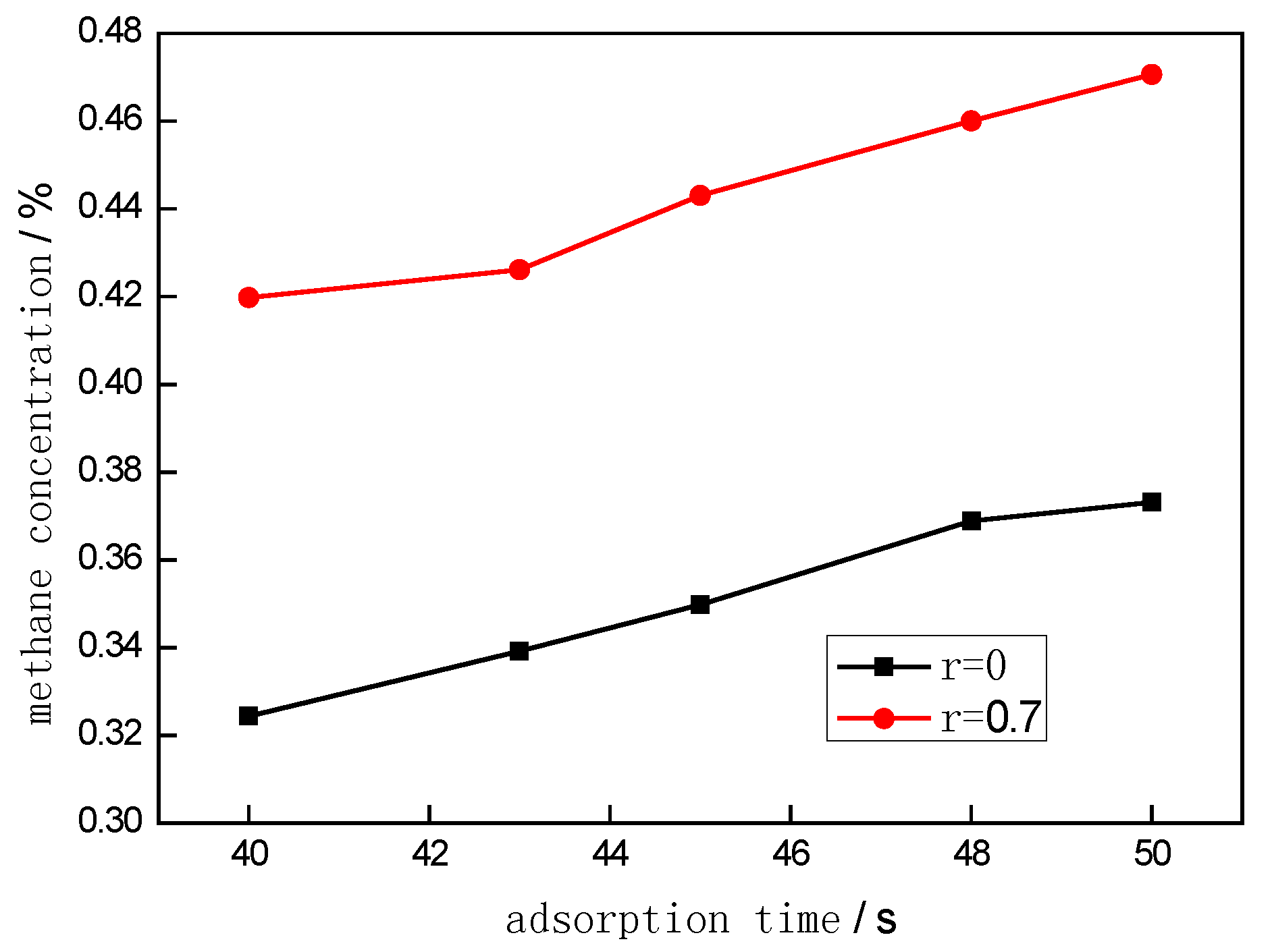
Figure 7 exhibits the variations of methane concentration in the product with adsorption time, using cycle (a) when the vacuum exhaust ratio (r) was set as 0 and 0.7, respectively. During the experiments, pressure-equalizing time was set as 2 s, adsorption pressure and desorption pressure were set as 135 kPa and 14 kPa, respectively. It can be easily observed that the addition of the vacuum exhaust step in the cycle can remarkably enhance the concentration of methane in the product.
The primary reason is described below. During the adsorption process, a portion of gas rich in nitrogen and oxygen (N2 and O2, a weak-absorbed phase component) accumulated in the dead space on the top of the adsorption bed; meanwhile, the adsorption mass-transfer zone (MTZ) was still in the upper part of the adsorption bed before the pressure equalizing switch, in which most of the gas flows into another adsorption bed in the pressure equalizing process. However, after pressure equalizing, this gas was still not completely exhausted from the adsorption bed to be desorbed, and the gas remained in the upper part of the adsorption bed. At that time, the MTZ in the adsorption bed gradually moved to the exhaust end during the vacuum exhaust process. Accordingly, gas in the adsorption bed with low methane concentration gradually flowed out from the adsorption bed, while the percentage of gas with high methane concentration increased in the adsorption bed. Bae et al. [22] also showed the same result, that the methane concentration increases with the desorption time, and the desorption gas was mostly air if the desorption time was very short desorption. On the other hand, methane’s mass transfer coefficient is lower than nitrogen and oxygen, and methane desorbed slower than nitrogen and oxygen [15,19,35]. Thus, nitrogen and oxygen desorbed first, and the vacuum exhaust step can emit this part of the low methane concentration gas. It can thus be concluded, that the vacuum exhaust can further exhaust the gas with low methane concentration and increase the concentration of methane in the adsorption bed, i.e., the addition of vacuum exhaust can increase the concentration of the product.
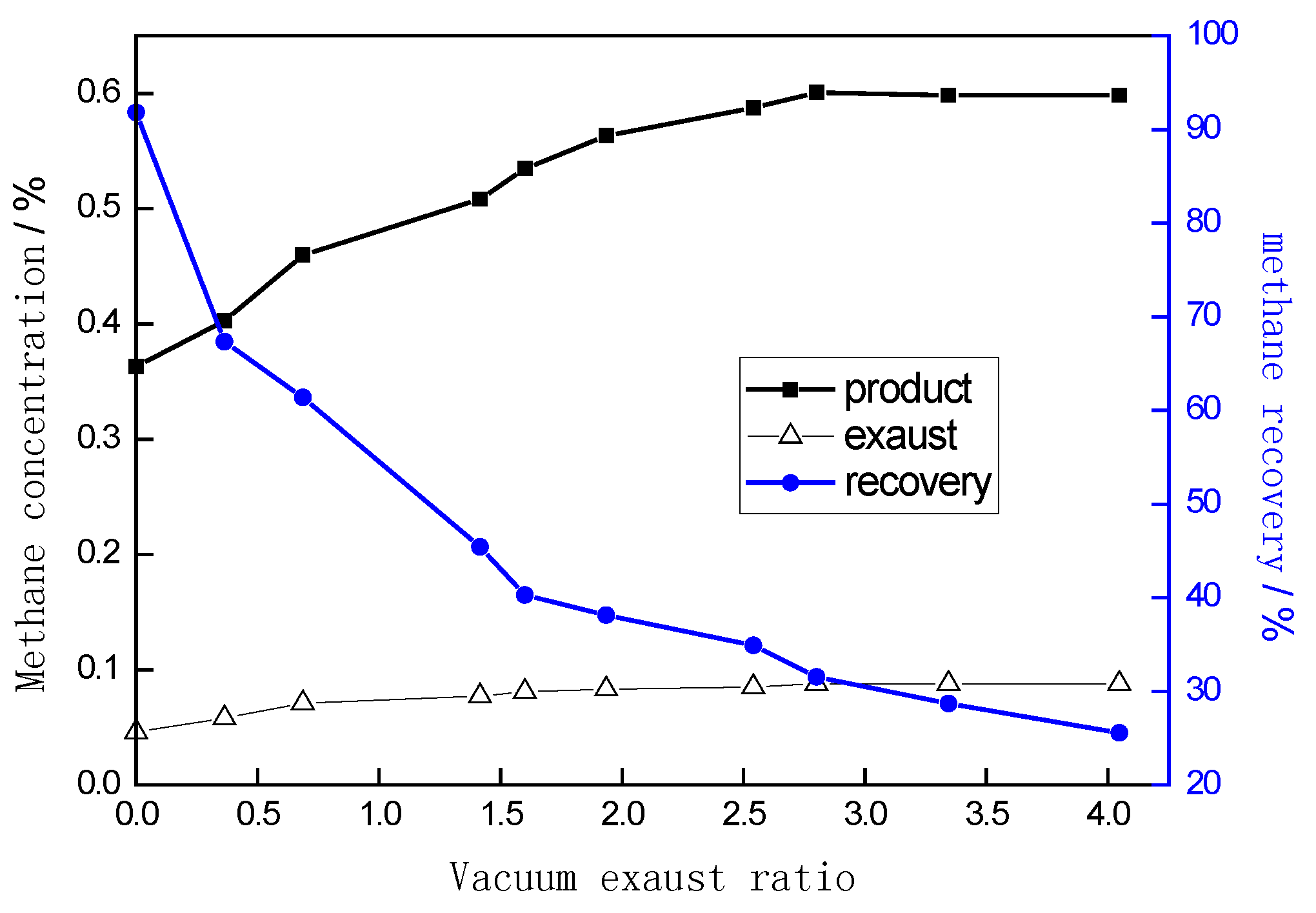
Figure 8 displays the concentrations of methane in the products and exhaust gas as well as methane recovery ratios using cycle a when r was set as different values, during which adsorption and desorption pressures were set as 135 kPa and 14 kPa, respectively. It can be observed that when r = 0 (i.e., no vacuum exhaust step was applied in this cycle), methane concentration in the product was 0.33%; as r increased to 2.8, methane concentration in the product reached a maximum of 0.546%, which was an enhancement of 65.5% compared with the condition when r = 0. Additionally, with a further increase in r, the concentration of the product tended to be stable.
As stated above, the product recovered via vacuuming was actually the gas mixture of dissociative gas in the dead space, low-concentration light-component gas in the interval of adsorbent, and the desorbed gas rich in heavy component methane. In the top of the adsorption bed, many free N2 were observed in the dead space of the adsorption bed. Meanwhile, the N2 concentration in the MTZ was relatively high in this section, and the concentration of methane that was desorbed from this portion of gas was necessarily low. After the addition of the vacuum exhaust process, this portion of gas would be exhausted; with the increase in r, the percentage of the desorbed heavy-component gas in the product increased steadily, thereby leading to the increased methane concentration in the product. As r increased to 2.8, the first two portions of gas were completely discharged, and the product was almost composed of the desorbed methane-rich gas. Therefore, further increasing r imposed a slight effect on the variation of methane concentration in the product.
It can also be observed from Figure 8 that the concentration variation of exhausted gas with r was roughly identical to that of the product, which reached the maximum when r = 2.8. After vacuum exhaust, some methane was still retained in the adsorption bed Additionally, due to the addition of the vacuum exhaust step, low-concentration gas was already pumped out, and high-concentration heavy-component gas (methane) was retained in the adsorption bed, which was brought out from the exhaust end of the adsorption bed in the next adsorption process [31]. On the other hand, since the MTZ in the adsorption bed moved to the exhaust end under the action of the vacuum exhaust, the desorbed methane concentration was enhanced, and simultaneously, the methane concentration in the effluent gas was also enhanced. However, this portion of heavy-component gas increased with the increase in r and almost reached the maximum when r = 2.8. This is also reflected in Bae’s study [25].
Meanwhile, as shown in Figure 8, the recovery ratio of methane decreased from 91.8% to 31.5% when r increased from 0 to 2.8. Unlike the variation in methane concentration, the recovery ratio of methane decreased steadily with the further increase of r; as r increased to 4.0, the recovery ratio of methane dropped to 25.6%. This is because of the addition of the vacuum exhaust step, the flow of product decreased gradually, and therefore, the recovery ratio of methane further decreased. Accordingly, it can be concluded that high-concentration methane in the product can be acquired with some loss in the recovery ratio. In practical applications, both the concentration and recovery ratio of methane should be balanced.
3.3. Effect of Reflow of Exhausted Gas in the Vacuuming Process on Separation Effect
The exhausted gas in cycle a was directly discharged to the atmosphere, which led to the decrease in the recovery ratio. With the increase of r, the methane concentration of this exhausted gas may be close to or higher than the feed gas. If the gas was directly exhausted to the atmosphere, methane may be wasted. Therefore, the exhausted gas should be recycled to the system. Cycle b is a VPSA process with the exhausted gas being recycled.
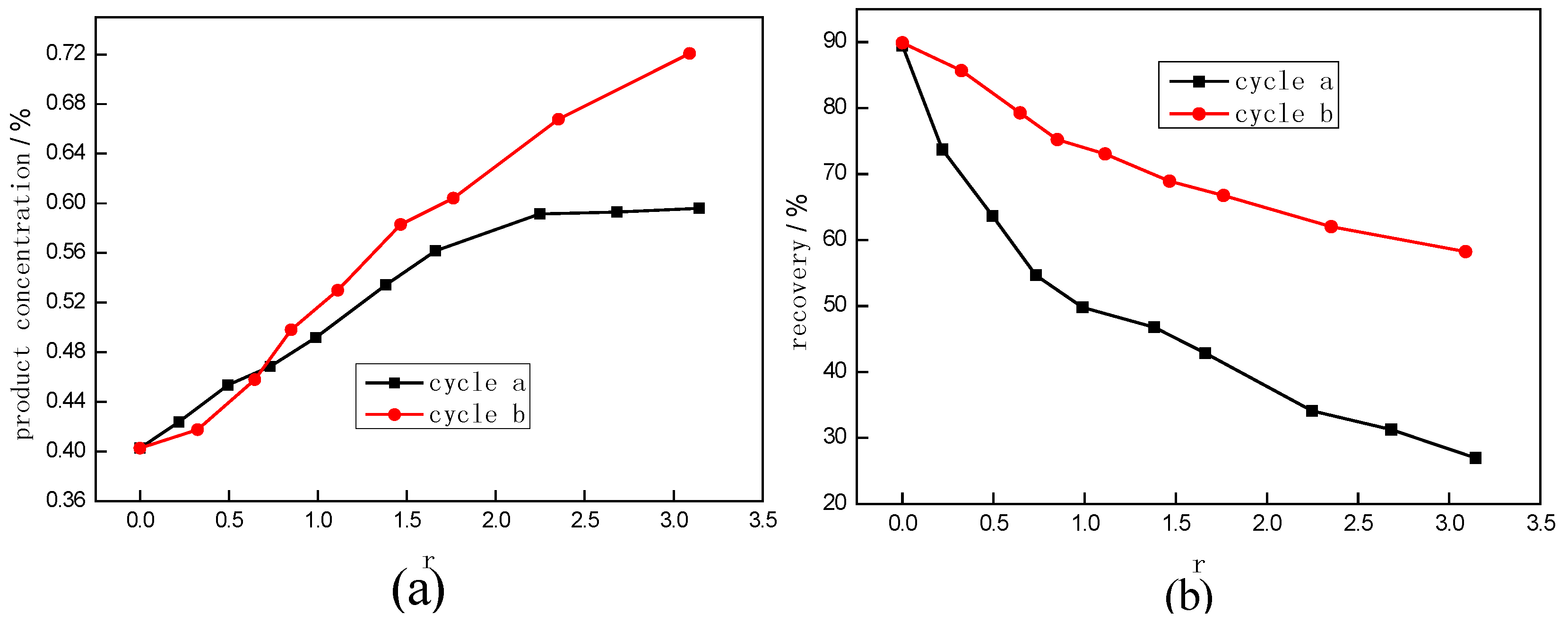
Figure 9 compares the enrichment performances of methane using cycle a and cycle b, during which adsorption time and pressure-equalizing time were set as 45 s and 4 s, and the adsorption pressure and desorption pressure were set as 140 kPa and 14 kPa, respectively. It can be observed that, using cycle b, methane concentration in the product increased from 0.4% to 0.69% as r increased from 0 to 3.1. Through comparison of the two cycles, when r < 0.7, the methane concentration using cycle b was lower; when r > 0.7, the methane concentration using cycle b was significantly higher. The primary reason for this can be described as follow. When r < 0.7, the concentration of the exhausted gas was lower than 0.2% of the feed gas, and therefore, the gas that entered the adsorption bed in the adsorption process was diluted to less than 0.2%. With the increase of r, the concentration of methane in the exhausted gas increased gradually; meanwhile, at a lower r, the desorption pressure was lower while the concentration of methane in the desorbed gas was higher. Accordingly, as r increased to a certain value, the concentration of methane in the product using cycle b was higher than that using cycle a.
Figure 9b compares the recovery ratios of methane with and without the reflow of exhausted gas. Apparently, when r was set as different values, the recovery ratios of methane after the addition of the reflow of exhausted gas (cycle a) were much higher than the values without the reflow of exhausted gas (cycle b); moreover, with the increase of r, the recovery ratio of the product also decreased gradually. It was also observed that after the addition of the reflow of exhausted gas, the recovery ratio of methane decreased from 90% to 58% as r increased from 0 (no reflow of the exhausted gas was used) to 3.1. When r = 0.7, the recovery ratio of methane was approximately 75%.
3.4. Application of Vacuum Exhaust Procedure in Pilot-Scale VAM Recovery System
A pilot-scale test system was developed for examining enrichment behaviors of ventilation air methane (VAM).
As we could not get the vacuum exhaust ratio (r) in the pilot-scale system, the dimensionless vacuum exhaust time (Tve) was employed in this study. The dimensionless vacuum exhaust time (Tve) was defined as follow.
Figure 10 shows the variation in the concentration of the product with dimensionless vacuum exhaust time (Tve), during which operating pressure remained unchanged, and the concentration of methane in the feed gas was maintained at 0.2%. It was observed that the concentration of product increased gradually with the increase in Tve. When Tve = 0 (without vacuum exhaust), the product’s concentration was only 0.45%, which then increased to 0.82% as Tve increased to 0.2. The product concentration was 1.8 times greater than the value achieved when no vacuum exhaust step was used. Additionally, with the increase in Tve, the recovery ratio decreased gradually. When Tve = 0, the concentration of methane in the product was only 0.45% and the recovery ratio of methane was approximately 91%; as Tve increased to approximately 0.2, the recovery ratio of methane decreased to only 60%.
This is mainly due to the fact that the flow rate of product decreased significantly by use of the vacuum exhaust process, while more methane was exhausted from the waste gas. Accordingly, the recovery ratio of methane decreased gradually with the increase in Tve.
The research results confirmed that the addition of the vacuum exhaust process can significantly enhance the product concentration but greatly decrease the flow of methane. Therefore, during the enrichment of VAM, the concentration of methane in the product can be enhanced by gradually increasing the value of Tve. The results show methane concentration can be enhanced by about 4 times with one stage, by use of the vacuum exhaust process in this pilot-scale system.
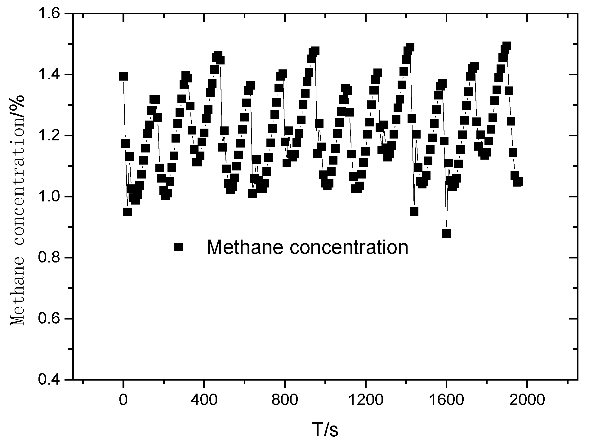
Figure 11 shows the variation in the concentration of methane in the product when the two-stage VPSA system operated stably, during which the VAM concentration was set as 0.2%. In order to ensure a more stable methane flow during the second-stage separation process, no vacuum exhaust step was set in the first stage, while Tve in the second stage lasted 0.1. It can be observed, that after two-stage adsorption separation, VAM was enriched from 0.2% to over 1%. The product concentration fluctuated within a range of 1%~1.5%, with an average concentration of 1.2%. The fluctuation in methane concentration can be attributed to great variations in methane concentration and the flow rate of the product with desorption pressure change. Further, the two-stage adsorption separation process aggravated the fluctuation in the concentration of methane in the product. For enhancing the stability of methane concentration in the product, the volume of buffer tank in the adsorption system can be increased to achieve the stability of both concentration and flow of production in a two-stage separation process.
4. Conclusions
In this paper, a coconut shell activated carbon was employed as the sorbent for VAM recovery. A new VPSA process with a vacuum exhaust step was introduced to enhance the methane concentration. Key results are summarized as follows:
- (1).
- The coconut shell activated carbon with equilibrium selectivity of 5.12 was used as the sorbent for VAM recovery. A vacuum exhaust step introduced into the three-bed vacuum pressure swing adsorption (VPSA) process enhanced the methane product purity by 2–3.45 times without changing adsorption and desorption pressure. The concentration of methane in the product increased (from 0.4% to 0.69%) with an increase in the vacuum exhaust ratio (from 0 to 3.1), when the feed gas was 0.2%.
- (2).
- A critical vacuum exhaust ratio may exist and was determined to be 0.7 for this work, below which the product purity was lower in cycle b than in cycle a, and above which, the product purity was enhanced.
- (3).
- A pilot-scale system for VAM enrichment was built and gave results that correlated well with the laboratory results regarding the effects of the vacuum exhaust on gas separation. Practically, VAM with a flow rate of 500 m3/h and concentration of 0.2% can be enriched to more than 1.2%. This could be a reference for VAM utilization by lean-burn combustion turbines technologies.
Author Contributions
Xiong Yang and Yingshu Liu conceived of the main idea and wrote the manuscript. Ziyi Li, Chuanzhao Zhang and Yi Xing contributed to the experimental work and analyzed the data.
Acknowledgments
The authors express their gratitude to the National Natural Science Foundation of China (51604016), The National High-tech Development Plan Project (No. 2009AA063201) and Fundamental Research Funds for the Central Universities (FRF-BD-16-009A).
Conflicts of Interest
The authors declare no conflict of interest.
References
- Tutak, M. Analysis of varying levels of methane emissions from coal mines in Poland. In Proceedings of the SGEM 2017 Vienna GREEN Conference, Vienna, Austria, 27–29 November 2017; Volume 17, pp. 301–308. [Google Scholar]
- Isaksen, I.S.A.; Berntsen, T.K.; Dalsøren, S.B.; Eleftheratos, K.; Orsolini, Y.; Rognerud, B.; Stordal, F.; Søvde, O.A.; Zerefos, C.; Holmes, C.D. Atmospheric ozone and methane in a changing climate. Atmosphere 2014, 5, 518–535. [Google Scholar] [CrossRef] [Green Version]
- Brodny, J.; Tutak, M. Analysis of methane emission into the atmosphere as a result of mining activity. In Proceedings of the SGEM 2016 International Multidisciplinary Scientific Geo Conference: SGEM: Surveying Geology & mining Ecology Management, Sofia, Bulgaria, 28 June–7 July 2016; pp. 83–90. [Google Scholar]
- Su, S.; Agnew, J. Catalytic combustion of coal mine ventilation air methane. Fuel 2006, 85, 1201–1210. [Google Scholar] [CrossRef]
- US EPA. Assessment of the Worldwide Market Potential for Oxidising Coal Mine Ventilation Air Methane; EPA 430-R-03-002; United States Environmental Protection Agency: Washington, DC, USA, 2003. [Google Scholar]
- Cheng, Y.P.; Wang, L.; Zhang, X.L. Environmental impact of coal mine methane emissions and responding strategies in China. Int. J. Greenh. Gas Control 2011, 5, 157–166. [Google Scholar] [CrossRef]
- Kosmack, D. Capture and Use of Coal Mine Ventilation Air Methane; CONSOL Energy Inc. Research & Development: Pittsburgh, PA, USA, 2003. [Google Scholar]
- Kosmack, D.A.; Winschel, R.A.; Zak, K.P.; First, U.S. field trial of oxidation technology for ventilation air methane. In Proceedings of the 1st Annual US Coal Mine Methane Conference, St. Louis, MI, USA, 25–27 September 2007. [Google Scholar]
- Mattus, R. Full Operation—The World’s First VAM Power Plant; MEGTEC Systems Inc.: De Pere, WI, USA, 2008. [Google Scholar]
- Gosiewski, K.; Warmuzinski, K. Effect of the mode of heat withdrawal on the asymmetry of temperature profiles in reverse-flow reactors. Catalytic combustion of methane as a test case. Chem. Eng. Sci. 2007, 62, 2679–2689. [Google Scholar] [CrossRef]
- Warmuzinski, K. Harnessing methane emissions from coal mining. Process Saf. Environ. Prot. 2008, 86, 315–320. [Google Scholar] [CrossRef]
- Su, S.; Yu, X. A 25 kWe low concentration methane catalytic combustion gas turbine prototype unit. Energy 2015, 79, 428–438. [Google Scholar] [CrossRef]
- Su, S.; Beath, A.; Guo, H.; Mallett, C. An assessment of mine methane mitigation and utilization technologies. Prog. Energy Combust. Sci. 2005, 31, 123–170. [Google Scholar] [CrossRef]
- Baris, K. Assessing ventilation air methane (VAM) mitigation and utilization opportunities: A case study at Kozlu Mine, Turkey. Energy Sustain. Dev. 2013, 17, 13–23. [Google Scholar] [CrossRef]
- Olajossy, A.; Gawdzik, A.; Budner, Z.; Dula, J. Methane separation from coal mine methane gas by vacuum pressure swing adsorption. Chem. Eng. Res. Des. 2003, 81, 474–482. [Google Scholar] [CrossRef]
- Olajossy, A. Effective recovery of methane from coal mine methane gas by vacuum pressure swing adsorption: A pilot scale case study. Chem. Eng. Sci. 2013, 1, 46–54. [Google Scholar] [CrossRef]
- Yang, X.; Liu, Y.; Li, Y.; Meng, Y.; Zhang, C.; Yan, J. Safe separation of the low-concentration and oxygen-bearing coal mine methane by vacuum pressure swing adsorption. Adsorpt. Sci. Technol. 2014, 32, 667–679. [Google Scholar] [CrossRef]
- Yang, H.; Yin, C.; Jiang, B.; Zhang, D. Optimization and analysis of a VPSA process for N2/CH4 separation. Sep. Purif. Technol. 2014, 134, 232–240. [Google Scholar] [CrossRef]
- Zhou, Y.; Fu, Q.; Shen, Y.; Sun, W.; Zhang, D.; Li, D.; Yan, H. Upgrade of low-concentration oxygen-bearing coal bed methane by a vacuum pressure swing adsorption process: Performance study and safety analysis. Energy Fuels 2016, 30, 1496–1509. [Google Scholar] [CrossRef]
- Gomes, V.G.; Hassan, M.M. Coalseam methane recovery by vacuum swing adsorption. Sep. Purif. Technol. 2001, 24, 189–196. [Google Scholar] [CrossRef]
- Jayaraman, A.; Hernandez-Maldonado, A.J.; Yang, R.T.; Chinn, D.; Munson, C.L.; Mohr, D.H. Clinoptilolites for nitrogen/methane separation. Chem. Eng. Sci. 2004, 59, 2407–2417. [Google Scholar] [CrossRef]
- Delgado, J.A.; Uguina, M.A.; Sotelo, J.L.; Ruíz, B. Modelling of the fixed-bed adsorption of methane/nitrogen mixtures on silicalite pellets. Sep. Purif. Technol. 2006, 50, 192–203. [Google Scholar] [CrossRef]
- Grande, C.A.; Cavenati, S.; Da Silva, F.A.; Rodrigues, A.E. Carbon molecular sieves for hydrocarbon separations by adsorption. Ind. Eng. Chem. Res. 2005, 44, 7218–7227. [Google Scholar] [CrossRef]
- Thiruvenkatachari, R.; Su, S.; Yu, X.X. Carbon fibre composite for ventilation air methane (VAM) capture. J. Hazard. Mater. 2009, 172, 1505–1511. [Google Scholar] [CrossRef] [PubMed]
- Bae, J.S.; Su, S.; Yu, X.X. Enrichment of ventilation air methane (VAM) with carbon fiber composites. Environ. Sci. Technol. 2014, 48, 6043–6049. [Google Scholar] [CrossRef] [PubMed]
- Ouyang, S.; Xu, S.; Song, N.; Jiao, S. Coconut shell-based carbon adsorbents for ventilation air methane enrichment. Fuel 2013, 113, 420–425. [Google Scholar] [CrossRef]
- Li, Z.; Liu, Y.; Zhang, C.; Yang, X.; Ren, J.; Jiang, L. Methane recovery from coal bed gas using modified activated carbons: A combined method for assessing the role of functional groups. Energy Fuels 2015, 29, 6858–6865. [Google Scholar] [CrossRef]
- Liu, Y.; Yang, X.; Li, Y.; Yang, H.; Zhang, C.; Meng, Y. The experiment study on ventilation air methane enrichment by vacuum pressure swing adsorption. Energy Educ. Sci. Technol. Part A-Energy Sci. Res. 2012, 29, 217–226. [Google Scholar]
- Li, Z.; Liu, Y.; Yang, X.; Xing, Y.; Wang, Z.; Yang, Q.; Yang, R.T. Desorption kinetics of naphthalene and acenaphthene over two activated carbons via thermogravimetric analysis. Energy Fuels 2015, 29, 5303–5310. [Google Scholar] [CrossRef]
- Thommes, M.; Kaneko, K.; Neimark, A.V.; Olivier, J.P.; Rodriguez-Reinoso, F.; Rouquerol, J.; Sing, K.S. Physisorption of gases, with special reference to the evaluation of surface area and pore size distribution (IUPAC Technical Report). Pure Appl. Chem. 2015, 87, 1051–1069. [Google Scholar] [CrossRef]
- Kikkinides, E.S.; Yang, R.T. Response to Comments on Concentration and Recovery of CO2 from Flue-Gas by Pressure Swing Adsorption. Ind. Eng. Chem. Res. 1994, 33, 2881. [Google Scholar] [CrossRef]
- Zhang, J.; Webley, P.A.; Xiao, P. Effect of process parameters on power requirements of vacuum swing adsorption technology for CO2 capture from flue gas. Energy Conver. Manag. 2008, 49, 346–356. [Google Scholar] [CrossRef]
- Ruthven, D.M.; Farooq, S.; Knaebel, K.S. Pressure Swing Adsorption; VCH Publishers Inc.: New York, NY, USA, 1994. [Google Scholar]
- Yang, R.T. Adsorbents: Fundamentals and Applications; John Wiley & Sons, Inc.: Hoboken, NJ, USA, 2003. [Google Scholar]
- Sircar, S.; Kumar, R. Column dynamics for adsorption of bulk binary gas mixtures on activated carbon. Sep. Sci. Technol. 1986, 21, 919–939. [Google Scholar] [CrossRef]
Figure 1.
Schematic diagram of adsorption separation experimental unit. 1—blower; 2—gas buffer; 3—mass flow controller; 4—solenoid valve; 5—adsorption bed; 6—throttle valve; 7—check valve; 8—back pressure valve; 9—methane analyzer; 10—vacuum pump; PI—pressure transfer.
Figure 1.
Schematic diagram of adsorption separation experimental unit. 1—blower; 2—gas buffer; 3—mass flow controller; 4—solenoid valve; 5—adsorption bed; 6—throttle valve; 7—check valve; 8—back pressure valve; 9—methane analyzer; 10—vacuum pump; PI—pressure transfer.
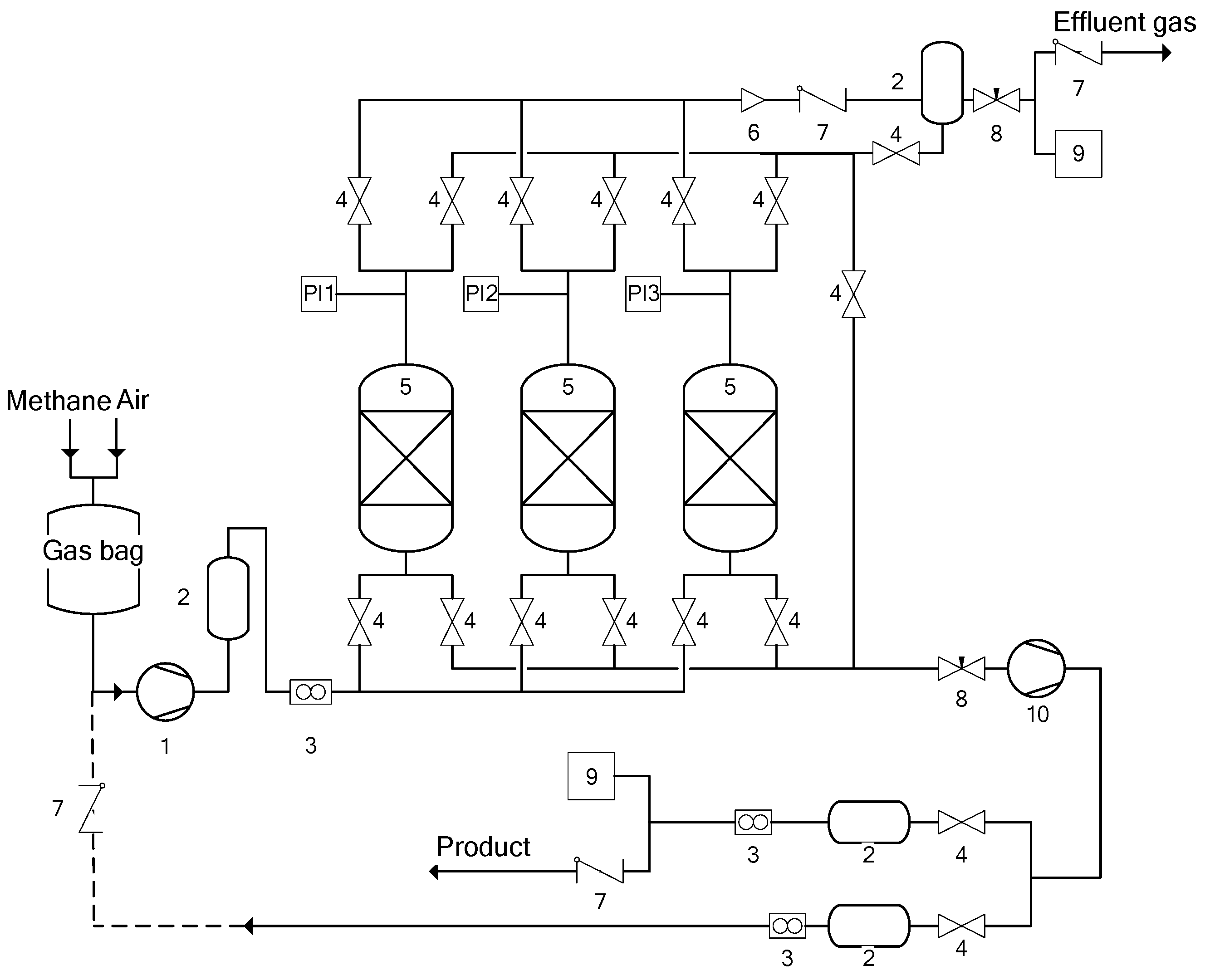
Figure 2.
Gas flow switching sequence.
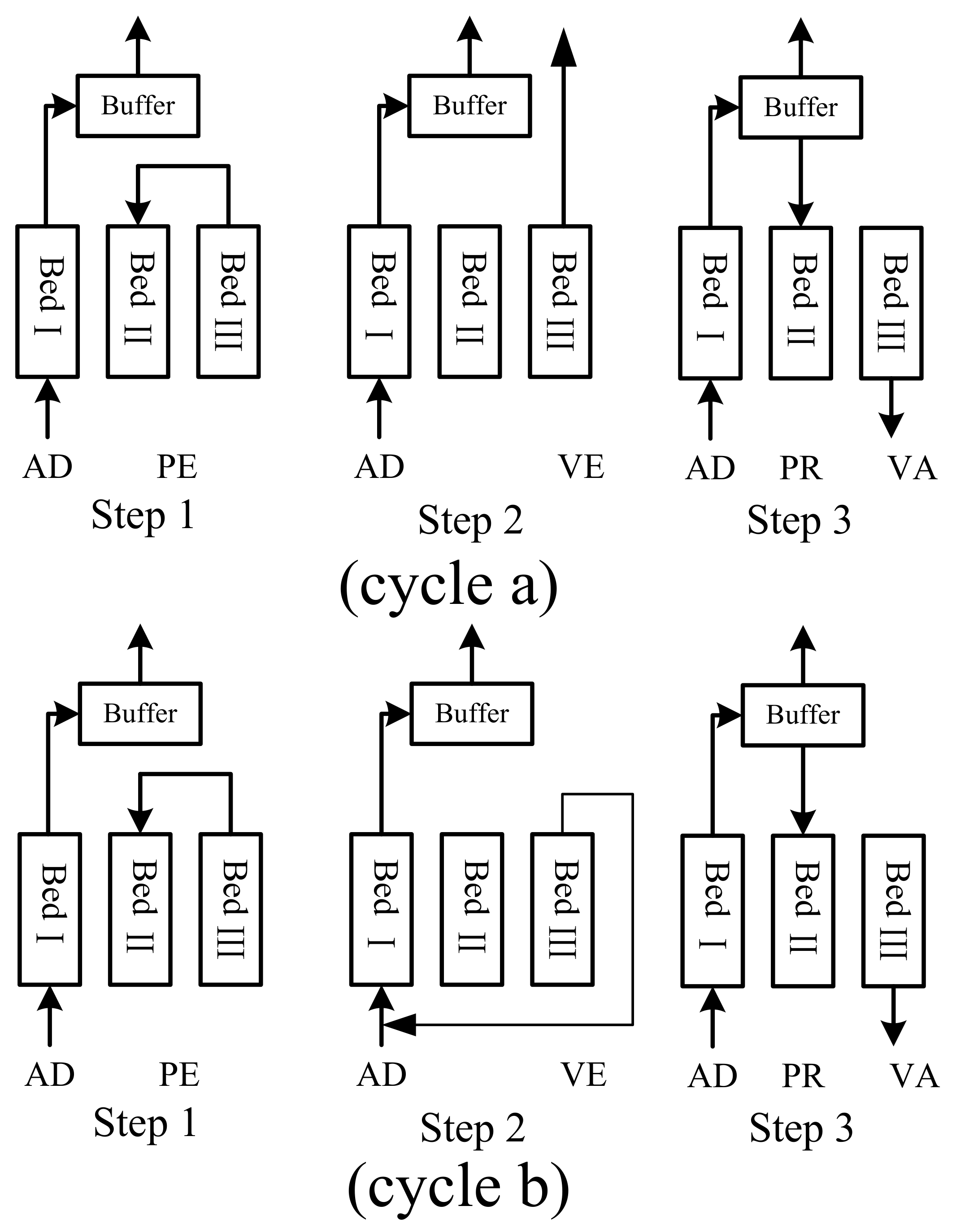
Figure 3.
Process diagram for the pilot plant. BED-adsorber; PT-pressure transmitter; TT-temperature transmitter; V-gas buffer; KV-pneumatic valve; FT-flowmeter; MV-gas-manual control valve; P1/P2-pump; VP1/VP2-vacuum pump; Ⓐ- methane sensor.
Figure 3.
Process diagram for the pilot plant. BED-adsorber; PT-pressure transmitter; TT-temperature transmitter; V-gas buffer; KV-pneumatic valve; FT-flowmeter; MV-gas-manual control valve; P1/P2-pump; VP1/VP2-vacuum pump; Ⓐ- methane sensor.

Figure 4.
Pilot plant photo.
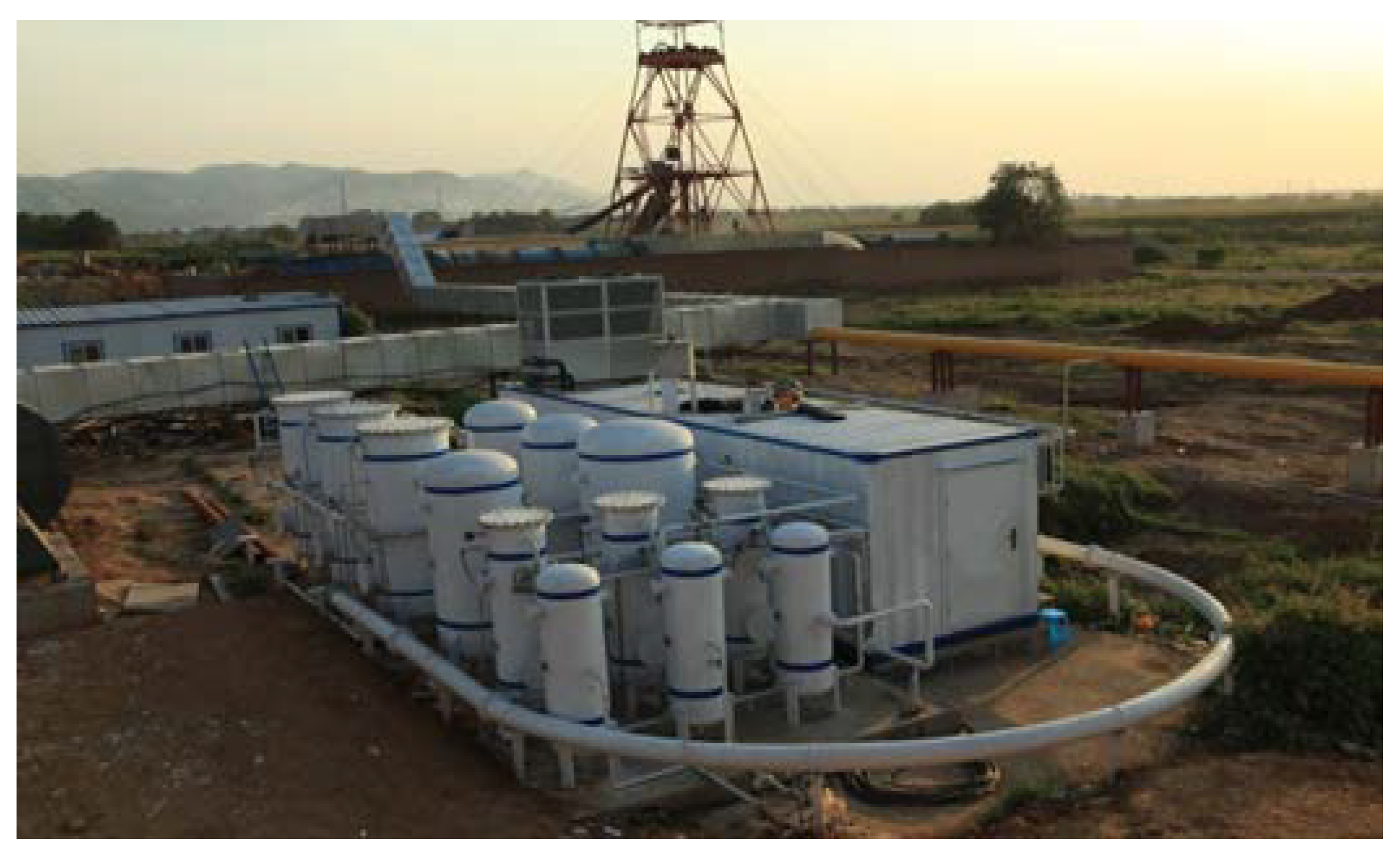
Figure 5.
Adsorption isotherms for CH4 and N2.

Figure 6.
Pore size distribution of AC.

Figure 7.
Comparison of the product methane concentration with and without the vacuum exhaust process.
Figure 7.
Comparison of the product methane concentration with and without the vacuum exhaust process.

Figure 8.
Effect of different vacuum exhaust ratio on methane concentration and recovery.

Figure 9.
Comparison of the enrichment performances by using cycle a and cycle b. (a) Effect of different vacuum exhaust ratio on methane concentration with and without the vacuum exhaust gas recovery process; (b) Effect of different vacuum exhaust ratio on methane recovery with and without the vacuum exhaust gas recovery process.

Figure 10.
Effect of vacuum exhaust ratio on methane concentration.
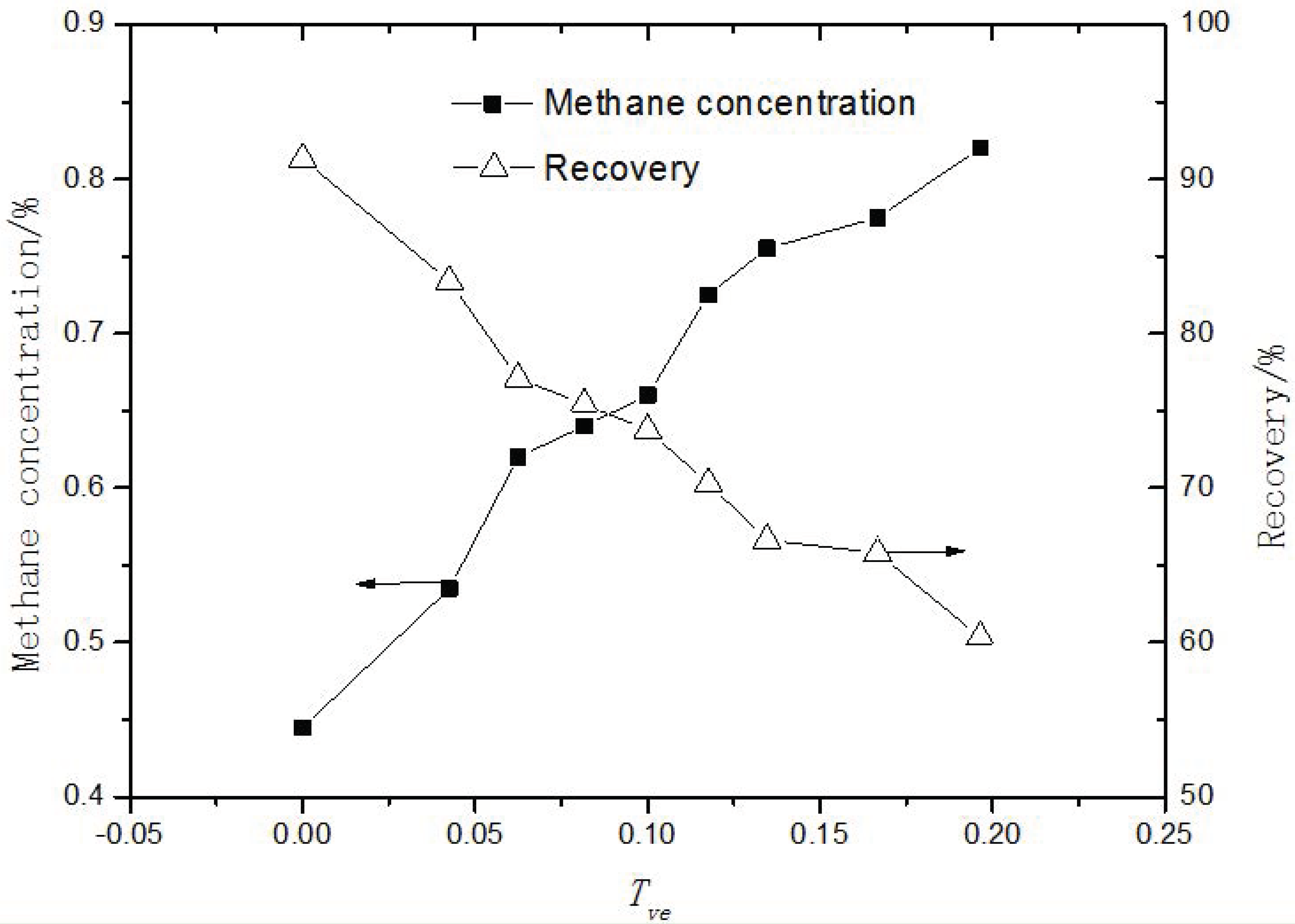
Figure 11.
Influence of cycle time on product gas concentration.


Table 1.
Switching sequence.
| Bed A | AD | PE↓ | VE | VA | PE↑ | PR | |||
| Bed B | PE↑ | PR | AD | PE↓ | VE | VA | |||
| Bed C | PE↓ | VE | VA | PE↑ | PR | AD | |||
Table 2.
Langmuir adsorption isotherm constants.
| Sorbate | 298 K | 308 K | 318 K | |||
|---|---|---|---|---|---|---|
| qm (mmol/g) | b (mmhg−1) | qm (mmol/g) | b (mmhg−1) | qm (mmol/g) | b (mmhg−1) | |
| CH4 | 1.99 | 0.001 | 1.916 | 9.342 × 10⁻⁴ | 1.824 | 7.894 × 10⁻⁴ |
| N2 | 1.697 | 2.746 × 10⁻⁴ | 1.709 | 2.328 × 10⁻⁴ | 1.975 | 1.635 × 10⁻⁴ |
Table 3.
Adsorbent parameters.
| Adsorbent | BET Surface/(m2/g) | Pore Volume/(cc/g) |
|---|---|---|
| AC | 1155 | 0.67 |
© 2018 by the authors. Licensee MDPI, Basel, Switzerland. This article is an open access article distributed under the terms and conditions of the Creative Commons Attribution (CC BY) license (http://creativecommons.org/licenses/by/4.0/).
Share and Cite
MDPI and ACS Style
Yang, X.; Liu, Y.; Li, Z.; Zhang, C.; Xing, Y. Vacuum Exhaust Process in Pilot-Scale Vacuum Pressure Swing Adsorption for Coal Mine Ventilation Air Methane Enrichment. Energies 2018, 11, 1030. https://doi.org/10.3390/en11051030
AMA Style
Yang X, Liu Y, Li Z, Zhang C, Xing Y. Vacuum Exhaust Process in Pilot-Scale Vacuum Pressure Swing Adsorption for Coal Mine Ventilation Air Methane Enrichment. Energies. 2018; 11(5):1030. https://doi.org/10.3390/en11051030
Chicago/Turabian StyleYang, Xiong, Yingshu Liu, Ziyi Li, Chuanzhao Zhang, and Yi Xing. 2018. "Vacuum Exhaust Process in Pilot-Scale Vacuum Pressure Swing Adsorption for Coal Mine Ventilation Air Methane Enrichment" Energies 11, no. 5: 1030. https://doi.org/10.3390/en11051030
Note that from the first issue of 2016, this journal uses article numbers instead of page numbers. See further details here.