Rectifier Current Control for an LLC Resonant Converter Based on a Simplified Linearized Model


1
School of Electrical Engineering, Wuhan University, Wuhan 430072, China
2
State Key Laboratory of Advanced Electromagnetic Engineering and Technology, School of Electrical and Electronic Engineering, Huazhong University of Science and Technology, Wuhan 430074, China
3
China Electric Power Research Institute, Wuhan 430074, China
4
School of Electrical and Electronic Engineering, Hubei Polytechnic University, Huangshi 435003, China
*
Author to whom correspondence should be addressed.
Energies 2018, 11(3), 579; https://doi.org/10.3390/en11030579
Submission received: 11 January 2018
/
Revised: 1 February 2018
/
Accepted: 6 February 2018
/
Published: 7 March 2018
Abstract
:In this paper, a rectifier current control for an LLC resonant converter is proposed, based on a simplified, two-order, linearized model that adds a rectifier current feedback inner loop to improve dynamic performance. Compared to the traditional large-signal model with seven resonant states, this paper utilizes a rectifier current state to represent the characteristics of the resonant states, simplifying the LLC resonant model from seven orders to two orders. Then, the rectifier current feedback inner loop is proposed to increase the control system damping, improving dynamic performance. The modeling and design methodology for the LLC resonant converter are also presented in this paper. A frequency analysis is conducted to verify the accuracy of the simplified model. Finally, a 200 W LLC resonant converter prototype is built to verify the effectiveness of the proposed control strategy. Compared to a traditional single-loop controller, the settling time and voltage droop were reduced from 10.8 ms to 8.6 ms and from 6.8 V to 4.8 V, respectively, using the proposed control strategy.
1. Introduction
Nowadays, more and more equipment has its energy supplied by DC sources, including integrated circuits (ICs), computers, cell phones, communications and so on [1,2,3,4]. An isolated DC/DC converter is the key component in these applications to convert the high DC voltage to low voltage, and it should have high efficiency and power density to meet the demanding requirements in terms of heat design and volume. Meanwhile, for some special applications, high, steady and dynamical performance is also required, as in the case of an IC power supply, which should maintain uninterrupted voltage to ensure data security and thus requires high dynamical performance [5], or battery charging which should ensure the control accuracy since the overvoltage or overcurrent could damage the batteries [6,7,8]. Therefore, high efficiency, high power density and high performance are the main goals when developing a DC/DC converter.
LLC resonant converters have been widely used among the various DC converters due to their outstanding advantages, like zero voltage switching (ZVS) for the primary Mosfets and zero current switching (ZCS) for the secondary diodes, which help them reach high efficiency and power density [9,10,11]. Generally, switching frequency modulation methods are used in LLC resonant converters to regulate the output voltage and current, but the nonlinear characteristics make it difficult for conventional linear control strategies to achieve the expected performance. Although increasing efforts have been made in control research on the LLC resonant converter over the years, designing the control strategies to achieve high performance is still a research topic for the LLC resonant converter.
The gain of the LLC resonant converter rises as the frequency rises in low frequency range, while rising as the frequency falls in the high frequency range. Generally, the frequencies are usually limited to the high-frequency range to achieve ZVS. Then, a linear proportional-integral (PI) controller is used to control the converter [12], which would reduce the frequency when the output voltage is high while decreasing the frequency to increase the voltage. In [13,14,15], the proportional integral differentiation (PID) controller is proposed, which uses added differentiation parts to improve the dynamic response but also makes the converter more unstable. Three-order controllers [16,17] and current loops [18,19] are used to improve the system damping. However, the resonant current is difficult to sample, hindering the controller’s performance. Reference [20] designs a state observer to control the LLC resonant converter. Due to the nonlinear characteristics of the LLC resonant converter, no accurate model or transfer function is provided in these control strategies, which are based on the trial and error method or simulation results, making it difficult for them to guide the controller design.
Some nonlinear control schemes are proposed in other papers, such as sliding-mode control [21], bang-bang control [22], robust control [23], and self-adaptive fuzzy control [24]. These intelligent algorithms are too complex to be realized. Some papers combine linear and nonlinear control algorithms to improve the converter’s performance. In [25], the authors use an inverse function to eliminate the nonlinear characters and then design a PI controller to achieve high performance. References [26,27,28] propose an optimal trajectory control scheme. During the steady state period, the PI controller is used to achieve excellent steady performance while the optimal trajectory control is applied during the dynamic state period to improve the transfer performance from one state to another. High performance is achieved in both at the steady and dynamic state while the large and complex calculations make the control strategy hard to be realized.
Due to the lack of an accurate, simple and linear model, LLC resonant converter controller design is very difficult. The state averaging model has been widely used in pulse width modulation (PWM) converter, which uses the state average values to eliminate nonlinear characteristics [29]. However, in an LLC resonant converter, the output voltage is controlled by regulating the switching frequency, making this model method ineffective. The simulation model method is proposed in [30,31]. The amplitude frequency response of an LLC resonant converter is achieved by measuring the output voltage characteristics in the simulation model. Then, a linear transfer function is constructed to fit the amplitude-frequency response curve to describe the converter characteristics. However, this model method only builds a numerical model of the LLC resonant converter, which makes it difficult to determine the influence of the resonant parameters and operation for the purposes of the controller design. A nonlinear state model for the LLC resonant converter is built in [32] based on the extended description function (EDF) method, producing the small signal model. However, this method only considers the fundamental components’ lack of accuracy. The 3rd and 5th harmonics are considered in [33]. These models are too complex, though, and dependent on the operation conditions. When the operation conditions change, the model must be modified.
In this paper, a simplified, two-order, linearized model is presented to solve these issues by using the rectifier current to represent the resonant characteristics, reducing the model orders from seven to two. A frequency analysis of the new model is also carried out to verify its accuracy. Then, a double-loop control with rectifier current feedback for the LLC resonant converter is proposed to improve the dynamic performance by increasing the system damping. The pole placement method is discussed in terms of controller design and the experiments are presented. This paper is organized as follows. In Section 2, a nonlinear model of the LLC resonant converter is designed using the EDF method. Then, the complex nonlinear model is simplified to a two-order equal model in Section 3. In Section 4, the double-loop control strategy is presented with an inner rectifier current controller and an outer voltage controller. The simulation and experimental results are shown in Section 5 to verify the effectiveness of the proposed control strategy. Conclusions are finally presented in Section 6.
2. Modeling of LLC Resonant Converter Based on EDF
2.1. Topology Description
The topology of the LLC resonant converter is shown in Figure 1 and is similar to the series or parallel resonant converter. The input DC voltage source is connected to a full bridge converter, which connects to the resonant tank, including a series resonant inductor Lr and capacitor Cr. The magnetic inductor Lm is in parallel with the transformer’s primary side and the rectifier diodes are connected to the secondary side. The output capacitor C is large enough to be regarded as a constant voltage source. The transformer’s turns ratio is n:1:1. The resonant frequency is defined as:
2.2. Operation Principle
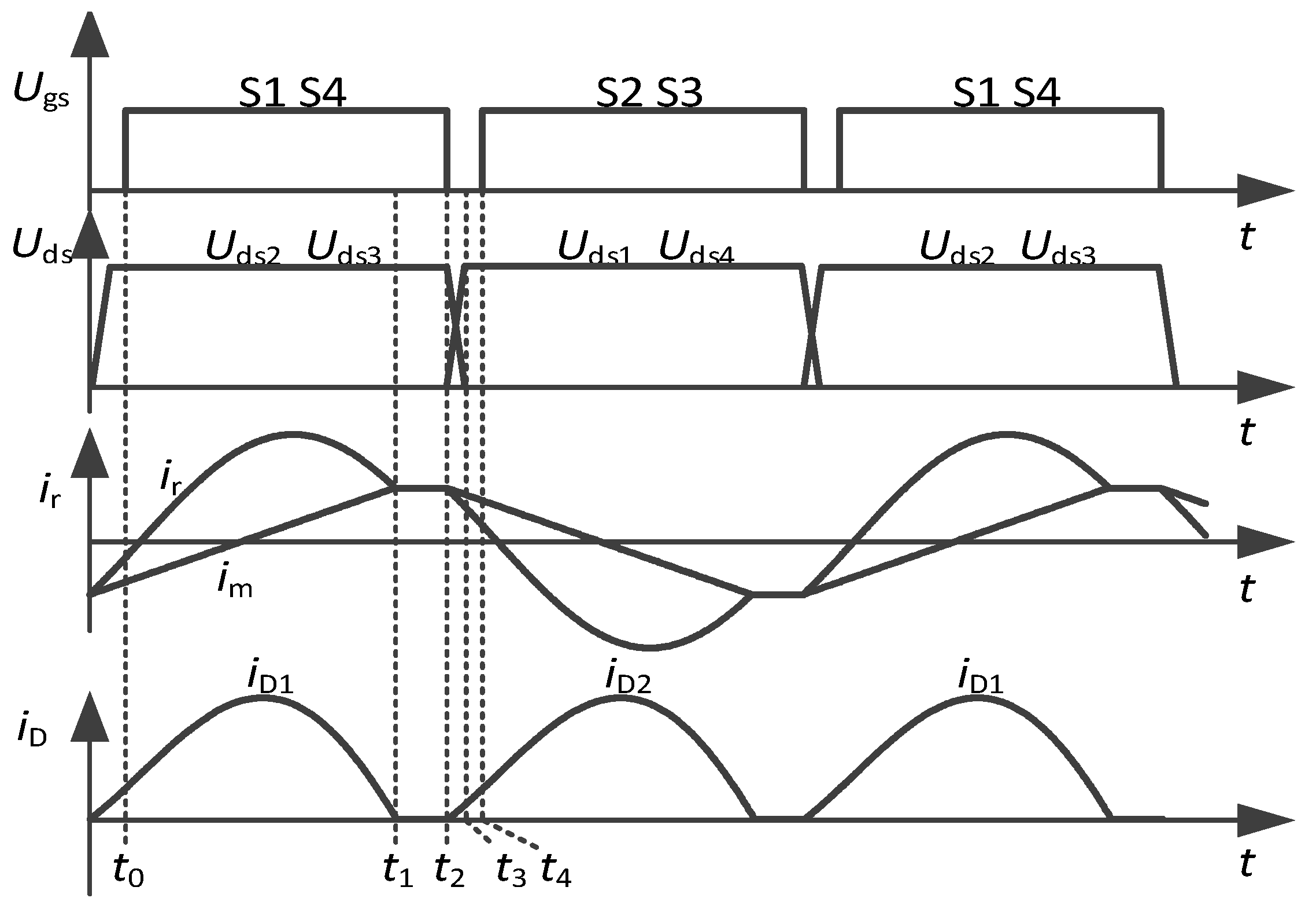
The typical operation waveforms of the LLC resonant converter are shown in Figure 2. Switchers S1, S2, S3, S4 are operated with a fixed duty cycle of 0.5 ignoring the dead time. Switchers S1 and S4, S2 and S3 are respectively turned on and off synchronously, while the operation of switchers S1 and S2, S3 and S4 are complementary.
At t0, switchers S1 and S4 turn on, the terminal voltage of resonant tank vab is vi, and then the resonant current ir rises, which is higher than the linearly rising magnetic current im, turning on the rectifier diode D1 and clamping the transformer voltage to the output voltage vo. At t1, the resonant current is equal to the magnetic current, turning off the rectifier diode D1 with zero current realizing ZCS. Then, the large output capacitors provide energy for the loads while the resonant capacitor, resonant inductor and magnetic inductor self-resonate, leading to nearly constant resonant currents due to the large magnetic inductors. At t2, switchers S1 and S4 turn off with zero voltage and resonant current ir charges the junction capacitors of S1 and S4. The drain-source voltage Uds1 and Uds4 of switchers S1 and S4 rise quickly reaching vi at t3. Then the terminal voltage vab is clamped by the input voltage vi and the resonant currents flow through the anti-parallel diodes of S2 and S3 resulting in the zero voltage of the switchers. Thus the switchers S2 and S3 can realize ZVS at t4. During the second half switching period, the operation waveforms are similar to the first one.
2.3. Modeling Based on EDF
The characteristics of the LLC resonant converter are nonlinear. In order to simplify the model, some assumptions are made based on the circuit performance:
(a) All the switchers are ideal, ignoring the influence of the inner resisters and the dead time.
(b) All the resonant variables can be regarded as sinewaves, ignoring the harmonics since the switching frequency is near the resonant frequency, resulting in small harmonics.
(c) All the resonant state variables can reach a steady state during each control period since the control frequency is far lower than the switching frequency. Then, the dynamic response of each resonant variable can be ignored during the switching period.
From assumption (a), the inverter bridge of the LLC resonant converter can be equal to a square wave voltage source and all the inner resistors are ignored. Then the LLC resonant converter can be equivalent to the circuit as shown in Figure 3. The state equations can be derived based on the circuit theory as follows.
ir, im and vcr are respectively the resonant current, magnetic current and resonant voltage. vab, vm, iBr, vo and io are respectively the input terminal voltage, magnetic voltage, rectifier current, output voltage and load current. Based on the assumption (b) and (c), the resonant variables can be regarded as sine and cosine waves as follows.
irs and irc are respectively the amplitude values of the resonant current’s sine and cosine components. ims and imc are the amplitude values of the magnetic current’s sine and cosine components. vcrs and vcrc are the amplitude values of the resonant voltage’s sine and cosine components. Similarly, only the fundamental components of vm and vab can considered in this analysis, which are derived as follows:
ip is the amplitude value of the difference current between the resonant and magnetic current.
Due to the large output capacitor, the harmonics of the rectifier current iBr can be absorbed, which can be written as follows:
Combining Equations (2)–(5), the sine and cosine components can be eliminated based on the harmonics balance. Thus the state equations of the amplitude values of the sine and cosine components can be derived as seen in Equation (7).
At the rectifier side, the rectifier currents charge the output capacitor and loads. The state equations can be expressed as shown in Equation (8).
The model of an LLC resonant converter is built to describe the converter’s characteristics. However, it is still a nonlinear system unable to achieve the transfer function between the switching frequency and the output voltage, making controller design very difficult.
3. Simplified Linear Model
The model of the LLC resonant converter is a seven-order nonlinear system in Section 2, which is too complex to guide controller design and analysis. A simplified two-order model is discussed in this section. In the Equation (5), ip is the currents connecting the resonant tank and rectifier circuit containing the information of all the resonant variables, which can be written as follows.
From Equation (7), we can obtain the follow equations.
Combine Equations (9) and (10) and the state equation of the current ip can be achieved.
The last part of the equation can be regarded as a voltage source.
vn is defined as the controlled voltage source, which is expressed as follows:
The state equation of the LLC resonant converter can be rewritten as follows:
The seven-order model shown in Equations (7) and (8) are simplified into a two-order model shown in Equation (14) by using the rectifier currents iBr. In this simplified model, the full bridge converter, resonant tank and rectifier diodes of the LLC resonant converter are regarded as a switching frequency controlled voltage source vn connected with a LC filter formed by equal inductor Ls and output capacitor C. Based on assumption (c), the resonant variables have reached the steady state during each control period achieving a steady state controlled voltage source vn which can be written as follows:
where , , , . However the transfer function between controlled voltage vn and frequency f is still nonlinear which can be approximated as a parabola wave. In order to solve the issues, the Taylor series are used to linearize the controlled voltage source which is derived as follows:
Then the linear simplified model can be achieved.
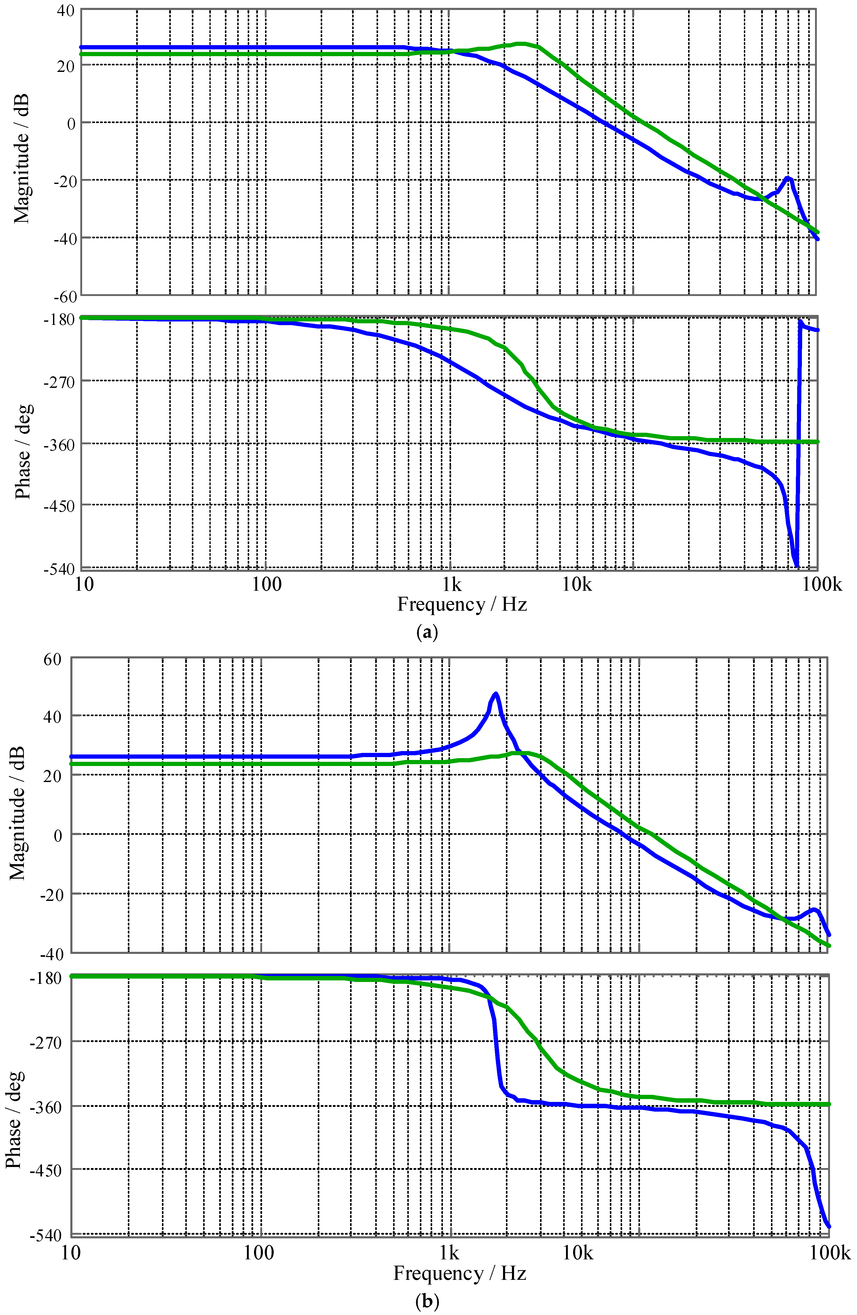
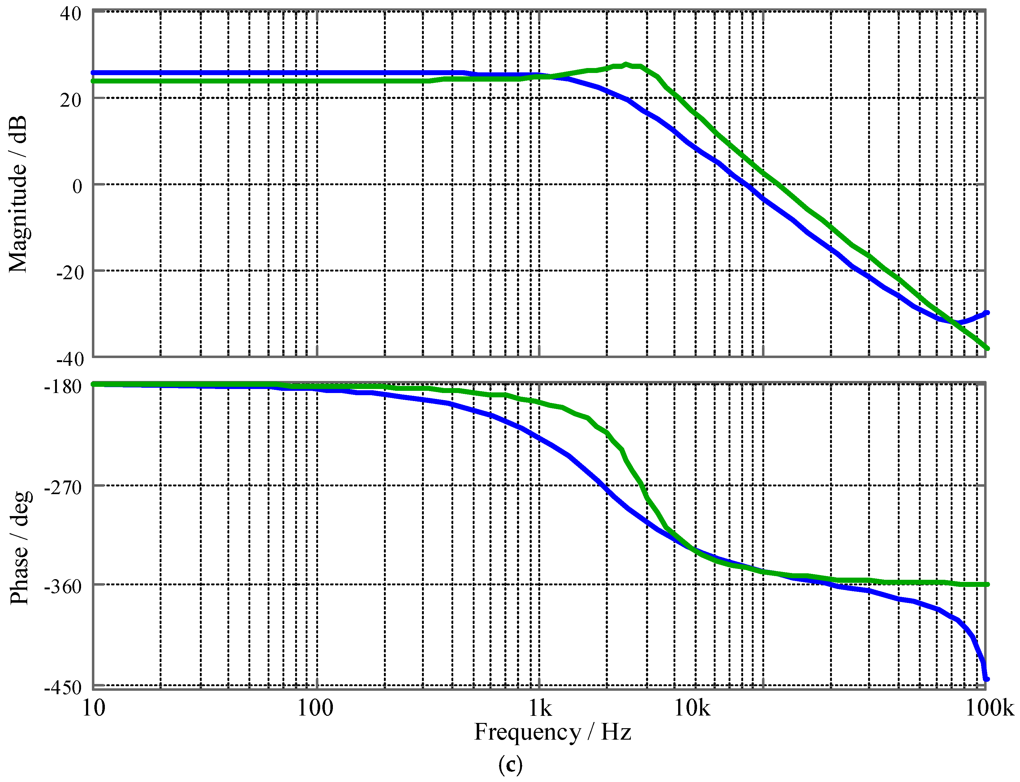
The frequency response curves using the small signal model and simplified model are given in Figure 4 to verify the effectiveness of the proposed model. The frequency response characteristics from below to above the resonant frequency in both models are the same at the low frequency range, verifying the accuracy of the proposed simplified model. At medium frequency, the characteristics of the simplified mode are similar to the traditional two-order transfer function: the magnetic falls with an overshoot and phase falls quickly from −180° to −360°, since frequency is negatively correlated with the output voltage, creating a −180° difference with the normal positive correlation transfer function. The small signal model is similar to the proposed simplified model especially in medium frequency range especially under resonant frequency operation conditions. In the high-frequency range, the proposed model frequency response characteristics are much different from the small signal model, especially the phase performance since the simplified model ignores the dynamic response of the resonant tank. Due to the large output capacitor, the harmonics at high frequencies would be suppressed. Thus, the simplified model is still accurate enough to guide controller design and analysis.
4. Rectifier Current Control
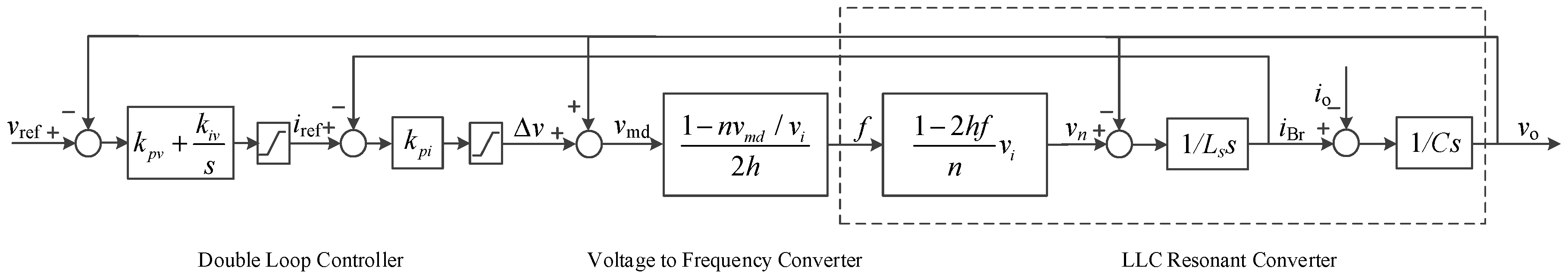
The traditional single-loop voltage control strategy can be used to achieve the expected voltage but with some disadvantages. (1) The single-loop control strategy cannot suppress the resonant peaks of the system transfer function. Since the LLC resonant converter is a two-order model as shown in Section 3, the small inner resistor in the single-loop control strategy cannot suppress the resonant oscillation, making the converter unstable. (2) Large resonant currents may appear during the control process, which could damage the converter since the resonant currents are out of control. Therefore, a double-loop control strategy is proposed in this paper, adding a rectifier current feedback controller to increase the closed-loop control system’s damping and limit the resonant currents during the control process. The block diagram of the control strategy is shown in Figure 5.
kpv and kiv are respectively the proportion and integration parameters of the outer voltage controller and kpi is the proportion parameters of the inner current controller. The voltage error between the reference and output voltage is calculated and sent to the PI controller, establishing the reference resonant current, which is limited by the saturation to protect the converter from large currents. The P controller of the rectifier current feedback is used to generate the regulation values, which can increase the system’s damping. The output voltage feedforward can improve the system’s dynamic response. Then, the inner transfer function can be expressed as follows:
The P parameter of the rectifier current feedback controller can be regarded as the inner resister. The higher P value can extend the bandwidth of the system to effectively suppress the resonant oscillation and improve the dynamic response performance. However, the higher bandwidth also reduces the ability to suppress the influence of high frequency harmonics, making the converter more unstable. The outer controller uses the output voltage feedback, which contains a PI controller to achieve steady, dynamic high performance. The closed-loop transfer function of the system can be written as follows:
The larger proportion value can improve the dynamic performance and the accuracy of the steady state. The larger integration value can eliminate the steady state error but also causes resonant oscillation, making the converter more unstable. In order to design the controller, the pole placement method is used to achieve these controller parameters. As shown in Figure 5, there are three controller parameters to design, and the characteristic equation is a three-order equation as shown in Equation (19). Thus these parameters can be obtained based on the placements of these poles. Assuming the damping ratio is ζ and the natural frequency is ωn, the expected characteristic equation can be written as follows:
The third pole kωn is placed far away from the predominant pole and k = 3~5. The pair of the predominant poles are decided by the damping ratio and natural frequency. Then, the controller parameters can be obtained as follows:
The equal Ls is derived from Equation (14) based on the converters parameters. k is usually 3~5 to make the non-dominant pole far away from the dominant poles. ζ is the damping ratio, which is larger than 0.7 to eliminate the resonant peak of the frequency curve. ωn is the natural frequency which is 500~1000 rad/s to achieve a good dynamical performance. When the proposed double-loop controller is used, the resonant peak is effectively suppressed due to the large damping caused by the rectifier current feedback controller.
5. Simulation and Experiments
A simulation model of the LLC resonant converter is built in MATLAB (R2013b, The MathWorks, Inc., Natick, MA. USA) to verify the effectiveness of the proposed control strategy. The main parameters of the model are shown in Table 1. The transformer ratio is 10:1:1 so that the rated voltage gain can be 1 and the converter operates at the resonant frequency achieving high efficiency. The resonant inductor is 86 μH, the resonant capacitor is 23.5 nF and the magnetic inductor is 266.5 μH. The output capacitor is 3.96 mF, which is large enough to maintain the output voltage. Thus the resonant frequency is about 112 kHz. The equal output inductor is about 0.8 mH based on Equation (14). The oscillation frequency of the LLC resonant converter is about 2.8 kHz.
The output voltage waveforms using the single-loop control strategy are shown in Figure 6a, presenting 5 mV for voltage ripple amplitude and 2.5 kHz for oscillation frequency, which is similar to the calculated results, showing the single-loop control has trouble suppressing the resonant oscillation. The output voltage waveforms using the rectifier current feedback is shown in Figure 6b. The inner feedback control can effectively suppress the oscillation, decreasing the amplitude of the voltage ripple from 5 mV to 2.5 mV, verifying the correctness of the proposed simplified model and showing the effective performance of the proposed double-loop control strategy.
A 200 W prototype was built to verify the proposed control strategy. The parameters are the same with as in Table 1. The controller is implemented on the F28335 microcontroller with 10 kHz of the control frequency and 100~300 kHz of the switching frequency range. The proposed control method is shown in Figure 5.
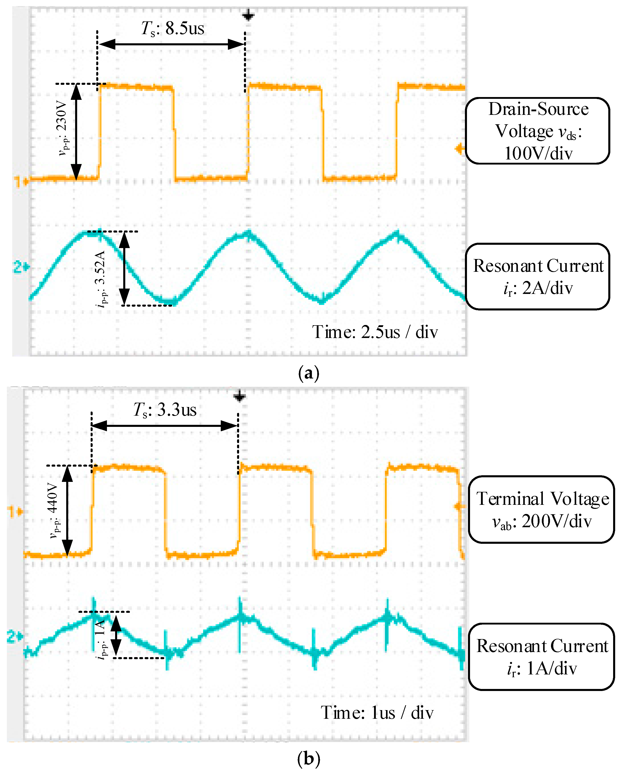
The experimental waveforms of switcher voltage and resonant current at heavy loads are shown in Figure 7a, where the input voltage is 220 V and the output currents is 8 A with 117 kHz of the switching frequency. As shown in the figure, when the switcher turns on, the resonant currents are negative and flow through the anti-diode of the switcher, producing ZVS. When the loads are light, the experimental waveforms of terminal voltage and resonant current are shown in Figure 7b, where the output currents are only 1 A with 300 kHz switching frequency. Due to the light loads, the resonant currents are similar to the magnetic currents, which rise linearly when the switchers turn on and fall linearly as the switchers turn off. Under both conditions, the switchers can achieve ZVS.
The experimental waveforms using the single-loop control strategy are shown in Figure 8a, where the input voltage is 220 V and output voltage is regulated to 24 V with a load step from zero to 8 A. The output voltage and current against the step up loads can reach the steady state again in the period of 10.8 ms. The maximum voltage droop is about 6.8 V. Due to the small damping, the output voltage has large voltage ripples. The control performance is not very good. Then, the double-loop control strategy is implemented on this prototype. The voltage and current waveforms against the step up loads are shown in Figure 8b under the same operation conditions with Figure 8a. Due to the added inner rectifier current feedback control, the settling time is 8.6 ms and voltage droop is 4.8 V showing better dynamic response performances compared with the single-loop control strategy. Meanwhile the output voltage has small ripples. The good output performances verify the effectiveness of the proposed control strategy.
6. Conclusions
This paper proposed a double-loop control strategy for the LLC resonant converter by using an added rectifier current feedback inner controller to suppress the oscillation and protect the converter from large currents, achieving high dynamical performance based on a simplified linearized model to reduce the model orders from seven to two. This simplifies the analysis and design of the converter. The main contributions of this paper are as follows:
- (1)
- A two-order, linearized model of the LLC resonant converter is built based on the EDF method with the resonant tank as a controlled voltage source which provides energy for the output capacitor and loads. This sample model can simplify the analysis and design of the LLC resonant converter, which is very useful for the engineer.
- (2)
- A double-loop control strategy for the LLC resonant converter is proposed, using an added rectifier current feedback inner controller to improve the converter damping and protect the converter from large currents, achieving better performance compared with the traditional single-loop control scheme.
All these contributions can effectively improve the design of the LLC resonant converter. The simulation and experimental results verify the effectiveness of the proposed control strategy. The settling time of the LLC resonant converter is reduced from 10.8 ms to 8.6 ms and the voltage droop is reduced from 6.8 V to 4.8 V using the double-loop control strategy. The proposed control strategy can also be used for other converters.
Acknowledgments
This work was supported in part by the National Natural Science Foundation of China under Project of 51707138 and 51507114, and in part by the National Key Research and Development Plan under Project of 2017YFB1201002.
Author Contributions
Zhijian Fang and Junhua Wang conceived and designed the experiments; Guozheng Hu and Liangle Xiao performed the experiments; Zhijian Fang and Shanxu Duan analyzed the data; Junhua Wang and Qisheng Liu contributed reagents/materials/analysis tools; Zhijian Fang wrote the paper.
Conflicts of Interest
The authors declare no conflict of interest.
References
- An, L.; Lu, D.D.C. Analysis of DC Bus Capacitor Current Ripple Reduction in Basic DC/DC Cascaded Two-Stage Power Converters. IEEE Trans. Ind. Electron. 2016, 63, 7467–7477. [Google Scholar] [CrossRef]
- Xue, F.; Yu, R.; Huang, A.Q. A 98.3% Efficient GaN Isolated Bidirectional DC-DC Converter for DC Microgrid Energy Storage System Applications. IEEE Trans. Ind. Electron. 2017, 64, 9094–9103. [Google Scholar] [CrossRef]
- Kumar, M.; Gupta, R. Stability and Sensitivity Analysis of Uniformly Sampled DC-DC Converter with Circuit Parasitics. IEEE Trans. Circuits Syst. I Regul. Pap. 2016, 63, 2086–2097. [Google Scholar] [CrossRef]
- Shafiei, N.; Ordonez, M.; Craciun, M.; Botting, C.; Edington, M. Burst Mode Elimination in High-Power LLC Resonant Battery Charger for Electric Vehicles. IEEE Trans. Power Electron. 2016, 31, 1173–1188. [Google Scholar] [CrossRef]
- Zhang, L.; Born, R.; Zhao, X.; Gu, B.; Lai, J.S. A Parabolic Voltage Control Strategy for Burst Mode Converters with Constant Burst Frequency and Eliminated Audible Noise. IEEE Trans. Power Electron. 2016, 31, 8572–8580. [Google Scholar] [CrossRef]
- Fan, S.; Xue, Z.; Lu, H.; Song, Y.; Li, H.; Geng, L. Area-Efficient On-Chip DC/DC Converter with Multiple-Output for Bio-Medical Applications. IEEE Trans. Circuits Syst. I Regul. Pap. 2014, 61, 3298–3308. [Google Scholar] [CrossRef]
- Sun, X.; Li, X.; Shen, Y.; Wang, B.; Guo, X. Dual-Bridge LLC Resonant Converter with Fixed-Frequency PWM Control for Wide Input Applications. IEEE Trans. Power Electron. 2017, 32, 69–80. [Google Scholar] [CrossRef]
- Zahid, Z.U.; Dalala, Z.M.; Chen, R.; Chen, B.; Lai, J.S. Design of Bidirectional DC/DC Resonant Converter for Vehicle-to-Grid (V2G) Applications. IEEE Trans. Transp. Electrif. 2015, 1, 232–244. [Google Scholar] [CrossRef]
- Haga, H.; Kurokawa, F. Modulation Method of a Full-Bridge Three-Level LLC Resonant Converter for Battery Charger of Electrical Vehicles. IEEE Trans. Power Electron. 2017, 32, 2498–2507. [Google Scholar] [CrossRef]
- Yang, B.; Lee, F.C.; Zhang, A.; Huang, G. LLC resonant converter for front end DC/DC conversion. In Proceedings of the Seventeenth Annual IEEE Applied Power Electronics Conference and Exposition, Dallas, TX, USA, 10–14 March 2002; Volume 2, pp. 1108–1112. [Google Scholar]
- De Groot, H.; Janssen, E.; Pagano, R.; Schetters, K. Design of a 1-MHz LLC Resonant Converter Based on a DSP-Driven SOI Half-Bridge Power MOS Module. IEEE Trans. Power Electron. 2007, 22, 2307–2320. [Google Scholar] [CrossRef]
- Kundu, U.; Yenduri, K.; Sensarma, P. Accurate ZVS Analysis for Magnetic Design and Efficiency Improvement of Full-Bridge LLC Resonant Converter. IEEE Trans. Power Electron. 2017, 32, 1703–1706. [Google Scholar] [CrossRef]
- Kang, S.W.; Cho, B.H. Digitally Implemented Charge Control for LLC Resonant Converters. IEEE Trans. Ind. Electron. 2017, 64, 6159–6168. [Google Scholar] [CrossRef]
- Kurokawa, F.; Murata, K. A new quick response digital modified P-I-D control LLC resonant converter for DC power supply system. In Proceedings of the 2011 IEEE Ninth International Conference on Power Electronics and Drive Systems, Singapore, 5–8 December 2011; pp. 35–39. [Google Scholar]
- Liu, C.L.; Chiu, Y.H.; Lo, Y.F.; Wang, S.C.; Liu, Y.H. Design and implementation of a digitally-controlled LLC resonant converter for battery charging applications. In Proceedings of the 2013 IEEE 10th International Conference on Power Electronics and Drive Systems (PEDS), Kitakyushu, Japan, 22–25 April 2013; pp. 804–808. [Google Scholar]
- Shahzad, M.I.; Iqbal, S.; Taib, S. LLC series resonant converter with PID controller for battery charging application. In Proceedings of the 2014 IEEE Conference on Energy Conversion (CENCON), Johor Bahru, Malaysia, 13–14 October 2014; pp. 84–89. [Google Scholar]
- Jang, J.; Joung, M.; Choi, B.; Hong, S.; Lee, S. Dynamic analysis and control design of optocoupler-isolated LLC series resonant converters with wide input and load variations. In Proceedings of the 2009 IEEE Energy Conversion Congress and Exposition, San Jose, CA, USA, 20–24 September 2009; pp. 758–765. [Google Scholar]
- Jang, J.; Pidaparthy, S.K.; Choi, B. Current mode control for LLC series resonant dc-to-dc converters. In Proceedings of the 2011 Twenty-Sixth Annual IEEE Applied Power Electronics Conference and Exposition (APEC), Fort Worth, TX, USA, 6–11 March 2011; pp. 21–27. [Google Scholar]
- Jang, J.; Kumar, P.S.; Kim, D.; Choi, B. Average current-mode control for LLC series resonant dc-to-dc converters. In Proceedings of the 7th International Power Electronics and Motion Control Conference, Harbin, China, 2–5 June 2012; pp. 923–930. [Google Scholar]
- Buccella, C.; Cecati, C.; Latafat, H.; Pepe, P.; Razi, K. Observer-Based Control of LLC DC/DC Resonant Converter Using Extended Describing Functions. IEEE Trans. Power Electron. 2015, 30, 5881–5891. [Google Scholar] [CrossRef]
- Ma, H.; Liu, Q.; Guo, J. A sliding-mode control scheme for llc resonant DC/DC converter with fast transient response. In Proceedings of the IECON 2012—38th Annual Conference on IEEE Industrial Electronics Society, Montreal, QC, Canada, 25–28 October 2012; pp. 162–167. [Google Scholar]
- Hu, Z.; Liu, Y.F.; Sen, P.C. Bang-Bang charge control for LLC resonant converters. In Proceedings of the 2013 IEEE Energy Conversion Congress and Exposition, Denver, CO, USA, 15–19 September 2013; pp. 140–146. [Google Scholar]
- Nishimura, T.; Adachi, Y.; Ohta, Y.; Higuchi, K.; Takegami, E.; Tomioka, S.; Jirasereeamornkul, K.; Chamnongthai, K. Robust digital control for an LLC current-resonant DC-DC converter. In Proceedings of the 2012 9th International Conference on Electrical Engineering/Electronics, Computer, Telecommunications and Information Technology, Phetchaburi, Thailand, 16–18 May 2012; pp. 1–4. [Google Scholar]
- Buccella, C.; Cecati, C.; Latafat, H.; Razi, K. Comparative transient response analysis of LLC resonant converter controlled by adaptive PID and fuzzy logic controllers. In Proceedings of the IECON 2012—38th Annual Conference on IEEE Industrial Electronics Society, Montreal, QC, Canada, 25–28 October 2012; pp. 4729–4734. [Google Scholar]
- Fang, Z.; Wang, J.; Duan, S.; Liu, K.; Cai, T. Control of an LLC Resonant Converter Using Load Feedback Linearization. IEEE Trans. Power Electron. 2018, 33, 887–898. [Google Scholar] [CrossRef]
- Feng, W.; Lee, F.C.; Mattavelli, P. Optimal Trajectory Control of Burst Mode for LLC Resonant Converter. IEEE Trans. Power Electron. 2013, 28, 457–466. [Google Scholar] [CrossRef]
- Feng, W.; Lee, F.C. Optimal Trajectory Control of LLC Resonant Converters for Soft Start-Up. IEEE Trans. Power Electron. 2014, 29, 1461–1468. [Google Scholar] [CrossRef]
- Feng, W.; Lee, F.C.; Mattavelli, P. Optimal Trajectory Control of LLC Resonant Converters for LED PWM Dimming. IEEE Trans. Power Electron. 2014, 29, 979–987. [Google Scholar] [CrossRef]
- Qiu, Y.; Chen, X.; Zhong, C.; Qi, C. Uniform Models of PWM DC-DC Converters for Discontinuous Conduction Mode Considering Parasitics. IEEE Trans. Ind. Electron. 2014, 61, 6071–6080. [Google Scholar] [CrossRef]
- Verghese, G.C.; Elbuluk, M.E.; Kassakian, J.G. A General Approach to Sampled-Data Modeling for Power Electronic Circuits. IEEE Trans. Power Electron. 1986, 1, 76–89. [Google Scholar] [CrossRef]
- Yang, B.; Lee, F.C.; Jovanovic, M. Small-signal analysis for LLC resonant converter. In Proceedings of the CPES Seminar, Blacksburg, VA, USA, 27–29 April 2003; pp. 144–149. [Google Scholar]
- Chang, C.H.; Chang, E.C.; Cheng, C.A.; Cheng, H.L.; Lin, S.C. Small Signal Modeling of LLC Resonant Converters Based on Extended Describing Function. In Proceedings of the 2012 International Symposium on Computer, Consumer and Control, Taichung, Taiwan, 4–6 June 2012; pp. 365–368. [Google Scholar]
- Cheng, B.; Musavi, F.; Dunford, W.G. Novel small signal modeling and control of an LLC resonant converter. In Proceedings of the 2014 IEEE Applied Power Electronics Conference and Exposition, Fort Worth, TX, USA, 16–20 March 2014; pp. 2828–2834. [Google Scholar]
Figure 1.
Circuit block diagram of LLC resonant converter.
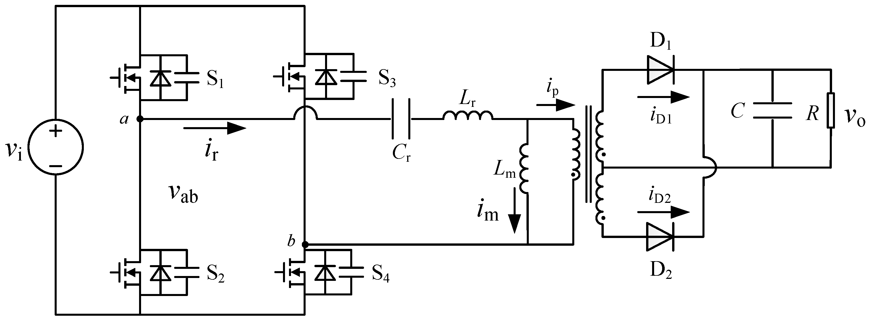
Figure 2.
Operation waveforms of LLC resonant converter.

Figure 3.
Equal circuit of LLC resonant converter.
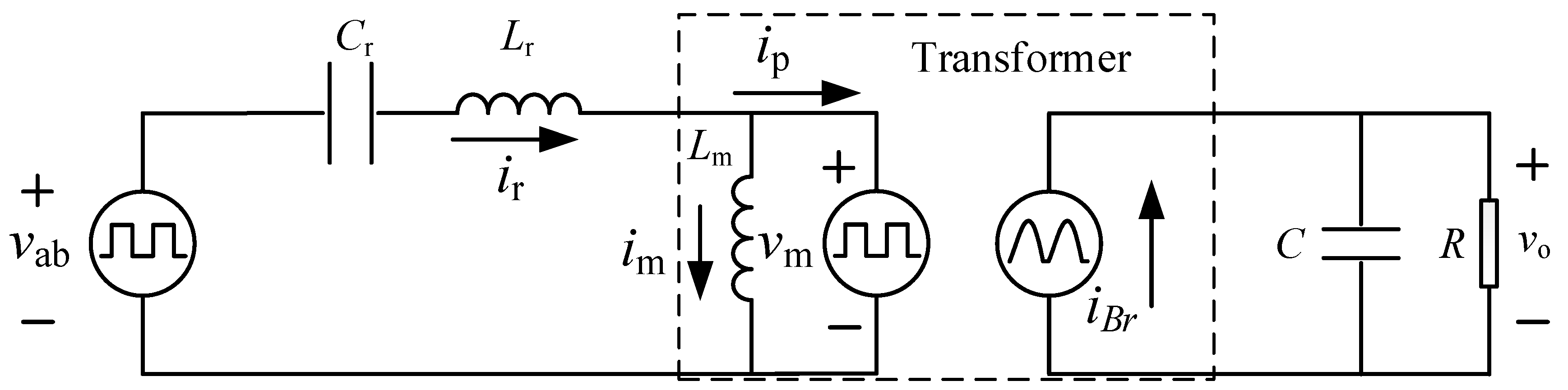
Figure 4.
The bode plot of output voltage vo with respect to normalized switching frequency fs/fr using the small-signal model (blue line) and simplified model (green line): (a) below resonant frequency (fs = 0.8fr); (b) at resonant frequency (fs = fr); (c) above resonant frequency (fs = 1.2fr).
Figure 4.
The bode plot of output voltage vo with respect to normalized switching frequency fs/fr using the small-signal model (blue line) and simplified model (green line): (a) below resonant frequency (fs = 0.8fr); (b) at resonant frequency (fs = fr); (c) above resonant frequency (fs = 1.2fr).


Figure 5.
Double-loop control strategy of LLC resonant converter.

Figure 6.
Simulation waveforms of output voltage for (a) a single-loop controller and (b) a double-loop controller.
Figure 6.
Simulation waveforms of output voltage for (a) a single-loop controller and (b) a double-loop controller.
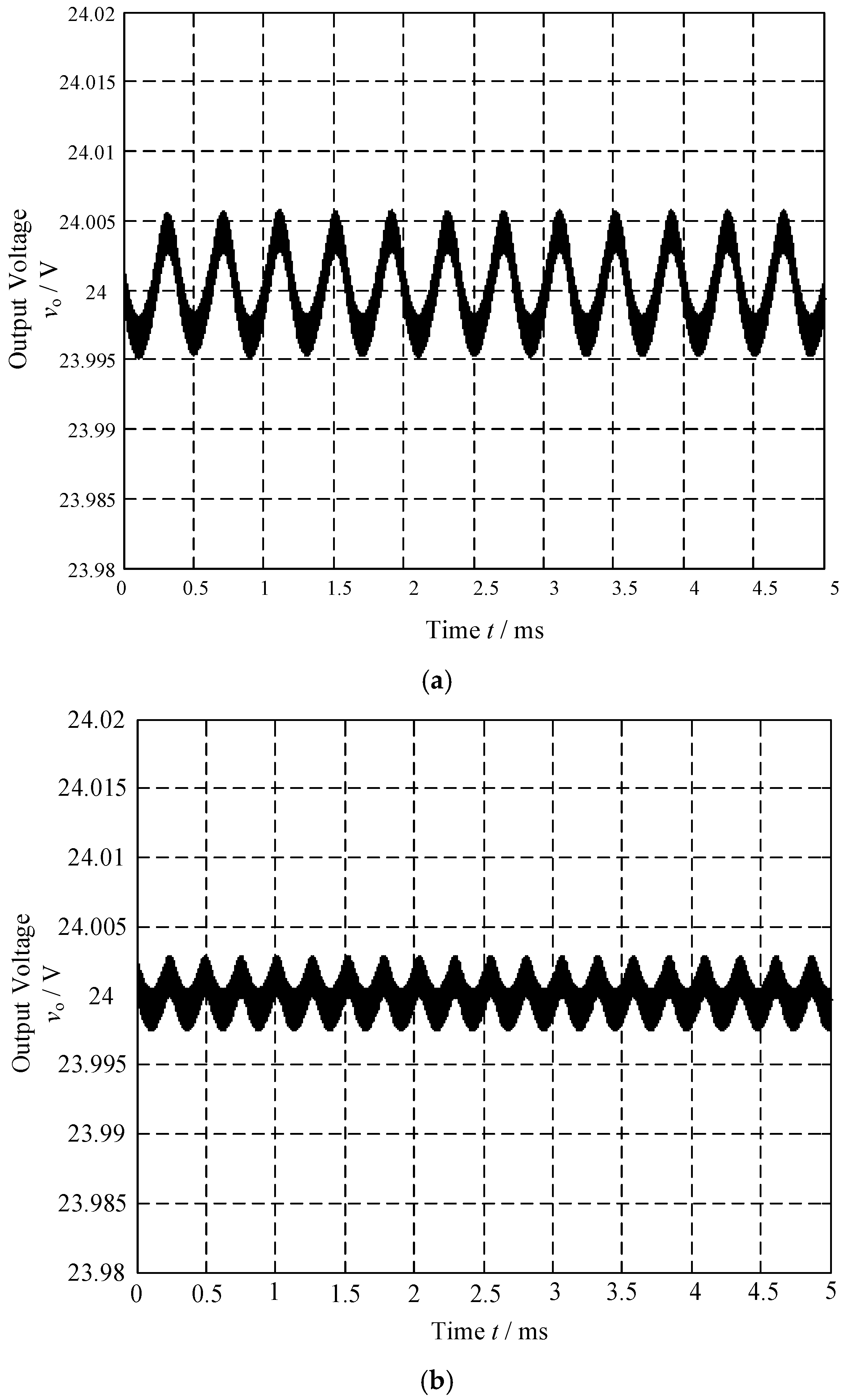
Figure 7.
Waveforms of switcher voltage and current (a) with heavy loads and (b) with light loads.

Figure 8.
Experimental waveforms of output voltage and current for (a) a single-loop controller and (b) a double-loop controller.
Figure 8.
Experimental waveforms of output voltage and current for (a) a single-loop controller and (b) a double-loop controller.


Table 1.
Units for magnetic properties.
| Parameter | Value |
|---|---|
| Input voltage | 240 V |
| Output voltage | 24 V |
| Output current | 8 A |
| Transformer ratio | 10:1:1 |
| Resonant inductor | 86 μH |
| Resonant capacitor | 23.5 nF |
| Magnetic inductor | 266.5 μH |
| Output capacitor | 3.96 mF |
© 2018 by the authors. Licensee MDPI, Basel, Switzerland. This article is an open access article distributed under the terms and conditions of the Creative Commons Attribution (CC BY) license (http://creativecommons.org/licenses/by/4.0/).
Share and Cite
MDPI and ACS Style
Fang, Z.; Wang, J.; Duan, S.; Xiao, L.; Hu, G.; Liu, Q. Rectifier Current Control for an LLC Resonant Converter Based on a Simplified Linearized Model. Energies 2018, 11, 579. https://doi.org/10.3390/en11030579
AMA Style
Fang Z, Wang J, Duan S, Xiao L, Hu G, Liu Q. Rectifier Current Control for an LLC Resonant Converter Based on a Simplified Linearized Model. Energies. 2018; 11(3):579. https://doi.org/10.3390/en11030579
Chicago/Turabian StyleFang, Zhijian, Junhua Wang, Shanxu Duan, Liangle Xiao, Guozheng Hu, and Qisheng Liu. 2018. "Rectifier Current Control for an LLC Resonant Converter Based on a Simplified Linearized Model" Energies 11, no. 3: 579. https://doi.org/10.3390/en11030579
Note that from the first issue of 2016, this journal uses article numbers instead of page numbers. See further details here.