1. Introduction
Line commutated converters for high voltage direct currents (LCC-HVDC) have been widely applied due to their large capacity and low construction costs. Voltage source converters for high voltage direct current (VSC-HVDC) power transmission have also been rapidly developed because of their advantages decoupling the control of active and reactive power and no risk of commutation failure. With the increase in DC transmission projects, different types of HVDC systems tend to feed into power grids with short electrical distances. Thus, hybrid dual-infeed or multi-infeed HVDC systems have emerged worldwide [
1,
2].
Given that LCC-HVDCs are sensitive to AC grid voltage fluctuations, commutation failure is likely to occur at the inverter of the LCC-HVDC system during grid fault or voltage distortion, thereby leading to DC voltage drop, temporary overcurrent in the valves, and other adverse factors, which may affect the safe operation of the DC system. If the commutation failure cannot be eliminated effectively, then continuous commutation failure will occur, leading to converter blocking [
3].
Over the past few years, considerable research on how to eliminate commutation failure in LCC-HVDC systems has been conducted [
4,
5,
6,
7,
8,
9]. In [
4], a commutation failure prediction control algorithm based on the rapid detection of voltage dips in AC systems was proposed, which reduced the risk of commutation failure by reducing the firing angle of the inverter. On this basis, an improved commutation failure prediction control algorithm based on variations in DC current was proposed to improve immunity to commutation failure [
5]. In [
6], a power component fault detection method and improved voltage dependent current order limiter (VDCOL) were developed to mitigate commutation failure. This method mainly improved fault detection sensitivity and provided an advanced firing angle or enhanced current-order control methods to make the LCC-HVDC less susceptible to commutation failure. However, these methods rely heavily on the fault detection rate. Existing studies show that the first commutation failure is generally unavoidable and that continuous commutation failure after grid fault is the direct cause of converter blocking [
7]. Focusing on the risk of continuous commutation failure, one study [
8] achieved the suppression of continuous commutation failure by introducing a fuzzy controller to adjust the extinction angle at the inverter. In another study [
9], a DC limiting strategy was designed based on virtual resistance to avoid continuous commutation failure according to variations in DC voltage.
In addition to the suppression of commutation failure by improving LCC-HVDC control, the addition of reactive power compensation devices has a good effect on commutation failure suppression. In [
10], the performance of an LCC-HVDC system containing a static compensator (STATCOM) was investigated. Immunity to commutation failure was improved by adding the STATCOM to the AC side of the inverter. A STATCOM reactive power control strategy based on variation of the extinction angle of the inverter was designed in [
11], and continuous commutation failure suppression capability was improved. However, reactive power compensation has some inherent drawbacks, for example, the response speed of static var compensators under grid fault is relatively slow, the reactive compensation capacity of STATCOM is limited, and the large capacity of STATCOM significantly increases the investment and operation cost of the power grid [
12].
In a hybrid dual-infeed HVDC system, owing to active and reactive power decoupling control characteristics, VSC-HVDC systems have the ability to support grid voltage and provide an effective way to mitigate continuous commutation failure. Based on the calculation method of the effective short-circuit ratio (SCR) of the hybrid dual-infeed HVDC system, [
13] proposed a VSC-HVDC reactive power control strategy to improve the voltage stability of the AC grid. Based on the variation of the extinction angle in the LCC-HVDC inverter during grid fault, a coordinated reactive-power control strategy based on extinction angle was proposed, which could reduce the commutation failure risk of the LCC-HVDC [
14]. However, in the above studies, the reactive power control of VSC-HVDC has only been discussed qualitatively. The existing research does not fully consider the quantitative aspects of reactive power control and the frequency constraint of the sending-end grid.
In this study, a commutation failure suppression method of a hybrid dual-infeed HVDC system under grid fault was investigated, and the contribution of the reactive power control capacity of VSC-HVDCs to the mitigation of commutation failure was quantitatively analyzed. First, the reactive power demand required to avoid commutation failure under a grid fault was analyzed. Combined with the maximum current-limiting control constraint of the VSC-HVDC inverter and the primary frequency control capability of the sending-end grid, a controllable operation region and commutation failure suppression method was proposed. Finally, a hybrid dual-infeed HVDC system simulation model based on PSCAD/EMTDC simulation software was built to verify the effectiveness of the proposed control method. The simulation results showed that the proposed control method could improve the control capability of the VSC-HVDC system and effectively improve the suppression capability of continuous commutation failure in hybrid dual-infeed HVDC systems.
2. Hybrid Dual-Infeed HVDC System Model
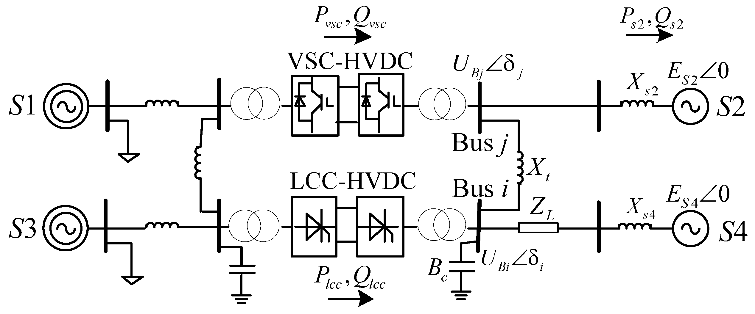
The structure of the hybrid dual-infeed HVDC transmission system, which consists of an LCC-HVDC and VSC-HVDC feeding into an AC grid, is shown in
Figure 1. In
Figure 1, the sending-end grids are represented by
S1 and
S3, and the receiving-end grids are represented by
S2 and
S4. The equivalent reactance of
S2 and
S4 is represented by
Xs2 and
Xs4, respectively. The equivalent electromotive force of
S2 and
S4 is represented by
and
, respectively.
and
are the AC bus voltages of the VSC-HVDC and LCC-HVDC, respectively.
Xt is the equivalent reactance of the tie-line between buses
i and
j.
In the LCC-HVDC system, thyristors are used as the commutation element, which have no self-turn-off capability. The LCC-HVDC system rectifier generally adopts constant DC current or constant power control, and the control strategy of the inverter is generally a constant extinction angle or constant DC current control. The DC current
Id and DC voltage
Ud of the LCC-HVDC system can be expressed as follows [
15]:
where
UBi is the voltage of the commutated bus at the inverter side,
γ is the extinction angle of the inverter,
μ is the commutation overlap angle of the inverter,
k is the transformer ratio, and
XT is the commutating reactance.
Under steady-state operating conditions, the reactive power,
Qd, consumed by the LCC-HVDC system can reach 40–60% of the transmitted active power [
16]. This part of the reactive power consumption is usually provided by the reactive power compensation device and filter.
where
Plcc and
Qlcc are the active and reactive power outputs of the LCC-HVDC inverter, respectively.
Qlcc is positive when the reactive power is transmitted by the inverter to the AC grid.
Qlcc is negative when the inverter absorbs reactive power from the AC grid.
Qc is the reactive power output of the compensation device,
Bc is the equivalent susceptance of the reactive power compensation device,
Qd is the reactive power consumption of the inverter, and
is the equivalent power factor angle.
In contrast to the control method of the LCC-HVDC system, the VSC-HVDC system adopts a voltage source converter based on fully controlled electronic devices, which can independently control active and reactive power and do not require reactive power compensation. Vector control is commonly adopted in the VSC-HVDC converter control strategy, which consists of the inner and outer loop current controls [
17]. According to the grid voltage directional vector control method, the
d-axis is oriented to the AC bus voltage, such that the active and reactive power outputs of the inverter can be expressed as follows:
where
UBj is the voltage of the AC bus at the inverter side of the VSC-HVDC; and
id and
iq are the active and reactive currents, respectively. The active and reactive power control of the VSC-HVDC inverter can be controlled independently by adjusting
id and
iq, respectively.
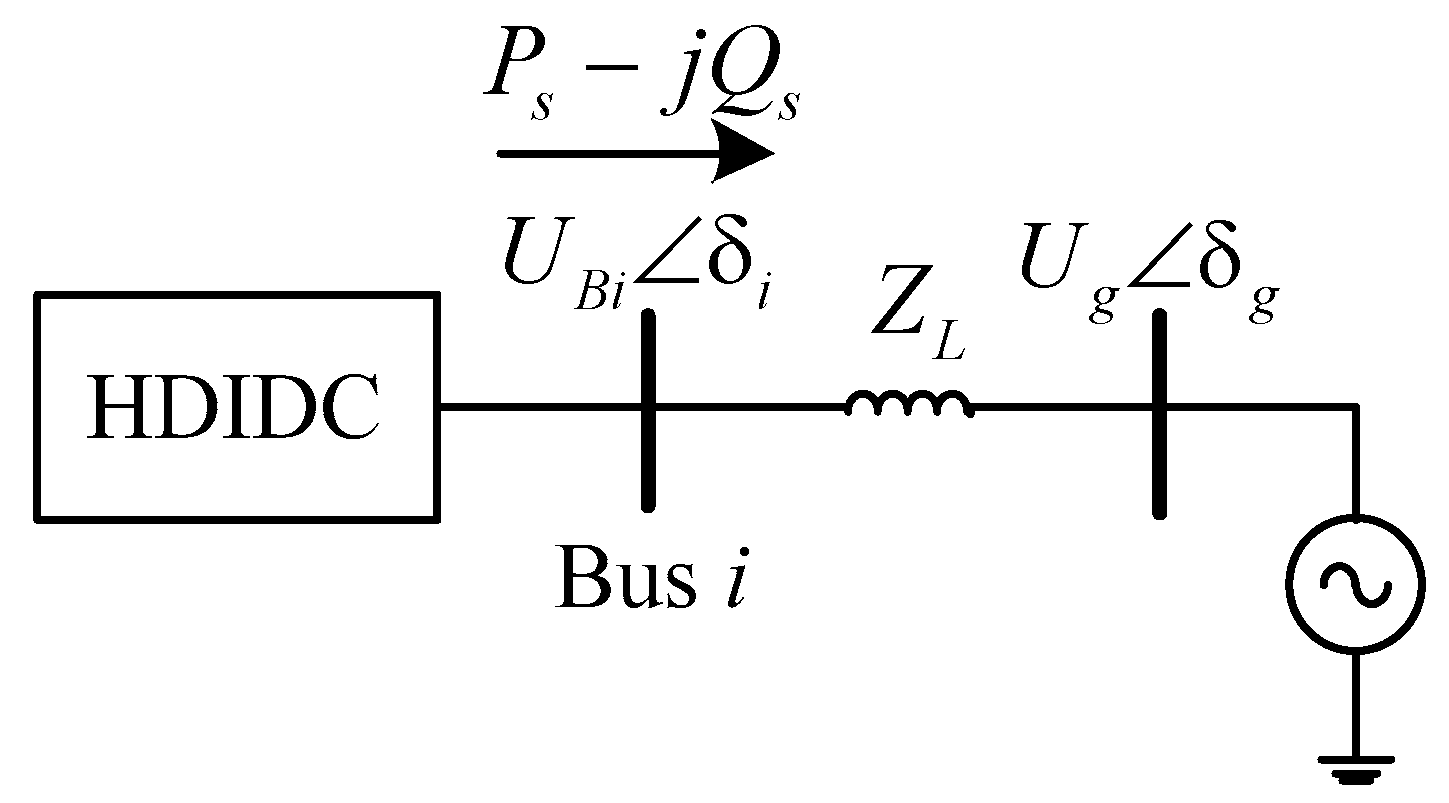
Given that the electrical distance between different commutated buses in the multi-infeed DC system is relatively small, the amplitude and phase angle difference between the commutated bus voltages is usually small. Therefore, the power loss of the tie-line can be neglected. The active and reactive power outputs from the hybrid dual-infeed HVDC system via bus
i to the AC grid include the sum of the output powers of the VSC-HVDC inverter, the LCC-HVDC inverter, and the AC system
S2.
where
Ps2 and
Qs2 are the active and reactive power outputs of the AC system
S2, respectively.
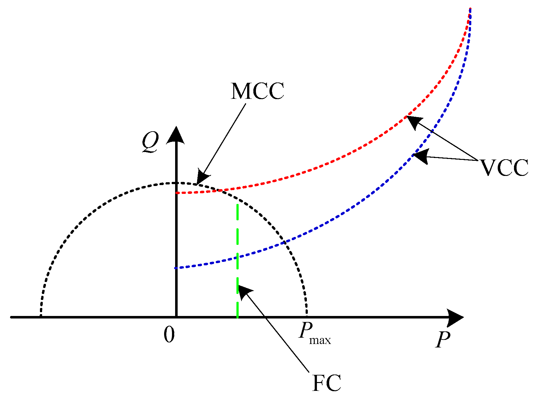
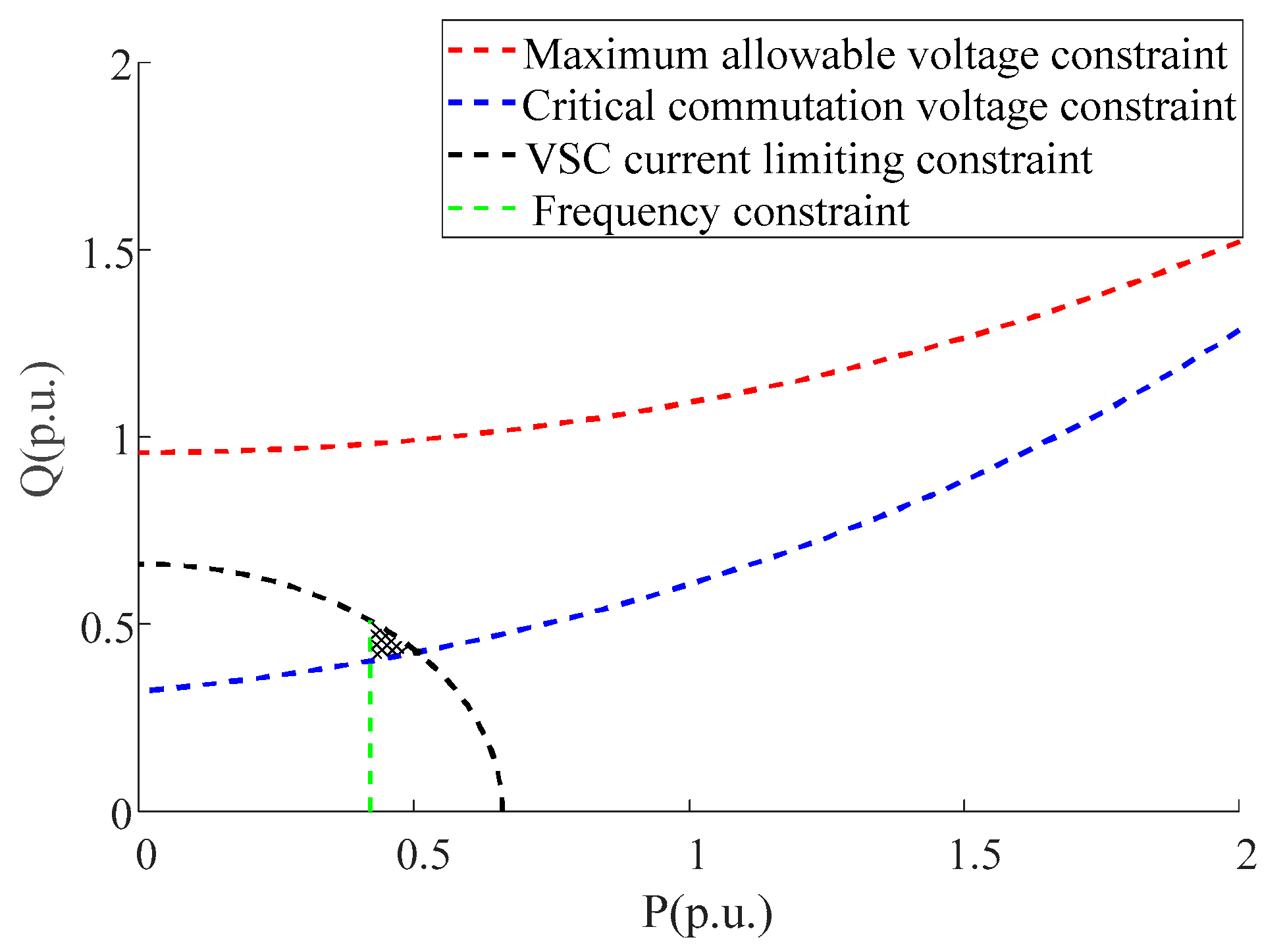
4. Commutation Failure Suppression Method Based on Controllable Operation Region
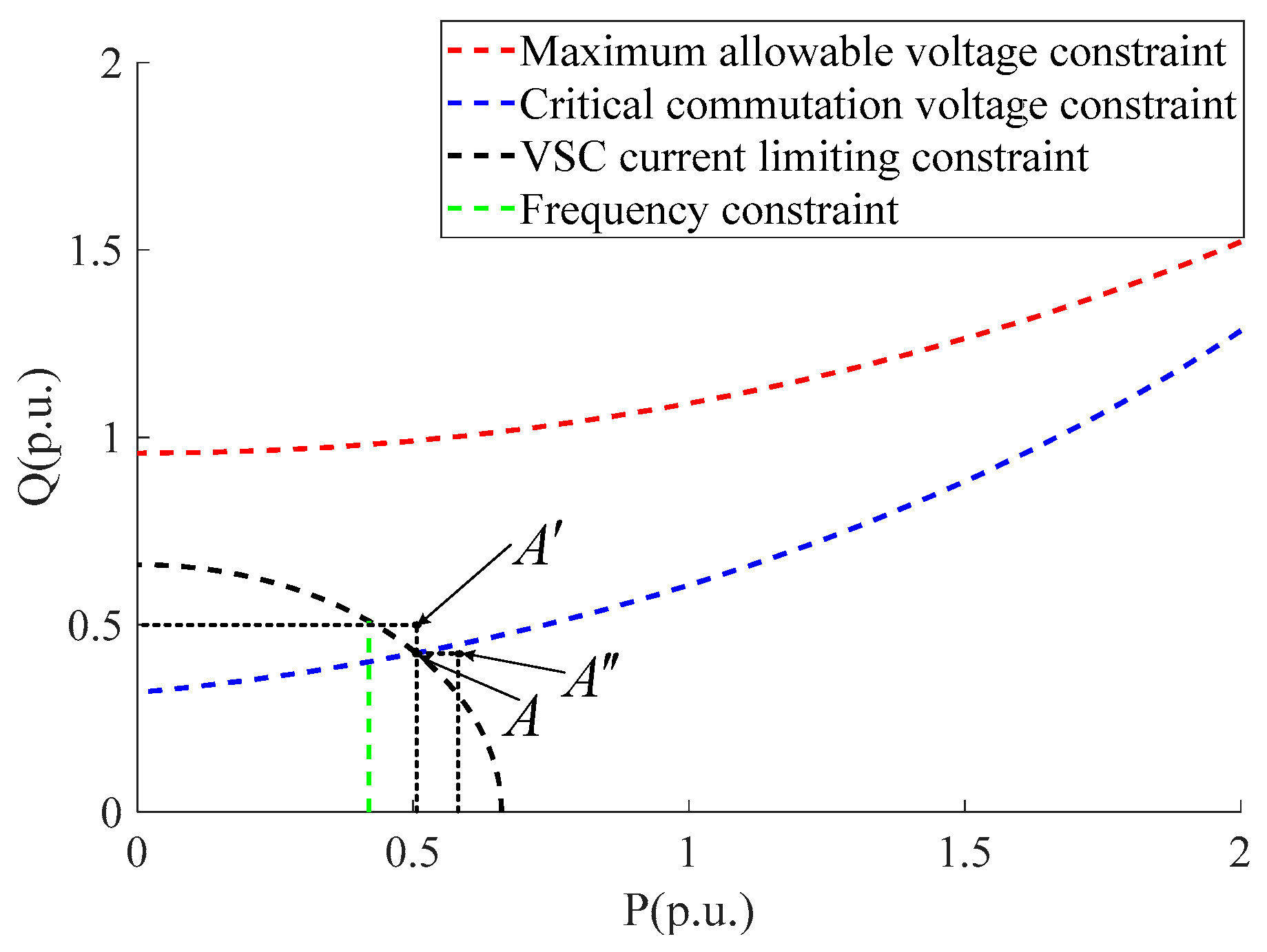
Based on the above analysis, the critical commutation voltage constraint (VCC) can be obtained by Equations (12) and (13). The power circle of the VSC-HVDC inverter under the maximum limiting current constraint (MCC) can be derived using Equation (16). The VSC-HVDC inverter active power constraint boundary, considering grid frequency constraints (FC), can be obtained using Equation (19). The intersection of the three constraints in the
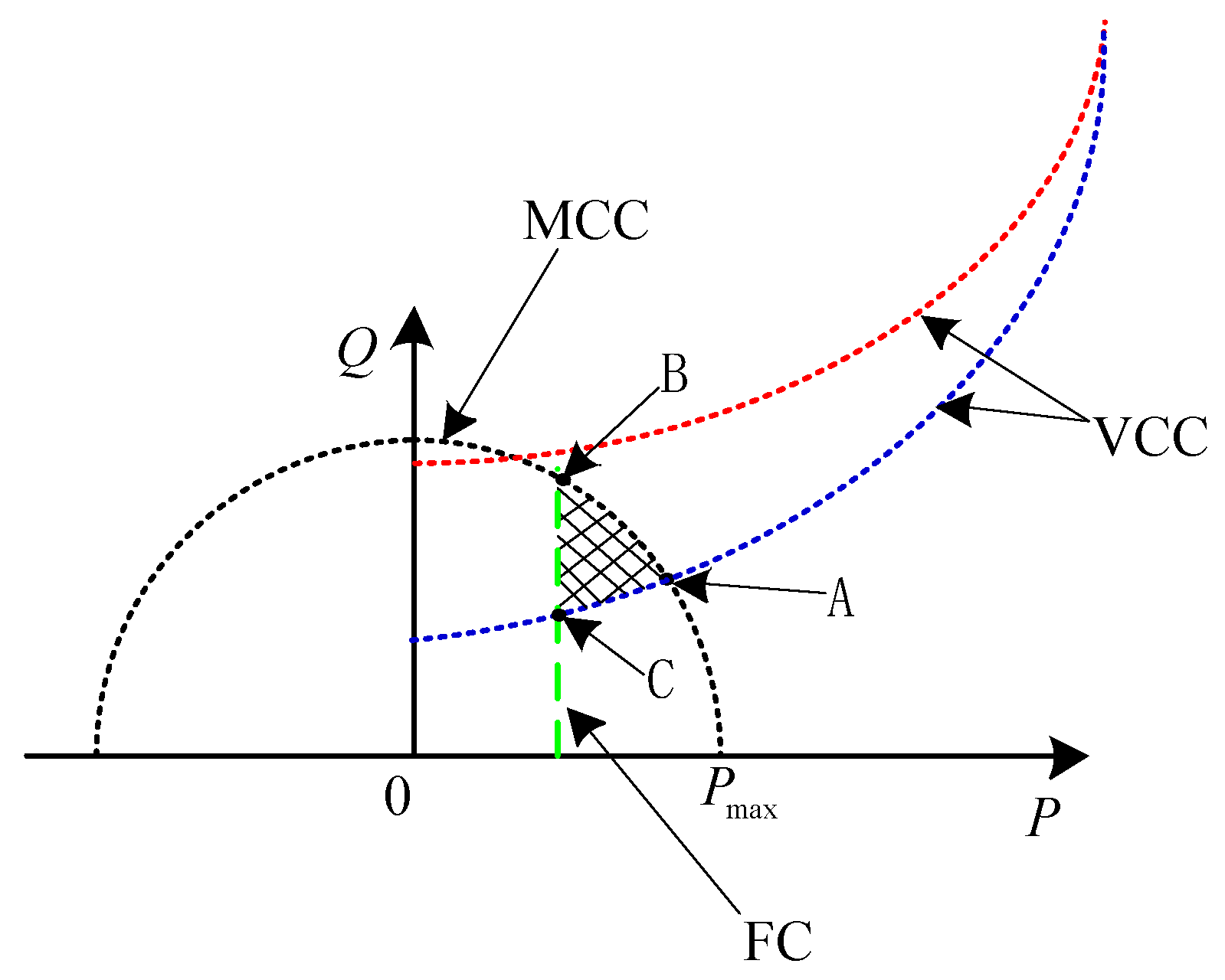
PQ coordinate is the controllable operation region of the VSC-HVDC inverter, which can avoid commutation failure and fulfill the frequency constraint of the sending-end grid, as shown in the shaded area surrounded by points A, B, and C, in
Figure 4.
Considering the decrease in transmitted active power by the LCC-HVDC system, the power operation point A will not only fulfill the boundary of avoiding commutation failure, but will also assure the maximum active power transmission capability of the VSC-HVDC. In this study, the power operation point A was selected as the control reference value of the VSC inverter. By combining Equations (12) and (16), the maximum active power operation point of the controllable operation region, which can fulfill the critical commutation voltage, can be obtained, as shown by point A in
Figure 4. The corresponding reactive power reference
can be expressed as follows:
where
If ∆ ≥ 0, then the controllable operation region that can avoid commutation failure exists. Combining Equations (16) and (19) yields the maximum reactive power operation point of the controllable operation region that fulfills the grid frequency constraint, as shown by point B in
Figure 5. The corresponding reactive power can be calculated as follows:
By further substituting Equation (22) into Equation (12), the critical voltage
Uglim of the fault point under maximum reactive power
Qvscmax can be obtained.
If the voltage amplitude of the fault point is lower than Uglim, then the reactive control capacity of the VSC inverter cannot fulfill the condition of avoiding commutation failure and the frequency constraint.
Thus, the reactive current
can be given by:
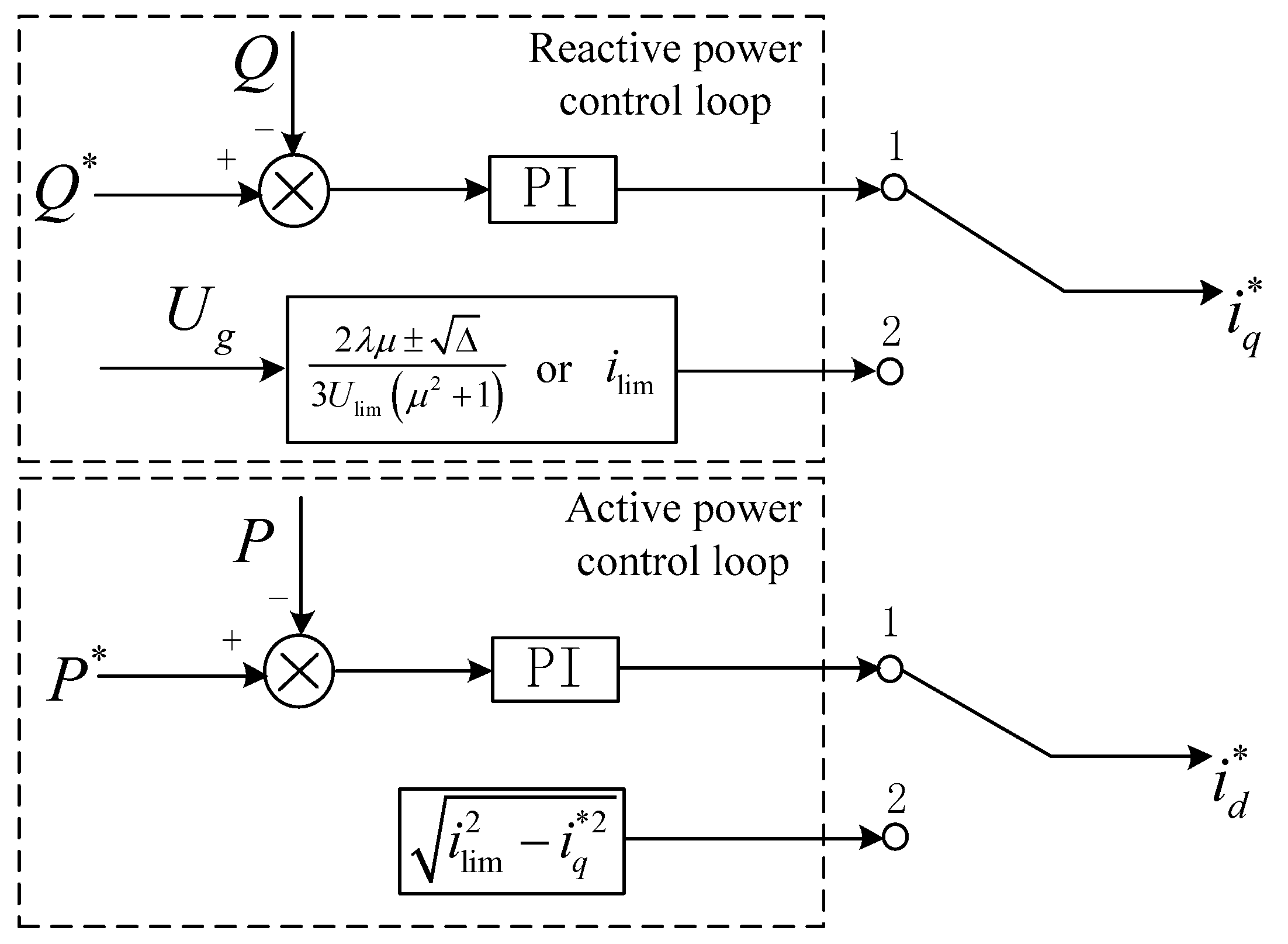
Based on the solution of the controllable operation region, the proposed control principle in this study is as follows. Under normal conditions, the reference value of the inner loop current of the VSC-HVDC system is calculated by the outer active and reactive power loops. During the grid fault, the reactive power reference value of the VSC inverter is obtained according to Equation (20). Thus, the inner loop current reference is obtained using Equation (24). Then, the inner loop current reference is reset according to the calculation result by disconnecting the outer loop of the VSC inverter controller. The control block diagram of the proposed method is shown in
Figure 5.
5. Simulation Study
A simulation model of the hybrid dual-infeed HVDC system was established in PSCAD/EMTDC to verify the validity of the commutation failure suppression method (
Figure 1). The sending-end grids were represented by
S1 and
S3, which were modeled with synchronous generators models and static loads to investigate the frequency characteristic. The receiving-end grids
S2 and
S4 were modeled with the voltage sources and series impedance for the sake of simplicity, and the SCR of the receiving-end grid was 2.5.
The CIGRE benchmark HVDC system was used in this paper and the LCC-HVDC system parameters were as follows: the rated power
Plcc was 1000 MW, the rated DC voltage was 500 kV, the rated current was 2 kA, the inverter side converter bus rated voltage was 230 kV, the transformer ratio was
k = 230/209.23, the transformer short-circuit impedance percentage was
XT% = 18%, the inverter rated extinction angle
γ was 15°, and the trigger lead angle
β was 38.3° [
22].
Three-phase, two-level bridges based on the IGBT power devices were adopted in the simulation study and the VSC-HVDC system parameters were as follows: the rated power was Pvsc = 500 MW, the rated DC voltage was 500 kV, and the inverter side converter bus rated voltage was 230 kV. The maximum current of the converter was generally selected as 1.5 times the rated value. The rectifier station adopted constant DC voltage control and constant reactive power control, and the inverter station adopted the constant active and reactive power controls. The converter station was in unit power factor running status during normal operation. The base capacity was 1000 MVA, and the base voltage was 230 kV.
The maximum allowable voltage amplitude of the commutated bus Umax was set as 1.0 p.u. According to Equation (7) and the parameters of the LCC-HVDC system, the critical commutation voltage Ulim could be calculated as 0.88 p.u. According to Equation (3), the active and reactive power outputs by the LCC-HVDC were 0.72 p.u. and −0.16 p.u. under the critical commutation voltage, respectively, whereas the active and reactive power outputs by the LCC-HVDC inverter were 1.0 p.u. and 0 p.u. under the maximum allowable voltage, respectively. The unit regulating power of the sending-end grid KS was set as 1200 MW/Hz and the operation error of primary frequency regulation as 0.3 Hz. According to Equation (19), the transmitted active power Pvsc of the VSC-HVDC system should have been larger than 0.42 p.u. and the corresponding maximum reactive power Qvscmax was 0.509 p.u. According to Equation (23), the critical voltage at fault point Uglim of the VSC-HVDC could be obtained as 0.765 p.u.
5.1. Validation of Control Effectiveness
The three-phase short-circuit fault occurred at the
k point on the receiving-end grid. The fault occurred at the instant of 3 s, and the voltage amplitude at the fault point
Ug decreased to 0.80 p.u. By substituting the fault voltage and critical commutation voltage into Equations (12), (16) and (19), the controllable operation region could be obtained.
Figure 6 shows the simulated controllable operation region of the hybrid dual-infeed HVDC system.
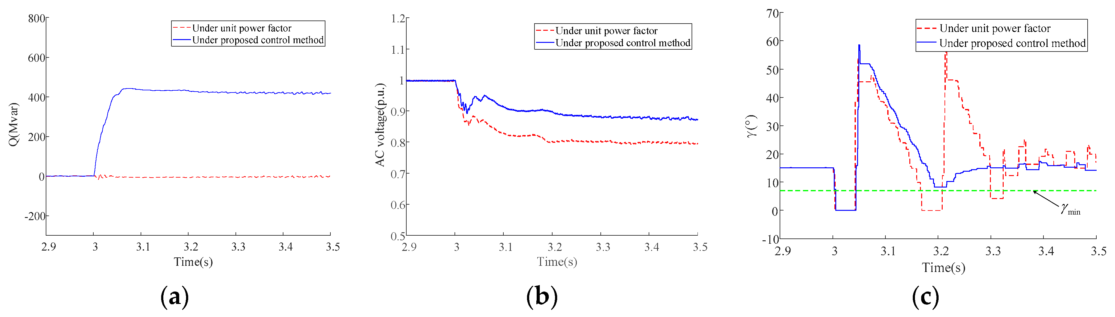
According to Equation (20), the reactive power reference value of the VSC inverter could be calculated as 0.43 p.u. Based on the control block diagram shown in
Figure 6, the inner loop current control reference of the VSC-HVDC inverter was switched to verify the effect of the commutation failure suppression method.
Figure 7 shows the simulated reactive power of the VSC inverter, commutated bus voltage of the LCC-HVDC, and extinction angle of the LCC-HVDC inverter. Without the switching control method, the reactive power reference of the VSC inverter maintained a constant value after the grid fault, and the commutated bus voltage amplitude decreased to 0.807 p.u. Commutation failure occurred three times at the LCC-HVDC inverter after the grid fault. Under the control method of this study, the VSC inverter delivered 430 Mvar reactive power after the grid fault, and the commutated bus voltage amplitude could be maintained at approximately 0.88 p.u. The commutation failure of the LCC-HVDC inverter occurred only at the instant of grid fault, which indicates that continuous commutation failure can be avoided by the proposed method.
5.2. Validation of Controlled Operation Region
The power operation points
A,
, and
were selected as the control reference values to validate the controllable operation region, as shown in
Figure 8. The active power and reactive power reference values of power operation point
A,
, and
were (0.5 p.u., 0.43 p.u.), (0.5 p.u., 0.51 p.u.) and (0.56 p.u., 0.43 p.u.), respectively.
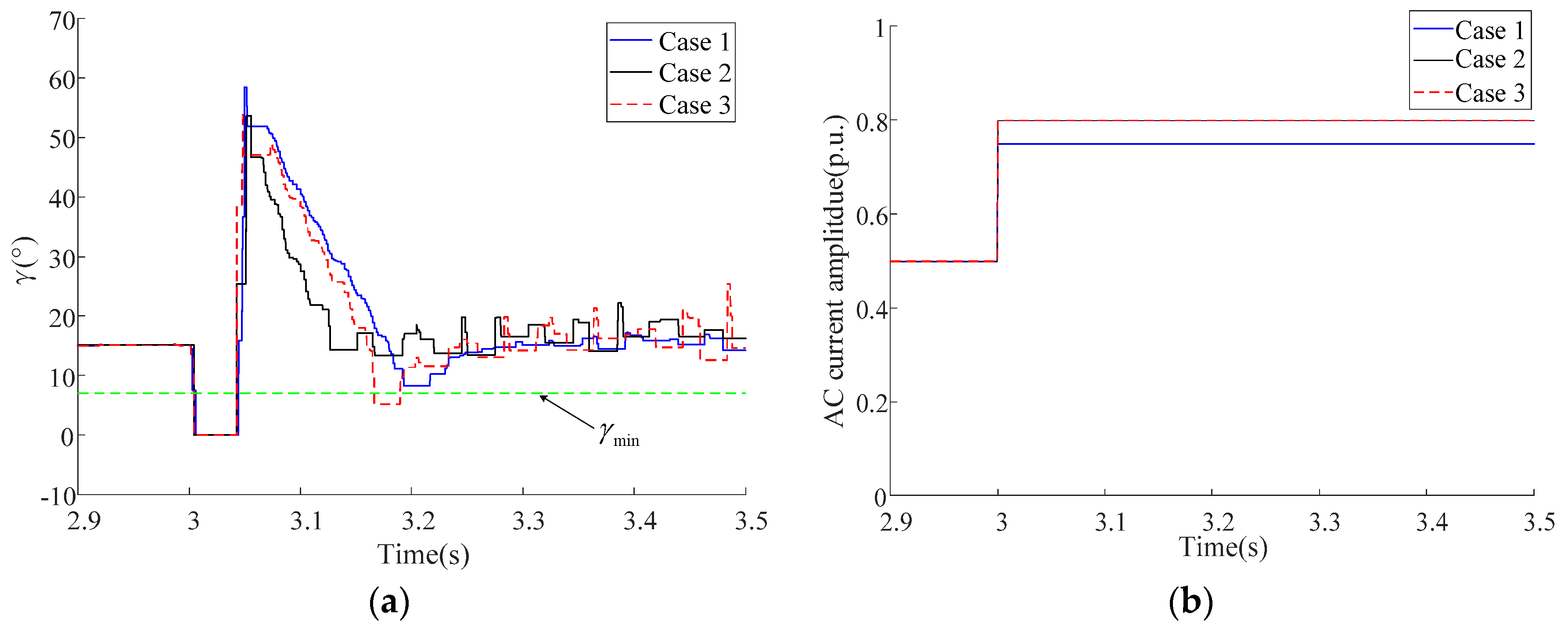
Figure 9 shows the simulated waveforms of the LCC-HVDC inverter extinction angle and AC current of VSC inverter under different operation points, where cases 1–3 are obtained by the power operation points
A,
, and
, respectively. In case 1 and case 2, the commutation failure occurred only once at the instant of grid fault. However, in case 2, the commutation failure occurred twice during the grid fault. The extinction angle of the second commutation failure was 5.8°, which was less than the critical extinction angle. Although the power operation points
A and
had the same reactive power reference value, power operation point
was located outside of the control operation region, which still led to the extinction angle being less than the critical extinction angle. Meanwhile, the AC current of the VSC inverter in case 1 was equal to
ilim, which fulfills these three constraints. However, only the commutation voltage control constraint and frequency constraint could be fulfilled in case 2.
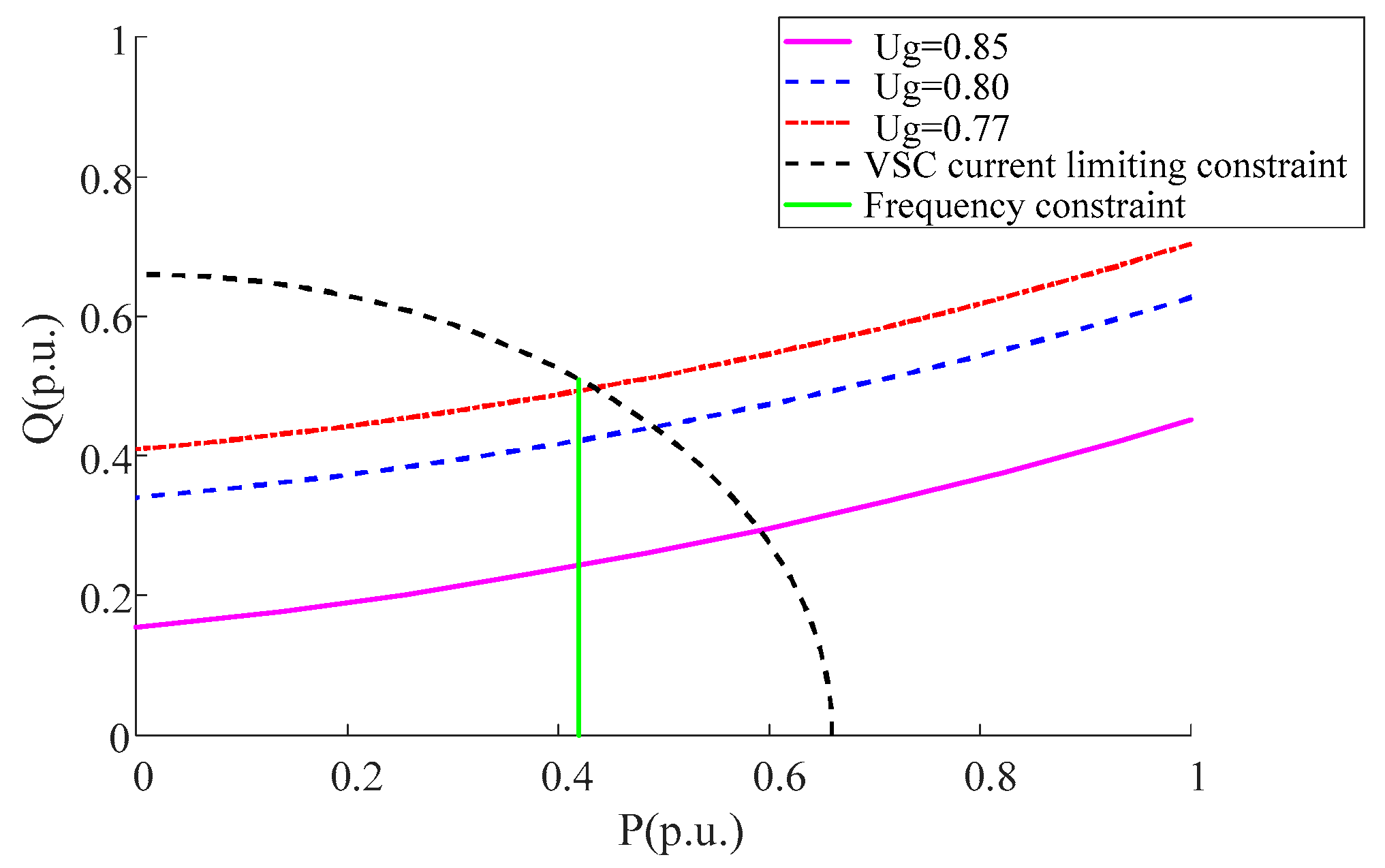
5.3. Variation of the Controllable Operation Range under Different Voltage Drops
According to Equation (23) and the HVDC system parameters, the critical voltage amplitude of fault point could be obtained as 0.762 p.u.
Figure 10 shows the controllable operation region under fault point voltage drops of 0.85, 0.8, and 0.77 p.u., and the corresponding reactive power operation points under different voltage drops, which were 0.29, 0.43, and 0.51 p.u., respectively. With the severity of the voltage drop, the VSC-HVDC needed to output more reactive power to fulfill the control requirement of critical commutation voltage to avoid the commutation failure of the LCC inverter. The controllable operation region of the hybrid dual-infeed HVDC system was gradually reduced. If the voltage amplitude is lower than
Uglim, the controllable operation region that can fulfill VCC, MCC and FC does not exists.
