Article

Short-Circuit Current Analysis for DFIG Wind Farm Considering the Action of a Crowbar

College of Energy and Electrical Engineering, Hohai University, Nanjing 211100, China
*
Author to whom correspondence should be addressed.
Energies 2018, 11(2), 425; https://doi.org/10.3390/en11020425
Submission received: 4 January 2018 / Revised: 1 February 2018 / Accepted: 7 February 2018 / Published: 12 February 2018
(This article belongs to the Section F: Electrical Engineering)

Abstract

:
With the increasing capacity of wind farms integrated into the power grid, the short-circuit current analysis for wind farms becomes more and more important. Since the wind turbine is usually integrated into the power grid via power electronic devices, the “crowbar” is installed in the wind turbine to protect the power electronic devices and to improve the fault ride through capability. The impact of the crowbar has to be considered during the short-circuit current analysis for the wind farm. In order to fully analyze the short-circuit current characteristics of a wind farm, the short-circuit currents for a doubly-fed induction generator (DFIG) wind turbine under symmetrical and asymmetrical faults considering the crowbar action characteristic are derived firstly. Then the action situation of the crowbar of a DFIG wind turbine is studied and the action area curve is obtained. Taking the crowbar action, or not, as the grouping criterion, wind turbines in the wind farm are divided into two groups, and the wind farm is aggregated into two equivalent wind turbines. Using the equivalent model, the short-circuit current of a wind farm can be calculated accurately. Finally, simulations are performed in MATLAB/Simulink which is the commercial math software produced by the MathWorks company in Natick, Massachusetts, the United States to verify the proposed short-circuit current calculation method for the DFIG wind farm.

Graphical Abstract

1. Introduction

With the increasing capacity of wind farms (WF) integrated into the power grid, the impact of WFs on the operation of power grid becomes more and more significant [1]. The short-circuit current of the WF under the system fault is quite different from that of the traditional power plant. The result of the fault analysis and the evaluation of protection action characteristics are affected by imprecise short-circuit current calculations, and it is of great significance to the electric design of the WF. Additionally, a “crowbar” is usually installed in the wind turbine (WT) with a doubly-fed induction generator (DFIG) to increase the fault ride-through capability by limiting the short-circuit current flowing through the power electronic devices under the system fault [2,3,4]. Hence, the effect of the crowbar has to be considered in the short-circuit current analysis for the power grid integrated with large-scale WFs.
Previously, a great deal of studies have been carried out to study the short-circuit current of WTs with DFIG. The impact factors on the short-circuit current was investigated in [5,6]. The effect of the low-voltage ride-through control strategy on the short-circuit current of WTs with DFIG was analyzed in [7,8]. The short-circuit current of the WT with DFIG protected by a crowbar was also studied in [9,10]. In [9], the sudden short-circuit process was regarded as a superimposition of the steady state operation and the transient state operation provoked by the reverse voltage, stator three-phase short-circuit current expression was obtained by carrying out the Laplace transformation and the inverse transformation to the state space equation. The studies mentioned above mainly focused on the short-circuit current of a single WT with DFIG. Moreover, because the WF usually consists of hundreds of WTs, the short-circuit current analysis of the WF is more efficient for the operation of the power grid, but there are fewer studies on it. A simple DFIG WF equivalent model, which can be used to quantify a WF’s short-circuit current contributions to the grid, was presented in [11], and the amplitude range of short-circuit current supplied by the WF was determined by analyzing the short circuit behavior of a DFIG with a crowbar. In [12], the WF was also equivalent to a single WT with DFIG to study the short-circuit current of the WF, where the effect of the crowbar was not considered. However, when the system fault happens, the actions of the crowbars in a WF are very complicated. For example, under a system fault, some of the crowbars would be triggered, while the others would not. In this condition, the detailed actions of the crowbars have to be discussed before the short-circuit current analysis for the WF.
In this paper, a method for the short-circuit current calculation for a DFIG WF under constant power factor control is proposed. The short-circuit current for the WT with DFIG under symmetrical and asymmetrical grid faults are presented firstly, where the action of Crowbar can be considered. The curve for action area of Crowbar is obtained, based on which the action of each crowbar of the WT in the WF can be decided using the terminal voltage and the input wind speed. Taking the crowbar action, or not, as the clustering criterion, the WTs in the WF are aggregated into two WTs with DFIG. Using the two-machine equivalent model, the short-circuit current of the WF is calculated. A WF consisting of 36 WTs which has considered the wake effect and is close to the actual WF is performed in MATLAB/Similink, which is the commercial math software produced by the MathWorks company in Natick, Massachusetts, the United States and approximates the real-time operating conditions. A comparison is made between the calculated and the simulated short-circuit current of the WF under symmetrical and asymmetrical fault, respectively. The effectiveness of the proposed short-circuit current calculation method for a DFIG WF is evaluated by the case studies.

2. Short-Circuit Current of WT with DFIG Considering the Action of Crowbar

2.1. Model of WT with DFIG Equipped with a Crowbar

The configuration of the WT with DFIG equipped with a crowbar under constant power factor control is shown in Figure 1.
Currently, the commercial WT with DFIG usually adopts the three-phase three-wire system where there is no zero-sequence component in the short-circuit current. Therefore, according to the instantaneous symmetrical component theory, the stator and rotor voltage, current and flux vectors can be decomposed into the corresponding positive and negative sequence vectors in the positive and reverse rotating synchronous coordinate systems. They are called positive and negative sequence vectors in the following part of this paper, respectively, and they can be written as:
f = f P + f N = f + P e j ω s t + f N e j ω s t ,
where f represents voltage, current or flux vector; the subscript “+” and “−” represent the forward and reverse synchronous rotating coordinate systems, respectively; the superscript P and N represent the positive and negative sequence components, respectively.
The positive and negative sequence models of WT with DFIG are given by:
{ U s , + P = R s I s , + P + d Ψ s , + P d t + j ω s Ψ s , + P U r , + P = R r I r , + P + d Ψ r , + P d t + j ( ω s ω r ) Ψ r , + P Ψ s , + P = L s I s , + P + L m I s , + P Ψ r , + P = L r I r , + P + L m I r , + P
{ U s , N = R s I s , N + d Ψ s , N d t j ω s Ψ s , N U r , N = R r I r , N + d Ψ r , N d t j ( ω s + ω r ) Ψ r , N Ψ s , N = L s I s , N + L m I r , N Ψ r , N = L r I r , N + L m I s , N
where U s , U r , I s , I r , Ψ s , Ψ r are the voltage, current, and flux of the stator and rotor, respectively; R s , R r , L s , L r are the resistance and inductance of the stator and rotor, respectively; L m is the mutual inductance of the generator; and ω s and ω r are the electrical angular velocities of the stator and rotor, respectively.
The negative sequence component is zero when the system is symmetrical.
When the power grid operates normally or the terminal voltage of WT with DFIG equipped with the crowbar drops slightly, the crowbar will not be triggered and the WT with DFIG is excited by the rotor side converter, which is the just like the WT with DFIG equipped without a crowbar. When the power grid fault happens and the terminal voltage drops deeply, the stator and rotor currents increase quickly with the decrease of the terminal voltage. Then, the crowbar is activated to prevent the converter from over-current shock and consumes the unbalanced energy in the WT after the system fault, which improves the fault ride through capability. Hence, the crowbar plays a very important role in the WT under the system fault, and it has to be included in the model of the WT with DFIG for the short-circuit current analysis.

2.2. Short-Circuit Current of WT with DFIG When the Crowbar Acts

If the terminal voltage falls deeply, the crowbar will be triggered. According to Equation (1), the stator and rotor currents can be decomposed into positive and negative sequence vectors in the positive and reverse rotating coordinate systems which can be written as:
{ I s = I s , + P   e j ω s t + I s , N e j ω s t I r = I r , + P   e j ω s t + I r , N e j ω s t
Therefore, the positive and negative sequence vectors of stator and rotor currents need to be calculated firstly. According to the positive and negative sequence flux in Equations (2) and (3), the relations between stator, rotor currents and fluxes can be obtained as follows:
{ I s , + P = L r L s L r L m 2 Ψ s , + P L m L s L r L m 2 Ψ r , + P I r , + P = L m L s L r L m 2 Ψ s , + P + L s L s L r L m 2 Ψ r , + P I s , N = L r L s L r L m 2 Ψ s , N L m L s L r L m 2 Ψ r , N I r , N = L m L s L r L m 2 Ψ s , N + L s L s L r L m 2 Ψ r , N
After the action of the crowbar, the rotor is shorted by the crowbar resistance, and the rotor side resistance is changed to R r = R r + R c b , where R c b is the crowbar resistance. According to Equations (2), (3), and (5), and neglecting the stator resistance, the differential equations of stator and rotor flux can be written as:
{ d Ψ s , + P d t + j ω s Ψ s , + P = U s , + P d Ψ s , N d t j ω s Ψ s , N = U s , N d Ψ r , + P d t + ( L s R r L s L r L m 2 + j ( ω s ω r ) ) Ψ r , + P = L m R r Ψ s , + P L s L r L m 2 d Ψ r , N d t + ( L s R r L s L r L m 2 j ( ω s + ω r ) ) Ψ r , N = L m R r Ψ s , N L s L r L m 2
When the power grid operates under normal condition, the stator flux is constant and the stator voltage equals to 1 pu. The initial values of the positive and negative sequence components can be obtained as follows:
{ I s , + P ( 0 ) = I s ( 0 ) Ψ s , + P ( 0 ) = Ψ s ( 0 ) Ψ r , + P ( 0 ) = L r L m Ψ s , + P ( 0 ) L s L r L m 2 L m I s , + P ( 0 ) I r , + P ( 0 ) = L m L s L r L m 2 Ψ s , + P ( 0 ) + L s L s L r L m 2 Ψ r , + P ( 0 ) Ψ s , N ( 0 ) = 0 Ψ r , N ( 0 ) = 0
Substituting Equation (7) into Equations (6), the differential equations can be solved:
{ Ψ s , + P = U s , + P j ω s + ( U s j ω s U s , + P j ω s ) e ( j ω s t + t τ s ) Ψ s , N = U s , N j ω s + U s , N j ω s e ( j ω s t + t τ s ) Ψ r , + P = A 1 U s , + P j ω s + B 1 ( U s j ω s U s , + P j ω s ) e ( j ω s t + t τ s ) + C 1 e ( j ω s t + j ω r t + t τ r ) Ψ r , N = A 2 U s , N j ω s + B 2 U s , N j ω s e ( j ω s t + t τ s ) + C 2 e j ω s t + j ω r t t τ r ,
where τ s = ( L s L m 2 / L r ) / R s is the time constant of stator, τ r = ( L r L m 2 / L s ) / R r is the time constant of rotor, and A 1 = L m R r ( j ω s + j ω r + 1 / τ r ) ( L s L r L m 2 ) , B 1 = L m R r ( 1 / τ r 1 / τ s j ω r ) ( L s L r L m 2 ) , C 1 = Ψ r . + P ( 0 ) U r . + P ( 0 ) j ω s + j ω r + 1 / τ r A 1 U s , + P j ω s B 1 ( U s U s , + P ) j ω s , A 2 = L m R r ( 1 / τ r j ω s j ω r ) ( L s L r L m 2 ) e j ω s t , B 2 = L m R r ( 1 / τ r 1 / τ s j ω r ) ( L s L r L m 2 ) , and C 2 = A 2 U s , N j ω s B 2 U s , N j ω s .
When the crowbar is triggered, the stator and rotor currents of WT with DFIG can be obtained by Equations (4), (5), and (8). If the fault is symmetrical, the negative sequence component is zero. The stator and rotor currents can be converted into a three-phase stationary coordinate system through coordinate transformation.

2.3. Short-Circuit Current of WT with DFIG When Crowbar Does Not Act

If the terminal voltage falls slightly, the crowbar will not be triggered and the rotor voltage will not be zero. According to the stator flux in Equations (2) and (3), the positive and negative sequence vectors of stator current can be written as:
{ I s , + P = Ψ s , + P L s L m I r , + P L s I s , N = Ψ s , N L s L m I r , N L s .
As shown in Equation (9), the short-circuit current is mainly determined by the stator flux and rotor current.
Since the action of the crowbar has no effect on the stator flux, the stator flux can be written as in accordance with Equation (8):
{ Ψ s , + P = U s , + P j ω s + ( U s j ω s U s , + P j ω s ) e ( j ω s t + t τ s ) Ψ s , N = U s , N j ω s + U s , N j ω s e ( j ω s t + t τ s ) .
During the grid fault, the rotor side converter can keep track of the reference value very well if the controller’s closed-loop bandwidth is large enough. The response of the converter is very fast, hence, if the rotor side converter control strategy is constant power factor control, the rotor current can be approximated to the reference value [13]:
I r = I r , r e f .
According to Equations (4) and (9)–(11), the stator and rotor currents of WT with DFIG can be obtained when the crowbar is not triggered. If the fault is symmetrical, the negative sequence component is zero.

2.4. Influence of Crowbar on Short-Circuit Current of WT

Two simulation systems for WTs with DFIG equipped with and without a crowbar are built in MATLAB/Simulink which is the commercial math software produced by the MathWorks company in Natick, Massachusetts, the United States as shown in Figure 1, respectively. The parameters of the WT are listed in Table 1.
The crowbar resistance is 30 * R r . The wind speed flowing into the WT is 11 m/s. A system fault is applied at the terminal of the WF via a short resistance at t = 0, and the terminal voltage drops to 0.5 pu. The short-circuit currents of phase A of these two simulation systems are shown in Figure 2.
From Figure 2, it can be seen that the short-circuit current of the WT equipped with a crowbar is different from that of the WT without a crowbar. Since the terminal voltage drops deeply to 0.5 pu, with a crowbar, the converter can be prevented from over-current shock and the unbalanced energy can be consumed by the crowbar in the WT. However, without a crowbar, the converter may face over-current shock and the unbalanced energy will affect the power grid. Their impact currents are also listed in Table 2.
From Table 2, it can be seen that the difference of the impact current is larger than 10%, hence, the effect of the crowbar has to be considered in the short-circuit current analysis.

3. Short-Circuit Current of a DFIG WF Considering Crowbar Operation Characteristics

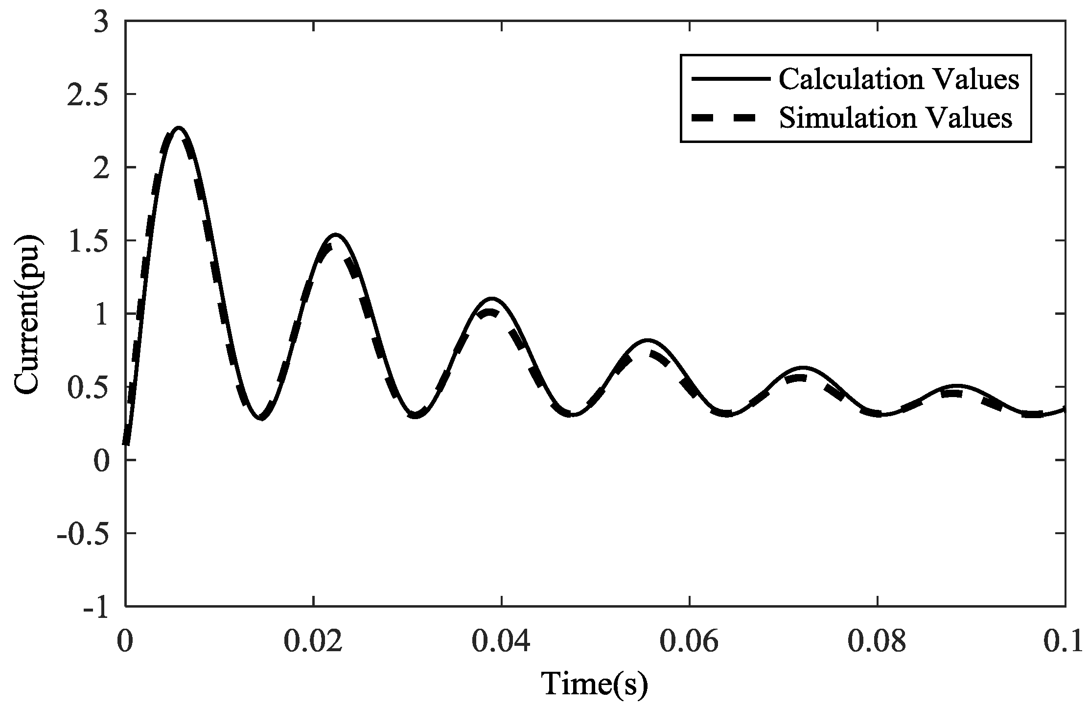
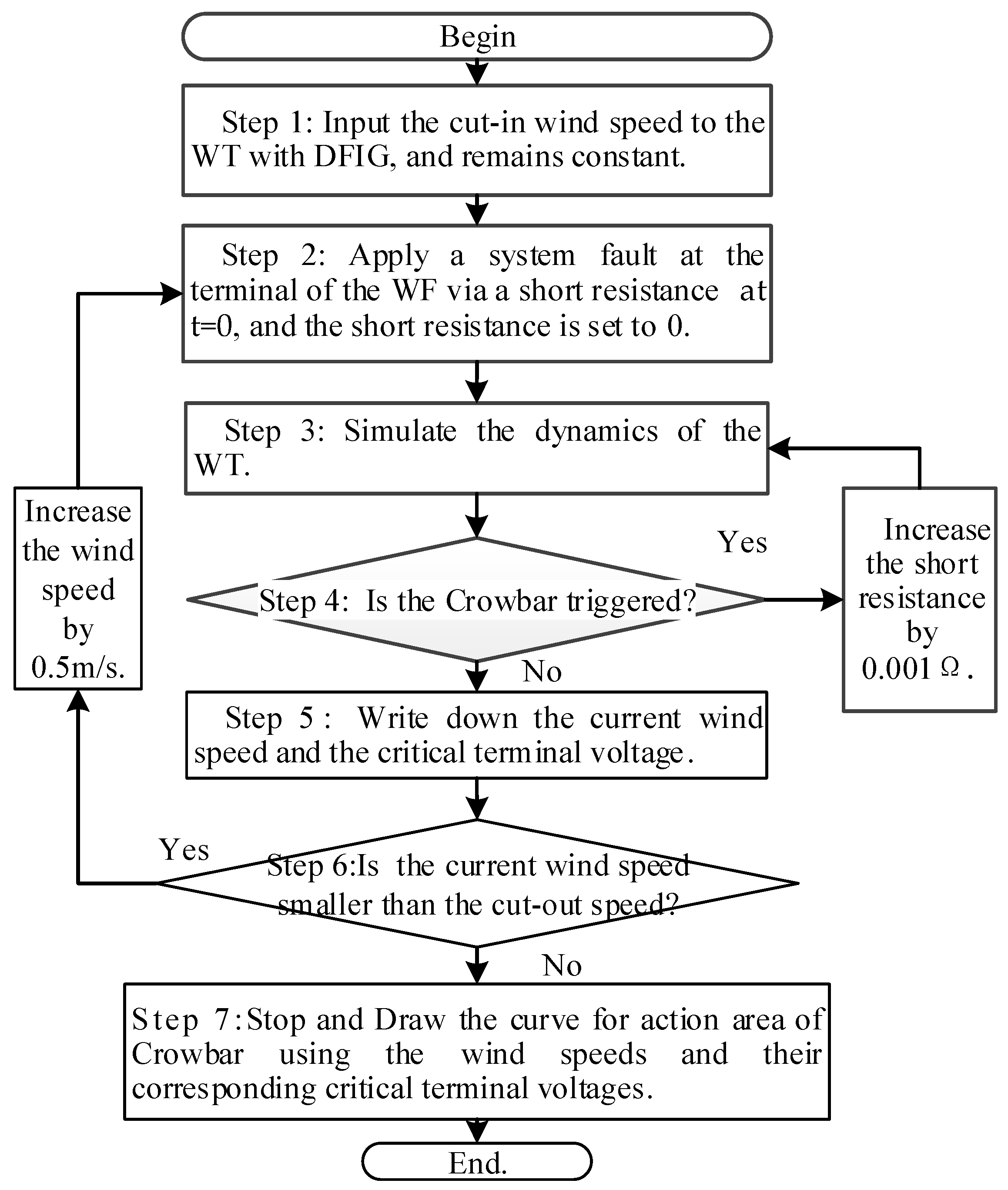
3.1. Curve for the Action Area of the Crowbar

In a WF, the time-lag effect and wake effect lead to the different input wind speeds flowing into each WT because of their different locations. Since the WT in the WF operates under different conditions, its crowbar would have different actions under the system fault. Especially when the system fault is not very severe, only part of the crowbars in the WF would be activated, while the others would not. At this scenario, if the WF is aggregated into one equivalent machine to calculate the short-circuit current, the errors will be significant.
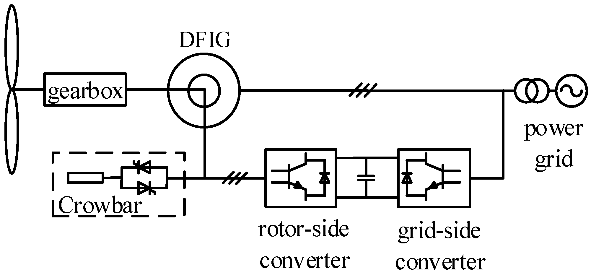
Therefore, it is necessary to decide the action condition of the crowbar in the WF before the calculation of the short-circuit current. The crowbar is triggered when the rotor current is greater than the current limitation. However, it is difficult to collect the instantaneous rotor current of each WT in the real WF. It has to be pointed out that the action of the crowbar has a strong relationship with the input wind speed and the terminal voltage drop [14].
The critical curve of the crowbar action for a single WT under different wind speeds and voltage drops is drawn by the following steps, as shown in Figure 3:
Step 1: Input the cut-in wind speed to the WT with DFIG, and it remains constant.
Step 2: Apply a system fault at the terminal of the WF via a short resistance at t = 0, and the short resistance is set to 0.
Step 3: Simulate the dynamics of the WT.
Step 4: Check the status of the crowbar. If the crowbar is triggered, increase the short resistance by 0.001 Ω and go to step 3; otherwise, go to step 5.
Step 5: Write down the current wind speed and the critical terminal voltage.
Step 6: If the current wind speed is smaller than the cut-out speed, increase the wind speed by 0.5 m/s and go to step 2; otherwise, go to step 7.
Step 7: Stop and draw the curve for the action area of the crowbar using the wind speeds and their corresponding critical terminal voltages.
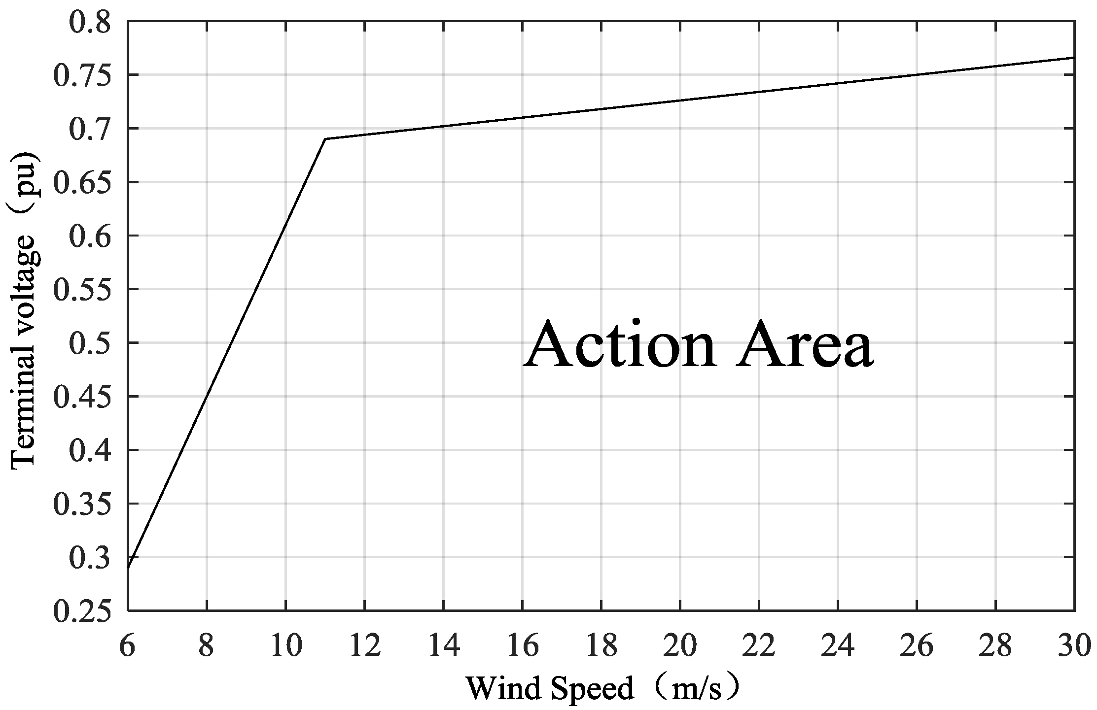
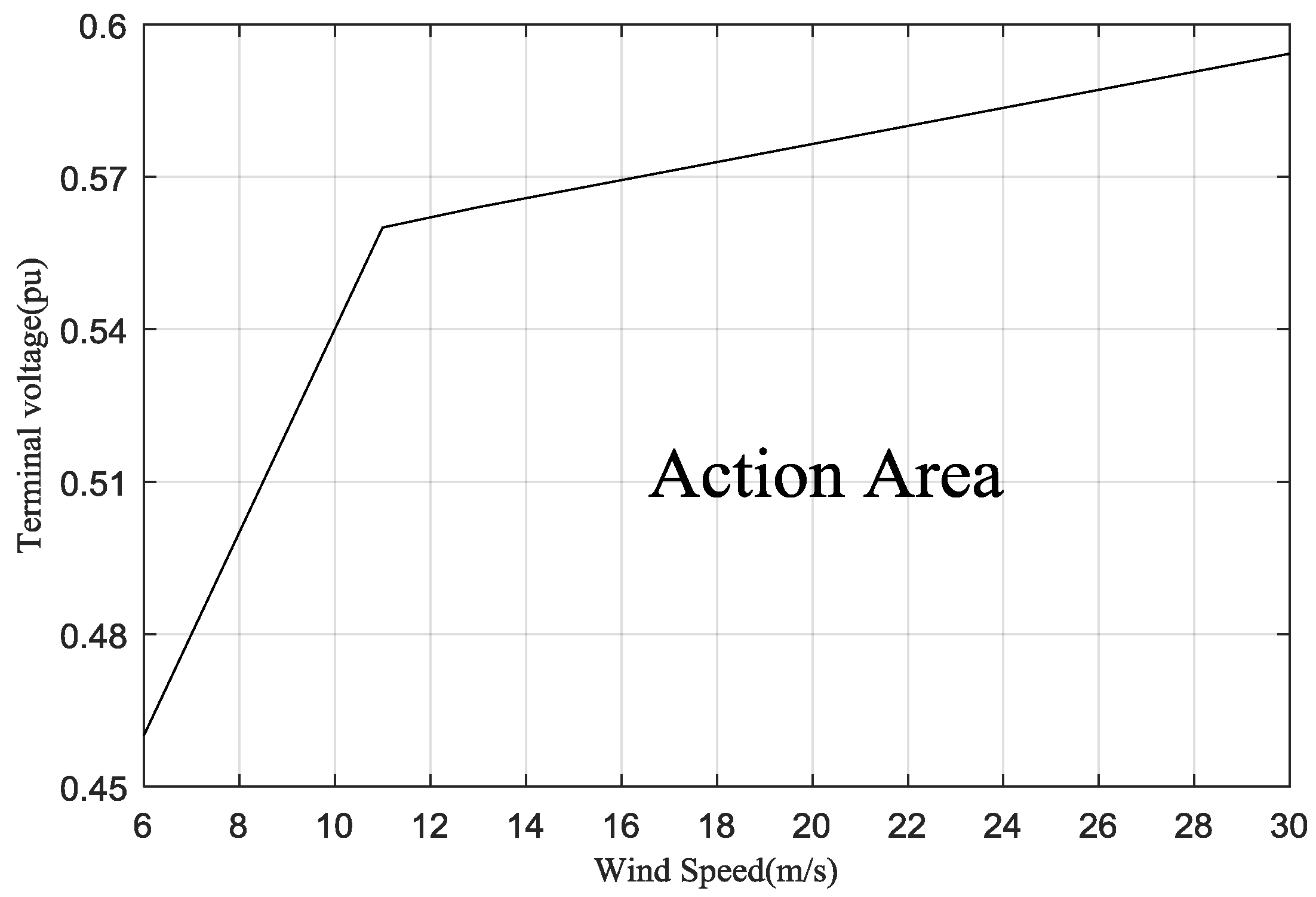
Following the above steps, the critical curve of the crowbar action for the WT with DFIG used in Section 2 is drawn and shown in Figure 4. As the rated wind speed of the WT is 11 m/s, the pitch angle controller of the WT will abandon the wind when the input wind speed exceeds the rated wind speed, which results the actual effective wind speed is equivalent to or slightly higher than 11 m/s. Therefore, the curve tends to be flat after the inflection point (11, 0.69).
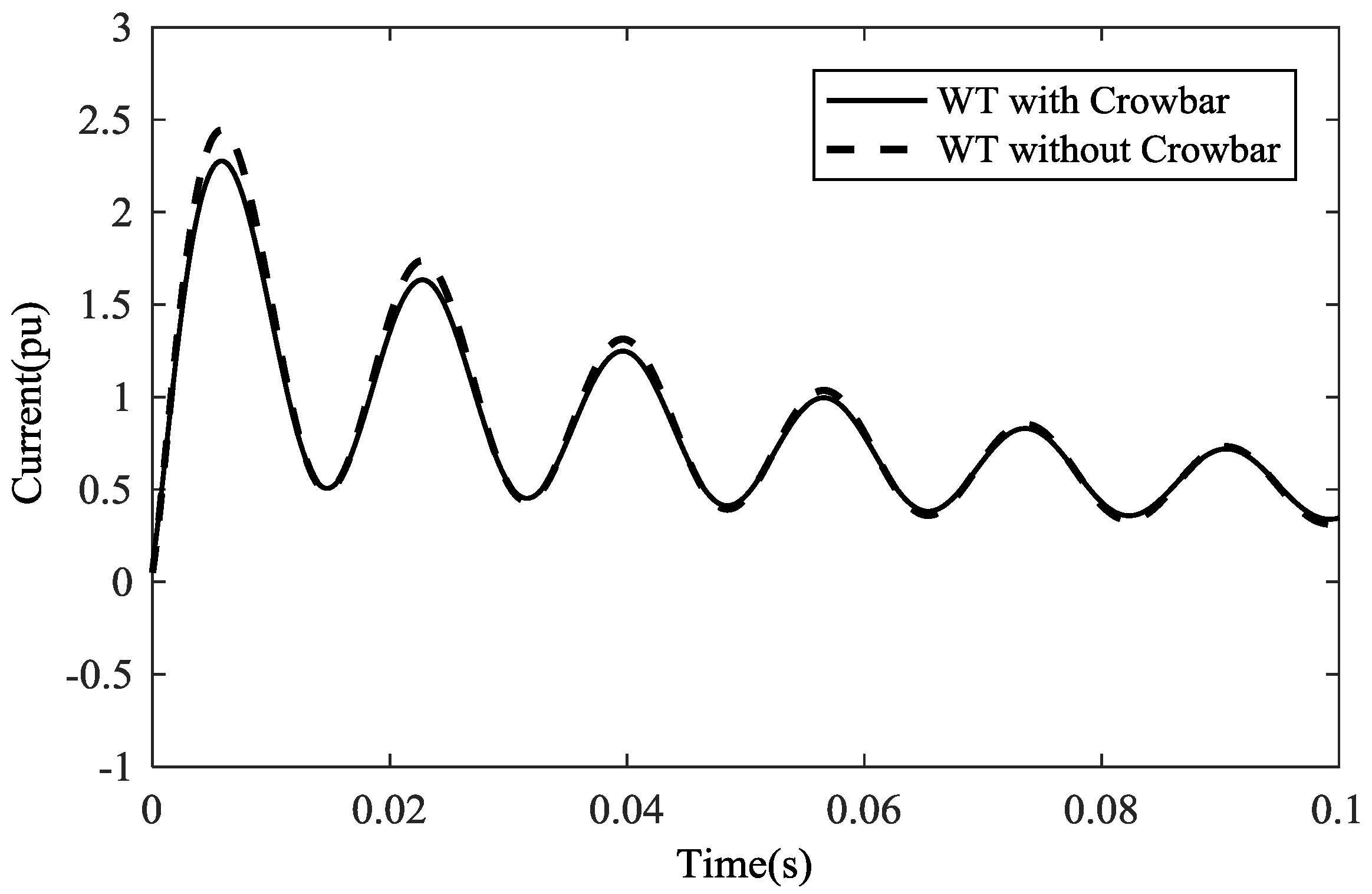
The input wind speed of each WT can be measured and collected since each WT is equipped with a wind speed meter in the real WF. The terminal voltage of each WT is also measured and sent to the control center of the WF. The input wind speed and the terminal voltage are used to look up the action area curve. The crowbar would be triggered when the operation point is below the critical line, otherwise it would not be triggered.
If there is more than one type of WT in the DFIG WF, the corresponding curve for the action area of each type of crowbar is required. However, the same type of WTs are used in the construction of WFs in general. Other types of WTs may be added during the later expansion processes, but not too many. Therefore, the calculation of the curves will not be too large if there are different kinds of WTs in the DFIG WF.

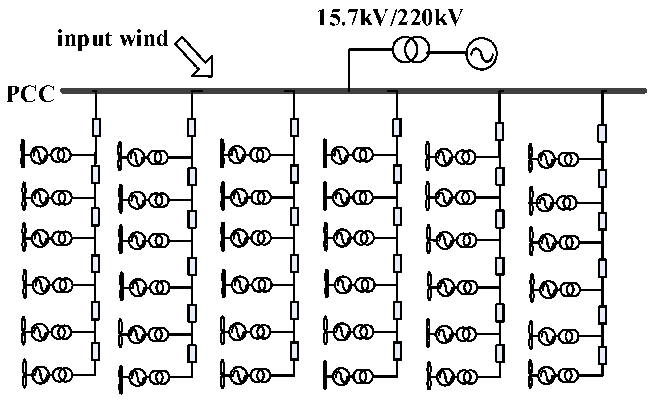
3.2. Short-Circuit Current Calculation of a DFIG WF

Firstly, the equivalent input wind speed is obtained by weighted aggregation of wind speed cubes. Secondly, the method of transforming the collection network in a WF proposed by [15] is applied to parallel the collection network, so as to achieve the aggregated equivalence of DFIGs at any location. Thirdly, the action of each crowbar in a DFIG WF is decided by the method proposed in 
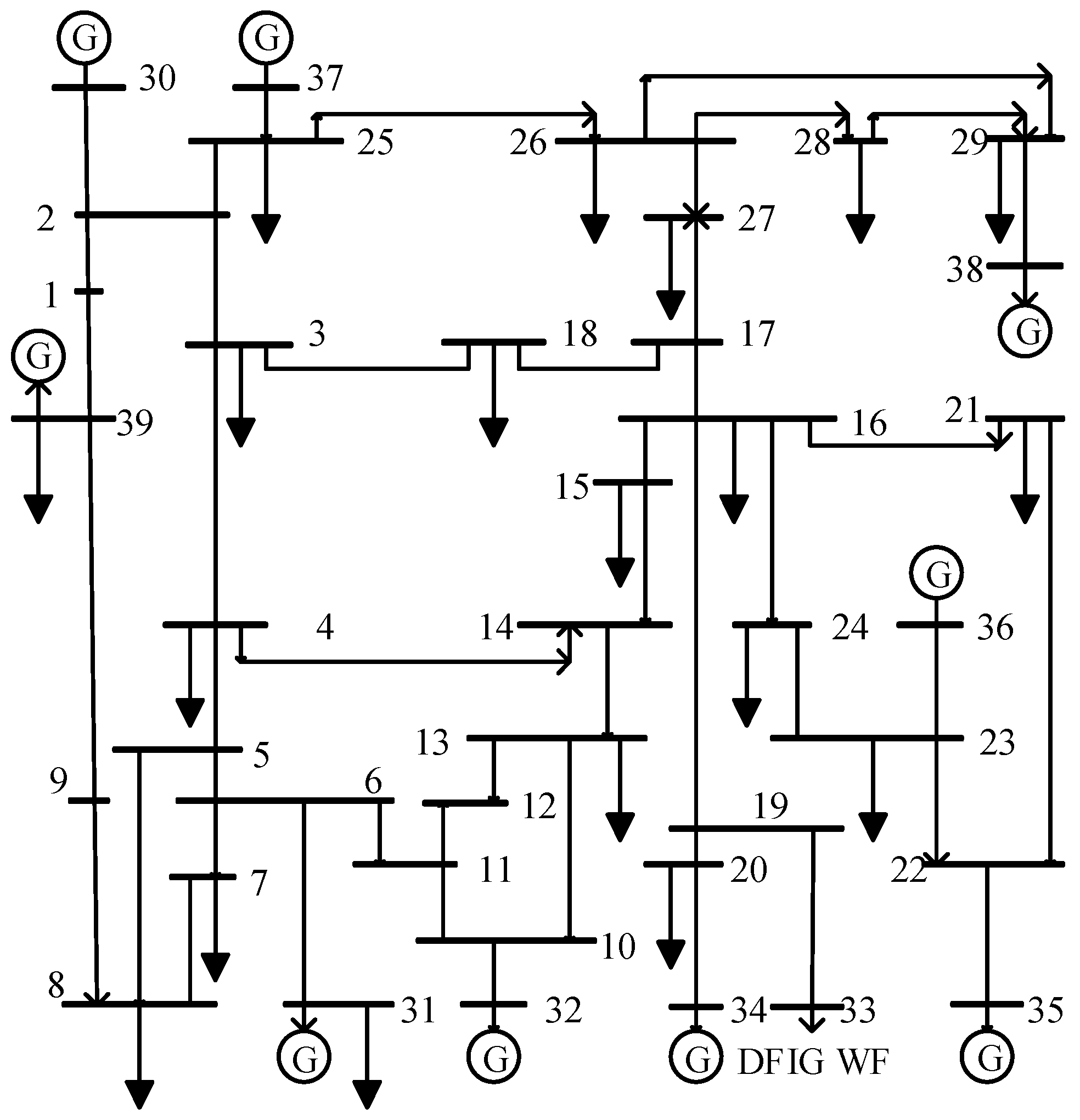
Section 3.1. Then, using the crowbar action as a clustering index, the DFIG WF is aggregated to a two-machine model, as shown in 
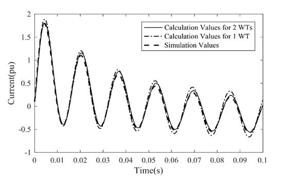
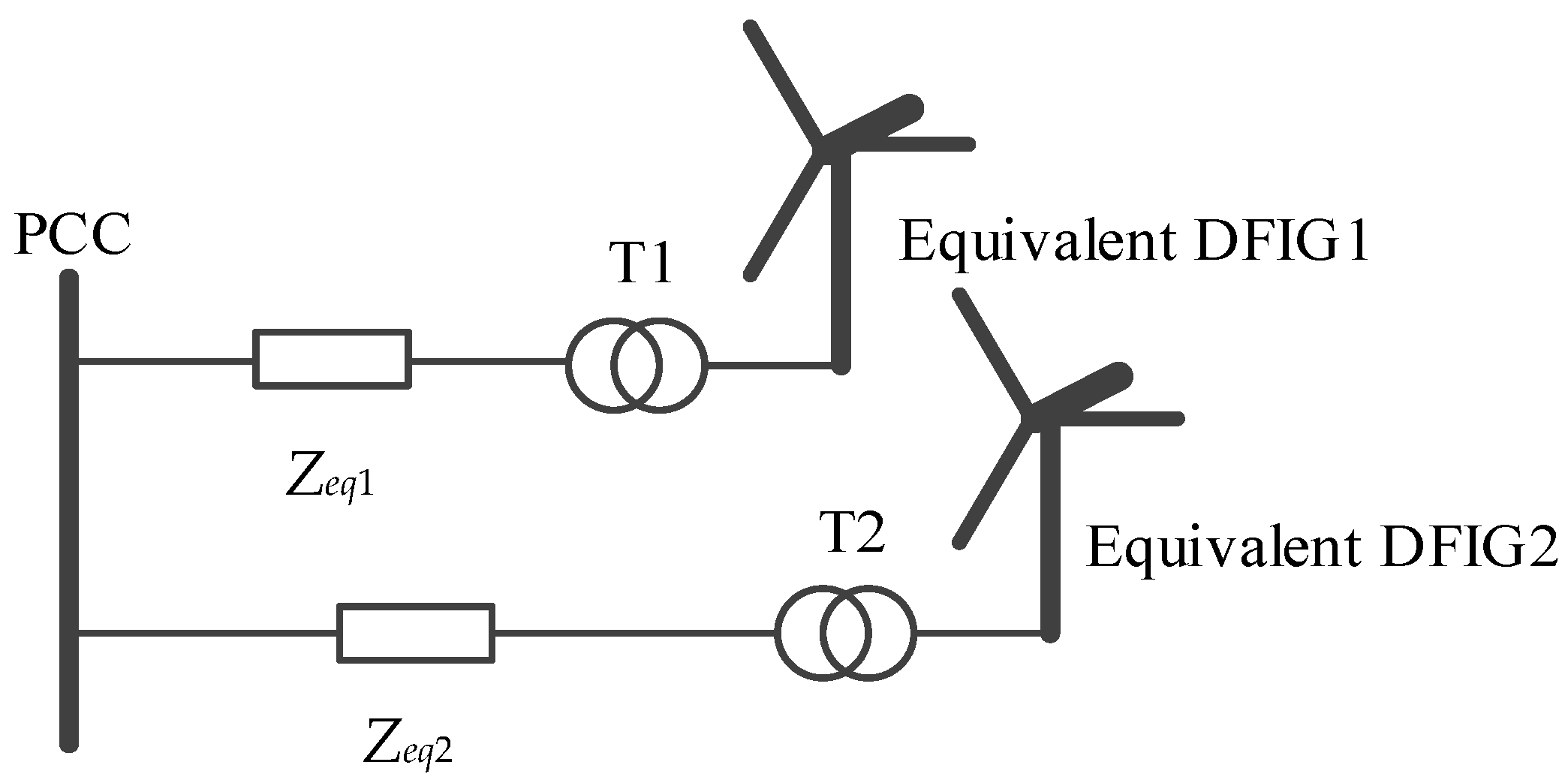
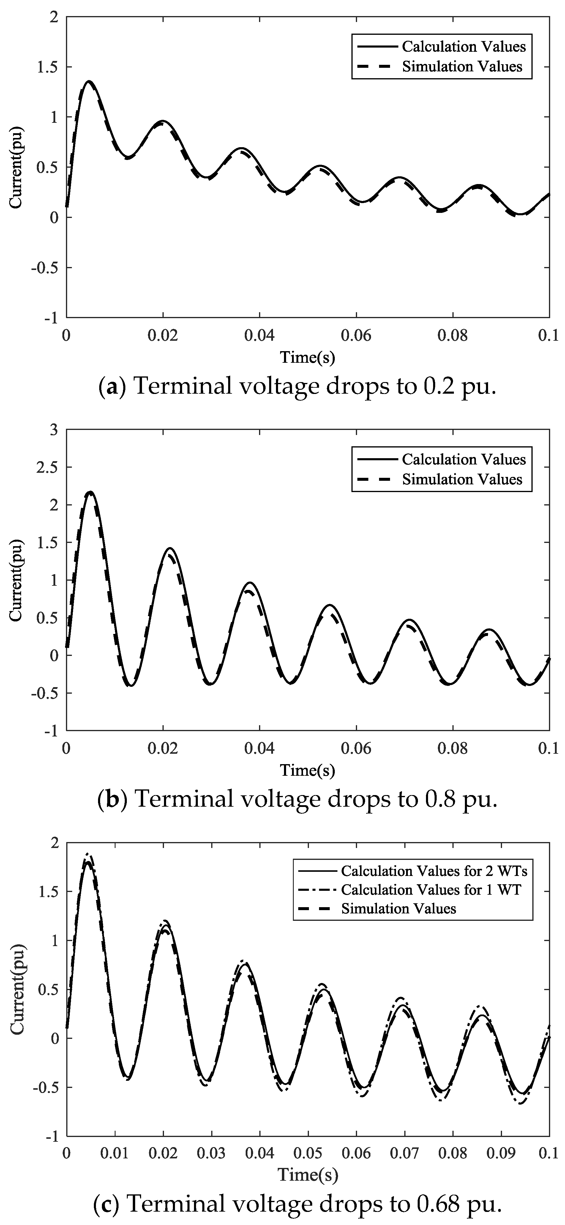
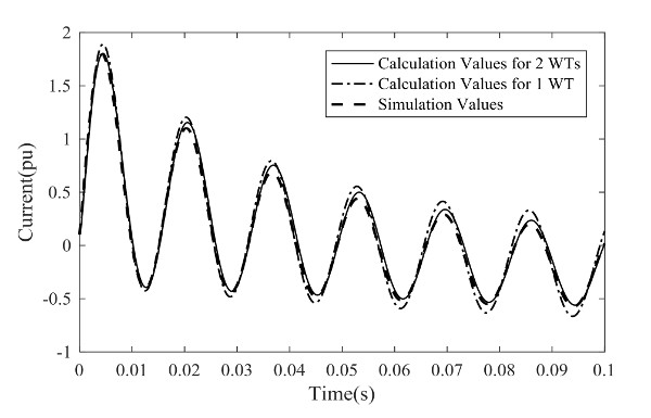
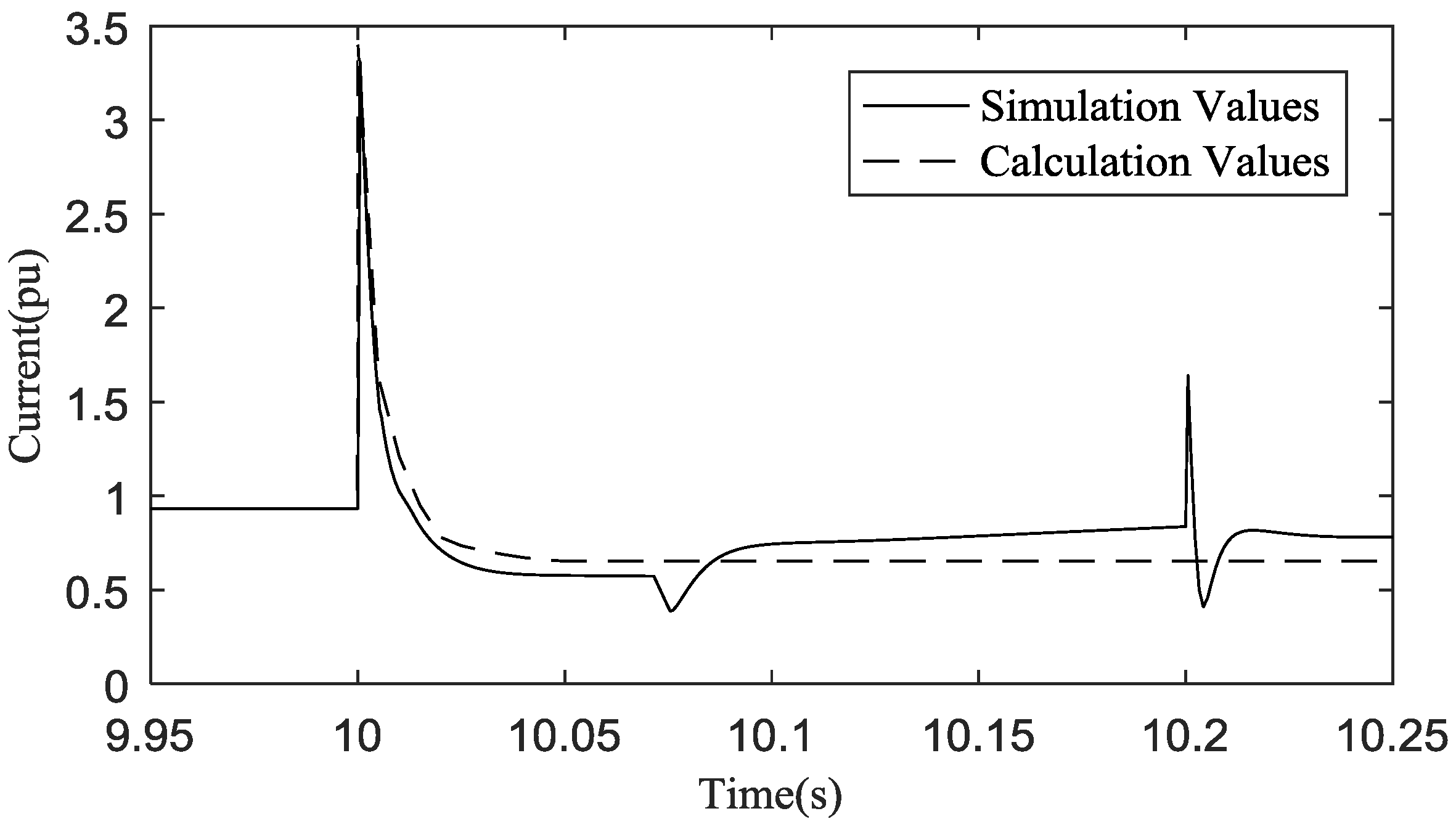
Figure 5, where one equivalent machine represents WTs whose crowbars are triggered and the other one represents the WTs whose crowbars are not triggered. Meanwhile, parameters of each equivalent machine are aggregated by the capacity weighted method. According to (4)–(5) and (8)–(11), the short-circuit currents of the two equivalent WTs with DFIG can finally be obtained, and the vector sum of them is the short-circuit current of the WF.

4. Simulation Examples

4.1. Crowbar Actions Simulation

A WF consisting of 36 WTs is built in MATLAB/Simulink which is the commercial math software produced by the MathWorks company in Natick, Massachusetts, the United States, as shown in Figure 6. The parameters of each WT with DFIG are listed in Table 1. Considering the wake effect, the wind speeds flowing into the WT in the WF are listed in Table 3.
Applying a system fault at the terminal of the DFIG WF via a short resistance at t = 0, the voltage drops to 0.68 pu. According to the simulation results, the actions of the crowbars in the WF are shown in Table 4. The crowbars that were triggered are represented by “+”, while the others are represented by “−”. From Table 4, it can be seen that 22 crowbars are triggered and the other 14 crowbars are not.
Using the curve for the action area of the crowbar, the crowbar action conditions for each WT in the WF can also be obtained and listed in Table 5. The result is that 22 crowbars are triggered and the other 14 crowbars are not, which is very close to that obtained from simulation. In Table 5, three crowbars in WTs have different actions comparing to those in Table 4. It has to be pointed out that the operation condition of these three WTs are very close to the critical curve. If the interval of the wind speed and terminal voltage is decreased further when the curve for the action area of the crowbar is produced, the accuracy of the decision can be improved.

4.2. Asymmetrical Fault Simulation

Applying a phase-phase fault between phase A and phase B at the terminal of the WF via different short resistances at t = 0, the voltage drops to 0.2 pu, 0.68 pu, and 0.80 pu, respectively.
When the terminal voltage drops to 0.2 pu, all the crowbars in the WF are triggered; while, when the terminal voltage drops to 0.8 pu, all the crowbars are not triggered. In these conditions, the WF can be equivalent to a single WT with crowbars and without crowbars, respectively, to calculate their short-circuit currents. The short-circuit currents are shown in Figure 7a,b, respectively. It can be seen that the calculation values of the short-circuit current is consistent with those of the simulations.
According to Table 5, only some of the crowbars are triggered when the terminal voltage drops to 0.68 pu. Therefore, the WF has to be aggregated to two equivalent WTs to calculate its short-circuit current. The short-circuit currents are shown in Figure 7c. In addition, the WF is also equivalent to a single WT to calculate its short-circuit current and show the difference between these two calculation methods. It can be seen that when the terminal voltage drops to 0.68 pu, the calculated short-circuit current of the WF which is equivalent to two WTs is closer to the simulation results than that of the WF, which is equivalent to a single WT.
Comparisons of the calculated impact currents and simulated impact currents under different voltage drops by an asymmetrical fault are shown in Table 6.
From Table 6, it can be seen that the WF can be equivalent to a single WT to calculate its short-circuit current when all the crowbars are triggered or not, since the error of impact current is very small. However, if only part of the crowbars are triggered, the error of impact current of the WF, which is equivalent to two WTs, is much smaller than that of the WF, which is equivalent to a single WT. Precise short-circuit current calculations will help the result of the fault analysis and the evaluation of the protection action characteristic.
Based on calculations and simulation results, it can be concluded that this DFIG WF needs to be equivalent to two WTs to calculate its short-circuit current when the terminal voltage dip is between 0.61 and 0.71. If not, it can be equivalent to a single WT.

4.3. Symmetrical Fault Simulation

Applying a three-phase fault at the terminal of the DFIG WF via a short resistance at t = 0, the voltage drops to 0.68 pu. The analysis process is the same as the asymmetrical fault, and the WF is equivalent to two WTs to calculate the short-circuit current. The comparison between the calculation values and simulation values of the short-circuit current of phase A is shown in Figure 8, and the impact currents of them are shown in Table 7.
From Figure 8 and Table 7, it can be seen that the calculation values of short-circuit current under a symmetrical fault are also consistent with those of the simulation results.

4.4. Fault Simulation in Digsilent

A DFIG WF consisting of 64 WTs connected to the IEEE 39 bus system at BUS33 is performed in Digsilent. The IEEE 39 bus system is shown in Figure 9. The parameters of each WT with DFIG are listed in Table 8. Considering the wake effect, the wind speeds flowing into the WT in the WF are listed in Table 9. The curve for action area of the crowbar is drawn in Figure 10.
Applying a phase-phase fault between phase A and phase B at the terminal of the DFIG WF via a short resistance at t = 10 s, the voltage drops to 0.55 pu. Using the curve for the action area of the crowbar in Figure 10, the result is that 66 crowbars are triggered and the other 15 crowbars are not, and the WF is equivalent to two WTs to calculate the short-circuit current. The comparison between the calculation values and simulation values of the short-circuit current is shown in Figure 11, and the impact currents of them is shown in Table 10.
From Figure 11 and Table 10, it can be seen that the calculation values of the short-circuit current are consistent with those of the simulation results.

5. Conclusions

A short-circuit current calculation method for the WF has been proposed in this paper, which has considered the action of a crowbar and is suitable under both symmetrical and asymmetrical grid faults. The simulation is conducted in MATLAB/Simulink, which is the commercial math software produced by the MathWorks company in Natick, Massachusetts, the United States and approximates the real-time operating conditions. Based on the short-circuit current analysis of the WT with and without the crowbar, the crowbar has a significant impact on the short-circuit current of the WT. The simulation results of a WF has demonstrated that only some of the crowbars were triggered under a certain grid fault. Hence, the action condition of the crowbar has been studied to obtain the curve for the action area of the crowbar, which is very useful to decide whether the crowbars are triggered. A two-machine equivalent model has been proposed to calculate the short-circuit current of the WF. The calculated short-circuit currents have been compared with those simulated, and they are close with each other. The proposed method is effective to calculate the short-circuit current of the DFIG WF even when there are different kinds of WTs in the WF, which is meaningful for further analysis for the influence of the DFIG WF on the fault analysis, protection action characteristics, and electric design of the WF. Analysis on an actual WF with different kinds of WTs is one of our future research directions.

Acknowledgments

This work was supported in part by National Science Foundation of China under grant no. 51422701. This article is funded by the National Science Foundation of China: 51422701 and China ‘111’ project of ‘Renewable Energy and Smart Grid’: B14022. The founding sponsors had an important role in the design of the study; in the collection, analyses, and interpretation of data; in the writing of the manuscript, and in the decision to publish the results.

Author Contributions

Feng Wu conceived and designed the experiments; Yan Hong Yuan performed the experiments; Feng Wu and Yan Hong Yuan analyzed the data; Feng Wu contributed analysis tools; Yan Hong Yuan and Feng Wu wrote the paper.

Conflicts of Interest

The authors declare no conflict of interest.

References

  1. Sun, S.; Liu, F.; Xue, S.; Zeng, F. Review on wind power development in China: Current situation and improvement strategies to realize future development. Renew. Sustain. Energy Rev. 2015, 45, 589–599. [Google Scholar] [CrossRef]
  2. Gao, F.; Xue, A.C.; Li, P.; Yan, Y.T.; Yang, Y. Research on the improvement of LVRT ability of an actual DFIG-type wind farm with Crowbar and SVG. In Proceedings of the International Conference on Renewable Power Generation IET, London, UK, 21–23 September 2016. [Google Scholar]
  3. Lopez, J.; Gubia, E.; Olea, E.; Ruiz, J.; Marroyo, L. Ride Through of Wind Turbines with Doubly Fed Induction Generator Under Symmetrical Voltage Dips. IEEE Trans. Ind. Electron. 2009, 56, 4246–4254. [Google Scholar] [CrossRef]
  4. Wang, S.Y.; Yu, D.R.; Foley, A.; Zhu, L.Z.; Li, K.; Yu, J.L. Flexible fault ride through strategy for wind farm clusters in power systems with high wind power penetration. Energy Convers. Manag. 2015, 93, 239–248. [Google Scholar] [CrossRef]
  5. Rahim, M.; Parniani, M. Grid-fault ride-through analysis and control of wind turbines with doubly fed induction generators. Electr. Power Syst. Res. 2010, 80, 184–195. [Google Scholar] [CrossRef]
  6. EI-Naggar, A.; Erlich, I. Fault Current Contribution Analysis of Doubly Fed Induction Generator-Based Wind Turbines. IEEE Trans. Energy Convers. 2015, 30, 874–882. [Google Scholar] [CrossRef]
  7. Yin, J.; Bi, T.; Xue, A.; Yang, Q. Study on short-circuit current and fault analysis method of hybrid wind farm with low voltage ride-through control strategy. Trans. China Electrotech. Soc. 2015, 39, 60–62. [Google Scholar]
  8. Bi, T.S.; Liu, S.M.; Xue, A.C.; Yang, Q.X. Fault analysis of doubly fed induction generator wind turbines with low-voltage ride-through capability. Power Syst. Prot. Control 2013, 41, 26–31. [Google Scholar]
  9. Zhang, J.H.; Chen, X.Y.; Wang, B.; Wang, P.; Liu, H.M. Three-phase short circuit analysis of DFIG-based wind generation and the crowbar biggest resistance setting. In Proceedings of the International Conference on Sustainable Power Generation and Supply, Nanjing, China, 6–7 April 2009. [Google Scholar]
  10. Wen, G.; Chen, Y.; Zhong, Z.; Kang, Y. Dynamic voltage and current assignment strategies of nine-switch-converter-based DFIG wind power system for low-voltage ride-through (LVRT) under symmetrical grid voltage dip. IEEE Trans. Ind. Appl. 2016, 52, 3422–3434. [Google Scholar] [CrossRef]
  11. Cui, Y.; Yan, G.G.; Jiang, D.W.; Mu, G.; Zhou, Z.Q.; Wang, X.B.; Li, Q. DFIG-based wind farm equivalent model for power system short circuit current calculation. In Proceedings of the International Conference on Sustainable Power Generation and Supply, Nanjing, China, 6–7 April 2009. [Google Scholar]
  12. Wessels, C.; Gebhardt, F.; Fuchs, F.W. Fault ride-through of a DFIG wind turbine using a dynamic voltage restorer during symmetrical and asymmetrical grid faults. IEEE Trans. Power Electron. 2011, 26, 807–815. [Google Scholar] [CrossRef]
  13. Harnefors, L.; Nee, H.P. Model-based current control of AC machines using the internal model control method. IEEE Trans. Ind. Appl. 1995, 34, 133–141. [Google Scholar] [CrossRef]
  14. Gao, Y.; Jin, Y.; Ju, P.; Zhou, Q. Dynamic equivalence of wind farm composed of double fed induction generators considering operation characteristic of crowbar. Power Syst. Technol. 2015, 29, 1427–1436. [Google Scholar]
  15. Jin, Y.Q.; Huang, Y.; Ju, P.; Pan, X.P. Collector network transformation methods for wind farm aggregated modeling. Power Syst. Prot. Control 2012, 40, 34–41. [Google Scholar]
Figure 1. Configuration of wind turbine (WT) with doubly-fed induction generator (DFIG) equipped with a crowbar.
Energies 11 00425 g001
Figure 2. Short-circuit currents of WTs equipped with a crowbar and without a crowbar.
Energies 11 00425 g002
Figure 3. Flowchart drawing curve for the action area of the crowbar.
Energies 11 00425 g003
Figure 4. Curve for action area of the crowbar.
Energies 11 00425 g004
Figure 5. Equivalent model of DFIG WF (wind farm).
Energies 11 00425 g005
Figure 6. Configuration of the DFIG WF.
Energies 11 00425 g006
Figure 7. Comparison of the short-circuit current calculation values and simulation values for a phase-phase (a and b) fault.
Energies 11 00425 g007
Figure 8. Comparison of the short-circuit current calculation values and simulation values for a three-phase fault.
Energies 11 00425 g008
Figure 9. IEEE 39 bus system.
Energies 11 00425 g009
Figure 10. Curve for action area of the crowbar.
Energies 11 00425 g010
Figure 11. Comparison of the short-circuit current calculation values and simulation values for a phase-phase (a and b) fault.
Energies 11 00425 g011
Table 1. Parameters of wind turbine (WT) with doubly-fed induction generator (DFIG).
ParametersValues
rated power/MW1.5
rated voltage/V575
system frequency/HZ60
stator resistance/p.u.0.023
stator inductance/p.u.0.18
rotor resistance/p.u.0.016
rotor inductance/p.u.0.16
mutual inductance/p.u.2.9
rotor speed/p.u.1.2
Table 2. Impact currents of WTs equipped with and without a crowbar.
WT with Crowbar/puWT without Crowbar/puAbsolute Error/puRelative Error/%
Impact current2.2682.5050.23710.4
Table 3. Wind speed distribution in the wind farm (WF).
NumberWind Speed (m/s)
Column 1Column 2Column 3Column 4Column 5Column 6
line 11211.811.611.411.211.0
line 211.811.611.411.211.010.8
line 311.611.411.211.010.810.6
line 411.411.211.010.810.610.4
line 511.211.010.810.610.410.2
line 611.010.810.610.410.210.0
Table 4. Simulation results of crowbar actions.
NumberCrowbar Actions
Column 1Column 2Column 3Column 4Column 5Column 6
line 1++++++
line 2++++++
line 3+++++
line 4+++
line 5++
line 6
Table 5. Comparison results of crowbar actions.
NumberCrowbar Actions
Column 1Column 2Column 3Column 4Column 5Column 6
line 1++++++
line 2+++++
line 3++++
line 4+++
line 5++
line 6+
Table 6. Comparison of the impact currents under different voltage drops by an asymmetrical fault.
Terminal Voltage/puImpact Current
Simulation Value/puCalculation Value/puAbsolute Error/puRelative Error/%
0.81.3541.3620.0080.591
0.22.3282.3410.0130.558
0.68 (2 WTs)1.7921.8040.0120.670
0.68 (1 WT)1.4181.8900.0985.469
Table 7. Comparison of the impact currents under symmetrical fault.
Simulation Value/puCalculation Value/puAbsolute Error/puRelative Error/%
Impact current2.3232.3400.0170.732
Table 8. Parameters of WT with DFIG.
ParametersValues
Rated power/MW2
Rated voltage/V575
System frequency/HZ60
Stator resistance/p.u.0.01
Stator inductance/p.u.0.1
Rotor resistance/p.u.0.01
Rotor inductance/p.u.0.1
Mutual inductance/p.u.3.5
Rotor speed/p.u.1.2
Table 9. Wind speed distribution in the WF.
NumberWind Speed (m/s)
Column 1Column 2Column 3Column 4Column 5Column 6Column 7Column 8
line 112.412.212.011.811.611.411.211.0
line 212.212.011.811.611.411.211.010.8
line 312.011.811.611.411.211.010.810.6
line 411.811.611.411.211.010.810.610.4
line 511.611.411.211.010.810.610.410.2
line 611.411.211.010.810.610.410.210.0
line 711.211.010.810.610.410.210.09.8
line 811.010.810.610.410.210.09.89.6
Table 10. Comparison of the impact currents under symmetrical fault.
Simulation Value/puCalculation Value/puAbsolute Error/puRelative Error/%
Impact current3.3083.4130.1053.174

