1. Introduction
Design and operation synergies of combined offshore wind and marine energy devices reduce the cost by increasing the renewable energy yield per square kilometer of ocean space. In the past, better progress has been seen in developing the substructures and devices for wind and wave energy systems independently from the offshore synopsis. Several substructures on fixed/floating offshore wind turbines and wave energy devices/converters (WEC) have been proposed and studied [
1,
2,
3]. The fusion of wave and wind energy has two clear aspects: (1) Merging the independent FOWT and WEC in a so-called “segregated” farm, (2) Combining the wave and wind energy structures in one unit so-called “hybrid” platform. The latter is the main focus of this paper. The implementation of the WEC system on the floating offshore wind turbine (FOWT) can be used for stabilization of the dynamic behavior of the complete hybrid system. The increased stability ensures more stable wind power generation. The hybrid platform is subjected to similar challenges by both FOWT and WEC, sharing same hostile severe offshore environmental conditions. Due to mechanical and hydrodynamic couplings between the floating bodies, the behavior of the FOWT would be changed by adding the WEC.
Borg et al. investigated a vertical axis wind turbine mounted on the Tri-Floater semi-submersible floating platform combined with a hypothetical WEC, represented by an additional degree of freedom in heave [
4]. The study includes the identification of optimal damping and stiffness parameters for maximum energy extraction and motion reduction. Taghipour and Moan studied the multiple WECs in the frequency domain by using a mode expansion method [
5]. The main objective is to assess the performance of the floating platform in absorbing the wave energy and its influence caused by the power absorption mechanism. Liao et al. studied the concept design of a WEC which is used as a motion suppression system of a FOWT platform to harvest additional energy [
6]. For simplicity, the two-dimensional mathematical model for a hydrodynamic feature of the coupled FOWT-WEC system is analyzed based on a linear potential flow theory. Karimirad and Kourosh carried out numerical simulations on the hybrid structure formed by combining a floating wind turbine supported by a spar-type substructure and a WEC inspired by Wavestar [
7]. The numerical scheme is based on the integrated/coupled aero-hydro-servo-elastic formulations in the time domain by choosing a proper power-take-off (PTO) system. The hydrodynamic interaction between the spar and the WEC is neglected in their study.
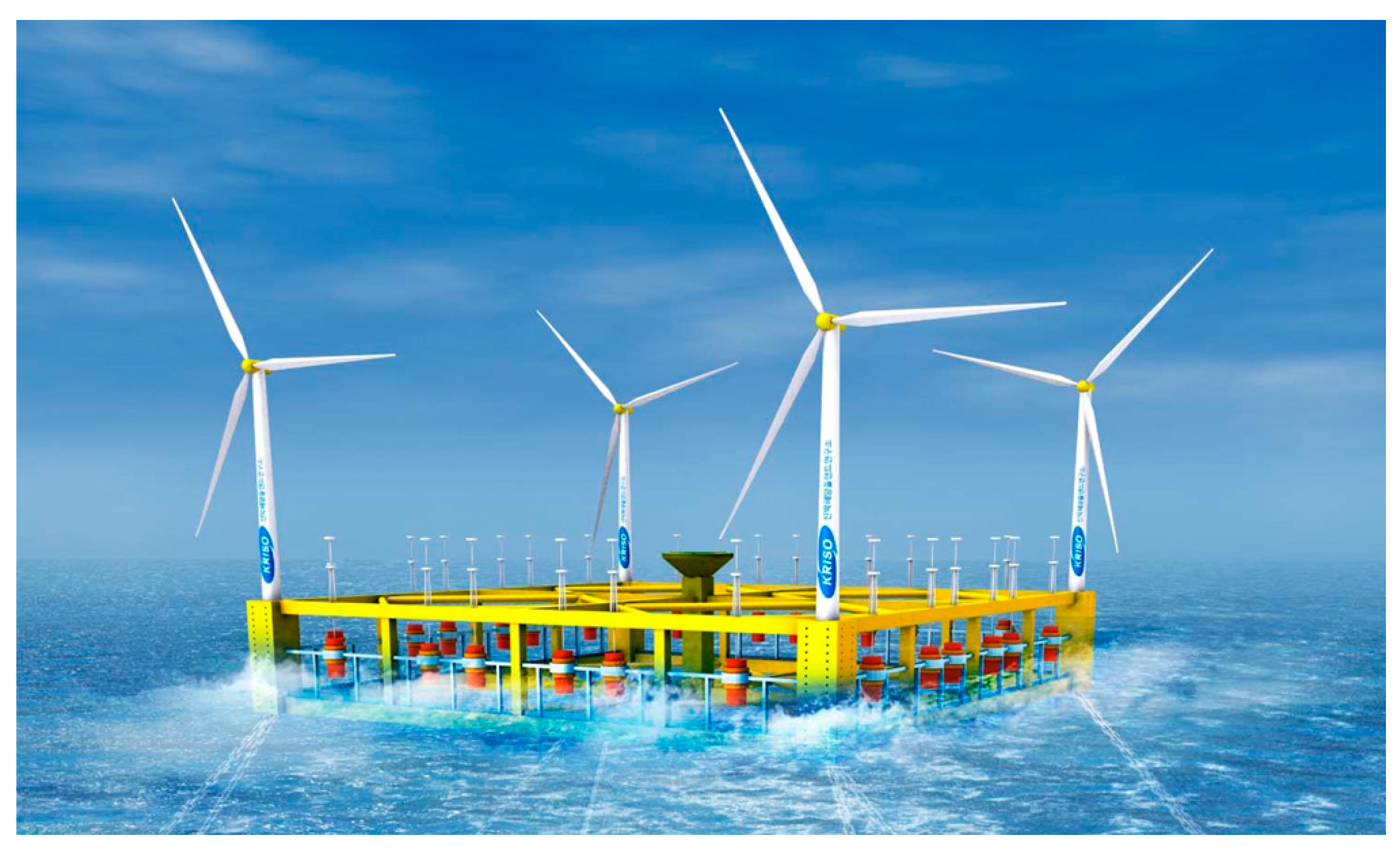
The above-mentioned works are based on a single FOWT with multiple WECs concepts. More recently, concepts with multiple FOWTs have drawn attention, e.g., W2-Power, Poseidon and 2Wave1wind. Limited progress in the theoretical design of these types of systems can be seen in the literature. Kim et al. designed a conceptual 10MW-class wave-offshore wind hybrid power generation system which has four wind turbines at each corner of the semi-submersible and 24 WECs along the side [
8]. Wake effects between the wind turbines made the size of the platform larger, and this has led to numerous challenges such as structural design and mooring design, etc. Lee et al. studied the dynamic response of the same hybrid platform and multiple WECs based on one-way coupling by considering the PTO damping as the static WECs on the platform to examine the effect of the WECs on the platform [
9].
In the present study, the performance analysis of the floating platform and the multiple WECs placed on the platform in the frequency domain has been carried out based on coupled hydrodynamic interaction. In addition, the PTO damping force raised by the relative heave motion between the platform and each WEC were considered. To assess the energy yield between the multiple WECs and the platform, the
q-factor is used for quantification.
Section 2 presents the details of the submerged platform specifications, WECs configuration and mooring line arrangements.
Section 3 includes the summary of the multi-body mathematical model.
Section 4 deals with numerical results and discussion. The evaluation of the interaction of the array of the multiple WECs is discussed using the
q-factor in
Section 5. Salient conclusions are presented in
Section 6.
3. Mathematical Model
To see the dynamic motion responses of the multiple WECs and the floating platform at the same time, a multi-body mathematical model was established. The floating platform was assumed to be a rigid body with six degrees of freedom. Multiple WECs were mathematically modeled as a damper with a PTO damping coefficient and attached to the platform. With this model, the vertical motion of the floating platform and the vertical motion of the WECs were assumed to be dynamically coupled. Surge, sway, and yaw modes were mathematically modeled considering the floating platform and the WECs moving as one single rigid body, and individual motions are not allowed because of the mechanical constraints. In the case of platform roll and pitch, the entire body cannot be modeled as one rigid body because the WECs were allowed to slide along the vertical guide shaft. For this reason, the mass moment of inertia of roll and pitch were estimated by summation of platform inertia and individual WEC inertia with respect to its own origin [
5]. The hydrodynamic coefficients, such as added mass, radiation damping, and wave exciting force, of the floating platform and each WEC were obtained by WAMIT, which is a potential-based 3D diffraction/radiation panel program [
11]. Since hydrodynamic interactions between the floating platform and the WECs or inter-WECs are very important to estimate the overall motion responses, WAMIT multi-body analysis was conducted, allowing independent vertical motions of the platform and the 24 WECs. With this assumption, a total of 30 equations of motion per frequency were established. The 30 degrees of freedom included six rigid modes for the platform plus 24 heave modes from the WECs. Because the platform vertical motions caused by heave, roll, and pitch modes was assumed to be coupled with the heave of the WECs, the added mass and radiation damping of the coupled heave responses between the platform and the WECs and between each WEC should also be computed. The coupled terms were obtained from the radiation potential by exciting each body one by one in each direction, while the other bodies were at MWL without any forced excitations. Through this multi-body analysis, coupled added mass and radiation damping can be established. Since wave exciting forces are calculated from the wave diffraction potential, all the bodies were assumed to be fixed and 30 degrees of freedom (DOFs) of wave exciting forces were obtained.
In this regard, the wind-wave hybrid platform can be regarded as a multi-DOFs system. Typically, the dynamical system consisting of many components has local nonlinearities due to its complexity and the multi-DOFs system with local nonlinearities is known to experience so-called “emergent modes”. In the system of complexity or multi-DOFs, such “emergent modes” can completely dominate the system behavior, so the overall system performance can be reduced. The subharmonic or chaotic motions of compliant offshore structures such as tethered floating platform and articulated mooring towers was identified and its magnitude was numerically estimated by Thomson et al. [
12]. Thomson and Elvey also showed how the subharmonic resonance can be designed-out by increasing the damping to a prescribed level, or by changing other system parameters [
13]. In this context, nonlinear mooring forces or nonlinear coupling effect between multiple bodies were not considered and the absence of those nonlinear effects may lead to underestimation of the response of the entire system. Studies pertaining to “emergent modes” are left out of the present scope.
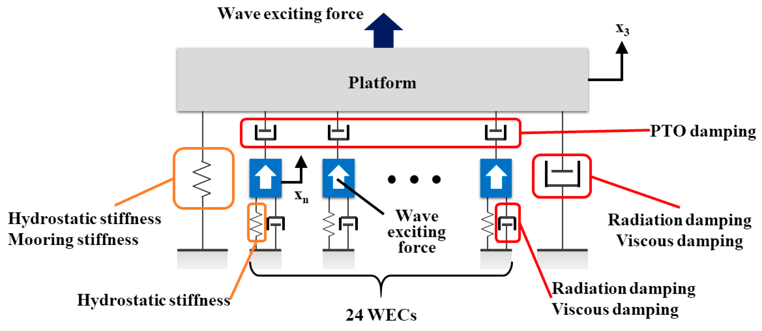
Figure 5 shows the schematic model of the multiple WECs placed on a floating platform. The hydrostatic stiffness and mooring stiffness are modeled as a spring, and the radiation damping and viscous damping are modeled as a damper. The PTO damper is placed in between the platform and the WEC.
The coupled equations of motion for the platform in heave, roll, and pitch modes are written in the form:
where subscript 1, 2, 3, 4, and 5 represent the surge, sway, heave, roll, and pitch of the platform, respectively. Subscript
indicates the heave of the
-th WEC (
k = 1, 2, …, 24 and
n =
k + 6).
is the platform mass or mass moment of inertia,
is the platform added mass coefficient,
is the radiation damping coefficient,
is the linearized viscous damping coefficient,
is the PTO damping coefficient,
and
are the distance from the platform origin to the center of the
-th WEC in the
x and
y directions, respectively, and
is the stiffness coefficient including the hydrostatic stiffness and the linearized mooring line stiffness. In general, a semi-submersible platform moored by catenary mooring lines can be excited by second-order difference-frequency wave load which can induce significant excursion in surge. However, the equations of motion in this study are mostly focused on the heave and coupled heave between the platform and WECs, so the nonlinear motion of the moored platform is neglected.
represents the wave exciting force or moment.
,
, and
are acceleration, velocity, and displacement of motion, respectively.
represents the vertical velocity of the platform at each position of the WEC, which can be calculated as
.
In Equation (1), the coupled terms between the platform heave and the heave of each WEC are considered. In Equations (2) and (3), the coupled terms with the heave of each WEC as well as the coupled terms between the platform surge and pitch or between the sway and roll are taken into account. PTO damping is a unique damping resource that arises from the WEC system. The PTO damper connections between the floating platform and WECs also induce additional force or moment terms represented by
,
, or
, which are proportional to the relative velocity between the platform and the WECs. In general, PTO damping is generated by the power conversion mechanism, and it is hard to define as a constant value. In this study, however,
was assumed to be constant (12,090 kg/s) regardless of the relative heave velocity between the platform and the WECs. This value is obtained from the previous optimization study by Cho and Choi [
14].
Since each WEC moves in heave only, the equation of motion of
-th WEC can be expressed similarly to Equation (1) as:
where subscript
represents the heave of each WEC, except that of the
-th WEC. Not only the coupled terms between platform heave and the heave of each WEC, but the coupled terms in between the WECs are considered.
Technically, WAMIT is not able to consider the viscous damping force because it is a potential-based radiation/diffraction solver. Therefore, the linearized viscous damping force was considered as an external damping, using the non-dimensional damping coefficient obtained from free decay experiments.
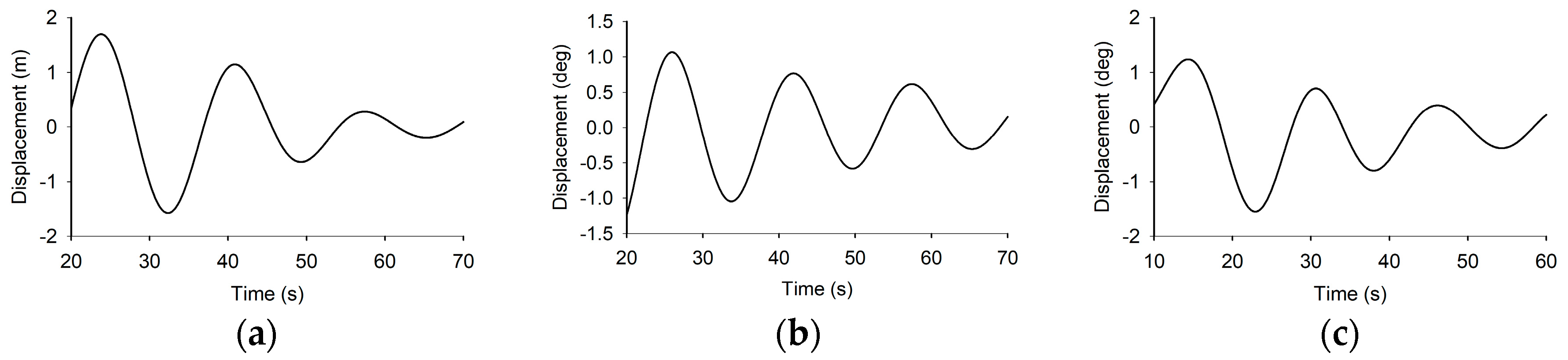
The free decay experiments of the platform with 24 WECs, which are rigidly fixed at the platform, were conducted by KRISO (Korea Research Institute of Ships and Ocean Engineering).
Figure 6 shows the free decay results of heave, roll, and pitch. To correctly estimate the non-dimensional damping coefficient, well-developed decay responses have been used, obtained by removing the first 20 s from the heave and roll time-histories and the initial 10 s from the pitch one. The natural frequencies of the platform and the WECs are tabulated in
Table 3.
The non-dimensional damping (
) is given by:
where
and
are two successive positive or negative maximum displacements. The damping coefficient can be obtained by:
in which
and
are the hydrostatic coefficient and the natural frequency, respectively. The damping coefficient from Equation (6) includes the radiation damping coefficient as well as the viscous damping coefficient. In order to obtain only the viscous damping coefficient, the radiation damping coefficient computed by WAMIT at the natural frequency should be subtracted. In the case of WEC, the heave free decay test was previously carried out by Kim et al. [
15]. Since the free decay test by KRISO has been carried out for the 24 WECs, which were fixed to the platform and not allowed to move in heave independently, the heave viscous damping of the platform without WECs can be simply estimated by subtracting the linearized viscous damping coefficient of the 24 WECs. The viscous damping coefficients of the platform and each WEC are presented in
Table 4.
The mooring lines play an important role in platform stiffness and the mooring lines increase the damping effect onto the floating platform because of the lines drag force. In this study, the effect of the mooring lines was simply considered as the linearized mooring line stiffness. To obtain the linearized mooring line stiffness, static offset simulation was carried out in time domain using the coupled hull-mooring dynamic analysis program HARP/CHARM3D with finite element mooring line models [
16,
17]. By pulling the floating platform, the simulation program estimates the restoring force from the mooring lines. The slopes from the force-displacement diagram at the platform origin indicate the linearized mooring line stiffness coefficients. The mooring line stiffness in the frequency domain analysis should be determined at the platform mean offset position with the wind-wave environment. However, the mooring stiffness in this study was calculated at the initial position of the platform for simplicity.
4. Dynamic Motion Analysis
The dynamic motion responses of the floating platform and the WECs can be obtained by solving the coupled equations of motion presented in Equations (1)–(4).
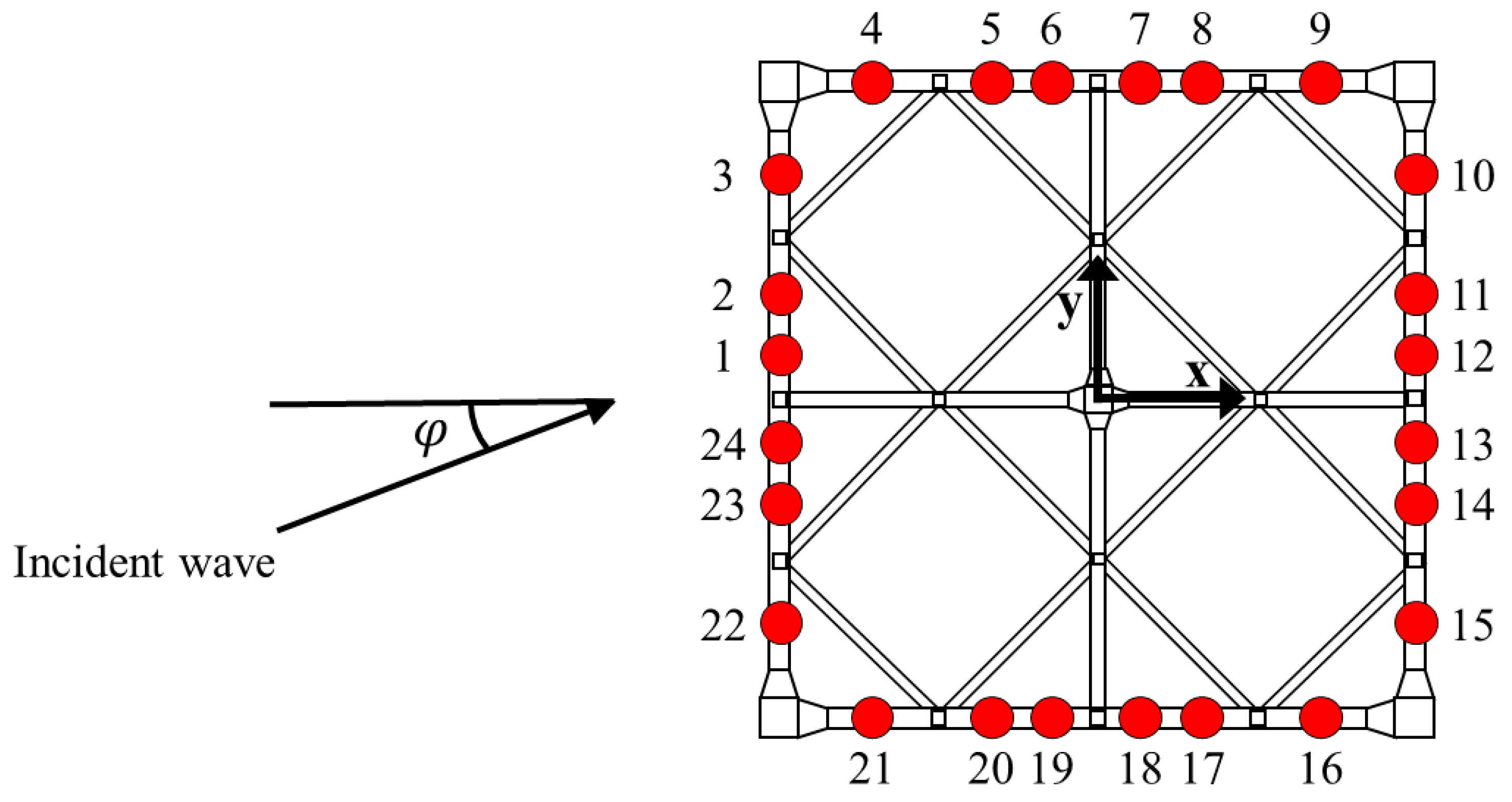
Figure 7 shows the platform and multiple WEC array configuration. For convenience, each WEC is numbered from 1 to 24 in a clockwise manner. Two different wave heading angles,
φ, were taken into account for the analysis: 0.0 deg and 22.5 deg. In particular, 22.5 deg is the dominant wave heading angle of the installation site. The incident regular wave frequency range for the simulation is from 0.02 to 1.6 rad/s and its amplitude is 1 m.
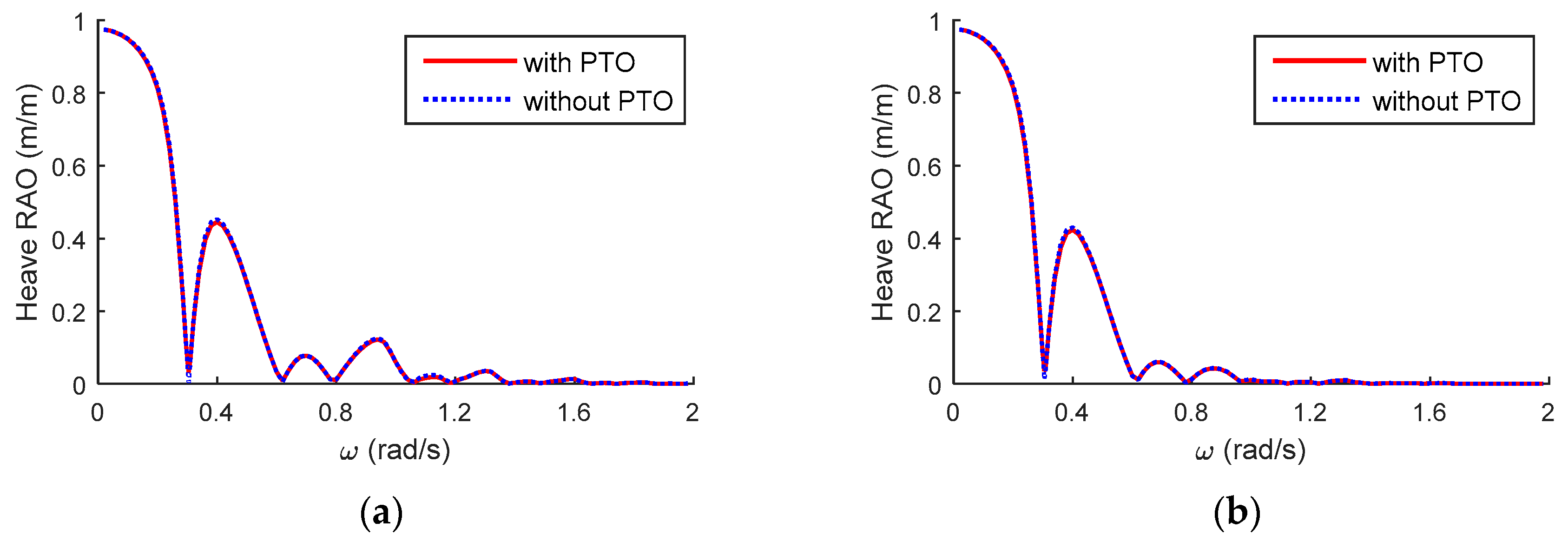
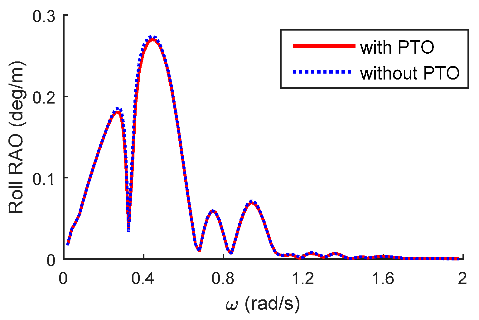
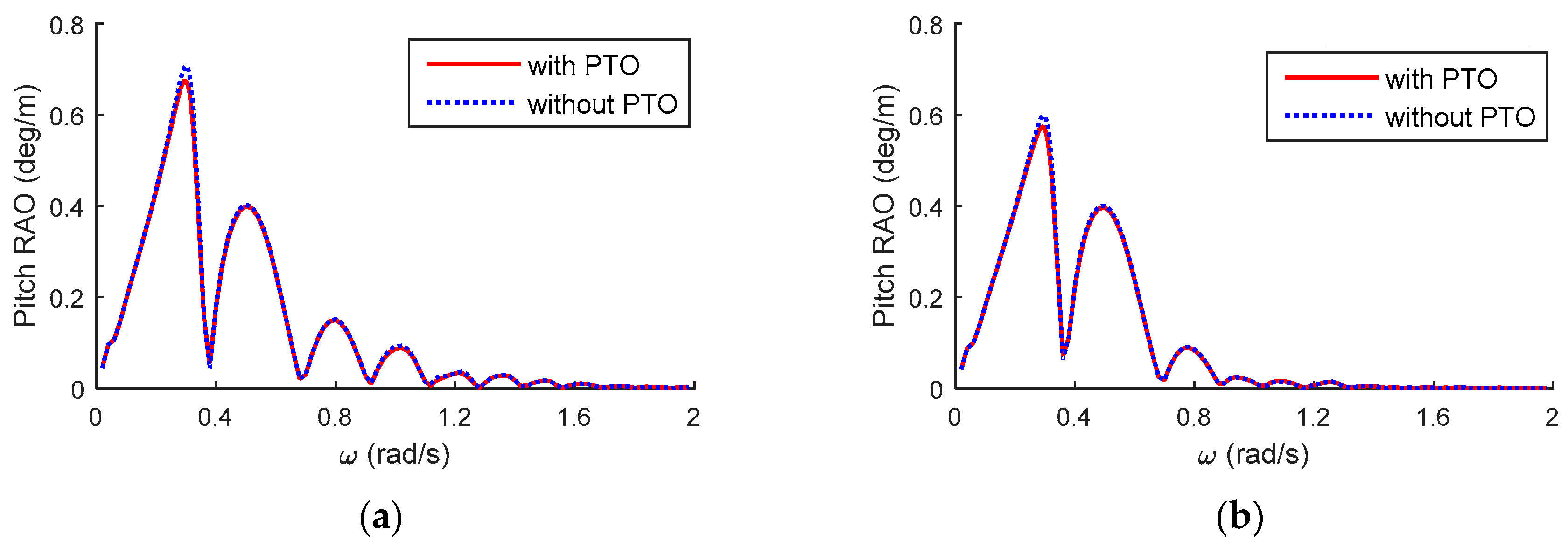
Figure 8,
Figure 9 and
Figure 10 show the platform response amplitude operator (RAO) for heave, roll, and pitch motion when linearized viscous damping is considered. As can be seen in the figures, PTO damping hardly influences the platform motion. This is because the PTO damping force is much smaller than the viscous damping force of the platform. The platform roll does not occur in the case of a 0.0 deg wave-heading angle because the platform is symmetric about that direction.
Figure 11,
Figure 12,
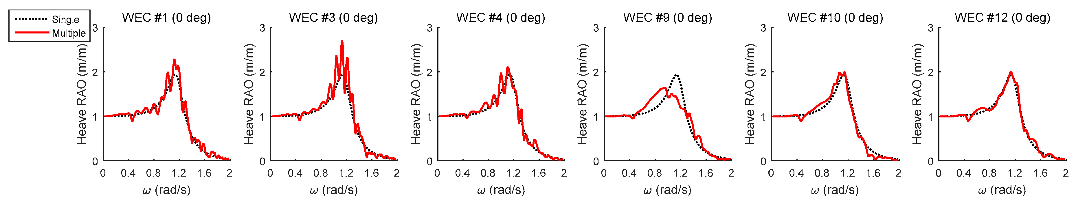
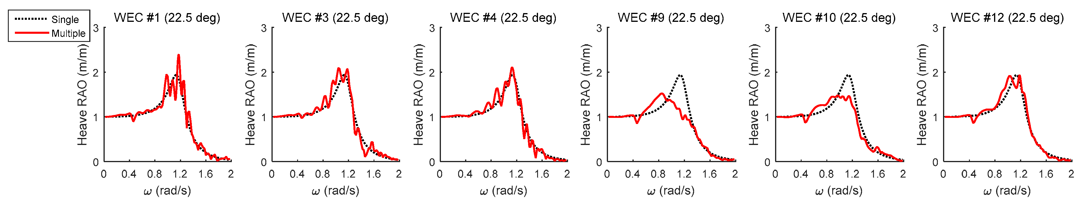
Figure 13 and
Figure 14 show the heave RAOs of each WEC when the wave-heading angle is 0.0 deg and 22.5 deg. In the case of a 0.0 deg wave heading angle, the multiple WECs are symmetrically located about the
x-axis. In particular, the WECs near the main columns (#3, #4, #9, #10) and the WECs in the middle of the array (#1, #12) are in these figures. In order to see the changes in the heave RAOs according to the wave-heading angle, the same WECs are chosen and shown when the wave-heading angle is 22.5 deg in
Figure 12 and
Figure 14, although the WEC array is asymmetrical. Depending on the location of the WECs, the heave responses show noticeably different trends. For example, the WECs located on the weather side (#1, #3, #4) have more fluctuations of RAO, while the WECs on the lee side (#9, #10, #12) have relatively mild heave RAOs as can be seen in
Figure 11 and
Figure 13. In the case of the oblique wave heading in
Figure 12 and
Figure 14, a similar trend remains valid.
Firstly, to see the coupled effect between the platform and the multiple WECs, the heave motions of the WECs in the array have been simulated and compared with that of a single WEC in
Figure 11 and
Figure 12. The result of the multiple WECs is denoted by the solid lines. The heave RAO of the single WEC was computed by placing one WEC at the origin without the platform and neighboring WECs and it is denoted by the dotted lines in these figures. The RAO of the single WEC also includes the damping from the PTO mechanism, radiation potential, and linearized viscous drag. The maximum heave RAO of the single WEC at its natural frequency (1.1750 rad/s) is nearly 2 and variations of RAO are very moderate compared to the cases with platform-WEC interactions. When platform-WEC interactions are considered, the heave responses of the WECs significantly differ from that of the single WEC.
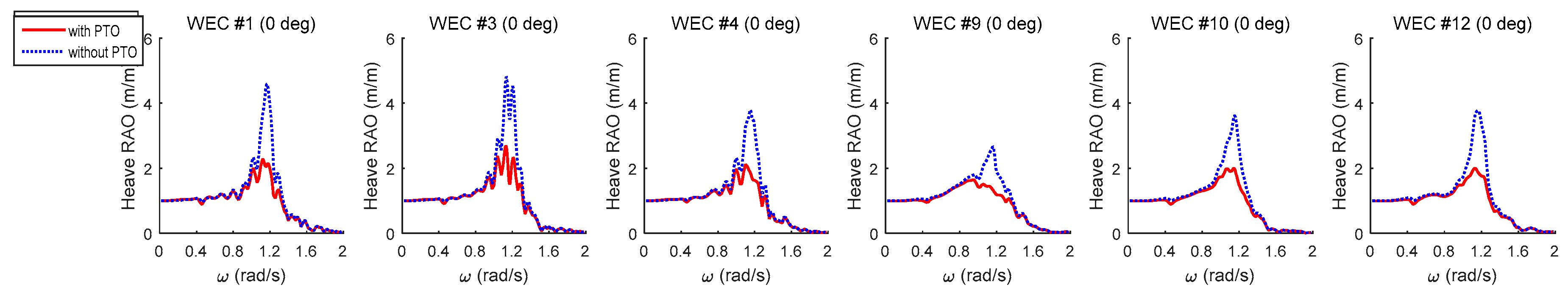
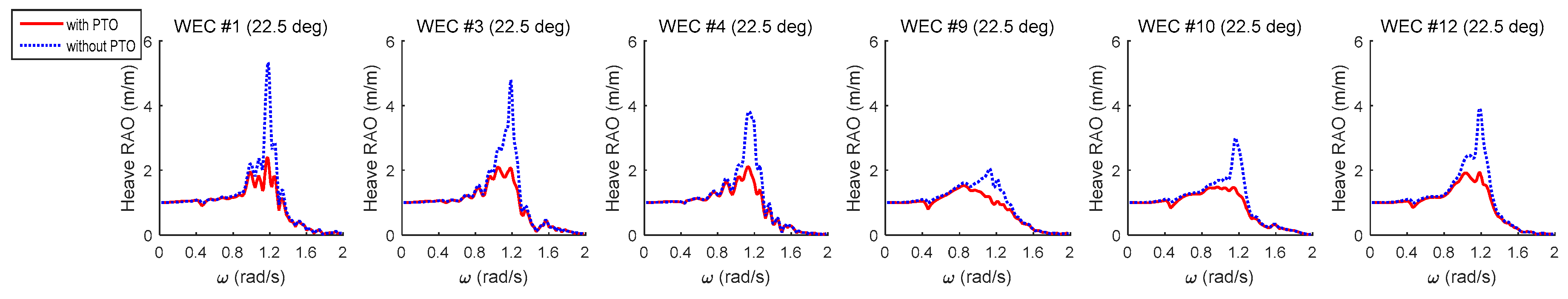
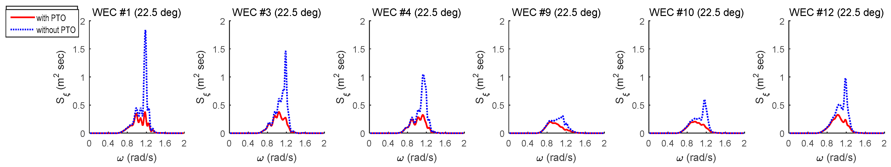
With regard to the PTO damping effect, the heave RAO of the WECs in array is shown
Figure 13 and
Figure 14. The dashed lines in these figures represent the heave RAOs without PTO damping effect. The solid lines represent the same responses with PTO damping effect. If PTO damping is not considered, the maximum heave RAOs of some of the WECs run to nearly 6. The resonance peak at the natural frequency is reduced once the PTO damping is included. Compared to the platform heave RAOs in
Figure 8, it is seen that the PTO mechanism can be an effective damper only for WECs.
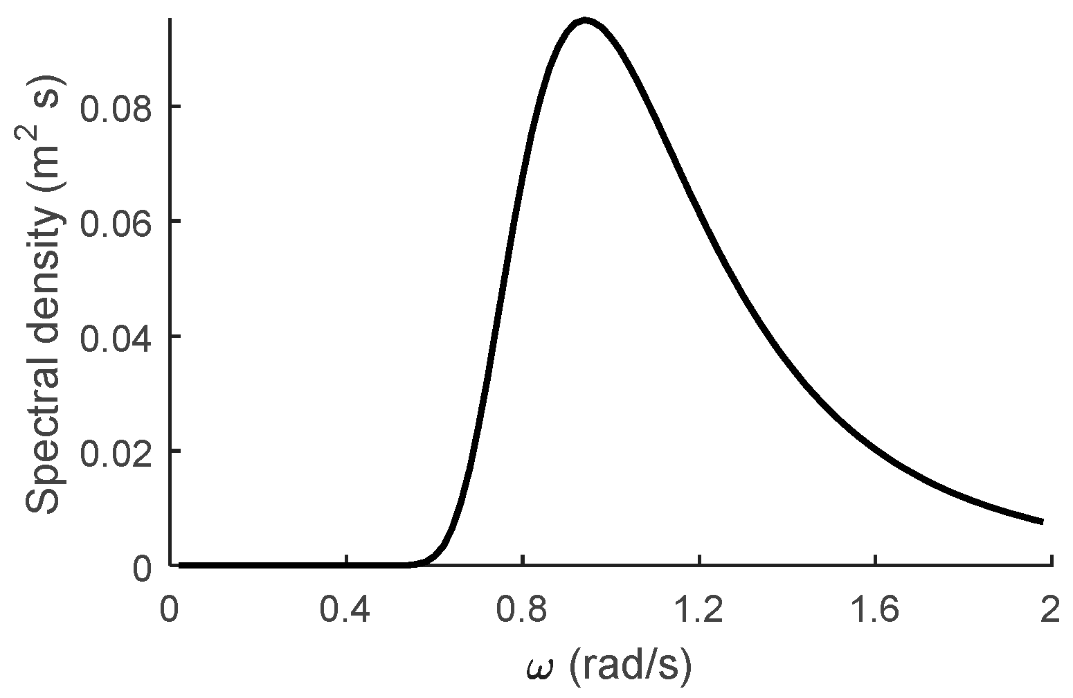
The heave motion responses in the real sea environment can be analytically obtained from the square of the RAO multiplied by the sea spectrum with a linear system assumption. The sea conditions at the installation site are represented by a Joint North Sea Wave Project (JONSWAP) spectrum (
Figure 15).
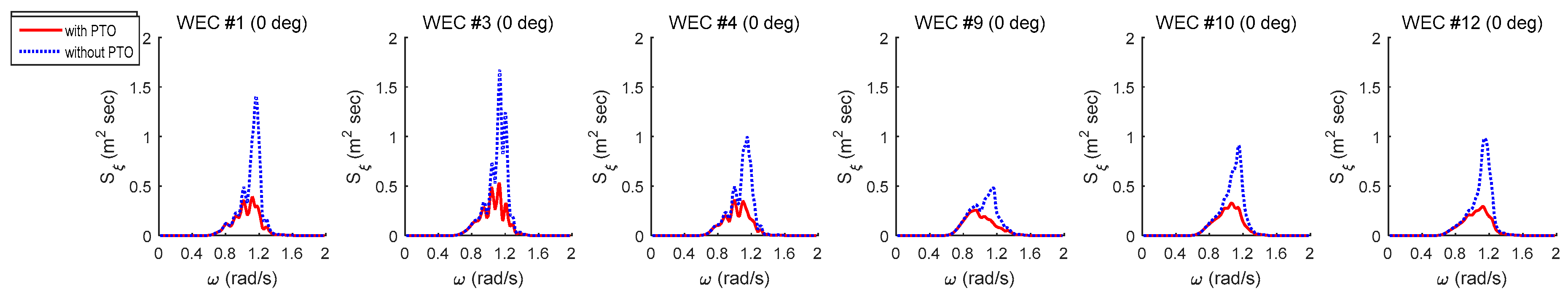
Figure 16 and
Figure 17 show the spectral response of the platform for heave motion related to the installation site. For both wave headings, the motion spectrum has a peak at the peak wave period near 0.942 rad/s and an additional peak near the natural frequency of WEC. The PTO damping only plays a role at the natural frequency of the WEC and significantly reduces the heave response.
5. Interaction Effect
In order to evaluate the interaction effect of the designed array configuration of multiple WECs on the extracted power, the interaction factor (
q-factor) is used [
18,
19]. The
q-factor represents the ratio of the total power extracted from the array configuration to that for the same number of isolated single WECs. If the
q-factor is greater than 1, the interaction effect is constructive with regard to energy yield. Otherwise, the interaction gives a destructive effect. The time-average power from the
-th WEC,
, is derived using the non-dimensionalized motion amplitude (RAO),
, as given by Equation (7). Equation (8) shows the
q-factor.
where
is the incident wave frequency,
is the incident wave amplitude,
, is the heave motion amplitude of the
-th WEC and
.
is the time-average power from the single WEC.
is the number of WECs.
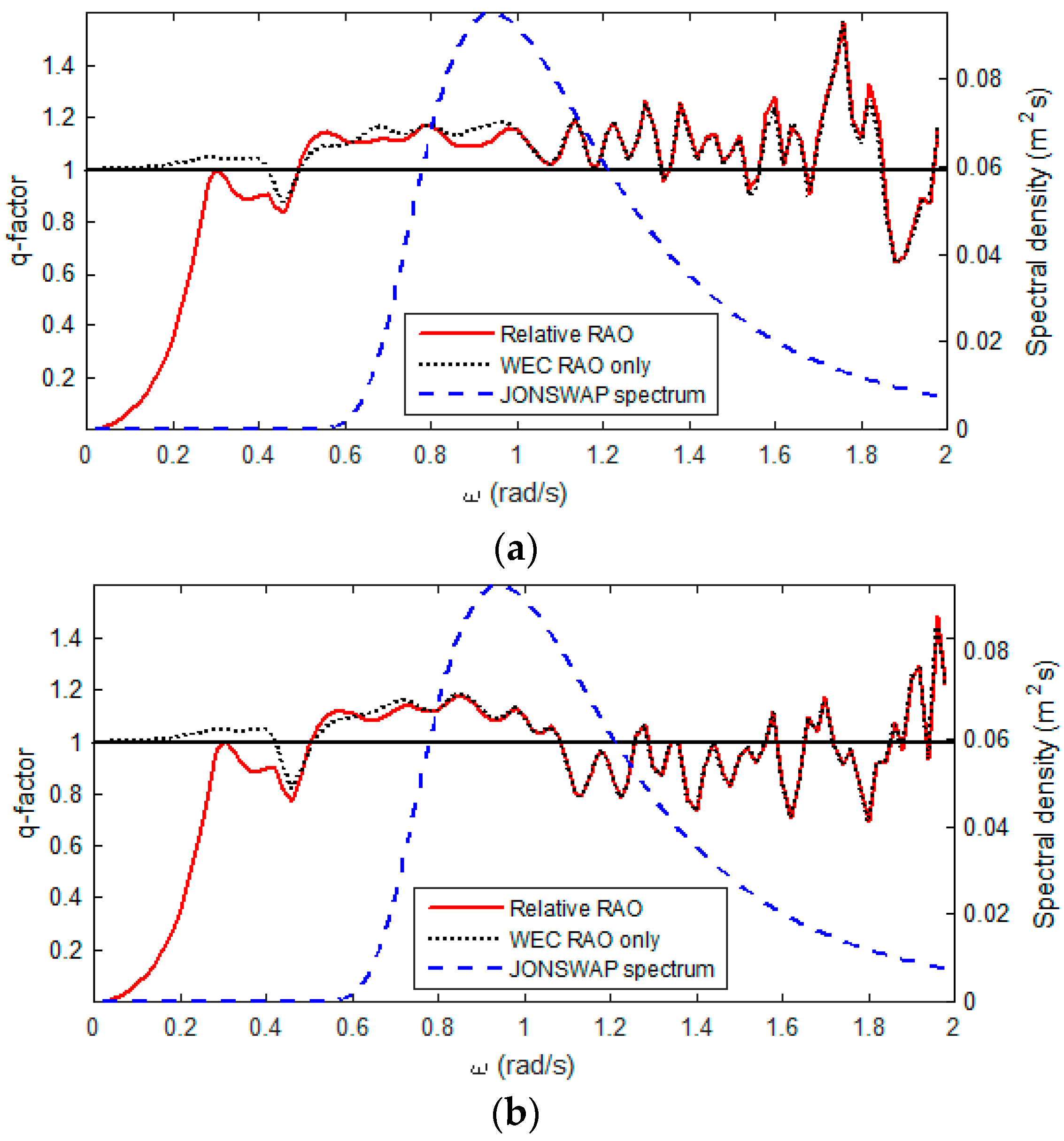
In order to check the interaction effect under the real sea environment, the designed wave spectrum of the installation site is shown as the dashed line in
Figure 18. In
Figure 18,
q-factors from the two wave-heading angles are illustrated. For the WECs placed on the floating platform, not on the earth-fixed structure, the power can be extracted from the relative heave motion between the platform and the WECs. For this reason, the effective
q-factor, which is obtained from the relative heave motion between the platform and each WEC, should be considered. For the calculation of relative heave motion, the complex form of RAOs is used in order to account for the phase differences. The solid lines in the figure represent the
q-factor considering relative heave motions. For comparison, the
q-factor from the WEC heave motion without platform heave is depicted with a dotted line.
As can be seen in this figure, within the frequency range where wave energy exists from 0.6 rad/s, the multiple WEC array arrangement with the platform is beneficial for both wave-heading angles; that is, the interaction between the platform and the WECs positively affects the overall energy yield. In the case of the 22.5 deg wave-heading angle, the q-factor tends to be less than 1 after about 1.1 rad/s where the wave energy still exists. The entire energy harvesting from the 0.0 deg wave-heading angle is better than that of the 22.5 deg heading because the q-factors within the wave frequency range are mostly greater than 1.
The gap between the dotted and solid lines represents the difference in q-factor incurred by a platform heave motion. In the low-frequency range below 0.4 rad/s, the gap is wide, which means that the relative heave motion is important for computing the q-factor. The q-factor considering relative heave motion (solid lines) below 0.3 rad/s converges to zero because the platform and the WECs move with a similar phase angle and magnitude, which results in nearly zero power production. In the high-frequency range over 1.0 rad/s, the difference can hardly be seen. This means that the platform heave motion does not affect the power production of WECs because of the small heave response of the platform in higher frequency range. The effect of relative motion near the peak wave frequency (0.9420 rad/s) makes a difference in power production for the 0.0 deg wave heading, while the effect is negligible for the 22.5 deg wave-heading angle. Regardless of the relative heave motion, the given multiple-WEC configuration has a positive effect on the overall energy harvest.
6. Conclusions
In this study, the coupled dynamic responses of a floating platform with wave energy converters were simulated and investigated by considering the hydrodynamic interactions between the platform and multiple WECs in the frequency domain. In addition, the PTO damping force induced by the relative heave motion between the platform and each WEC was taken into account. The linearized viscous damping force of the platform and each WEC was obtained from the free decay test and applied to the analysis as well.
Regarding the interaction effect, the heave motion of the WECs interacted with the platform and the adjacent WECs was investigated and compared with the motion of a single isolated WEC. The heave RAOs with interaction effect showed more fluctuations compared to that of the single WEC. It is hard to generalize the trend of the responses, but the WECs on the weather side showed bigger response compared to the WECs on the lee side. Also, PTO damping force significantly lowered the heave response of the multiple WECs whereas the platform heave response was only slightly influenced by it. The heave motion spectrum in the real sea environment was also estimated by a linear system assumption. The motion spectrum would be a good reference for estimating absorbed power from WECs in a given wave environment.
When it comes to the energy yield, the interaction of the array of multiple WECs was evaluated using the q-factor. In the case that wave heading angle is 0.0 deg, the q-factor was greater than 1 not only at the given peak wave frequency, but also within the overall frequency range. This means that the multiple array configuration adopted by this wind-wave hybrid platform is beneficial. When the wave heading is 22.5 deg, the q-factor was relatively smaller after 1.1 rad/s compared to the result of 0.0 deg wave heading. This could be because of the asymmetric WEC array to the wave heading. As the wave energy density still exists at the higher frequency region, the platform should be installed in alignment with the wave heading to extract more energy.
In this paper, it is assumed that a mathematical model of a floating platform and multiple WECs is a linear system that can quickly and simply estimate the system performance in the frequency domain. This method is typically used when designing floating offshore structures in the initial design phase. However, robust system designs require more accurate and sophisticated analysis, including nonlinear excitation or nonlinear coupling terms. For instance, the nonlinear effects of this hybrid platform include aerodynamic and elastic loading of four wind turbines, quadratic viscous damping of submerged structures, and second order wave loading. Time-domain analysis can accurately predict the performance of the multiple WECs and platforms, and this is left as a future research topic. Simplified analysis without any nonlinear effects might either overestimate or underestimate the overall system performance. The present methodology gives directions to carry out an extended study by considering the nonlinear analysis in the future.


