A Unified Control Strategy for Inductor-Based Active Battery Equalisation Schemes

1
Clean Energy Automotive Research Institute, Hefei University of Technology, Hefei 230009, China
2
School of Electrical and Data Engineering, University of Technology Sydney, Ultimo, NSW 2007, Australia
*
Author to whom correspondence should be addressed.
Energies 2018, 11(2), 405; https://doi.org/10.3390/en11020405
Submission received: 27 January 2018
/
Revised: 5 February 2018
/
Accepted: 6 February 2018
/
Published: 9 February 2018
Abstract
:Series battery equalisation can improve battery charge and discharge reliability and extend battery life. Inductor-based battery equalisation schemes have the advantages of simple topologies and control strategies. According to the energy transfer pathway, inductor-based battery equalisation schemes can be divided into cell-to-cell and cell-to-pack equalisation schemes. The control strategies of the cell-to-cell schemes are simple; the inductor can only transfer energy between the neighbouring cells, so the equalisation speed is low. The cell-to-pack schemes are able to accomplish energy transfer between the cells and pack by charging and discharging the inductors. The equalisation speed is high, but the control strategies may be complex. In this paper, different equalisation topologies are reviewed, then a unified control strategy which is applicable to all of the inductor-based equalisation topologies is proposed. The equalisation speeds and efficiencies of these different schemes, including the newly-proposed unified control strategy, are analysed and compared. Based on the theoretical analysis, simulations, and experimental verifications, it is concluded that this unified control strategy can perform the battery equalisation process quickly and efficiently.
1. Introduction
A lithium-ion battery has certain advantages, such as large capacity and small size. Lithium-ion batteries are widely applied in the fields of electric vehicles and energy storage systems [1,2,3,4,5]. The voltage and capacity of a single lithium cell is too low to satisfy the demands of many electrical applications [6]; as a result, the cells should be connected in series. The production process and the external environment of the battery are different, leading to minor inconsistencies of the cells in a battery pack. After many charging and discharging cycles, the differences of the cell capacities become obvious, thereby decreasing the capacity of the battery pack [7]. In addition, the life of the battery pack decreases if the cells always have inconsistent capacities. Therefore, equalisation of batteries in series is necessary to avoid the overcharge or overdischarge caused by the cell inconsistency. Application of such equalisation techniques ensures the reliability of the pack.
Generally equalisation schemes consist of passive and active equalisation schemes. The passive equalisation scheme uses external power resistors to consume excessive energy of the cell. This scheme has disadvantages, such as power loss and circuit heat [8,9,10]. The active equalisation scheme includes methods based on inductors, capacitors, multi-tap transformers, or complex bidirectional DC/DC converters [11,12,13,14,15,16,17]. Compared to the capacitor-based equalisation scheme, the inductor-based equalisation scheme has the advantages of simple switching logic and portability. Compared to schemes based on the multi-tap transformer and complex bidirectional DC/DC converter, the inductor-based equalisation scheme has the advantages of small size, low cost, and simple control strategy. Therefore, the inductor-based equalisation scheme has received considerable attention in recent years.
There are several inductor-based equalisation schemes. According to the energy transfer mode, these schemes can be divided into the cell-to-cell schemes and the cell-to-pack schemes. A typical cell-to-cell scheme is introduced in [18], where the bidirectional non-dissipative current diverter is applied. Each diverter contains an inductor and two bidirectional switches. The charge moves from the most charged cell to an adjacent cell by a buck–boost operation. It can also be treated as an integrated individual cell equaliser (ICE) based on the DC–DC converter [19,20]. Every two adjacent cells require one cell equaliser, and the equalisation speed is low. The cell-to-pack schemes can accelerate the speed of equalisation. An efficient battery equalisation scheme in an electric vehicle is proposed in [21]. The equalisation circuit is composed of two groups of switches and an inductor. This circuit is, indeed, a bridge-type equalisation circuit. The inductor can realise energy transfer between the whole battery pack and a single cell. There is only one inductor in the circuit, and the equalisation speed is high. However, there are several switching devices, and the control logic is complex. A novel equalisation topology with symmetrically-distributed inductors is described in [22]. Each cell has an equalisation module, which contains a diode, a switch, and an inductor. The scheme can realise high-speed equalisation, but additional switches are required. As a result, the reverse diode of the metallic oxide semiconductor field effect transistor (MOSFET) is not effectively utilised. In addition, the number of the cells should be even. Among these inductor-based equalisation schemes, the cell-to-cell scheme with bidirectional non-dissipative current diverters is the most common scheme in industrial applications [23,24]. To accelerate the equalisation speed of the scheme, a layer-based battery charge equalisation system is designed in [25]. However, its application is still limited to special scenarios. Most of the control strategies of the cell-to-pack schemes are complex, hindering their widespread application [26]. Although the series-based, layer-based, or multi-staggered battery equalization systems have existed for a long time, a comparison between these different systems is still lacking.
In this paper, a new, simplified, inductor-based topology which can realise cell-to-pack energy transfer is presented. Each cell corresponds to a bidirectional switch. After analysing properties of different existing battery equalisation systems, a unified control strategy is proposed so as to be applicable to all the inductor-based equalisation topologies. The equalisation speed and efficiency of the equalisation schemes are discussed. The advantages and disadvantages of different topologies are compared. The simulation and experimental results of the above-mentioned schemes are given to verify the theoretical analysis. The structure of the paper is as follows: Section 2 recalls different inductor-based active battery equalisation topologies. Their working principles are analysed. Section 3 analyses the working modes of the new simplified cell-to-pack equalisation topology. Section 4 discusses the unified control strategy and its application on different topologies. In Section 5, a comparison of different equalisation topologies under the proposed control strategy is given. The equalisation speed and efficiency are analysed in detail. Section 6 shows the simulation and experimental results of the equalisation schemes. Their applicable scenarios are also given.
2. Inductor-Based Equalisation Topologies
The inductor-based equalisation topologies are summed up here together with the comparison between them.
2.1. Cell-to-Cell Equalisation Topologies
The main topology of the ICE is shown in Figure 1, where D1 and D2 are the anti-parallel diodes of S1 and S2. The charge and discharge of L1 can realise energy exchange of Cell 1 and Cell 2. Their voltages are U1 and U2.
The residual capacity of the cell can be characterised by the state of charge (SOC). According to the Nernst model [27], the relationship between the cell voltage and SOC can be expressed as:
where U0 is the open circuit voltage, R is the internal resistance, K is a constant coefficient, and ic contains the external current generated by the charging/discharging process and the inner current generated by the equalisation circuit. The parameters in Equation (1) can be identified by experiment [28].
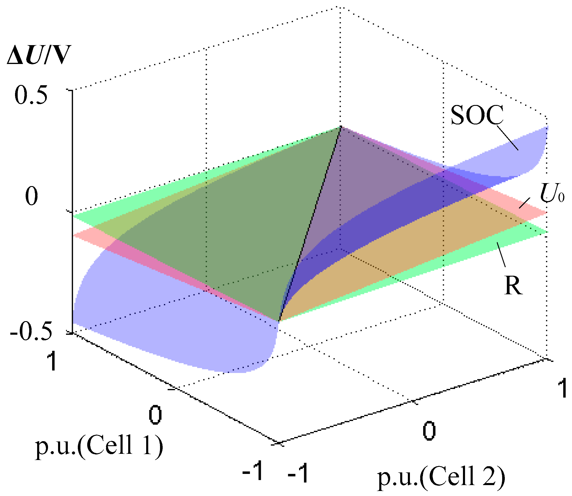
Different cells have different SOCs. The open circuit voltages and internal resistances may also be different if the cells are aged. In this paper, a Li-ion battery is applied and the capacity is 20 Ah. According to the parameter identification of a new cell, U0 is 3.44 V, R is 3 mΩ, and K is 0.1. Figure 2 shows the influence of the parameters U0, R, and SOC on U. The x-axis and y-axis are the standard unitary values of Cell 1 and Cell 2, respectively. The z-axis is the voltage difference ΔU. ic is 0.1 C (discharge-rate), which is 2A. The standard unitary values of the parameters are listed in Table 1.
When the cells are new, the differences of the open circuit voltages and internal resistances are slight. Therefore, in the ICE, the equalisation of SOC1 and SOC2 can be realised by the equalisation of U1 and U2. When the cells are old, the influence of SOC on U is much more significant than that of the other parameters, therefore, the equalisation of U1 and U2 is also effective to equalise the SOC.
Figure 3 shows the equalisation structure of the cell-to-cell scheme. Figure 3a is the series-based battery equalisation system, where the equalisation speed is low. Figure 3b is the layer-based battery equalisation system. The number of the ICEs is the same in the two systems. There are N cells connected in series. The number of the ICEs is N − 1. The ICEs include N − 1 inductors and 2N − 2 switches. The equalisation speed of the layer-based system is higher. However, the number of the ICEs should be a power of 2.
2.2. Cell-to-Pack Equalisation Topologies
Figure 4a shows the topology of the bridge type equalisation scheme. There are N cells connected in series. The inductor L is the only energy storage device. There are 2N + 2 switches. If cell Un needs to discharge, then the switches SPn and SNn+1 turn on and L is charged. After SPn and SN1 turn off, SP1 and SNN+1 turn on and L releases energy to the battery pack [29]. In addition, the topology can operate in the pack-to-cell mode. If the cell Un must be charged, then the inductor releases energy to Un. The disadvantage of this scheme is that there are too many switches, and the control system is complex.
Figure 4b shows the topology of the inductor symmetrically distributed equalisation scheme. There are N inductors and N switches, and N is an even number. For any n less than or equal to N/2, if the cell Un must discharge, then the switch Sn turns on, and the corresponding inductor Ln is charged. After Sn turns off, Ln releases energy to the downstream cells. When n is greater than N/2, Ln releases energy to the upper cells. The control strategy based on the SOC is applied. The duty cycle of the switches can be expressed as follows:
where Spn is the SOC of the cell Un, T is the switching cycle, and Ts is the sampling cycle. In the analysis of [19], the equalisation scheme operates in the stage that the voltages of the cells are close to the nominal voltage UB. As a result, the duty cycle does not apply to the whole charging/discharging process.
Figure 5 shows the simplified cell-to-pack topology, where U1–UN are the voltages of the cells, L1–LN−1 are the energy storage inductors, S1–SN are the power switches, and D1–DN are the anti-parallel diodes of S1–SN. These diodes can provide a continuous flow path of the inductor current. The principle of the topology is similar to that of the inductor symmetrically distributed equalisation topology. However, the number of inductors here is smaller and the freewheeling diodes can be replaced by the body diodes of the MOSFETs. Thus, external diodes will no longer be needed.
There are N − 1 ICEs in Figure 5, which is the same as the cell-to-cell topologies. In Figure 3, each ICE has only two switches and any of them cannot be used in two or more ICEs. In contrast, the switches in Figure 5 can be shared by different ICEs, which makes the number of switches in the simplified cell-to-pack topology smaller than that in the cell-to-cell topologies.
According to Figure 5, there are N cells, and the equalisation topology requires N − 1 inductors and N MOSFETs. The circuit is very simple. The shorting problem occurs only when S1–Sn or D1–Dn are all turned on, which does not occur in principle. The case that S1–Sn are turned on at the same time corresponds to the situation that all the cells are being discharged without an external discharger. Similarly, D1–Dn freewheeling at the same time corresponds to the cells being charged without an external charger. During the balancing process, some of the cells are discharged, and some others are charged. Thus, S1–Sn or D1–Dn all being turned on cannot occur. In the control system, the speed of the driving signals of the switches cannot be at a high level at the same time.
3. Control Strategy of the Equalisation Topologies
3.1. Unified Control Strategy
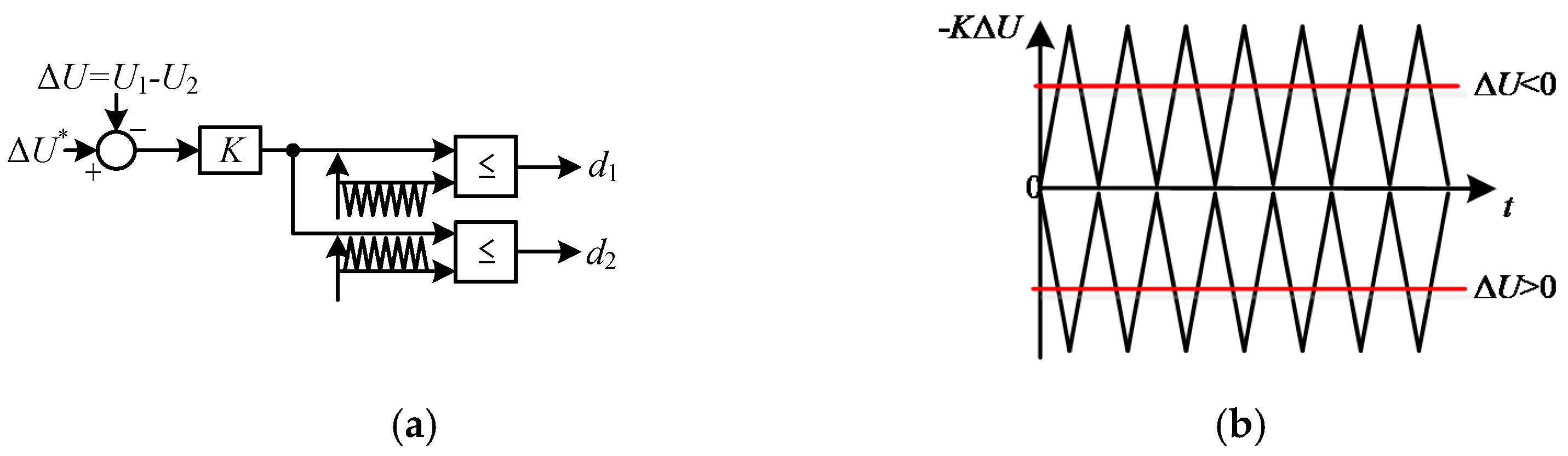
Figure 6 shows a unified control strategy of the inductor-based equalisation topologies. It is also the control strategy of the ICE. The closed-loop control strategy is shown in Figure 6a, where d1 and d2 are the driving signals of S1 and S2, ΔU is the voltage difference of U1 and U2, ΔU* is the reference of the voltage difference and should be 0 in the ideal condition. The positive constant K is the gain of the voltage error.
The output of the gain controller is −KΔU. Two different triangle carriers are compared in Figure 6b. The triangle carrier of S1 is the negative inverted triangle. The triangle carrier of S2 is the positive regular triangle. When the voltage U1 is higher than U2, −KΔU is less than zero. This triangle carrier does not intersect with the positive regular triangle, and S2 is off. S1 is controlled by Pulse Width Modulation (PWM). The more significant the difference of U1 and U2 is, the lower −KΔU is. In that case, the duty cycle of d1 increases, and U1 discharges quickly. Similarly, when U1 is lower than U2, the discharging process of U2 is managed by the closed-loop controller.
Figure 6c shows the control flowchart. If the voltage difference is higher than the upper limit εmax, then the corresponding switch works with the maximum duty cycle. If the voltage difference is higher than the lower limit εmin, then both of the two switches turn off.
Without the closed-loop control step in the dashed box of Figure 6c, the control strategy becomes the usual control strategy of the ICE, which is shown in Figure 6d. In that case, εmin can be treated as the charging threshold and εmax the discharging threshold. Note that εmin and εmax are very small values; thus, the equalisation speed can be improved. However, the cells may be overcharged or overdischarged. The equalisation result may not be good under the usual control strategy.
3.2. Application of the Unified Control Strategy
If the unified control strategy is applied in the cell-to-cell topologies, the difference between different ICEs in Figure 6 lies on the different values of ΔU. The application of the unified control strategy in the cell-to-cell topologies is shown in Figure 7a, where ΔU can be calculated as:
Figure 7b shows the application in the cell-to-pack topologies. If the voltage of the cell Un is higher than the average value, then the corresponding Sn switches, and ΔU can be rewritten as:
4. Comparison of the Equalisation Schemes
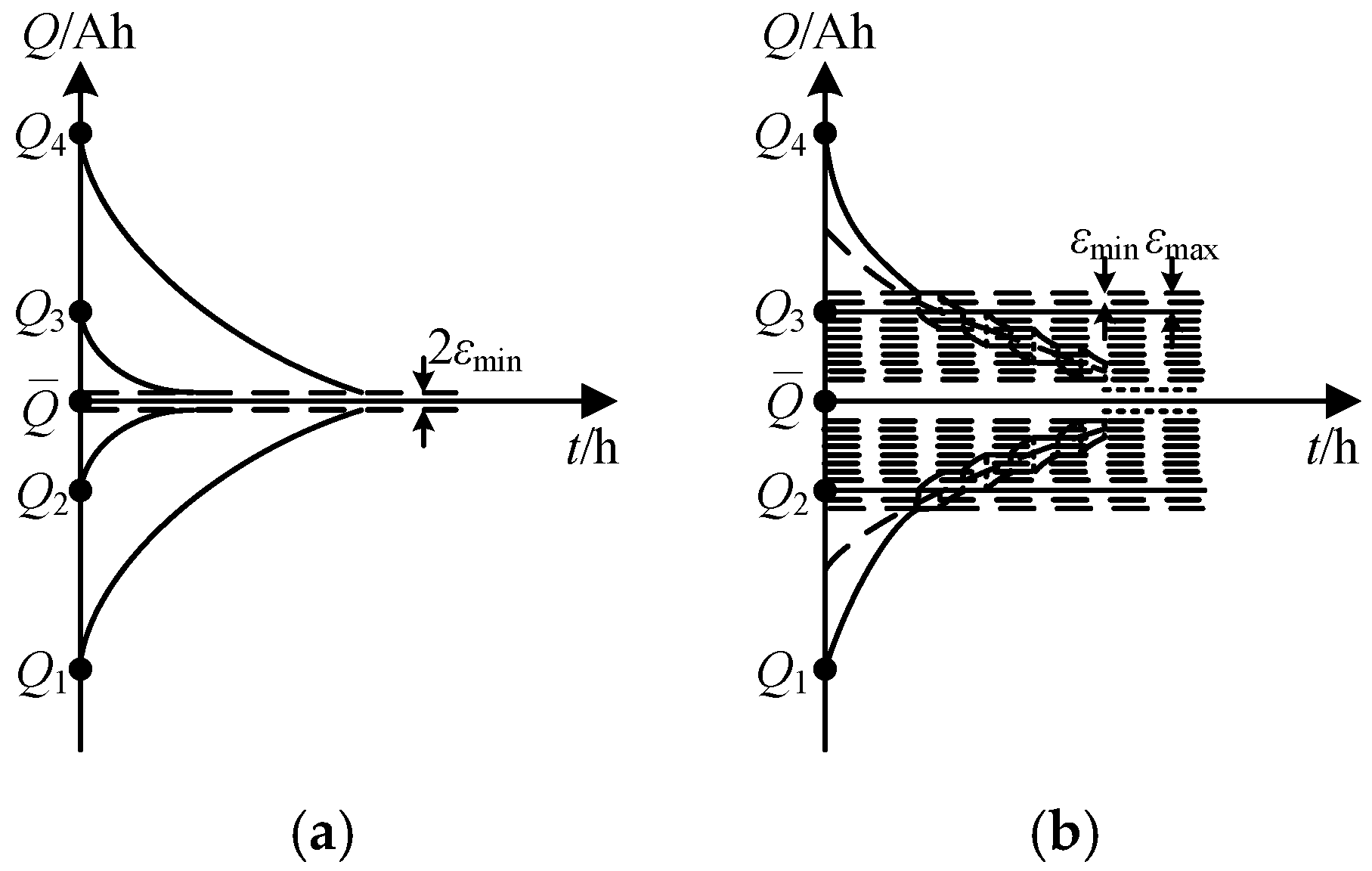
In the equalisation process, the capacity of Cell n can be expressed as:
where is the initial capacity of cell n. The maximum equalisation current of each cell has an upper limit to protect the cells. In order to simplify the analysis, the equalisation current of each cell is assumed to be the constant I. The charging threshold is set as εmin and the discharging threshold is εmax. Figure 8 shows the equalisation processes of the inductor-based equalisation schemes. The bridge-type equalisation scheme in Figure 4a is not the main focuses so it is not analysed in this paper.
In Figure 8a, the equalisation time is determined by the maximum difference of the cell capacity and the average value, which is expressed as:
The equalisation process is similar to that of the inductor symmetrically distributed equalisation scheme shown in Figure 4b, but its topology is simplified. If the pack is charged or discharged by an external charger, the equalisation time will not be affected and, thus, the speed of equalisation is high. However, the switches are shared in multiple ICEs, and they also work in series. Compared to the scheme shown in Figure 4b, the simplified scheme in Figure 4a has higher loss.
In the series-based equalisation scheme, energy can only be transferred cell by cell. If a cell is charged by one ICE and discharged by an adjacent ICE, the capacity will not change; however, the loss of the two ICEs cannot be avoided. Thus, the efficiency of the series-based equalisation scheme is low. Additionally, the equalisation time would be extended by the charging threshold εmin and the discharging threshold εmax. In Figure 8b, Cell 4 releases energy to Cell 3 and Cell 3 releases energy to Cell 2 in the beginning. Then Q3 does not change. If the difference between Q4 and (Q4 + Q3)/2 reduces to εmin, the ICE of Cell 4 and Cell 3 will stop working. The ICE of Cell 3 and Cell 2 continues working and Q3 reduces. If the difference between Q4 and (Q4 + Q3)/2 increases to εmax, the ICE of Cell 4 and Cell 3 starts to work again. This process would repeat multiple times, which results in a low equalisation speed. The additional time can be expressed as:
In the layer-based equalisation scheme, the equalisation time depends on the top ICE and can be calculated as:
This equalisation speed is high. Furthermore, the cell charged by one ICE and discharged by the adjacent ICE can be avoided and the equalisation efficiency can be improved.
Table 3 shows the characteristics of the equalisation schemes. Different equalisation schemes have different advantages and disadvantages, which further determine their applications.
In Table 3, the first column refers to the following five schemes:
- 1:
- The simplified equalisation scheme
- 2:
- The series-based equalisation scheme
- 3:
- The layer-based equalisation scheme
- 4:
- The inductor symmetrically distributed equalisation scheme
- 5:
- The bridge-type equalisation scheme
With the unified control strategy, the limit of the inductor symmetrically-distributed equalisation scheme described in [14] can be avoided. Indeed, if the method in [17] is adopted, external diodes will be needed, and the circuit will be slightly complicated. The number of cells in the layer-based equalisation scheme is required to be a power of 2. We can find that although the structure of the series-based equalisation scheme is not complex and it does not have any particular requirement on the number of cells, it still suffers from low speed and low efficiency. The simplified equalization scheme has a relatively simple structure, it can also work in a high speed efficiently, and does not have a specific requirement on the number of cells. The bridge-type equalisation scheme also does not require cell numbers to be a power of 2. Although its equalisation speed is high, it performs inefficiently, and its structure is very complex.
5. Simulation and Experimental Results
The simulation model of the equalisation scheme is established based on MATLAB/Simulink (R2012a, MathWorks, Natick, MA, USA). 16 cells are connected in series to form a battery pack. The initial SOC of these respective cells are 0.95, 0.94, 0.93, 0.92, 0.91, 0.9, 0.89, 0.88, 0.87, 0.86, 0.85, 0.84, 0.83, 0.82, 0.81 and 0.8. All the inductors are set to have the same inductance 20 μH.
Figure 9 shows the SOC of the cells with different equalisation schemes. The initial SOCs of these cells are different to each other. After the implementation of an equalisation scheme, the SOCs of these cells tend to be the same. The equalisation speeds of the simplified equalisation scheme and the layer-based equalisation scheme are high. The final SOCs of the three schemes are 0.868, 0.860, and 0.872, respectively. The equalisation efficiency of the layer-based equalisation scheme is the highest.
Figure 10 and Figure 11 show the key waveforms of the layer-based equalisation scheme and the simplified equalisation scheme. The switching frequency is 10 kHz. Figure 10a and Figure 11a show the current of the inductors decreases with time. It can be seen that the greater the distribution between initial SOC and the final equilibrium SOC is, the larger the corresponding balanced inductor current is. In Figure 11a, the inductor current in the simplified equalisation scheme drops to zero for a short period of time, indicating that it can achieve fast equalization. Figure 10b and Figure 11b show the current of the switches. The changes of the current are similar to that of the SOCs. Figure 10c and Figure 11c show the voltage of the switches. In Figure 11c, the maximum voltage of the cells is the sum of the cell voltages, and it is higher than the switch voltage of the layer-based equalisation scheme. In the layer-based equalisation scheme, the average of the voltage stress of the switch is lower than that of the simplified equalisation scheme.
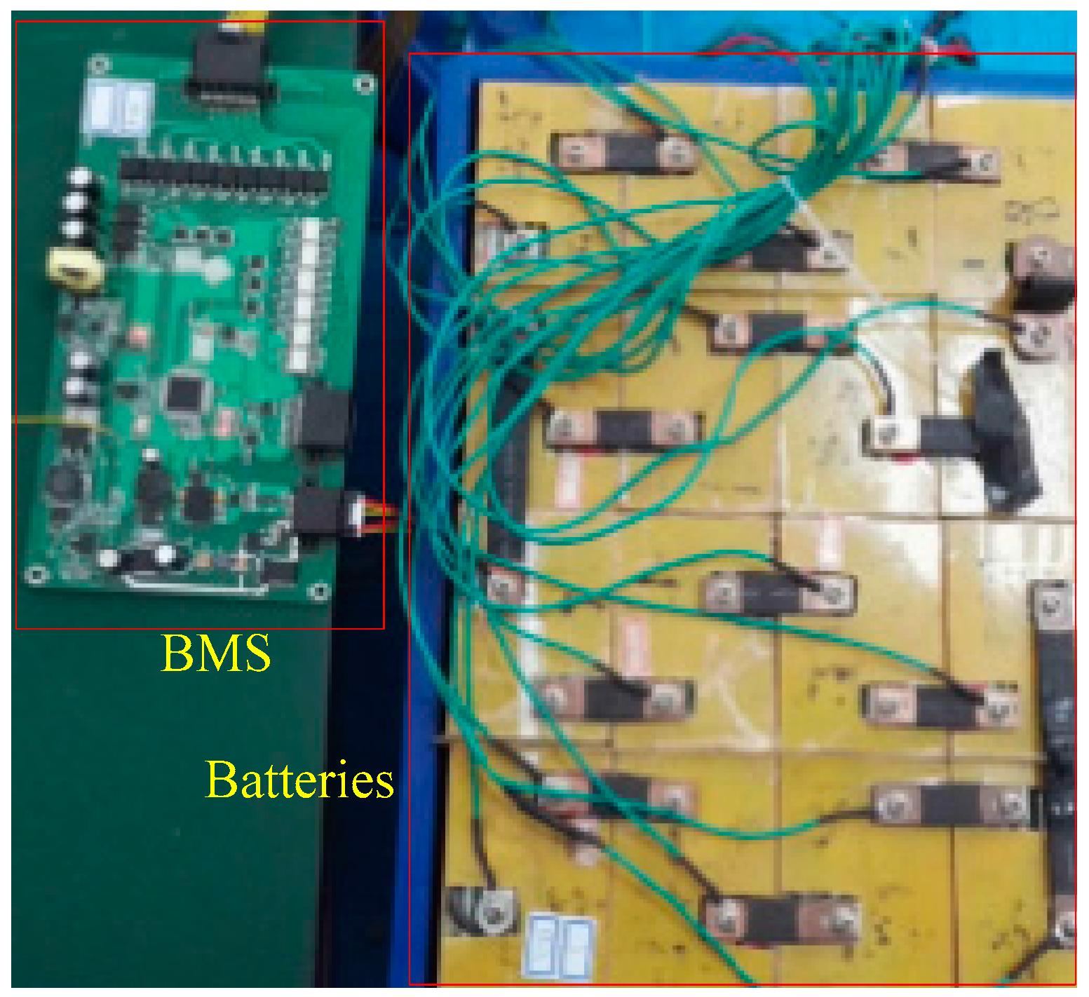
From the above comparison of the different equalisation schemes, the simplified equalisation scheme has simpler structure and higher equalisation speed. Thus, an experiment has been designed to implement the simplified equalisation scheme. An equalisation principle prototype was established. The parameters are the same as that of the simulation. Figure 12 shows the experimental device. The equalisation circuit is integrated with the battery management system (BMS). The control strategy is also implemented by the BMS.
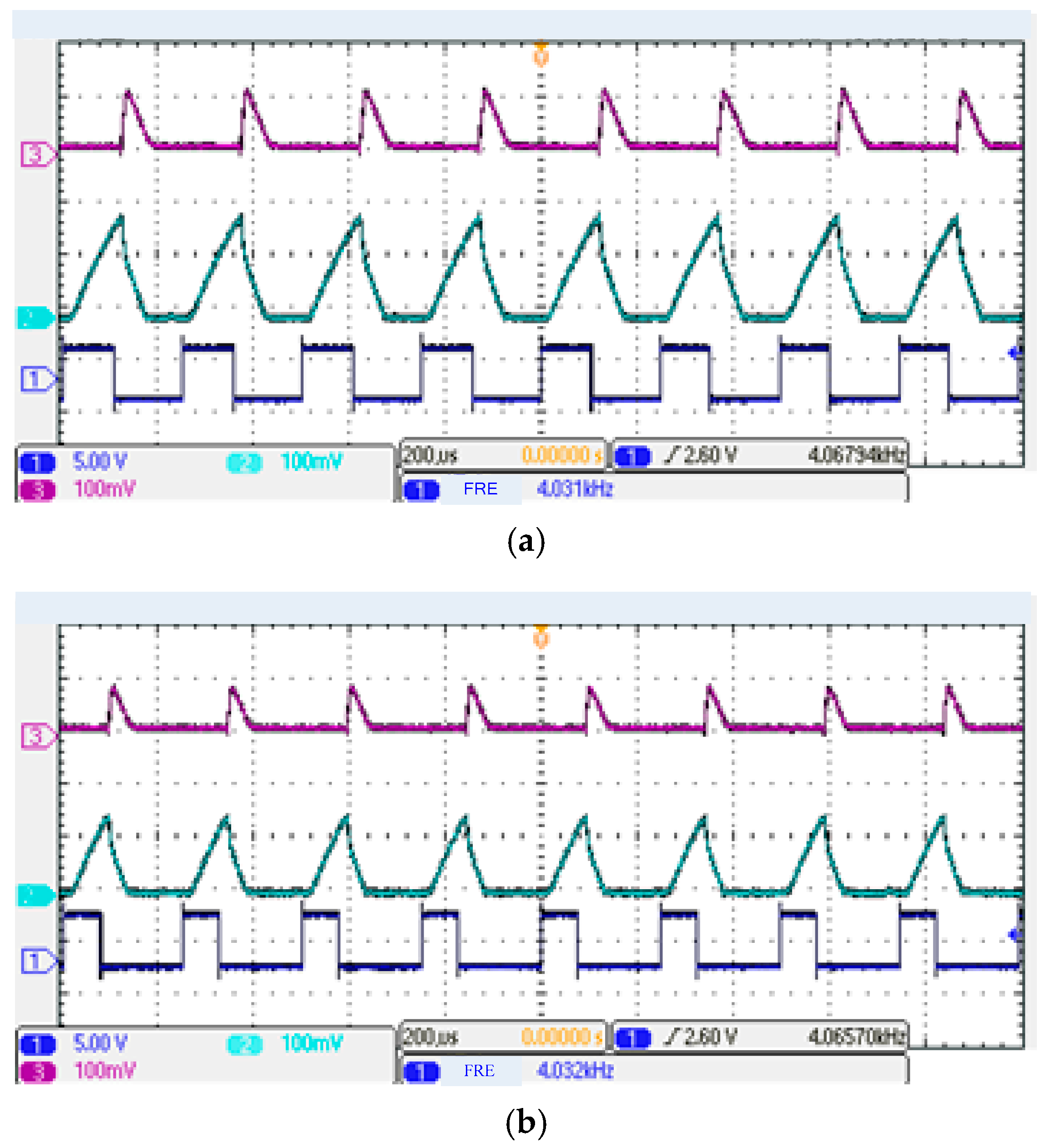
Figure 13 shows the key waveforms with different duty ratios. These waveforms in Figure 13 include the inductor current iL_1, the charging current of the bottom cell iU_N, and the driving signal of S1. The waveforms are consistent with the theoretical analysis in Section 3.
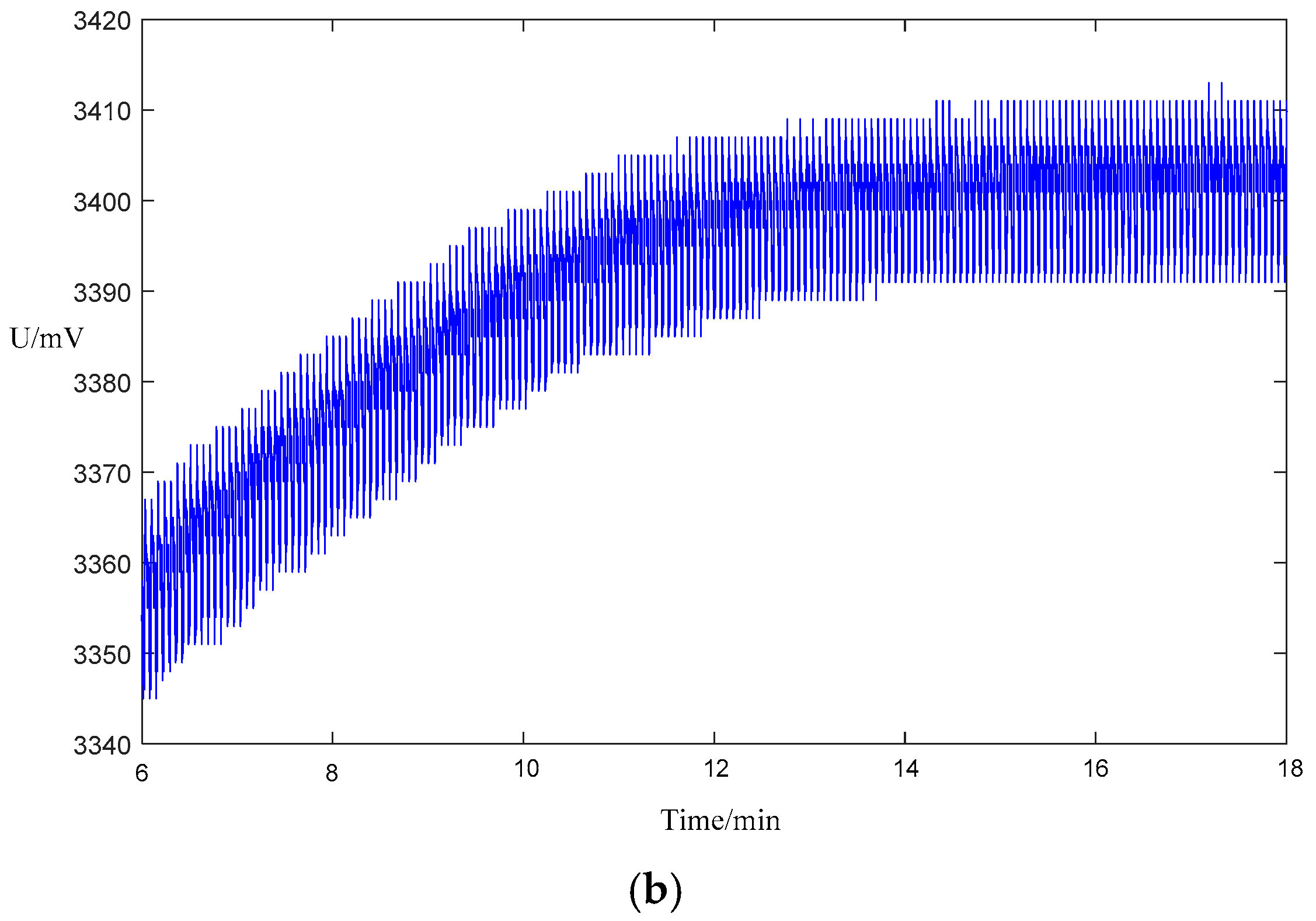
Figure 13 shows the distribution of the cell voltage. In Figure 14a, the difference of the relevant voltage is obvious. In Figure 14b, the equalisation scheme is applied; as a result, the distribution of the cell voltage is narrower. We can learn from Figure 14 that the distribution of the cell voltage becomes much smaller, which verifies that the equalization scheme works perfectly. The experimental results with and without equalisation demonstrate that the equalisation scheme can equalise the battery pack.
6. Conclusions
After reviewing different existing studies on inductor-based active battery equalisation schemes, a unified control strategy is proposed in this paper. These different equalisation schemes are then analysed and compared. A common layer-based equalisation scheme has obvious advantages, but the number of the cells must be a power of 2, which increases exponentially when the system is large. Thus, the application of this scheme is limited. In the simplified equalisation scheme, rated voltage needs to be higher than the voltage of the battery pack, which is sometimes a disadvantage of this scheme. Note that the number of the cells in a BMS is less than 16 due to the limitations of the ports on the control chip are limited. Therefore, MOSFETs, which can only withstand the low-voltage, can still meet this requirement. The newly-proposed unified control strategy is applicable to all of the schemes and can realise real-time equalisation which meets the requirement of actual use. Through the quantitative analysis of the existing typical schemes, the advantages and disadvantages of different schemes are compared, which provides a basis for balanced designs. As a future work, a new topology of equalization will be studied to apply to a chain-stored, cascaded, multilevel converter.
Acknowledgments
The authors would like to thank National Natural Science Foundation of China (51607052) and the National Natural Science Foundation of China (61603120), as well as the reviewers for reviewing the manuscript.
Author Contributions
Yao He helped to guide many professional problems of English paper writing. Zhihao Wan performed the data analysis and wrote the manuscript. Xintian Liu contributed to analysis and manuscript preparation. Xinxin Zheng is the corresponding author of the manuscript. Guojian Zeng, Jiangfeng Zhang revised the manuscript.
Conflicts of Interest
The authors declare no conflict of interest. The founding sponsors had no role in the design of the study; in the collection, analyses or interpretation of data; in the writing of the manuscript; nor in the decision to publish the results.
References
- Yeo, J.S.; Yoo, E.J.; Ha, S.H.; Cheong, D.I.; Cho, S.B. Electrochemical properties of large-sized pouch-type lithium ion batteries with bio-inspired organic cathode materials. J. Power Sources 2016, 313, 91–95. [Google Scholar] [CrossRef]
- Sbarufatti, C.; Corbetta, M.; Giglio, M.; Cadini, F. Adaptive prognosis of lithium-ion batteries based on the combination of particle filters and radial basis function neural networks. J. Power Sources 2017, 344, 128–140. [Google Scholar] [CrossRef]
- Rahe, C.; Figgemeier, E.; Sauer, D.U. Investigation of an Automotive Battery Pack Cell. In Meeting Abstracts; The Electrochemical Society: Pennington, NJ, USA, 2017; Volume 4, p. 401. [Google Scholar]
- Hannan, M.A.; Hoque, M.M.; Ker, P.J.; Begum, R.A.; Mohamed, A. Charge equalization controller algorithm for series-connected lithium-ion battery storage systems: Modeling and applications. Energies 2017, 10, 1390. [Google Scholar] [CrossRef]
- Gao, Z.; Chin, C.S.; Chiew, J.H.K.; Jia, J.; Zhang, C. Design and Implementation of Smart Lithium-Ion Battery System with Real-Time Fault Diagnosis Capability for Electric Vehicles. Energies 2017, 10, 1503. [Google Scholar] [CrossRef]
- Saw, L.H.; Ye, Y.; Tay, A.A. Integration issues of lithium-ion battery into electric vehicles battery pack. J. Clean. Prod. 2016, 113, 1032–1045. [Google Scholar] [CrossRef]
- Castano-Solis, S.; Serrano-Jimenez, D.; Gauchia, L.; Sanz, J. The Influence of BMSs on the Characterization and Modeling of Series and Parallel Li-Ion Packs. Energies 2017, 10, 273. [Google Scholar] [CrossRef]
- Fathabadi, H. High thermal performance lithium-ion battery pack including hybrid active–passive thermal management system for using in hybrid/electric vehicles. Energy 2014, 70, 529–538. [Google Scholar] [CrossRef]
- Gao, Z.; Chin, C.S.; Woo, W.L.; Jia, J. Integrated equivalent circuit and thermal model for simulation of temperature-dependent LiFePO4 battery in actual embedded application. Energies 2017, 10, 85. [Google Scholar] [CrossRef]
- Chiew, J.; Chin, C.; Jia, J.; Toh, W. Thermal analysis of a latent heat storage based battery thermal cooling wrap. In Proceedings of the 2017 COMSOL Conference—Call for Papers and Posters, Singapore, 4–6 October 2017. [Google Scholar]
- Bae, S.; Park, J.W.; Lee, S.H. Optimal SOC Reference Based Active Cell Balancing on a Common Energy Bus of Battery. J. Electr. Eng. Technol. 2017, 12, 29–38. [Google Scholar] [CrossRef]
- Choi, S.C.; Jeon, J.Y.; Yeo, T.J.; Kim, Y.J.; Kim, D.Y.; Won, C.Y. State-of-Charge Balancing Control of a Battery Power Module for a Modularized Battery for Electric Vehicle. J. Electr. Eng. Technol. 2016, 11, 629–638. [Google Scholar] [CrossRef]
- Kim, J.W.; Ha, J.I. Cell balancing method in flyback converter without cell selection switch of multi-winding transformer. J. Electr. Eng. Technol. 2016, 11, 367–376. [Google Scholar] [CrossRef]
- Chen, J.; Hou, S.; Deng, F.; Chen, Z. A bidirectional multi-port DC-DC converter integrating voltage equalizer. In Proceedings of the 2015 IEEE 6th International Symposium on Power Electronics for Distributed Generation Systems (PEDG), Aachen, Germany, 22–25 June 2015; pp. 1–6. [Google Scholar]
- Shang, Y.; Zhang, Q.; Cui, N.; Zhang, C. A cell-to-cell equalizer based on three-resonant-state switched-capacitor converters for series-connected battery strings. Energies 2017, 10, 206. [Google Scholar] [CrossRef]
- Chen, Y.; Liu, X.; Cui, Y.; Zou, J.; Yang, S. A multiwinding transformer cell-to-cell active equalization method for lithium-ion batteries with reduced number of driving circuits. IEEE Trans. Power Electron. 2016, 31, 4916–4929. [Google Scholar]
- Li, L.; Huang, Z.; Li, H.; Peng, J. A rapid cell voltage balancing scheme for supercapacitor based energy storage systems for urban rail vehicles. Electr. Power Syst. Res. 2017, 142, 329–340. [Google Scholar] [CrossRef]
- Kutkut, N.H. A modular non-dissipative current diverter for EV battery charge equalization. In Proceedings of the 13th Annual Applied Power Electronics Conference and Exposition, Anaheim, CA, USA, 15–19 February 1998; Volume 2, pp. 686–690. [Google Scholar]
- Nguyen, N.; Oruganti, S.K.; Na, K.; Bien, F. An adaptive backward control battery equalization system for serially connected lithium-ion battery packs. IEEE Trans. Veh. Technol. 2014, 63, 3651–3660. [Google Scholar] [CrossRef]
- Hoque, M.M.; Hannan, M.A.; Mohamed, A.; Ayob, A. Battery charge equalization controller in electric vehicle applications: A review. Renew. Sustain. Energy Rev. 2017, 75, 1363–1385. [Google Scholar] [CrossRef]
- Liu, H.; Xia, C. An efficient battery balancing scheme in electric vehicle. In Proceedings of the 2013 International Conference on Materials for Renewable Energy and Environment, Chengdu, China, 19–21 August 2014; Volume 2, pp. 541–544. [Google Scholar]
- Zhang, Y.; Lin, J.; Li, J. Dynamic charge equalization with inductor symmetrically distributed. Trans. China Electrotech. Soc. 2010, 25, 136–141. [Google Scholar]
- Arnaud, D.; Dubarry, M. Durability and Reliability of Electric Vehicle Batteries under Electric Utility Grid Operations. Part 1: Cell-to-Cell Variations and Preliminary Testing. Batteries 2016, 2, 28. [Google Scholar] [CrossRef]
- Goodarzi, S.; Beiranvand, R.; Mohamadian, M. Analyzing a resonant switched-capacitor converter for improving lithium-ion battery cells balancing speed. Modares Electr. Eng. 2016, 14, 48–57. [Google Scholar]
- Chen, H.; Zhang, L.; Han, Y. System-theoretic analysis of a class of battery equalization systems: mathematical modeling and performance evaluation. IEEE Trans. Veh. Technol. 2014, 64, 1445–1457. [Google Scholar] [CrossRef]
- Gallardo-Lozano, J.; Romero-Cadaval, E.; Milanes-Montero, M.I.; Guerrero-Martinez, M.A. Battery equalization active methods. J. Power Sources 2014, 246, 934–949. [Google Scholar] [CrossRef]
- Liu, X.T.; Qin, S.X.; He, Y.; Zheng, X.X.; Cao, C.R. SOC estimation of the lithium-ion battery with the temperature-based Nernst model. In Proceedings of the 2016 IEEE 8th International Power Electronics and Motion Control Conference (IPEMC-ECCE Asia), Hefei, China, 22–26 May 2016. [Google Scholar]
- Yang, F.; Xing, Y.; Wang, D.; Tsui, K.L. A comparative study of three model-based algorithms for estimating state-of-charge of lithium-ion batteries under a new combined dynamic loading profile. Appl. Energy 2016, 164, 387–399. [Google Scholar] [CrossRef]
- Liu, H.R.; Xia, C.Y. An active equalizer for serially connected lithium-ion battery cells. Adv. Mater. Res. 2013, 732, 809–812. [Google Scholar] [CrossRef]
Figure 1.
Integrated individual cell equaliser.
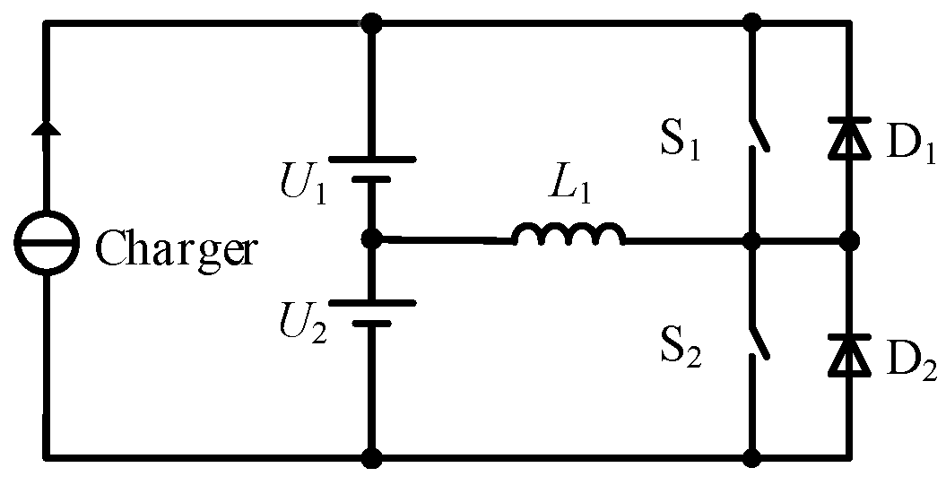
Figure 2.
The influence of parameters.

Figure 3.
Equalisation system control structure of the cell-to-cell scheme. (a) The series-based battery equalisation system; (b) the series-based battery equalisation topology; (c) the layer-based battery equalisation system; (d) the layer-based battery equalisation topology; and (e) the multi-staggered battery equalization topology.

Figure 4.
Topologies of the cell-to-cell equalisation scheme. (a) The bridge-type equalisation topology. (b) The inductor symmetrically-distributed equalisation topology.
Figure 4.
Topologies of the cell-to-cell equalisation scheme. (a) The bridge-type equalisation topology. (b) The inductor symmetrically-distributed equalisation topology.

Figure 5.
Simplified cell-to-pack topology.

Figure 6.
A unified control strategy for inductor-based equalisation topologies. (a) Closed-loop control strategy; (b) triangle carrier of the switches; (c) control flow chart; and (d) common control strategy.
Figure 6.
A unified control strategy for inductor-based equalisation topologies. (a) Closed-loop control strategy; (b) triangle carrier of the switches; (c) control flow chart; and (d) common control strategy.


Figure 7.
Application of the control strategy. (a) The application in the cell-to-cell topologies; and (b) the application in the cell-to-pack topologies.
Figure 7.
Application of the control strategy. (a) The application in the cell-to-cell topologies; and (b) the application in the cell-to-pack topologies.

Figure 8.
Equalisation processes of the inductor-based equalisation schemes. (a) The simplified equalisation scheme. (b) The series-based equalisation scheme. (c) The layer-based equalisation scheme.
Figure 8.
Equalisation processes of the inductor-based equalisation schemes. (a) The simplified equalisation scheme. (b) The series-based equalisation scheme. (c) The layer-based equalisation scheme.


Figure 9.
SOC of the cells. (a) The simplified equalisation scheme; (b) the series-based equalisation scheme; and (c) the layer-based equalisation scheme.
Figure 9.
SOC of the cells. (a) The simplified equalisation scheme; (b) the series-based equalisation scheme; and (c) the layer-based equalisation scheme.


Figure 10.
Key waveforms of the layer-based equalisation scheme in the discharging process of U1. (a) The current of L1 and the driving signal of S1; (b) The current of L1, U2, U3, and U4. (c) voltage of the switches.
Figure 10.
Key waveforms of the layer-based equalisation scheme in the discharging process of U1. (a) The current of L1 and the driving signal of S1; (b) The current of L1, U2, U3, and U4. (c) voltage of the switches.

Figure 11.
Key waveforms of the simplified equalisation scheme in the discharging process of U1. (a) The current of L1 and the driving signal of S1. (b) The current of L1, U2, U3, and U4. (c) voltage of the switches
Figure 11.
Key waveforms of the simplified equalisation scheme in the discharging process of U1. (a) The current of L1 and the driving signal of S1. (b) The current of L1, U2, U3, and U4. (c) voltage of the switches

Figure 12.
The experimental device.

Figure 13.
Key waveforms with different duty ratios: (a) 45% duty ratio; and (b) 30% duty ratio.

Figure 14.
Distribution of the cell voltage (a) without equalization; and (b) with equalisation.


Table 1.
The standard unitary values of the parameters.
| p.u. | −1 | 0 | 1 | Conversion |
|---|---|---|---|---|
| U0/V | 3.39 | 3.44 | 3.49 | p.u.(U0) = (U0 − 3.44)/0.05 |
| R/mΩ | 0 | 5 | 10 | p.u.(R) = (R − 5)/5 |
| SOC | 0.01 | 0.5 | 0.99 | p.u.(SOC) = (SOC − 0.5)/0.49 |
Table 2.
Corresponding relations between d and S.
| Driving Signal | Corresponding Switches | Driving Signal | Corresponding Switches |
|---|---|---|---|
| d1 | SP1, SN2 | 1−d1 | SP2, SNN+1 |
| d2 | SP2, SN3 | 1−d2 | SP3, SNN+1SP2, SN1 |
| d3 | SP3, SN4 | 1−d3 | SP4, SNN+1SP3, SN1 |
| … | … | … | … |
| dN | SPN, SNN+1 | 1−dN | SPN, SN1 |
Table 3.
Characteristics of different equalisation schemes.
| Scheme | Speed | Efficiency | Structure | Cell Number |
|---|---|---|---|---|
| 1 | High | Medium | Simple | no limit |
| 2 | Low | Low | Medium | no limit |
| 3 | High | High | Medium | Power of 2 |
| 4 | High | High | Complex | no limit |
| 5 | High | Low | Very complex | no limit |
© 2018 by the authors. Licensee MDPI, Basel, Switzerland. This article is an open access article distributed under the terms and conditions of the Creative Commons Attribution (CC BY) license (http://creativecommons.org/licenses/by/4.0/).
Share and Cite
MDPI and ACS Style
Liu, X.; Wan, Z.; He, Y.; Zheng, X.; Zeng, G.; Zhang, J. A Unified Control Strategy for Inductor-Based Active Battery Equalisation Schemes. Energies 2018, 11, 405. https://doi.org/10.3390/en11020405
AMA Style
Liu X, Wan Z, He Y, Zheng X, Zeng G, Zhang J. A Unified Control Strategy for Inductor-Based Active Battery Equalisation Schemes. Energies. 2018; 11(2):405. https://doi.org/10.3390/en11020405
Chicago/Turabian StyleLiu, Xintian, Zhihao Wan, Yao He, Xinxin Zheng, Guojian Zeng, and Jiangfeng Zhang. 2018. "A Unified Control Strategy for Inductor-Based Active Battery Equalisation Schemes" Energies 11, no. 2: 405. https://doi.org/10.3390/en11020405
Note that from the first issue of 2016, this journal uses article numbers instead of page numbers. See further details here.