Three-Phase Saturated-Core Fault Current Limiter


1
Department of Electrical Engineering, Southeast University, Nanjing 210096, China
2
College of Energy and Electrical Engineering, Hohai University, Nanjing 211100, China
*
Author to whom correspondence should be addressed.
Energies 2018, 11(12), 3471; https://doi.org/10.3390/en11123471
Submission received: 20 November 2018
/
Revised: 9 December 2018
/
Accepted: 10 December 2018
/
Published: 12 December 2018
Abstract
:The saturated-core fault current limiter (SFCL) is widely used to limit the fault current. However, in the conventional SFCL structure, alternating current (AC) and direct current (DC) coils are wound on different loosely coupled cores. Owing to the leakage inductance, the traditional structure demonstrates relatively large demand for DC excitation power and excessive impedance during saturation. In this study, a new structure for winding closely coupled DC and AC coils on the same core in three phases is proposed to reduce the influence of leakage reactance on the SFCL performance. The leakage magnetic flux generated by both structures is analyzed by performing finite element analysis simulations and utilizing a magnetic field division method. The impedance of the limiter is measured at different DC currents and air gaps to optimize its dynamic performance. A fabricated prototype of the proposed limiter exhibits smaller steady-state losses and high current-limiting capability.
1. Introduction
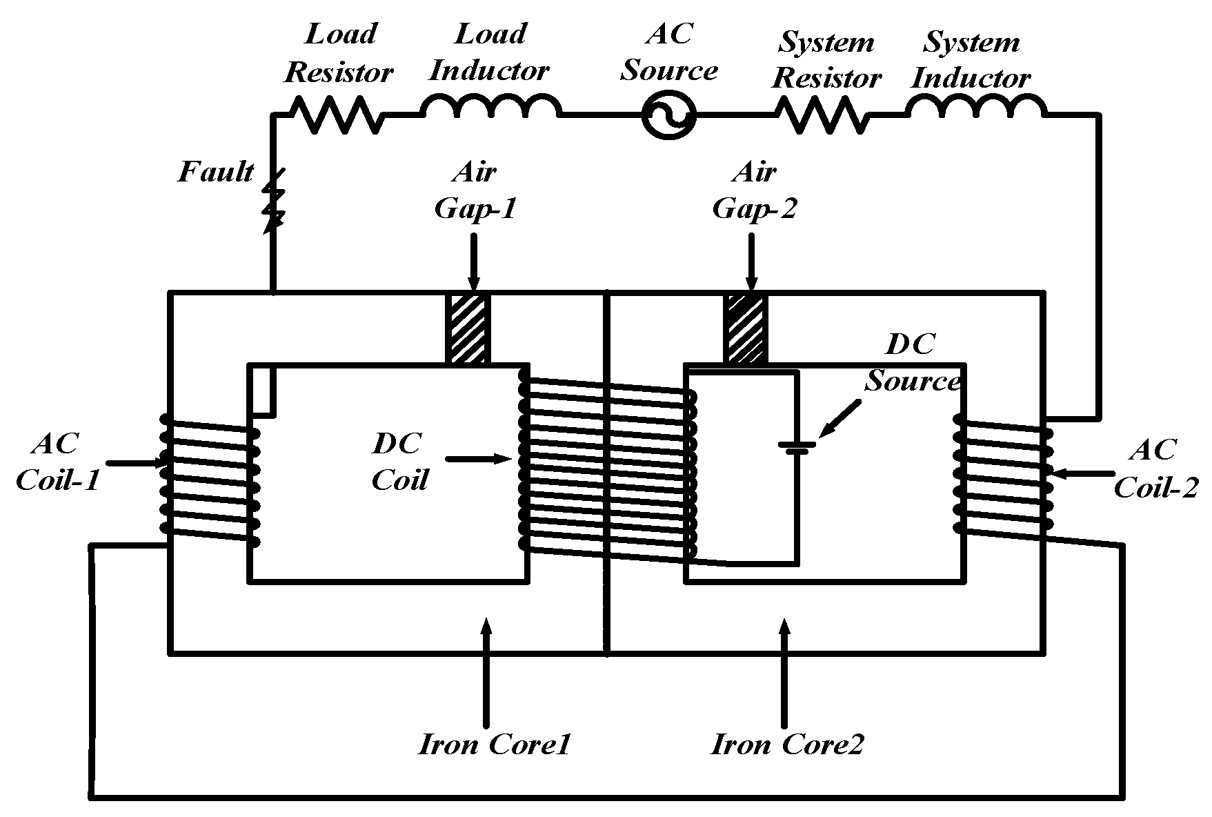
Owing to the growing demand for the power capacity of electronic systems, the existence of short-circuit current in the power equipment connected to a grid has become a major safety concern [1,2,3]. Superconducting fault current limiters are widely used to limit fault current [4,5,6,7], but the high cost of superconducting materials and difficulty of converting the superconducting state to the normal one significantly limits their development. The saturated-core fault current limiter (SFCL) (Figure 1) is a new type of alternating current (AC) reactor demonstrating low impedance during normal operation and high impedance when a fault occurs. However, it should be noted that the existing SFCL structure has two major drawbacks: Relatively high demand for direct current (DC) power and leakage reactance in the normal state.
The influence of the SFCL on the relay protection (including over-current protection [8], line distance protection [9], and zero-sequence current protection [10]) of power systems has been discussed by other researchers. SFCL prototypes connected to a grid and rated at 35,200 and 500 kV have been examined in previous studies [11,12,13]. Permanent magnet (PM)-biased SFCLs are employed to generate magneto motive force (MMF) that saturates the core in the normal state [14,15]. However, these PM-biased SFCLs cannot eliminate the influence of the PM on the core saturation after the demagnetization of the DC coil. Various SFCLs with open magnetic cores and relatively small sizes and weights have been investigated [16,17]. However, their DC biasing sources consume more power as compared to those of the SFCLs with closed cores. Several approaches are proposed to resolve this issue [18,19,20,21]: Varying the simulation time-step based on the voltage [18]; analyzing the SFCL leakage magnetic flux [19]; and decoupling the electric and magnetic data to convert the three-dimensional model into a simplified two-dimensional one [20,21]. However, none of them provides a suitable method for improving the SFCL structure. By introducing additional impedance, the current limiting capacity of the SFCL at a fault time can be increased [22,23]. Thus, a bridge-type fault current limiter (FCL)with improved dynamic performance and functionality similar to that of the SFCL has been proposed [24,25,26]; however, it exhibits low adaptability at different fault conditions. By varying the air gap, the FCL can be switched from the normal state to the limiting one [27], but this process may take relatively long time. Hence, a new structure of the AC coils is proposed to reduce the volume of the core, which has little effects on the two-phase-to-ground and three-phase-to-ground faults [28].
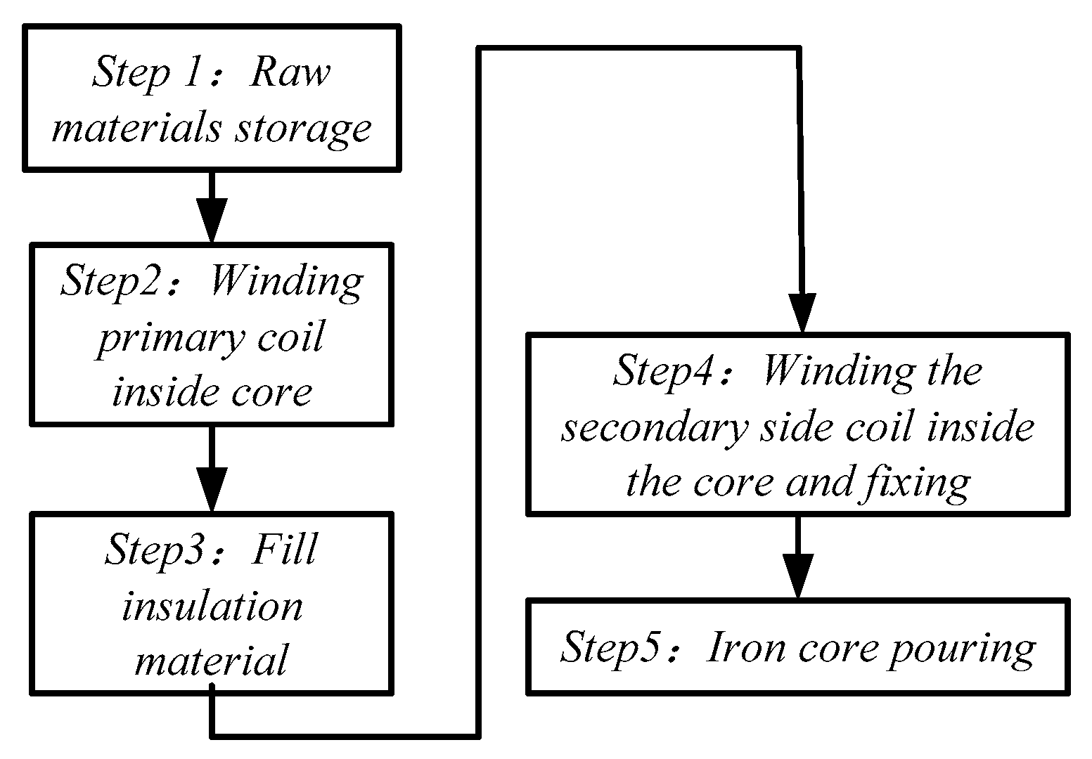
In this work, a new close-coupled three-phase SFCL(CTSFCL), in which the DC and AC coils are wound on the same core to reduce the leakage reactance in the normal state and demand for the MMF generated by a DC source, is developed. The integration process of CTSFCL is shown in Figure 2.
Two different techniques are used to compare the leakage reactance values of the regular SFCL and CTSFCL structures. By performing finite-element simulations with JMAG software and using a magnetic field division method, the superior current limiting ability of the proposed structure is verified under different short-circuit fault conditions. At the same time, the saturation of the CTSFCL cores is examined while varying the superimposed AC and DC sinusoidal fluxes in a fault situation, which strongly affects the CTSFCL impedance. In addition, the relationship between the impedance and DC excitation at different air gaps is analyzed to improve the dynamic performance of the current limiter. Finally, a prototype of the proposed FCL is fabricated, whose experimental parameters are consistent with the results of theoretical analysis.
2. Structure and Operational Principle of CTSFCL
2.1. Leakage Magnetic Flux
Figure 3a,b shows the schematic diagrams of the CTSFCL and SFCL, respectively. In both cases, six AC coils are wound on the inner limbs of six identical iron-cores. The DC coils are wound on the same iron cores outside the AC coils, as shown in Figure 3. Unlike the CTSFCL, the conventional SFCL DC coil is still wound on the inner iron cores, but the six SFCL AC coils are wound on the outer iron cores that are different from that of the DC coil.
Since the three phases of the CTSFCL and SFCL are symmetrical, the six iron cores with the same parameters are independent from each other. As the CTSFCL and SFCL can be considered three separate single-phase systems, both the single-phase SFCL (CSFCL) and regular SFCL are analyzed in this study.
To facilitate the description of the operation principles of the SFCL and CTSFCL, the main symbols and definitions utilized in this paper are listed in Table 1.
The effect of magnetic flux leakage on the two structures makes their inductances different. The magnetic field division method described in Reference [18] is utilized to further analyze this phenomenon.
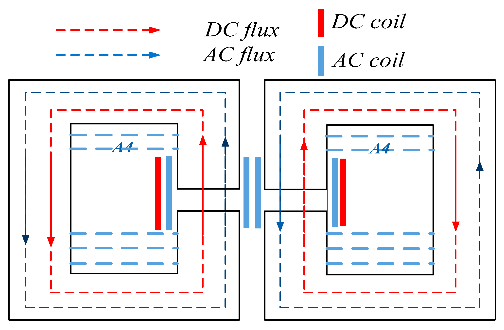
The magnetic field distributions of the CSFCL are shown in Figure 4. The magnetic flux leakage of the CSFCL is represented by the rectangular magnetic flux tube A4 in the iron window. The leakage conductance can be calculated by the following Formula [18]:
The magnetic field distributions of the SFCL is shown in Figure 5. The magnetic flux leakage of the SFCL can be divided into four parts: The rectangular area A4 located inside the window and the arc areasA1, A2, and A3 outside the AC coil. The conductance of these four parts can be calculated via Formulas (2)–(5):
Here, θ1 is equal to 1.58 radian, and h = ha + 2dac.
The equivalent magnetic circuit of the CSFCL is shown in Figure 6.
This circuit can be analyzed by applying Ampere’s law:
In Formula (6), G = 1/R.
Using Formula (6), it is possible to calculate the magnetic fluxes flowing through the CSFCL, as follows:
The equivalent magnetic circuit of the SFCL is shown in Figure 7.
It can be analyzed by applying Ampere’s law:
In Formula (9), G = 1/R.
Using Formula (9), it is possible to calculate the magnetic fluxes flowing through the SFCL, as follows:
Formulas (8) and (13) show that at the same AC and DC excitations, the DC component of the magnetic flux flowing through the CSFCL is apparently larger than that flowing through the SFCL. Although the AC component of the SFCL magnetic flux is greater than that of the CSFCL flux, the DC flux has a stronger impact on the core saturation during normal operation; as a result, the total flux of the CSFCL is still bigger than that of the SFCL. Furthermore, it is possible to calculate the inductances of the CSFCL by applying Faraday’s law:
The inductances of the SFCL can be calculated as follows:
In the normal state, the two cores become saturated due to the MMF generated by the DC source. The term μ0μr is related to the saturation of the limbs, and its value is relatively small. In this case, the magnitude of Gu is also small. Formulas (14) and (15) show that the reactance of the SFCL is larger than that of the CTSFCL (its smaller value significantly reduces the impact on the normal grid current).
When a fault occurs, one core becomes unsaturated, whereas the other core remains saturated during the first cycle. After that, the DC current decreases to a low value that cannot keep the second core in the saturated state. At this moment, both the SFCL and CSFCL exhibit the largest reactance. Meanwhile, the absolute permeability of the core μ increases; Gu becomes much larger due to core saturation, while the magnitudes of GlCSFCL, GlSFCL1, and GlSFCL2 remain unchanged, and their effect on the SFCL impedance is reduced. Therefore, during the fault period, the effect of the leakage magneto-resistance on the impedance of the SFCL is small, and the impedance values of the CTSFCL and SFCL are very close.
2.2. Air Gaps
Formulas (14) and (15) show that not only the core saturation and leakage flux, but also the air gap magneto-resistance Ro affects the inductance of the reactor:
Because the air gap is very small, the corresponding leakage flux may be considered negligible. As a result, the following formula can be derived:
Since Bδ and Bl are approximately equal, Formula (16) can be converted to Formula (18) as follows:
When the core has an air gap, its permeability is reduced by a factor of (1 + μrδ/l). Since the field strength H is inversely proportional to permeability, the magnetic flux density B remains the same when H increases by a factor of (1 + μrδ/l). As a result, the absolute permeability μ and relative permeability μr of the iron core are reduced. The air gap in the core increases the magneto-resistance of the core that prevents its saturation due to the excessive AC current under limiting conditions. However, Formula (14) shows that the magneto-resistance of the air gap increases, which reduces the CTSFCL impedance without current limiting.
In order to analyze the effect of different air gaps on the impedance variation of the CTSFCL under AC and DC flux linkages, three models with different airgap types are considered.
As shown in Figure 8a, the full air gap is very common; the wedge-type air gap depicted in panel (b) can smooth the varying magnetic permeability by changing the cut angle α; and the graded air gap (Figure 8c) can achieve a similar effect by changing the width and height of the ladder. In this study, three models of different air-gaps are constructed using JMAG software, and the relationship between the CTSFCL reactance and DC current is analyzed when the AC excitation current remains unchanged and the DC excitation current decreases. The obtained results are provided below.
2.3. Control Principle of the DC Power Supply
As shown in Figure 9, the DC power supply [29] is composed of three parts. The first part outputs DC power using two AC power sources with different voltage input sand a rectifier. The second part is a fault detection module, which determines whether the system has a short circuit fault or not. The third part is a control system, which is used to control the processes of charging and discharging the DC excitation coil.
The operation process of the DC power supply consists of the following three stages:
- When the CTSFCL is put into operation for the first time, AC2 does not supply power, and AC1 supplies power to the system and charges the DC excitation coil to a high voltage of about 1000 V. At the same time, the control system adjusts the output current of the DC power supply to the DC coil through hysteresis control to stabilize its value at 40 A.
- When the DC current is stabilized at 40 A, AC1 is switched off, whileAC2 is switched on to supply the DC excitation coil with a low voltage of approximately50 V. The supply current of the DC excitation coil remains stable at 40 A.
- When the fault signal is received, the IGBT transistor is immediately switched off, and the DC excitation coil is discharged through ZnO1. As a result, high voltage is generated, whileZnO2 is used to protect IGBT from possible damage.
3. Simulation Results
3.1. Saturation in the Normal State
In order to determine the CTSFCL reactance, a 10-kV/200-kVA CTSFCL was designed (its parameters are listed in Table 2).
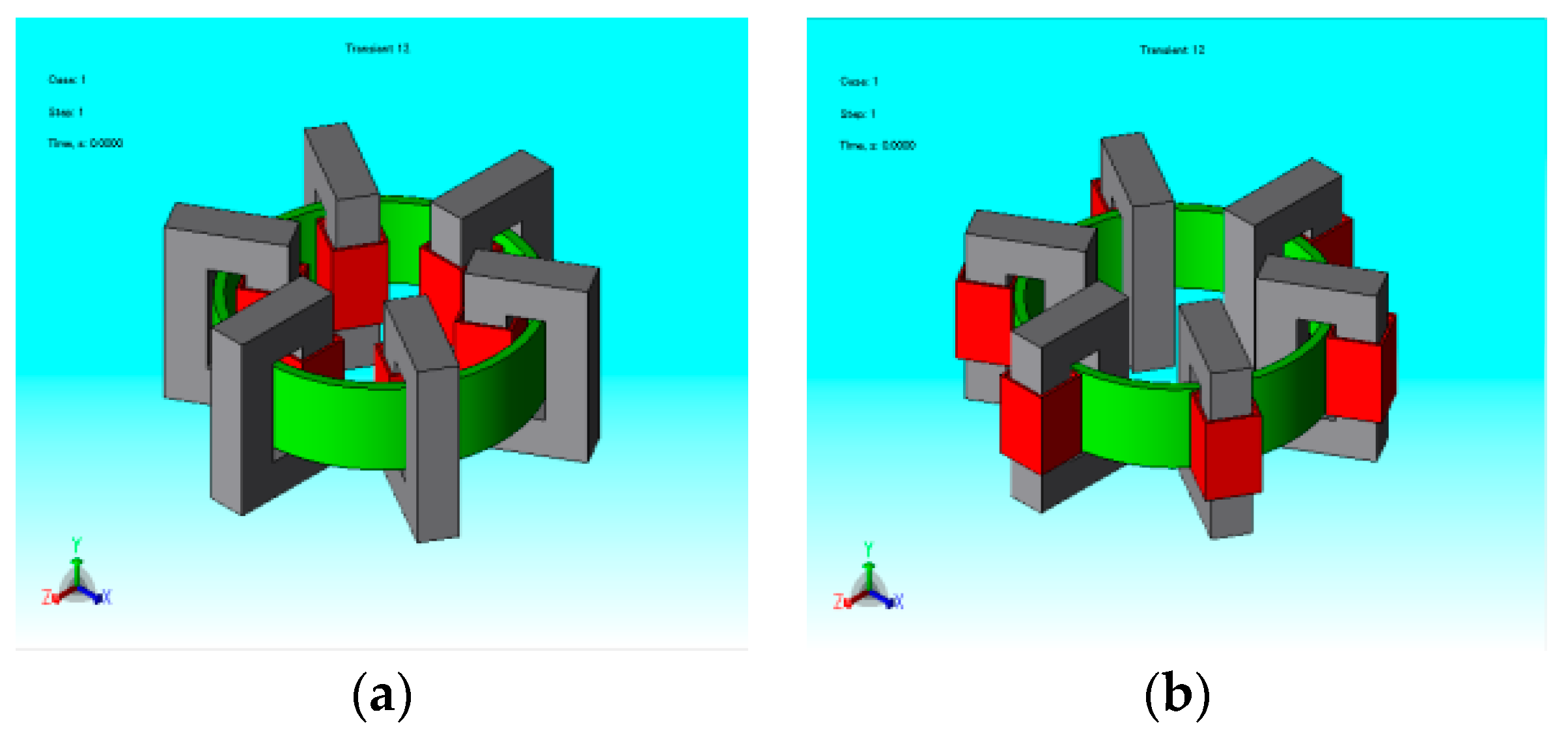
According to Table 2, two 10-kV models were obtained in JMAG software for finite element analysis (Figure 10).
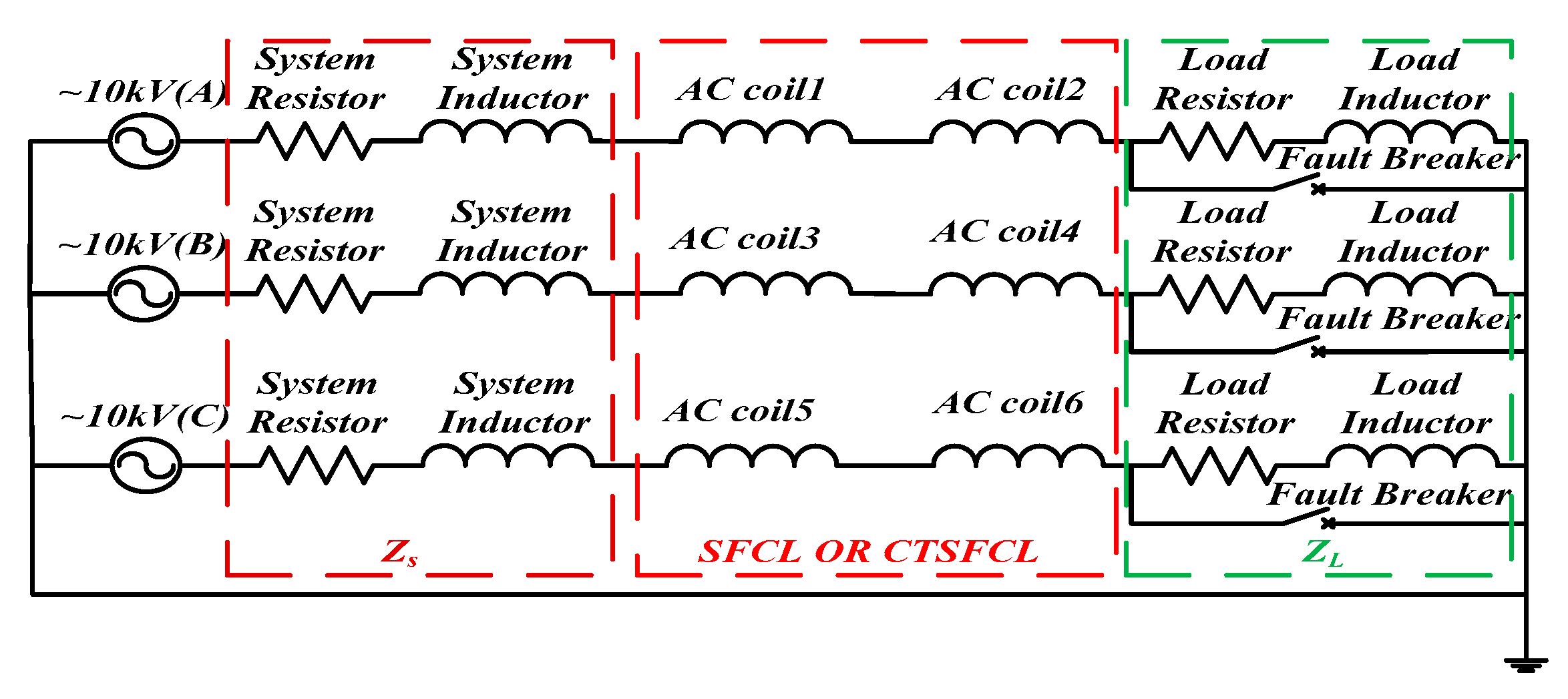
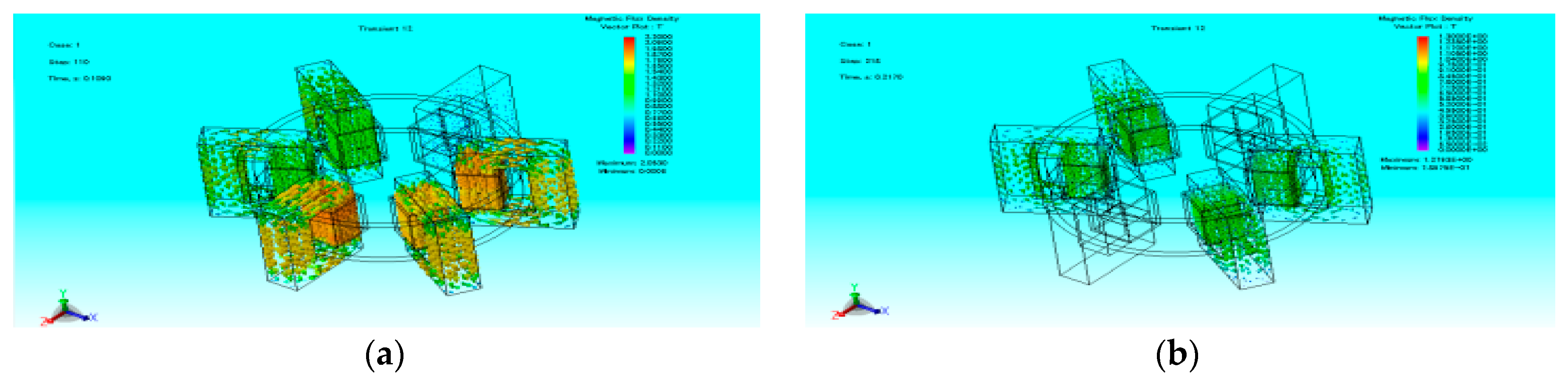
The schematic diagram of the simulation experiment is shown in Figure 11. The rated voltage of the three-phase power source is 10 kV, and the system and load impedances are equal to Zsi = 1.5 + j183.78 and ZLi = 126 + j896.92 Ω (i = A, B, C), respectively. Between 0 and 0.1 s, both AC cores of the two structures become saturated under the action of the magnetomotive force generated by the DC source, as shown in Figure 12. Due to the interaction of the DC and AC fluxes, the magnetic flux intensity curves of the two structures are sinusoidal. However, it is clear that the magnetic flux density of the CTSFCL is higher than that of the SFCL containing the same DC and AC sources, which indicates that the saturation of the former system is higher than that of the latter.
For the SFCL, a part the DC magnetic flux flows in air when it passes through the coils. Therefore, the outer limbs remain unsaturated while the inner limbs reach the saturated state, which affects the SFCL impedance in the normal state. In the CTSFCL, the AC and DC coils are wound on the same limbs, which, therefore, can be saturated at the same time. Compared with the SFCL, this new structure exhibits low demand for the DC bias source.
3.2. Impact on the Grid
In order to better analyze the reactance of the two saturated structures, during the period of 0.1–0.2 s, the DC excitation remains unchanged, the fault breaker is switched off, the load is short-circuited, and the related AC currents are compared as follows:
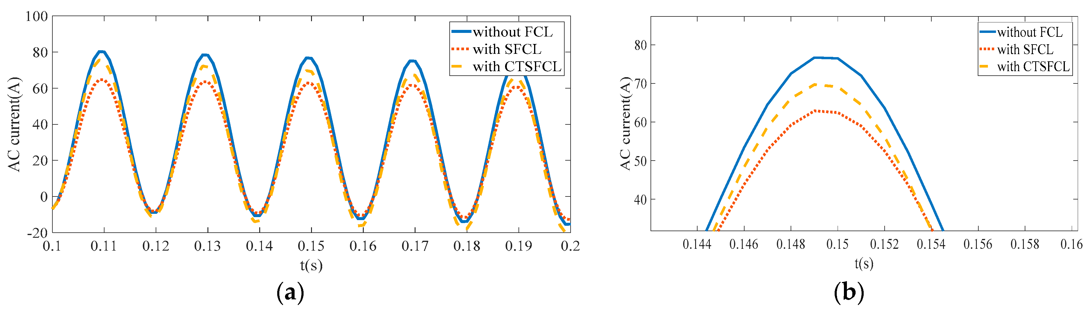
As shown in Figure 13, between 0.1 and 0.2 s, two models are saturated due to the magnetomotive force generated by the DC source. The blue, red, and yellow curves represent the AC saturated currents obtained without an FCL, with an SFCL, and with a CTSFCL, respectively. The corresponding root mean square (RMS) AC currents are equal to 31.46, 25.81, and 30.76 A, respectively. Therefore, the CTSFCL has an in significant current limiting effect on the normal current (only 2.22%), while for the SFCL, its value is more than eight times greater (18.0%). Hence, it can be concluded that the proposed structure can significantly reduce the influence of magnetic flux leakage on the normal grid current.
3.3. Current Limiting Capability
In order to verify the current limiting capabilities of the CTSFCL and SFCL, the DC current is cut off between 0.12 and 0.22 s to make both structures of the current limiters unsaturated. As shown in Figure 14, the blue, red, and yellow curves represent the AC currents obtained without an FCL, with an SFCL, and with a CTSFCL, respectively. The corresponding RMSAC currents are equal to 31.47, 9.72, and 10.07 A, respectively. The CTSFCL’s capability of current limiting is 31.99%, and that of SFCL is equal to 30.89%. Thus, as stated in Section 2.1, the CTSFCL’s capability of current limiting is reduced by a certain degree (96%) with respect to that of the SFCL, which is considered not very large. However, the traditional structure’s capacity of current limiting is eight times of that of the new structure in the normal state which will definitely has a significant influence on the normal operation of the grid. Considering this problem, the slight reduction of the current limiting capacity of the new structure is acceptable.
3.4. DC Control
When the fault signal is received, the DC coil is quickly de-energized through ZnO1, which reduces the current in the coil to exit the core saturation state, as shown in Figure 15a. After receiving the fault signal, the DC current cannot achieve complete demagnetization during the first cycle. At this time, only three of the six cores can become unsaturated, and the other three cores remain saturated. In the subsequent cycles (Figure 15b), the energy of the DC coil is completely consumed by the energy release loop. At this stage, the DC current is almost reduced to zero, and the core does not become saturated under the action of a single AC current flux linkage; as result, the six cores remain in an unsaturated state. At this time, the reactance of the limiter is maximized.
3.5. Impedancesof Different Air-Gaps
In Section 2.2, it is shown that the energy required for the CTSFCL to reach saturation depends on the air gap type and that the reactance under the current limiting conditions varies as well. Because the AC and DC coils of the CTSFCL are wound on the same core, its saturation is determined by the linkages of the AC and DC fluxes. In order to analyze the dependence of the impedance of the iron cores on the air-gap type under the action of the AC and DC flux linkages, four models with the same AC and time-stepped DC currents are constructed in JMAG (three of them contain different air-gaps, and the fourth one does not have an air gap). The parameters of their prototypes are listed in Table 2, and the values of Idc are determined by the following formula:
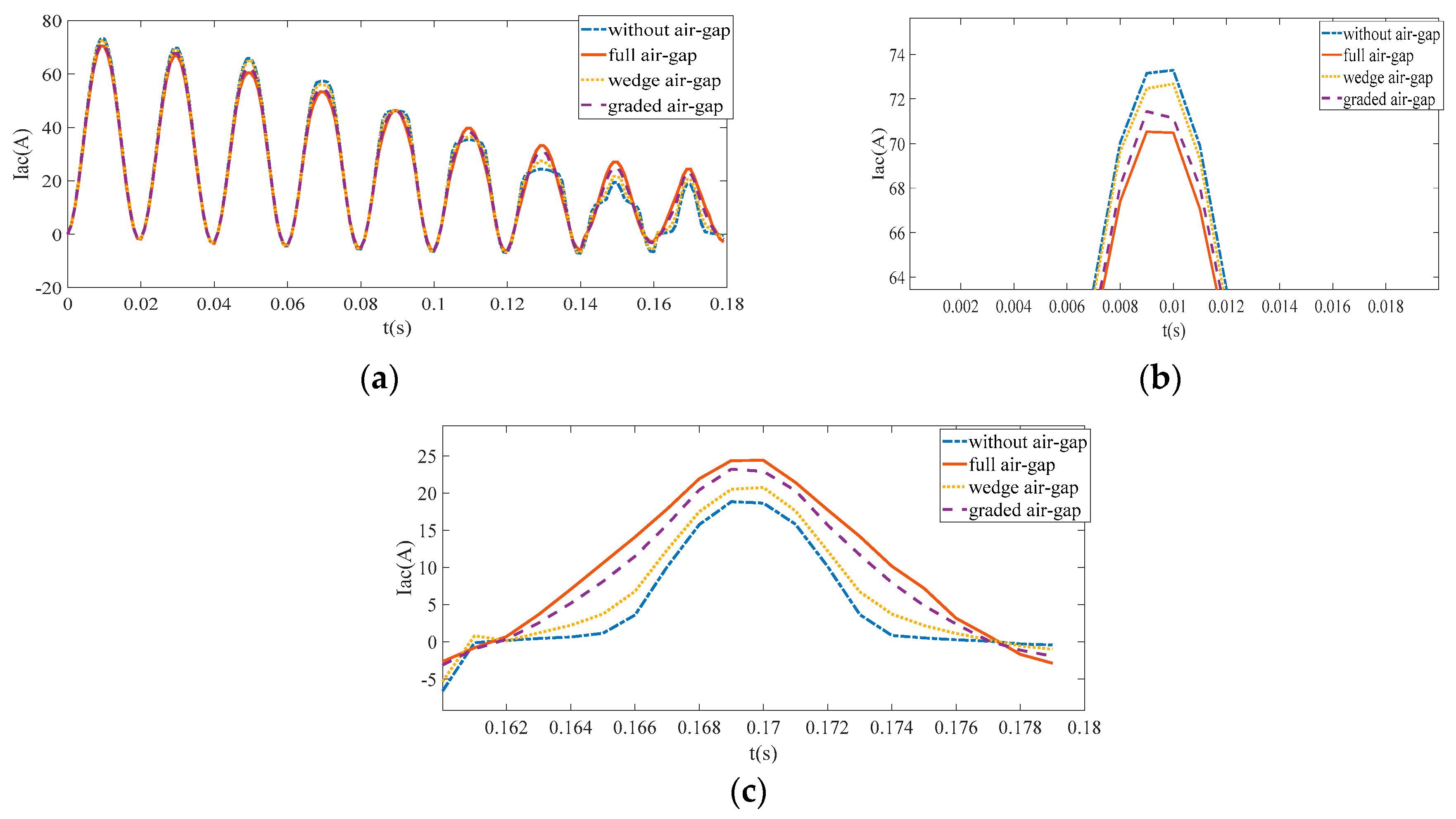
When the DC current is 40 A (Figure 16b), the AC current reaches maximum in the absence of the air gap because it is easier to achieve saturation in this configuration. Therefore, under the same DC current conditions, the saturation of the CTSFCL without an air gap is higher, the reactance is smaller, and the impact on the system is lower. When the DC current is 0 A (Figure 16c), the AC current without an air gap is smaller, and the current limiting ability of the system is stronger because the introduction of an air gap decreases the reactance of the core; therefore, the current limiting effect without an air gap is stronger than that with an air gap in an unsaturated state. As indicated by the current curves obtained for the four structures (Figure 16c), the iron cores without air-gaps will become saturated if the AC current continues to increase since it is easier to reach saturation without an air gap than with an air gap. However, different results may be obtained with an increase in the AC current.
4. Experimental Results
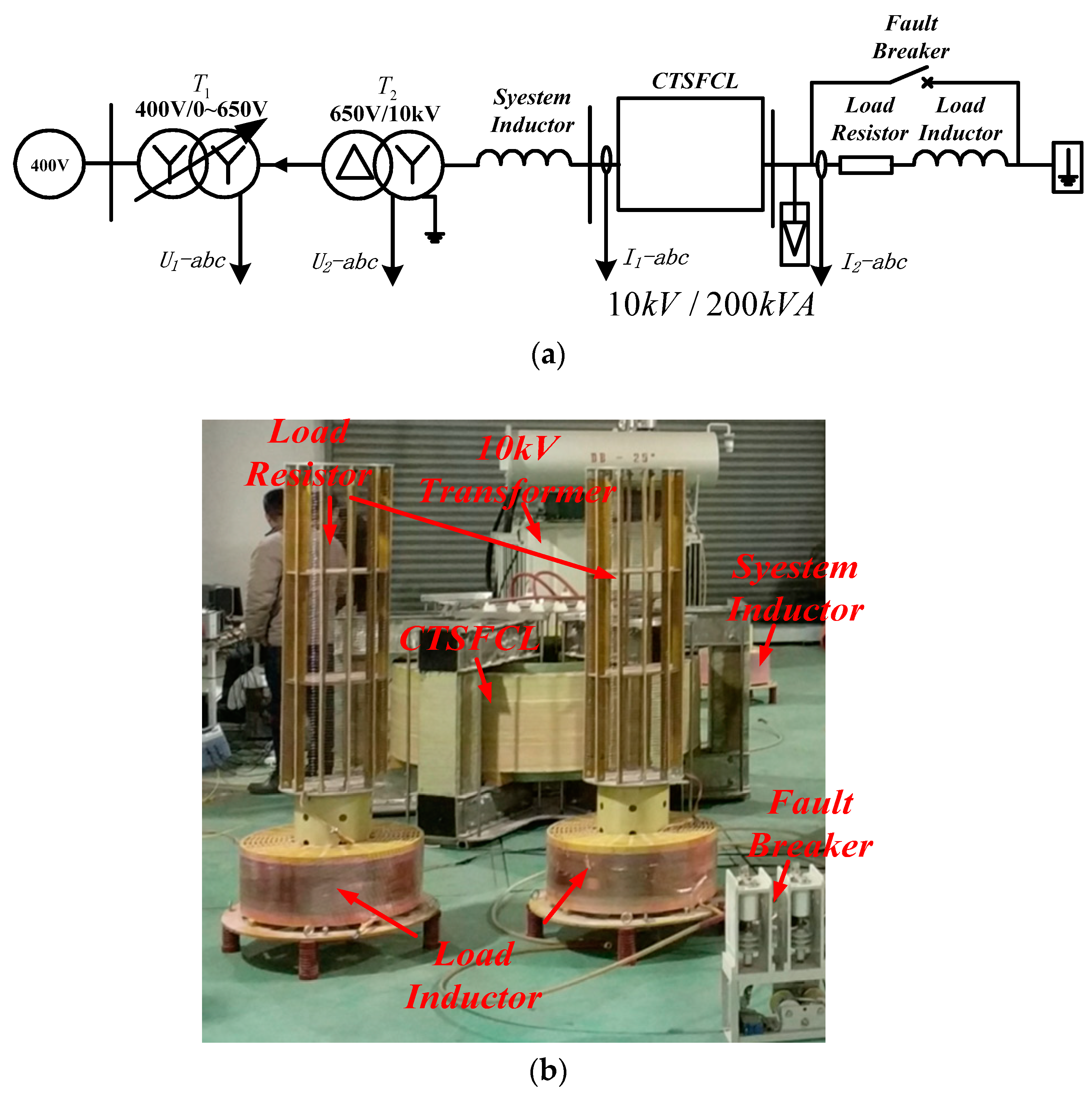
In order to verify the CTSFCL capability of current limiting and minimizing steady-state losses, a physical experiment has been conducted (Figure 17). The rated voltage of the three-phase power source is 10 kV, and the system and load impedances are equal to Zsi = j183.78 and ZLi = 126 + j896.92 Ω (I = A, B, C), respectively. The experiment simulates multiple short-circuit faults by short-circuiting the load through the fault circuit breaker.
4.1. Normal State
The normal current under the experimental conditions is about 5 A. In order to estimate the CTSFCL steady-state loss, the DC resistance and CTSFCL active loss are monitored during normal operation. DC resistance of AC coils as shown in Table 3. The results presented in Table 4 show that the voltage on the AC winding of the CTSFCL is 0.1104 kV, corresponding to only 1.9% of the total voltage, which has little effect on the entire system. The active power of the AC winding is 0.1496 kW, which is only about 0.07% of the total capacity of the prototype.
Figure 18 shows the waveform of the DC current. The green curve represents the DC voltage, and the top blue one denotes the DC current. When the system is working normally, the DC current source provides a lower voltage of about 50 V (a stable 40-A DC can be output due to hysteresis). The approximate loss on the coil is 2 kW, which is about 1% of the total capacity of the prototype equal to 200 kVA. Therefore, the DC loss of this structure can be considered relatively small.
4.2. Fault Status
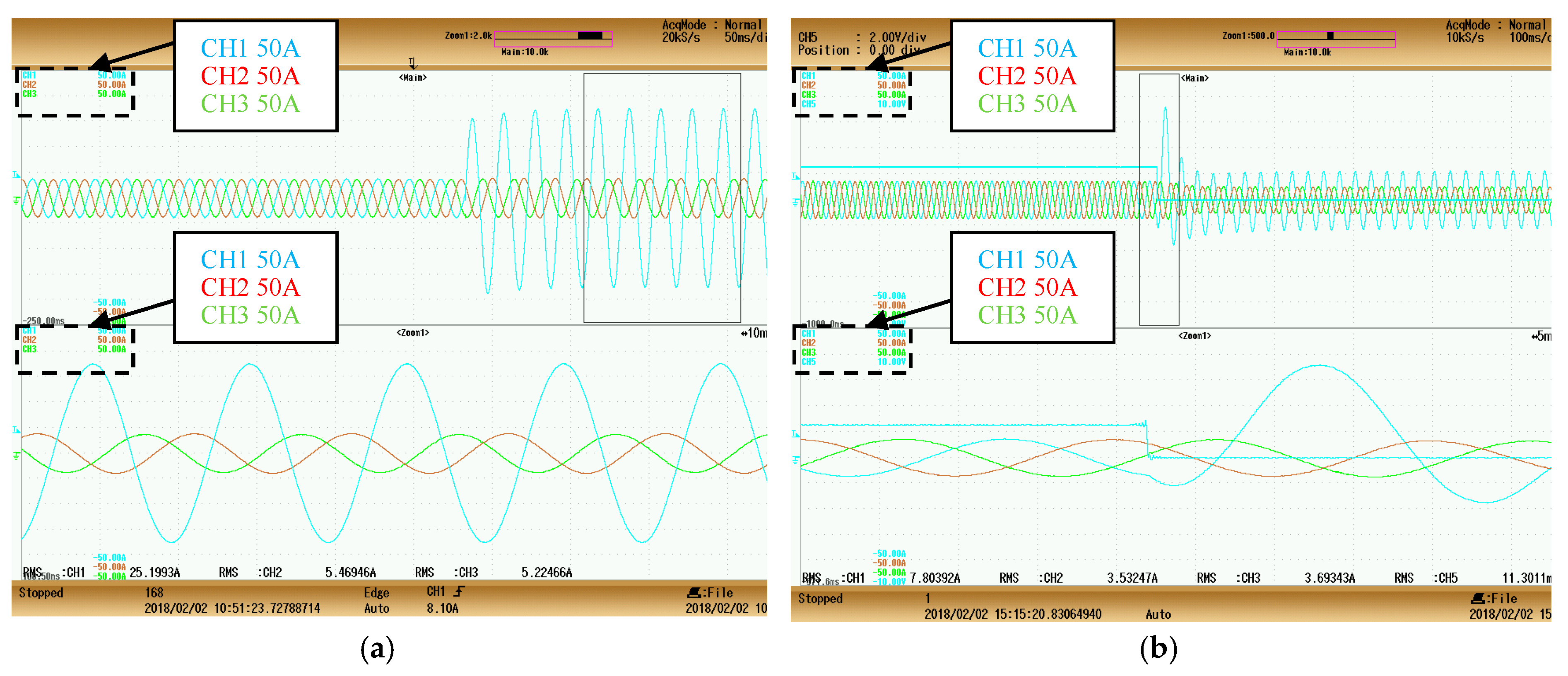
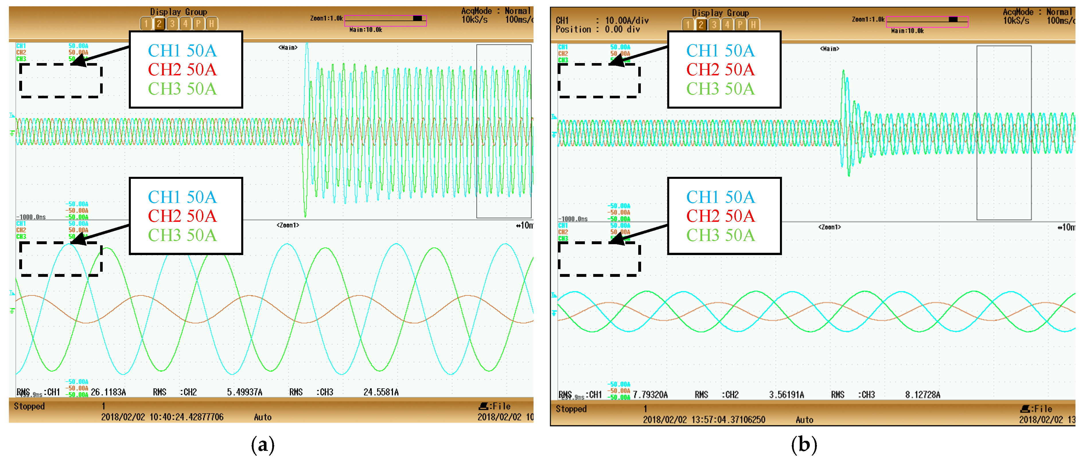
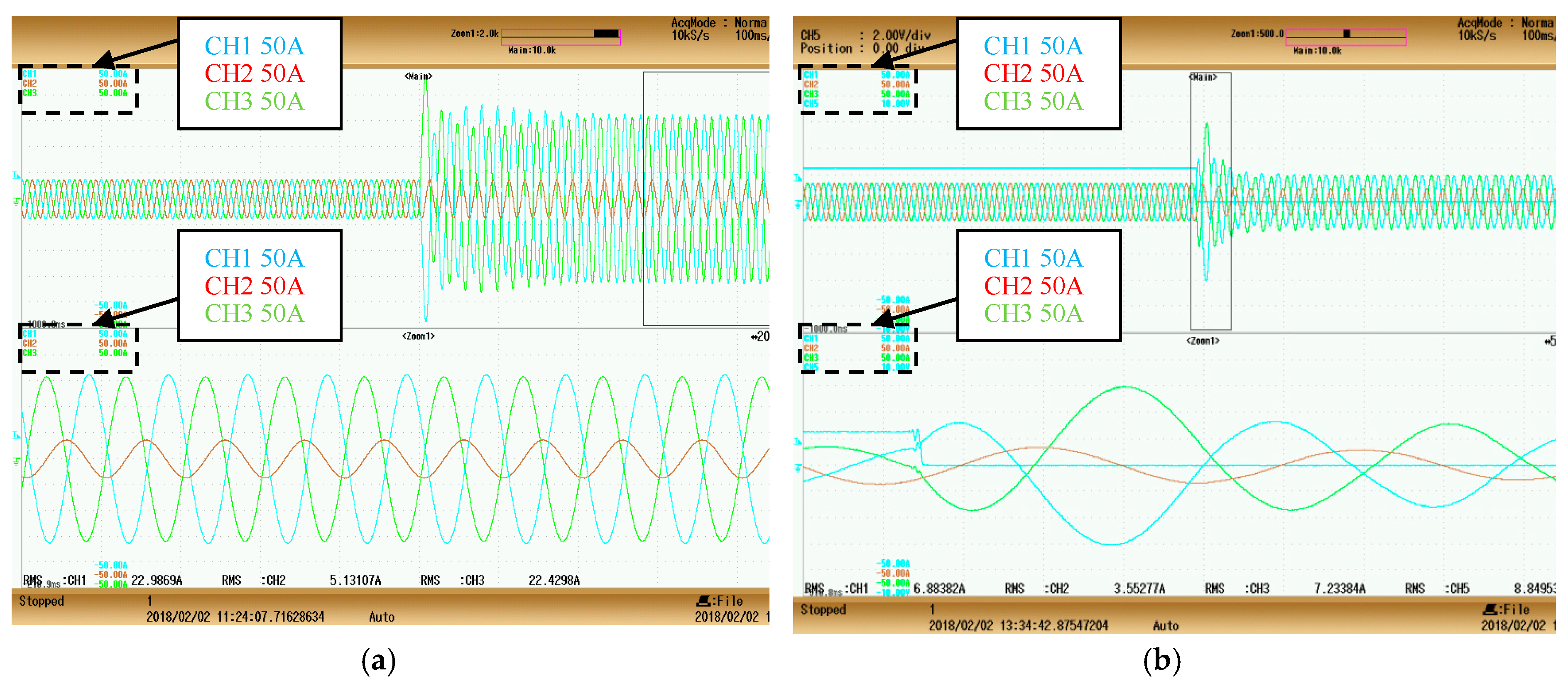
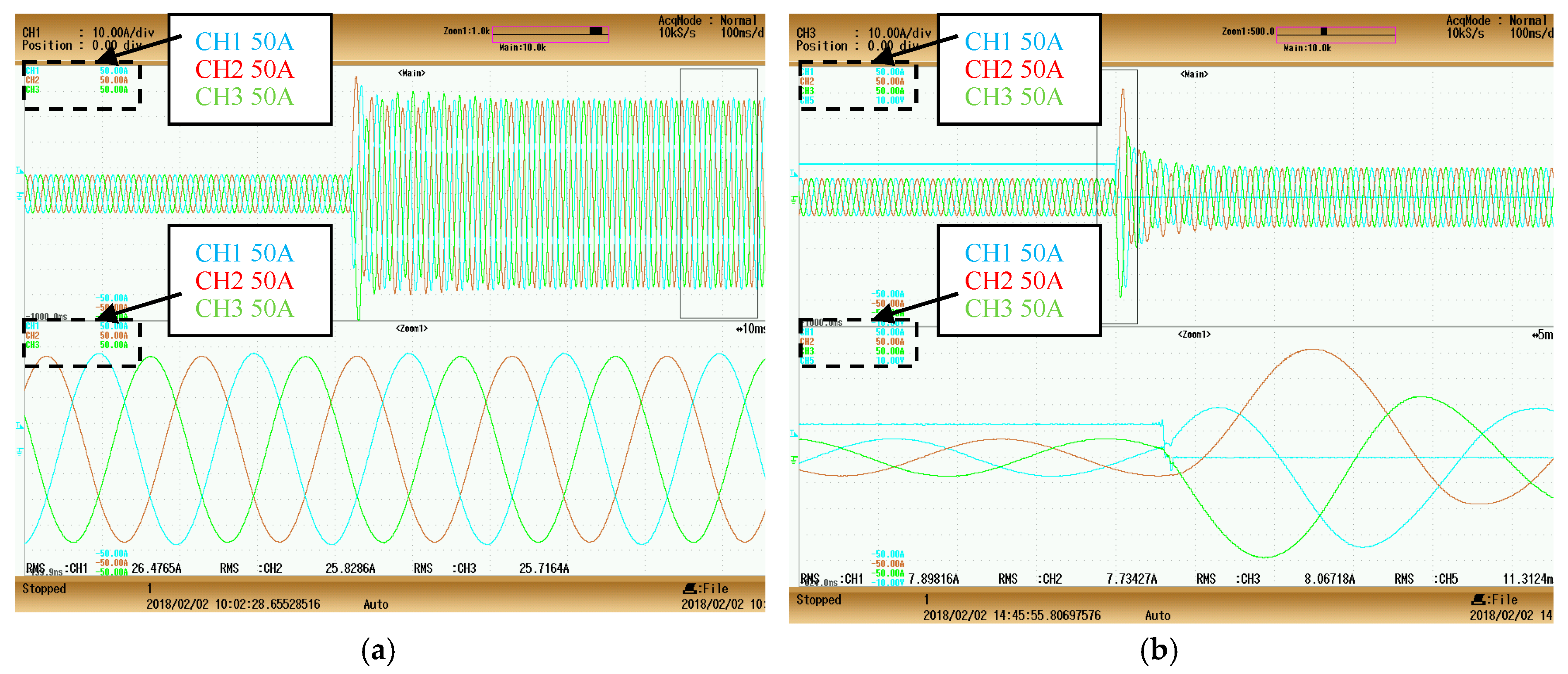
When a fault occurs, the inner limbs are no longer in the saturation state while the DC current decreases. Figure 19, Figure 20, Figure 21 and Figure 22 show the AC fault waveforms of the CTSFCL obtained for the single-phase grounding, two-phase grounding, phase-to-phase, and three-phase grounding short circuits. Channels 1, 2, and 3 correspond to the AC currents of phases A, B, and C, respectively. From the results presented in Table 5, Table 6, Table 7 and Table 8, it can be concluded that the CTSFCL can effectively limit the short-circuit current to about 30% of the original value under various conditions.
In this section, the ratio of the DC power to the capacity of the current limiter prototype and its impedances in the limiting and normal states are measured experimentally. Both the DC power and impedance of the fabricated prototype are much higher than the values reported in Reference [30] for the conventional SFCL (see Table 9).
5. Conclusions
In this study, a new type of the three-phase SFCL, in which the DC and AC coils are wound on the same core to reduce the leakage magnetic reluctance, is proposed. This structure facilitates the saturation of the core in the normal state and reduces the demand for DC power. In addition, the reactance of the limiter decreases upon saturation, which reduces its effect on the normal grid operation.
The analysis of the equivalent magnetic circuit diagrams of the SFCL and CSFCL shows that the reactance of the limier is related to the magnetic flux leakage, presence of air-gaps, and saturation of the core. The SFCL leakage magnetic flux is divided into four parts using the magnetic field division method. By comparing the leakage magnetic fields of the conventional SFCL and CTSFCL whose AC and DC coils are wound on the same core column (tightly coupled), it is found that the conductance of the leakage magnetic flux of the new structure is relatively small indicating that the novel structure proposed in this paper can convert into saturated under lower DC power supply. The structures of both current limiters are modeled in JMAG. A comparison of their saturations and AC currents measured under the same conditions shows that the new structure reduces the demand for DC power and has less influence on the grid. Furthermore, the impedances of the CTSFCL with different air-gaps have been measured as well. It is found that the structure without an air gap has the smallest impedance during saturation and largest average impedance in an unsaturated state, which is most suitable for the CTSFCL. Finally, a test prototype is fabricated to verify the proposed structure. The obtained results show that the designed structure not only has little effect on the normal current, but also exhibits high current limiting capability.
Compared with the traditional structure, the new structure proposed in this paper has the advantages of smaller demand for DC excitation during normal operation and less impact on the power grid (its normal impedance is one eighth of that of the traditional structure). The magnetic field division method and air-gap analysis described in this work can be further utilized in research studies on the iron core reactor. However, the current limiting impedance is slightly reduced compared with the original value, and the insulation problems caused by shortening the distance between the AC and DC coils must be addressed in future works.
Author Contributions
This article has four authors: Haocong Shen and J.Z. conceived and designed the research method; Haocong Shen, F.M., Haoyuan Sha and C.S. performed the experiments; Haocong Shen and Haoyuan Sha analyzed the data, and Haocong Shen wrote the manuscript.
Funding
This research received no external funding.
Conflicts of Interest
The authors declare no conflict of interest.
References
- Kies, A.; Schyska, B.U.; von Bremen, L. Curtailment in a highly renewable power system and its effect on capacity factors. Energies 2016, 9, 510. [Google Scholar] [CrossRef]
- Sun, X.; Zhang, B.; Tang, X.; McLellan, B.C.; Höök, M. Sustainable Energy Transitions in China: Renewable Options and Impacts on the Electricity System. Energies 2016, 9, 980. [Google Scholar] [CrossRef]
- Lu, J.; Wang, W.; Zhang, Y.; Cheng, S. Multi-Objective Optimization of Hybrid Renewable Energy System Using an Enhanced Multi-Objective Evolutionary Algorithm. Energies 2017, 10, 674. [Google Scholar]
- Chen, L.; Chen, H.; Yang, J.; Yu, Y.; Zhen, K.; Liu, Y.; Ren, L. Coordinated Control of Superconducting Fault Current Limiter and Superconducting Magnetic Energy Storage for Transient Performance Enhancement of Grid-Connected Photovoltaic Generation System. Energies 2017, 10, 56. [Google Scholar] [CrossRef]
- Xue, S.; Gao, F.; Sun, W.; Li, B. Protection Principle for a DC distribution system with a resistive superconductive fault current limiter. Energies 2015, 8, 4839–4852. [Google Scholar] [CrossRef]
- Oliveira, F.; Amorim, A.; Encarnação, L.; Fardin, J.; Orlando, M.; Silva, S.; Simonetti, D. Enhancing LVRT of DFIG by using a superconducting current limiter on rotor circuit. Energies 2016, 9, 16. [Google Scholar] [CrossRef]
- Chen, L.; Tu, X.; Chen, H.; Yang, J.; Wu, Y.; Shu, X.; Ren, L. Technical Evaluation of Superconducting Fault Current Limiters Used in a Micro-Grid by Considering the Fault Characteristics of Distributed Generation, Energy Storage and Power Loads. Energies 2016, 9, 769. [Google Scholar] [CrossRef]
- Li, B.; Li, C.; Guo, F.; Xin, Y. Overcurrent protection coordination in a power distribution network with the active superconductive fault current limiter. IEEE Trans. Appl. Superconduct. 2014, 24, 1–4. [Google Scholar]
- Li, B.; Li, C.; Guo, F. Application studies on the active sisfcl in electric transmission system and its impact on line distance protection. IEEE Trans. Appl. Superconduct. 2015, 25, 1–9. [Google Scholar] [CrossRef]
- Li, B.; Li, C.; Guo, F.; Xin, Y.; Wang, C.; Pang, X. Coordination of superconductive fault current limiters with zero-sequence current protection of transmission lines. IEEE Trans. Appl. Superconduct. 2014, 24, 1–5. [Google Scholar]
- Xin, Y.; Gong, W.Z.; Niu, X.Y.; Gao, Y.Q.; Guo, Q.Q.; Xiao, L.X.; Cao, Z.J.; Hong, H.; Wu, A.G.; Li, Z.H.; et al. Manufacturing and test of a 35 kV/90 MVA saturated iron-core type superconductive fault current limiter for live-grid operation. IEEE Trans. Appl. Supercond. 2009, 19, 1934–1937. [Google Scholar] [CrossRef]
- Xin, Y.; Gong, W.Z.; Hong, H.; Gao, Y.Q.; Niu, X.Y.; Zhang, J.Y.; Sun, Y.W.; Ren, A.L.; Wang, H.Z.; Zhang, L.F.; et al. Development of a 220 kV/300 MVA superconductive fault current limiter. Supercond. Sci. Technol. 2012, 25, 105011. [Google Scholar] [CrossRef]
- Wei, Z.; Xin, Y.; Jin, J.; Li, Q. Optimized design of coils and iron cores for a saturated iron core superconducting fault current limiter. IEEE Trans. Appl. Supercond. 2016, 26, 1–4. [Google Scholar] [CrossRef]
- Yuan, J.; Zhong, Y.; Wei, L.; Liao, S.; Gao, Y.; Muramatsu, K.; Chen, B. A novel three-phase compact saturated-core fault current limiter. IEEE Trans. Magn. 2017, 53, 1–2. [Google Scholar]
- Yuan, J.; Zhong, Y.; Lei, Y.; Tian, C.; Guan, W.; Gao, Y.; Muramatsu, K.; Chen, B. A novel hybrid saturated core fault current limiter topology considering permanent magnet stability and performance. IEEE Trans. Magn. 2017, 53, 1–4. [Google Scholar] [CrossRef]
- Pellecchia, A.; Klaus, D.; Masullo, G.; Marabotto, R.; Morandi, A.; Fabbri, M.; Goodhand, C.; Helm, J. Development of a saturated core fault current limiter with open magnetic cores and magnesium diboride saturating coils. IEEE Trans. Appl. Supercond. 2017, 27, 1–7. [Google Scholar] [CrossRef]
- Knott, J.C.; Moscrop, J.W. Increasing energy efficiency of saturated-core fault current limiters with permanent magnets. IEEE Trans. Magn. 2013, 49, 4132–4136. [Google Scholar] [CrossRef]
- Jia, Y.; Yuan, J.; Shi, Z.; Zhu, H.; Geng, Y.; Zou, J. Simulation method for current-limiting effect of saturated-core superconducting fault current limiter. IEEE Trans. Appl. Supercond. 2016, 26, 1–4. [Google Scholar] [CrossRef]
- Zhang, C.; Tang, Y.; Xu, Y.; Ren, L.; Wang, Z.; Liang, S. Analysis of magnetic circuit and leakage magnetic field of a saturated iron-core superconducting fault current limiter. IEEE Trans. Appl. Supercond. 2017, 27, 1–5. [Google Scholar] [CrossRef]
- Jia, Y.; Ainslie, M.D.; Hu, D.; Yuan, J. Numerical simulation and analysis of a saturated-core-type superconducting fault current limiter. IEEE Trans. Appl. Supercond. 2017, 27, 1–5. [Google Scholar] [CrossRef]
- Belov, A.; Belyakov, V.; Belyakova, T.; Bondarenko, V.; Firsov, A.; Hon, A.; Kaparkova, M.; Krylova, N.; Kukhtin, V.; Lamzin, E.; et al. Computational technique for analysis of superconductive fault current limiters with saturated core. IEEE Trans. Appl. Supercond. 2014, 24, 1–5. [Google Scholar] [CrossRef]
- Zhang, W.; Hu, X.; Zhou, H.; Wang, S.; Liu, D.; Zhu, Y. Experimental research on an improved saturated core high temperature superconducting fault current limiter. Trans. China Electrotech. Soc. 2014, 29, 169–176. [Google Scholar]
- Zhang, W.; Hu, X.; Zhou, H. Experimental research on a novel saturated core high temperature superconducting fault current limiter. Trans. China Electrotech. Soc. 2015, 35, 494–501. [Google Scholar]
- Yuan, J.; Lei, Y.; Wei, L.; Tian, C.; Chen, B.; Du, Z. A novel bridge-type hybrid saturated-core fault current limiter based on permanent magnets. IEEE Trans. Magn. 2015, 51, 1–4. [Google Scholar]
- Wei, L.; Chen, B.; Yuan, J.; Tian, C.; Zhong, Y.; Li, X.; Gao, Y.; Muramatsu, K. Performance and optimization study of a novel compact permanent-magnet-biased fault current limiter. IEEE Trans. Magn. 2017, 53, 1–4. [Google Scholar] [CrossRef]
- Wei, L.; Chen, B.; Liu, Y.; Tian, C.; Yuan, J.; Bu, Y.; Zhu, T. Performance investigation and optimization of a novel hybrid saturated-core fault-current limiter considering the leakage effect. Energies 2018, 11, 61. [Google Scholar] [CrossRef]
- Aliabad, A.D.; Zarchi, S.H. Optimal design and analysis of a variable reactor fault current limiter. IET Electr. Power Appl. 2017, 11, 1619–1626. [Google Scholar] [CrossRef]
- Nikulshin, Y.; Wolfus, Y.; Friedman, A.; Yeshurun, Y.; Rozenshtein, V.; Landwer, D.; Garbi, U. Saturated core fault current limiters in a live grid. IEEE Trans. Appl. Supercond. 2016, 26, 1–4. [Google Scholar] [CrossRef]
- Cui, J.B.; Sun, Y.W.; Hong, H.; Niu, X.Y.; Tian, B.; Li, Q.; Zhang, J.Y.; Gong, W.Z.; Xin, Y. Study on field suppression unit in DC excitation system for saturated iron-core superconducting fault current limiter. IEEE Int. Conf. Appl. Supercond. Electromagn. Devices 2014, 24, 1–4. [Google Scholar] [CrossRef]
- Xin, Y.; Gong, W.Z.; Gao, Y.Q.; Niu, X.Y.; Guo, Q.Q.; Li, Z.H.; Hong, H.; Cao, Z.J.; Tian, B.; Wang, Y.; et al. Introduction of structure and performance of 35 kV/90 MVA. Rare Met. Mater. Eng. 2008, 37 (Suppl. S4). [Google Scholar]
Figure 1.
Schematic diagram of the SFCL.

Figure 2.
Flow chart of the integration process.

Figure 3.
(a) Schematic diagram of the CTSFCL; (b) Schematic diagram of the SFCL.

Figure 4.
Magnetic field distribution in the CSFCL.

Figure 5.
Magnetic field distribution in the SFCL.

Figure 6.
Equivalent magnetic circuit of the CSFCL.

Figure 7.
Equivalent magnetic circuit of the SFCL.

Figure 8.
(a) Full; (b) wedge-type, and (c) graded air-gaps.

Figure 9.
Schematic diagram of the DC supply.

Figure 10.
Simulation models obtained in JMAG. (a) CTSFCL; (b) SFCL.

Figure 11.
Schematic diagram of the simulation experiment.

Figure 12.
Finite element analysis of the CTSFCL and SFCL. (a) CTSFCL; (b) SFCL; (c) Magnetic flux intensities of the CTSFCL and SFCL.
Figure 12.
Finite element analysis of the CTSFCL and SFCL. (a) CTSFCL; (b) SFCL; (c) Magnetic flux intensities of the CTSFCL and SFCL.

Figure 13.
(a) AC currents flowing in the CTSFCL and SFCL; (b) Partial enlargement of the AC current.
Figure 13.
(a) AC currents flowing in the CTSFCL and SFCL; (b) Partial enlargement of the AC current.

Figure 14.
AC currents flowing in the CTSFCL and SFCL (DC = 0 A).

Figure 15.
Magnetic density of the core. (a) First cycle; (b) Subsequent cycles.

Figure 16.
(a) AC currents flowing at different air gaps; (b) Partial enlargement of the AC current (DC = 40 A); (c) Partial enlargement of the AC current (DC = 0 A).
Figure 16.
(a) AC currents flowing at different air gaps; (b) Partial enlargement of the AC current (DC = 40 A); (c) Partial enlargement of the AC current (DC = 0 A).

Figure 17.
(a) Schematic diagram of the10-kV experimental prototype; (b) A photograph of the field experiment.
Figure 17.
(a) Schematic diagram of the10-kV experimental prototype; (b) A photograph of the field experiment.

Figure 18.
DC current waveform.

Figure 19.
Single-phase-to-ground fault. (a) Without a CTSFCL; (b)with a CTSFCL.

Figure 20.
Two-phase-to-ground fault. (a) Without a CTSFCL; (b) with a CTSFCL

Figure 21.
Phase-to-phase fault. (a) Without a CTSFCL; (b) with a CTSFCL.

Figure 22.
Three-phase-to-ground fault. (a) Without a CTSFCL; (b) with a CTSFCL.


Table 1.
Symbols and definitions utilized in this work.
| Symbol | Definition | Symbol | Definition |
|---|---|---|---|
| μ0 | Permeability of vacuum | Rc1 | Reluctance of the left inner limb |
| μr | Relative permeability | Rc2 | Reluctance of the right inner limb |
| μe | Effective relative permeability | Ro | Reluctance of the air-gap |
| l | Length of the flux | Ru | Reluctance of the yoke |
| lg | Height of the AC coil | RlCSFCL | Reluctance of the leakage magnetic fluxes of the CSFCL |
| ha | Height of the window core | RlSFCL | Reluctance of the leakage magnetic fluxes of the SFCL |
| hb | Length of the window core | Gu | Conductance of the yoke |
| dac | Height of the upper and lower iron yokes | GlCSFCL | Conductance of the leakage magnetic fluxes of the CSFCL |
| N | Number of coil turns | GlSFCL | Conductance of the leakage magnetic fluxes of the SFCL |
| I | Current in coils | Φ | Magnetic flux passing through the core |
| S | Cross-sectional area of core | δ | Length of the air gap |
| HL | Field strength of the core | Hδ | Field strength of the air gap |
| Bl | Magnetic flux density of the core | Bδ | Magnetic flux density of the air-gap |
| Leq1 | Inductance of the left AC coil of the CSFCL | Leq3 | Inductance of the left AC coil of the SFCL |
| Leq2 | Inductance of the right AC coil of the CSFCL | Leq4 | Inductance of the right AC coil of the SFCL |
Table 2.
Parameters of the main components of the 10-kV/200-kVA CTSFCL.
| Component | Parameter | Value |
|---|---|---|
| Iron Cores | Material | 35JN300 |
| AC\DC limb, length | 550 mm | |
| DC limb cross-section, mm2 | 40,000 | |
| AC limb cross-section, mm2 | 40,000 | |
| AC Coil | Number of turns | 228 |
| Frequency | 50 Hz | |
| Conductor | Copper | |
| Height of AC coils | 448 mm | |
| DC Coil | Current | 40 A (rated) |
| Number of turns | 600 | |
| Height of DC coils | 448 mm |
Table 3.
DC resistances of the three-phase windings.
| RAB (Ω) | RBC (Ω) | RCA (Ω) |
|---|---|---|
| 0.5955 | 0.5930 | 0.5945 |
Table 4.
Steady-state loss of the CTFCL.
| Irated (A) | UFCL (kV) | Active loss (kW) | Pkt (kW) | Ptot (kW) |
|---|---|---|---|---|
| 5.038 | 0.1104 | 0.1303 | 0.1283 | 0.1496 |
Table 5.
Single-phase-to-ground fault.
| Parameter | Without CTSFCL | With CTSFCL | ||||
|---|---|---|---|---|---|---|
| Voltage RMS (kV) | UAB | UBC | UCA | UAB | UBC | UCA |
| 10.04 | 10.07 | 10.05 | 10.02 | 10.03 | 10.03 | |
| Fault current (A) | IA | IB | IC | IA | IB | IC |
| 25.1993 | 5.22466 | 5.46946 | 7.80392 | 3.69343 | 3.53247 | |
| Current limiting ratio (%) | - | - | - | 30.97 | 70.69 | 64.59 |
Table 6.
Two-phase-to-ground fault.
| Parameter | Without CTSFCL | With CTSFCL | ||||
|---|---|---|---|---|---|---|
| Voltage RMS (kV) | UAB | UBC | UCA | UAB | UBC | UCA |
| 10.01 | 10.03 | 10.03 | 10.02 | 10.01 | 10.02 | |
| Fault current (A) | IA | IB | IC | IA | IB | IC |
| 26.1183 | 24.5581 | 5.4994 | 7.7932 | 8.1272 | 3.5619 | |
| Current limiting ratio (%) | - | - | - | 29.84 | 33.09 | 64.77 |
Table 7.
Phase-to-phase fault.
| Parameter | Without CTSFCL | With CTSFCL | ||||
|---|---|---|---|---|---|---|
| Voltage RMS (kV) | UAB | UBC | UCA | UAB | UBC | UCA |
| 10.01 | 10.02 | 10.04 | 10.02 | 10.02 | 10.03 | |
| Fault current (A) | IA | IB | IC | IA | IB | IC |
| 22.9869 | 22.4298 | 5.13107 | 6.88382 | 7.23384 | 3.55277 | |
| Current limiting ratio (%) | - | - | - | 29.95 | 32.25 | 69.24 |
Table 8.
Three-phase-to-ground fault.
| Parameter | Without CTSFCL | With CTSFCL | ||||
|---|---|---|---|---|---|---|
| Voltage RMS (kV) | UAB | UBC | UCA | UAB | UBC | UCA |
| 10.00 | 10.02 | 10.03 | 10.03 | 10.04 | 10.05 | |
| Fault current (A) | IA | IB | IC | IA | IB | IC |
| 26.4765 | 25.7164 | 25.8286 | 7.89816 | 8.06718 | 7.73427 | |
| Current limiting ratio (%) | - | - | - | 29.83 | 31.37 | 29.94 |
Table 9.
Comparison between the SFCL and CTSFCL parameters.
| Parameter | SFCL [30] | CTSFCL |
|---|---|---|
| Capacity | 90 MVA | 200 kVA |
| DC power at normal operation | 0.982 MVA | 2 kVA |
| Ratio of DC power to capacity | 1.09% | 1% |
| Impedance at normal operation Znormal/Ω | <0.35 | <21.9 |
| Impedance at limitedConditions Zlimited/Ω | 0.896 | 500 |
| Zlimited/Znormal | 2.56 | 22.83 |
© 2018 by the authors. Licensee MDPI, Basel, Switzerland. This article is an open access article distributed under the terms and conditions of the Creative Commons Attribution (CC BY) license (http://creativecommons.org/licenses/by/4.0/).
Share and Cite
MDPI and ACS Style
Shen, H.; Mei, F.; Zheng, J.; Sha, H.; She, C. Three-Phase Saturated-Core Fault Current Limiter. Energies 2018, 11, 3471. https://doi.org/10.3390/en11123471
AMA Style
Shen H, Mei F, Zheng J, Sha H, She C. Three-Phase Saturated-Core Fault Current Limiter. Energies. 2018; 11(12):3471. https://doi.org/10.3390/en11123471
Chicago/Turabian StyleShen, Haocong, Fei Mei, Jianyong Zheng, Haoyuan Sha, and Changjia She. 2018. "Three-Phase Saturated-Core Fault Current Limiter" Energies 11, no. 12: 3471. https://doi.org/10.3390/en11123471
Note that from the first issue of 2016, this journal uses article numbers instead of page numbers. See further details here.