Neural Network of Roof Cutting Blasting Parameters Based on Mines with Different Roof Conditions


1
State Key Laboratory for Geomechanics & Deep Underground Engineering, China University of Mining & Technology, Beijing 100083, China
2
School of Mechanics and Civil Engineering, China University of Mining & Technology, Beijing 100083, China
3
School of Safety Engineering, North China Institute of Science & Technology, Hebei 065201, China
*
Author to whom correspondence should be addressed.
Energies 2018, 11(12), 3468; https://doi.org/10.3390/en11123468
Submission received: 27 October 2018
/
Revised: 25 November 2018
/
Accepted: 10 December 2018
/
Published: 11 December 2018
Abstract
:The design and construction of roof cutting and blasting is a key part of the roof cutting pressure releasing gob-side entry retaining (RCPRGER) technology. In the existing research, the blasting parameters of roof cutting have been primarily determined by field tests. However, the disadvantages of field tests include a complicated process, which hinders the succession of related procedures, and an unstable roof cutting effect. Therefore, in this work, the authors attempt to use a mathematical analysis method to simplify the design process of the key parameters of roof cutting blasting. First, the mechanics process mechanism of surrounding rocks with roof cutting and pressure releasing is investigated, and the stress evolution process of the surrounding rock is divided into the following six stages: original rock stress state, excavation stress state, supporting stress state, roof cutting stress state, premining stress state, and postmining stress state. Furthermore, the relationship between roof cutting and entry retaining from the perspective of Mohr’s stress circle is discussed. Next, using four typical mines, including the Tashan, Yuanlin, Jinfeng, and Hengyuan coal mines, as examples, the existing design methods of roof cutting and blasting, geological data characteristics of each mine, distribution rule of roof cutting connectivity rate, and explosive charge structure of roof cutting blasting are summarized. Based on these results, the logic of roof cutting blasting design is obtained, the key indices affecting blasting design are determined, and the blasting design is defined as a complex fuzzy problem with multiple factors. Finally, based on the study of the above mechanics mechanism and blasting rule, a three-layer back propagation (BP) neural network, including six input units, nine hidden units, and three output units, is developed with the four typical mines as the sample space. This neural network realizes the rapid determination of the three key parameters pertaining to sealing length, blasthole spacing, and the explosive charge weight of a single hole. Through training, the calculation error is less than 0.48%, which considerably simplifies the design process of the blasting parameters. The charge structure parameters can also be determined according to this method. At present, the construction of this neural network has the shortcomings of limited sample space. This problem can be overcome by supplementing the sample size in the subsequent research and practice, which will improve the efficiency and accuracy of this design method and promote the application and development of the RCPRGER technology. The interdisciplinary research reported in this paper is an attempt that uses an intelligent algorithm to simplify the design process of roof cutting blasting in RCPRGER, and it represents not only an application development of the intelligent algorithm, but also a new step regarding the intelligent design of RCPRGER technology.
1. Introduction
Energy is the foundation of the continuous development of the world economy and human civilization [1]. With the rapid progress of human society in the past century, sustainable development has become the common choice of mankind. Coal occupies a large proportion of the primary energy consumption; however, the initial coal mining and utilization process is harsh [2]. Although the process meets the energy supply requirement of a development stage, it is not conducive to long-term sustainable development. Therefore, at the present stage, when alternative energy has not completely replaced coal energy, on one hand, we must attempt to vigorously enhance the efficiency of alternative energy, and on the other hand, we must focus our attention on fine mining and the efficient utilization of coal resources. In particular, the progress of support, mining equipment, and mining technology has provided a solid foundation for improving the efficiency of coal mining. At the same time, the progress of research methods has also provided an important optimization direction for various designs in coal mining [3]. Based on the research hotspot in China’s mining industry, roof cutting pressure releasing gob-side entry retaining (RCPRGER) technology, and the results of field practice, this paper proposes, for the first time, an efficient design method of blasting parameters, which can considerably shorten the test section length and test workload by using a mathematical method, namely, a neural network algorithm [4]. The research results have definite guiding significance for the development of the novel gob-side entry retaining technology and fine mining in the industrial domain of coal.
Gob-side entry retaining technology has been an important development direction for coal mining science in China, since it was first used in the 1950s [5]. This technology has many advantages, such as an increase in the coal mining rate in the mining area, prolongation of the mine service life, reduction in the workload of roadway excavation, and simplification of the succession procedure of working faces. In particular, with increasing tension concerning coal resources in the recent years, the gob-side entry retaining technology has become a key aspect of coal mining technology research in China [6,7]. Based on this technique, in 2009, a new gob-side entry retaining technology by roof cutting and pressure releasing was proposed by Professor He Manchao, an academician of the Chinese Academy of Sciences [8]. As shown in Figure 1, the new entry retaining technology is based on the short beam theory, and its core principle is as follows: Under the condition of roof reinforcement by constant-resistance large-deformation anchorage cables, the roof of the retaining entry on the side adjacent to the goaf along the working face mining direction is cut by bidirectional concentrated tension blasting (BCTB). Consequently, the horizontal stress transmission between the roof of the retaining entry and the goaf can be terminated. After the working face mining, the goaf roof collapses along the roof cutting surface, and the gangue falling from the goaf roof adjacent to the retaining entry can support the overlying strata effectively after its broken expansion, which can stabilize the retained entry surrounding the rocks [9]. Compared with conventional means of gob-side entry retention, the new technology eliminates the need for filling materials, simplifies the technological process, and considerably improves the application range of gob-side entry retention. After development in recent years, this technology has been successfully tested and popularized in Baijiao, Tangshangou, Hecaogou, and other mines [10,11,12].
As the key link of the RCPRGER technology, roof cutting blasting is required to cut off the original long cantilever beam of the entry roof in the tendency direction of the working face, and to construct the short cantilever beam for the retained entry [13]. This process is directly related to the success of entry retention. In the existing research, the key parameters of the roof cutting blasting in the tested mines, such as the charge weight per blasthole, charge structure, and blasthole spacing, are all determined through field blasting tests. The test process is tedious and affects the process continuity of working face mining, blasthole drilling, and other related processes. Furthermore, the roof cutting effect in the blasting test section is uncertain, which affects the quality of roof cutting and entry retention [14]. In the early stages of the novel entry retaining technology becoming popular, because of the lack of field experience, field blasting testing was a crucial process. However, the technology has currently been popularized and applied to more than 20 mines under different roof conditions. Because the total length of the retained entry is presently more than 200,000 m, more convenient and effective methods to determine the key parameters of roof cutting blasting are required. To this end, in this study, based on practical experience, the authors attempt to use a mathematical analysis method to simplify the design process of the key parameters of roof cutting blasting.
2. Mechanics Process Mechanism with Roof Cutting
The principle of the RCPRGER technology involves terminating the horizontal stress transfer between the goaf roof and gob-side entry roof by roof cutting, and by utilizing the broken rocks in the goaf to support the goaf overburden after the working face mining has advanced and goaf roof has collapsed and expanded after breaking, that is, it is a form of no-pillar mining, as shown in Figure 1 [15]. In the entry retaining process, to prevent roof subsidence, a bolt-cable support of the entry is required immediately after the entry is excavated. Moreover, the supporting material includes constant-resistance large-deformation anchorage cables, and the roof near the roof cutting slit is the key supporting area. This is because when the goaf roof collapses after roof cutting and working face mining, the roof of the retained entry presents a cantilever beam structure, and the roof cutting side of the entry roof is prone to subsidence deformation. In addition, the roof cutting height is designed according to the bulking coefficient of the roof in RCPRGER technology, as follows [13]:
where HF is the roof cutting height, HM is the mining height, △H1 is the amount of roof subsidence, △H2 is the amount of bottom heave, and Kb is the bulking coefficient of the gob roof. After the goaf roof collapses and lags behind the working face beyond a certain distance, the caved gangue will gradually be compacted and play an effective role in supporting the overlying strata. Next, the subsidence of the goaf roof and the retained entry roof will be reduced considerably compared with the subsidence in the no-roof-cutting condition.
Through the field application and theoretical research corresponding to the new gob-side entry retaining technology, the stress evolution rule of the surrounding rocks in the entry retaining process can be summarized. Compared with the conventional long wall mining method, in which the section protect coal pillars must be retained, the major difference in the stress evolution of the surrounding rocks in the new method is the addition of the roof cutting stress state. According to rock mass mechanics, the stress state of any point in the rock can be simplified as three orthogonal stresses—the maximum, intermediate, and minimum principal stresses—according to the magnitude of the stress [16]. In this study, the analysis of the stress state evolution of the entry-surrounding rock is performed primarily to reflect the stress change process of the surrounding rock under the RCPRGER technology, and then to extract the stress state changes before and after roof cutting, which provides the basis for determining the key factors affecting the roof cutting process. Therefore, the analysis focuses on the main changes in the stress value of the surrounding rock, and the direction of the stress is not clearly defined. Taking point A as an example, which is located on the goaf roof closed to the roof cutting surface, its stress evolution can be summarized based on the Mohr stress circle theory, as shown in Figure 2.
(a) Original rock stress state
Before the entry excavation, the entry surrounding rock is in the natural stress state, unaffected by the processes of entry excavation, coal mining, roof cutting, and so on. Thus, point A is in the original rock stress state and is subjected to the three principal stresses (i.e., σ10, σ20 and σ30), which denote the maximum, intermediate, and minimum principal stresses, respectively (σ10 > σ20 > σ30). The normal stress, σ, and shear stress, τ, in any direction of point A can be expressed as follows [17]:
where θ is the angle between σ and the maximum principal stress. The strength envelope curve can be approximately expressed as follows:
where c and φ are the cohesive force and internal friction angle of the rock, respectively.
(b) Entry excavation stress state
After the entry excavation, the surrounding rock stress gets redistributed. The maximum principal stress of point A increases and the minimum principal stress decreases. That is, σ10 increases to σ11 and σ30 decreases to σ31. At this time, the stress circle of point A is beyond the range of the strength envelope curve, and thus some parts of the surrounding rock are destroyed by the excavation.
(c) Bolt-cable support stress state
The bolt-cable support is usually installed after entry excavation. The bolt-cable support is a type of active support, that is, the steel strand cable is pretightened during installation. Therefore, the surrounding rock of the roof is subjected to the active pressure of the bolt cable after the installation of the bolt-cable support, and the roof rock changes from a two-way stress state to a three-way stress state. As a result, the strength of the surrounding rocks is enhanced, as follows: The bolt-cable support can not only provide a certain support force to the roof, but it can also change the stress state of the internal rock mass within the surrounding rocks to increase the strength of the surrounding rocks themselves [18]. The support force to the roof causes the minimum principal stress to increase, and the strength increase of the surrounding rocks themselves causes the range of the envelope curve to expand. In particular, owing to the influence of the pretightening force of the bolt-cable support, the minimum principal stress of point A increases, that is, σ31 increases to σ32. Meanwhile, the bolt-cable support also influences the mechanical properties of the surrounding rock, as follows: The cohesive force c increases to c’, and the internal friction angle φ increases to φ’. Thus, the strength envelope curve turns from pink to green, as shown in Figure 2c. At this time, the stress circle of point A returns to the range of the strength envelope curve, and the entry surrounding rock is stable.
(d) Roof cutting stress state
The roof cutting stress state is a special stress state, specific to the RCPRGER technology. The roof cutting height is designed according to the rock stratum property and stratigraphic structure, and the cutting can terminate the horizontal stress transmission between the goaf roof and retaining entry roof to a certain extent, which influences the pressure release in the rock around the cutting slit. Therefore, the main stress change due to the roof cutting to point A is the decrease in the maximum principal stress, that is, the decrease of σ12 to σ13. Thus, the stress state is more stable than the previous stage.
(e) Premining stress state
The premining stress state refers to the stress state of the surrounding rocks in the area affected by the stress concentration in advance of the working face, and the affected area is usually within approximately 30 m ahead of the working face [19]. With the working face mining advancing in this stage, the effect of stress concentration in the front of the working face to point A becomes increasingly significant. σ13 increases to σ14 and the stress state of point A gradually turns unstable.
(f) Postmining stress state
The postmining stress state refers to the stress state when the coal seam is mined out and the surrounding rocks are adjacent to the goaf. The stress state of point A turns into the postmining stress state after the working face mining until it is reached. The point is exposed on the surface of the goaf roof at this stage owing to the mining out of the coal seam, and the minimum principal stress σ34 is reduced to σ35 = 0. At this point, the stress circle of point A is beyond the range of the envelope curve, and the goaf roof begins to break down.
In conclusion, the stress evolution process of the surrounding rock can be divided into six stages in the RCPRGER, namely, the original rock stress state, entry excavation stress state, bolt-cable support stress state, roof cutting stress state, premining stress state, and postmining stress state. Among them, the first three stages occur before the roof cutting and are not affected by the cutting. The latter three stages are critical to whether the goaf roof can collapse smoothly and be separated from the entry roof completely after the roof cutting and coal mining. In this section, point A, which is located on the surface of the goaf roof near the roof cutting slit, is taken as an example. During the entire stress evolution process, point A is subjected to unstable disturbances three times until it collapses, that is, in the entry excavation state, premining stress state, and postmining stress state. However, the effect of mining on the retained entry roof is reduced greatly after the roof cutting.
Through the above-mentioned analysis, it can be concluded that the collapse of the goaf roof near the roof cutting slit undergoes the above six stress evolution states in the RCPRGER technology under all geological conditions are fulfilled. Furthermore, roof cutting directly affects the collapse form of the goaf roof and the entry retention. Meanwhile, roof cutting is also the most controllable process, therefore, the parameters of the roof cutting blasting should be designed appropriately, as they can determine the success or failure of the entry retention.
3. Engineering Examples of Roof Cutting Blasting
Presently, roof cutting blasting is realized by BCTB technology, that is, through the combined use of energy gathering pipes and explosives, the directional transmission of explosive energy along the leading direction of the energy gathering pipe is realized and the directional breaking of the overburden strata along the direction of roof cutting occurs [20]. In the BCTB technology, the explosive rolls should be loaded into the energy gathering pipe and then placed together into the blasting hole. The structure of the energy gathering pipe is shown in Figure 3a. There are small holes on both sides of the pipe and locked grooves on each end. Some of the pipes can be connected and installed by connecting sleeves, and the locked groove can ensure that the energy gathering pipe is inclined at a certain angle during installation. When blasting, the blasting energy is mainly released from the energy holes on both sides of the pipe (shown in Figure 3b). The presplitting principle of the surrounding rock is shown in Figure 4 [21].
The normal dimensions of the gathering pipe are as follows: length of 1.5 m, and outer and inner diameters of 43 mm and 36.5 mm, respectively. Furthermore, according to the existing research results, when the decouple charge coefficient is 1.31 in the concentrated blasting, the energy concentrated efficiency is the highest [22]. Therefore, the three-stage emulsion explosive roll with a diameter of 32 mm, a length of 200 mm, and a density of 1200 kg/m3 is used as the roof presplitting blasting explosive. Based on the analysis above, this section summarizes the existing determination methods of the blasting parameters and design results of typical mines in order to provide a reference for further optimization research.
3.1. Existing Research Method
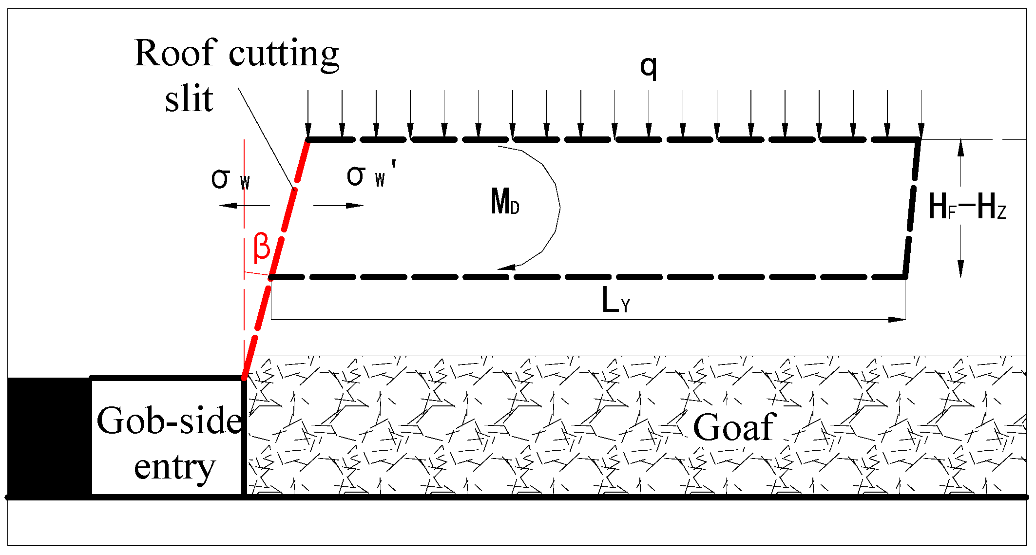
Presently, the roof cutting blasting parameters of each mine are determined via a field blasting test. First, the requirement of the roof cutting connectivity rate is determined through a mechanical analysis and calculation based on the cantilever beam theory, as shown in Figure 5 [23]:
where σW is the tensile stress of the nonconnected part of the presplitting cutting surface, KL is the connectivity rate of roof cutting, σmax is the uniaxial tensile strength of the roof cutting face, MD is the rotary moment on the cutting surface, W is the section modulus of the roof cutting surface, q is the uniformly distributed load generated by the weight of rocks above, LY is the weighting step in the tendency direction, b is the collapse length of the cutting cantilever beam, HF is the roof cutting height, and HZ is the thickness of the immediate roof.
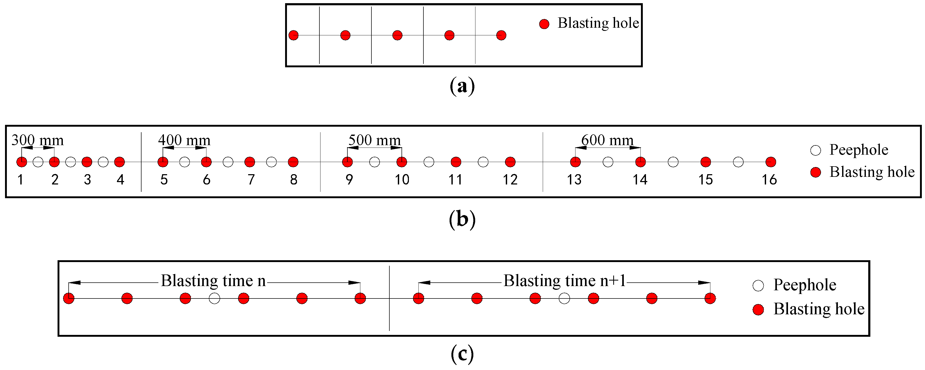
After the connectivity rate of roof cutting is designed based on the above theory, the goaf roof can collapse along the roof cutting surface under the mechanical influence of the cantilever beam, only if the cutting blasting satisfies the design requirements. Therefore, the key parameters of the blasting are determined using a borehole observation rig in the field blasting test to evaluate the connectivity rate of roof cutting. The blasting test usually includes a single hole blasting test, interval hole blasting test, and continuous hole blasting test. The single hole blasting test is used mainly to determine the range of single hole charge weight and the sealing length. The interval hole blasting test is used to determine the reasonable spacing of the blasting holes. The continuous hole blasting test is used to adjust the charge structure and to verify the blasting effect [24]. The arrangement of the holes in a regular test is shown in Figure 6.
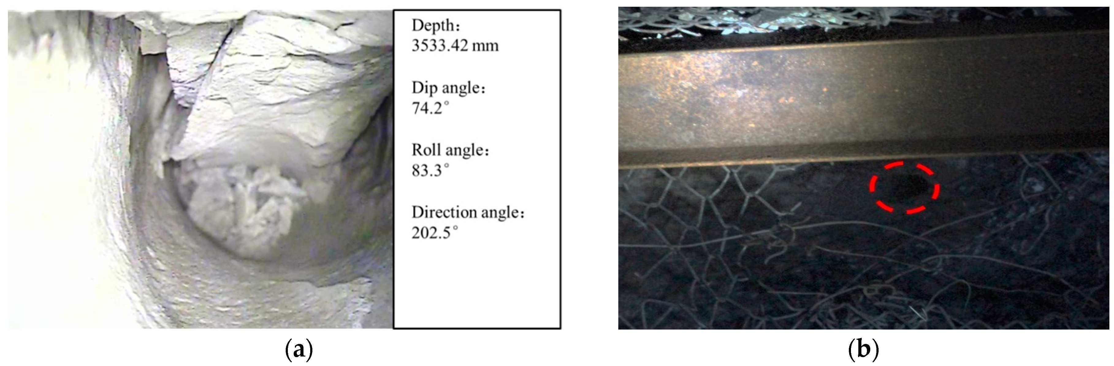
The above-mentioned test can determine the parameters of roof cutting blasting and can provide reference for presplitting blasting under similar roof conditions. However, the test process is tedious and often affects the succession of and cooperation with other related works. In addition, the effectivity of roof cutting in the test is difficult to guarantee. As shown in Figure 7, there is a high probability of occurrence of collapse in the blasting hole, breakage of roof around the hole, or a lower cutting rate. More importantly, as it is guided by the static cantilever beam theory, this test method neglects the stress evolution process of the cutting surface and the goaf roof, that is, it neglects the influence of the premining stress state on the roof cutting effect, and the consequent improvement in the requirements of blasting.
3.2. Typical Mine Examples
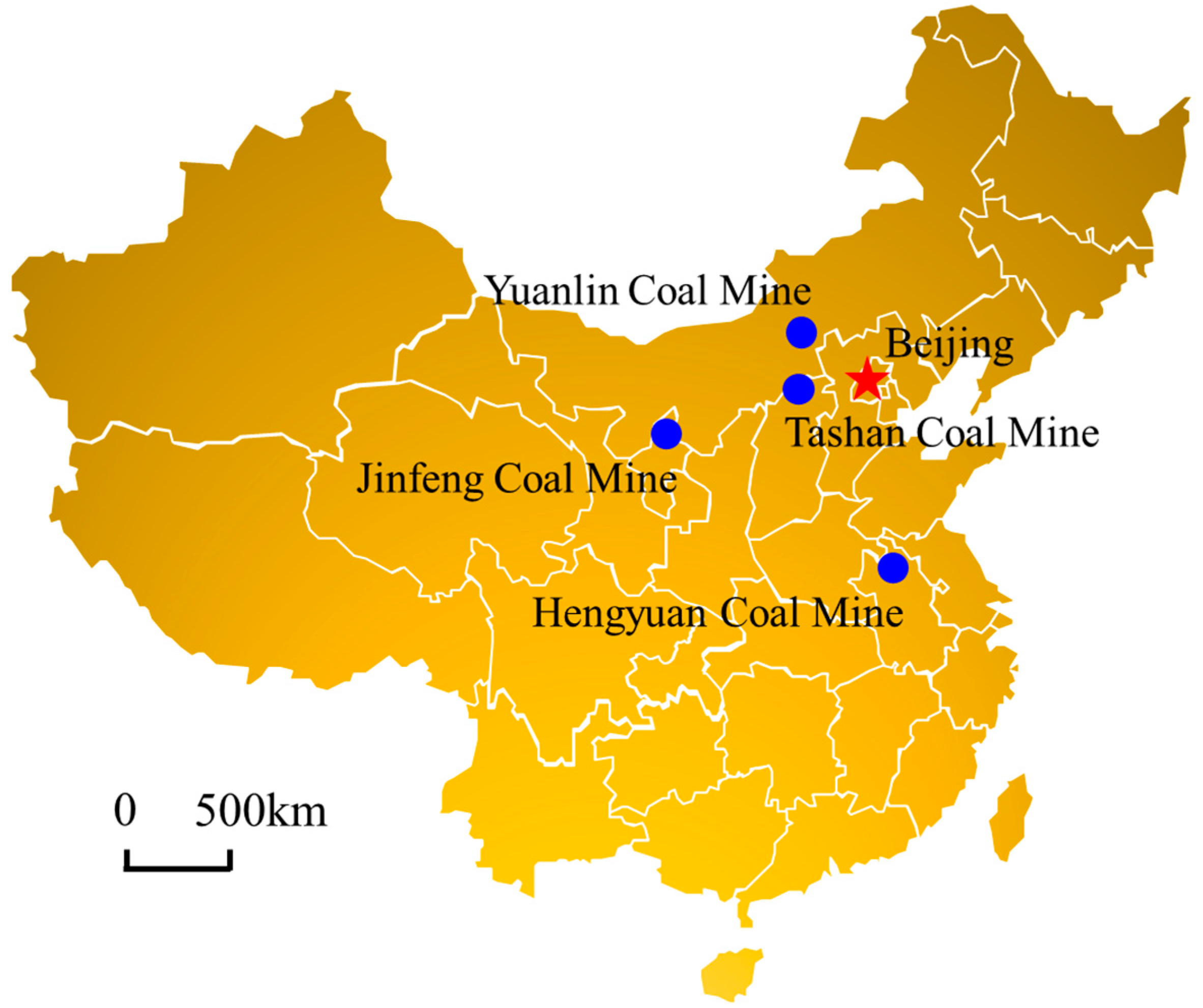
As mentioned in 3.1, the existing determination method for the blasting parameters is inadequate. However, in the early stages of application of the novel entry retaining technology, field blasting tests were inevitable and necessary, not only to realize the preliminary determination of the blasting parameters, but also to obtain the valuable primary field data to make up for the lack of engineering practice. Based on the existing test results, four typical mines are chosen in this study, and their final blasting parameters are presented as follows to provide basic reference for the research performed in this work. The four typical mines are the Tashan Coal Mine, Yuanlin Coal Mine, Jinfeng Coal Mine, and Hengyuan Coal Mine, whose locations are shown in Figure 8.
(1) The 8304 working face of Tashan Coal Mine
The basic parameters of the 8304 working face in the Tashan Coal Mine are listed in Table 1. The roof lithology and roof cutting design in the blasting test area are shown in Figure 9a. The cutting height is 8.3 m, the cutting angle is 15°, and the roof is a composite roof, in which the immediate roof is mudstone and is relatively broken. Therefore, the final charge structure of the explosive is determined as shown in Figure 9b, the length of the sealing section is 2 m, and the charge weight at the lower part of the hole is relatively low. In addition, the field blasting test shows that the average connectivity rate of the roof cutting reaches 82.3% when the spacing of the blasting holes is 500 mm.
Figure 9c is drawn according to the results obtained by the borehole observation rig in the field blasting test, and the roof cutting effect under a 500 mm hole spacing condition is shown in Figure 9d. Among them, the roof cutting connectivity rate per meter Km is calculated as follows:
where lF is the crack length per meter.
(2) The W1-106 working face of Yuanlin Coal Mine
The basic parameters of the W1-106 working face in the Yuanlin Coal Mine are listed in Table 2. The roof lithology and roof cutting design in the blasting test area are shown in Figure 10a. The roof cutting height is 9 m, the cutting angle is 15°, and the roof is hard with no obvious joint development. Therefore, the charge weight of the single hole is relatively large. However, the immediate roof is a mudstone layer in this case, the sealing section length is increased to 2.3 m and the charge weight at the lower part of the hole is decreased to protect the integrity of the surrounding rock. The final charge structure of the explosive is determined as shown in Figure 10b, and the values of the roof cutting connectivity rate with different hole spacings are shown in Figure 10c. The hole spacing adopted in the field is 400 mm, and the average connectivity rate of roof cutting can reach 80.2% under this condition.
(3) The 011810 working face of Jinfeng Coal Mine
The basic parameters of the 011810 working face in the Jinfeng Coal Mine are listed in Table 3. The roof lithology and roof cutting design in the blasting test area are shown in Figure 11a. The cutting height is 9.3 m; the cutting angle is 20°; and the roof is relatively hard, including the immediate roof. Therefore, the sealing section length is determined as 2 m and the charge weight at the lower part of the hole is increased appropriately. The final charge structure of the explosive is determined as shown in Figure 11b, and the statistics of the roof cutting connectivity rate with different hole spacings are shown in Figure 11c. The hole spacing adopted in this field is 500 mm, and the average connectivity rate of roof cutting can reach 77.1% under this condition.
(4) The II632 working face of the Hengyuan Coal Mine
The basic parameters of the II632 working face in the Hengyuan Coal Mine are listed in Table 4. The roof lithology and roof cutting design in the blasting test area are shown in Figure 12a. The cutting height is 7 m, the cutting angle is 15°, and the roof is a soft composite roof with a large total thickness of mudstone in the roof cutting range. Therefore, the charge weight of the blasting hole is relatively small, and the sealing section length is determined as 2.3 m. The final charge structure of the explosive is determined as shown in Figure 12b, and the statistics of the roof cutting connectivity rate with different hole spacings are shown as Figure 12c. The hole spacing adopted in this field is 500 mm, and the average connectivity rate of the roof cutting can reach 81.1% under this condition.
4. Selection and Analysis of Key Indices
4.1. Summary of Roof Cutting Blasting Rules
To summarize the rules of roof cutting blasting and to guide the following research and roof cutting operation, this section combines the design parameters of roof cutting blasting and the related geological data of the above mentioned typical mines. The relevant information is summarized in Table 5.
On the basis of the above table and of Section 3.2, the rules of roof cutting blasting can be summarized as follows:
- (1)
- The mining height can affect the design of the roof cutting and the blasting parameters. Overall, when the mining height is large, the blasting hole will always be designed deeper, and in accordance, the explosive charge will also be larger, and vice versa.
- (2)
- A larger burial depth corresponds to a larger confining pressure of the roadway, and it is easier to deform the blasting hole. Thus, the blasting hole should be blasted in time after drilling. At the same time, a larger confining pressure of the surrounding rock corresponds to a larger explosive charge weight of the blasting hole.
- (3)
- A harder and more complete roof requires a larger explosive charge weight of the blasting hole. When there is a weak interlayer in the roof cutting range, the collapse and plugging of the blasting hole occurs easily after the blasting.
- (4)
- Two aspects need to be considered in the determination of the blasting hole sealing length. The first is that when the explosive charge weight is large, the sealing length must be increased appropriately, and the second is that when the immediate roof is weak, the sealing length must also be increased accordingly to protect the integrity of the immediate roof.
- (5)
- In general, the blasting hole spacing needs to be 500 mm. However, when the roof is hard, such as in the case of a sandstone or conglomerate roof, the hole spacing should be reduced to approximately 400 mm.
- (6)
- The charge structure of the blasting hole usually involves a large charge at the top and a small charge at the bottom. This charge structure can effectively protect the integrity of the roof and make the cutting top crack smoothly, which can make the goaf roof collapse easily. In addition, according to the field test results, the connectivity rate of roof cutting at the hole top is usually larger than that at the hole bottom. When there is a hard interlayer in the roof cutting range, the position of the explosive roll should be adjusted to ensure that the connectivity rate of the roof cutting can meet the requirement.
Among the abovementioned rules, (1)–(3) expound the three factors affecting the explosive charge weight of blasting hole, and (4)–(6) expound the parameter characteristics of the sealing length, hole spacing, and charge structure, respectively. In addition, some geological factors can also affect the roof cutting design and parameter determination of the presplitting blasting, such as the coal seam dip angle and the integrity of roof rock. To summarize, there is a certain regularity in the determination of the roof cutting blasting parameters, but the determination of the specific values is a problem involving multiple factors. Several factors affect the design result concerning the roof cutting blasting, however, some of these are difficult to quantitatively evaluate and the influence weight of each factor is difficult to be accurately calculated using theoretical calculations.
4.2. Analysis of Key Indices
Through research and the subsequent summarization of the mechanics process mechanism and the roof cutting blasting rules of RCPRGER technology, although it is impossible to quantitatively analyze the influencing factors of the key parameters in roof cutting blasting, the logical and causal relations of design can be established, and the key indices affecting the blasting design can be determined.
As shown in Table 5, the reference-related roof cutting blasting can be divided into four categories. The mining height, buried depth, coal seam dip angle, and roof characteristics belong to the geological data; the roof cutting height and roof cutting angle belong to the roof cutting design; the sealing length, explosive charge weight, blasting hole spacing, and charge structure belong to the blasting design; and the average roof cutting connectivity rate belongs to the roof cutting effect. Thus, according to the mechanics process mechanism and the existing roof cutting blasting design method and process, the design logic diagram of roof cutting blasting can be drawn, as shown in Figure 13. Among these parameters, the geological data directly determine the roof cutting design, and the geological data and roof cutting design together affect the blasting design. Finally, the entry retention is determined by the roof cutting design, blasting design, and construction quality. Presently, the key parameters of roof cutting design can be determined using geometric calculations, mechanical analysis, and numerical simulations based on the geological data, while the key parameters in blasting design, the research emphases in this work, are usually determined by field tests. Through the analysis presented in this section, it is noted that the blasting design is a complex fuzzy problem influenced by several factors, and it is difficult to quantitatively measure the influencing factors and the weights of each factor. However, according to the design logic diagram, we can note that the key indices affecting the blasting design are geological conditions, including the mining height; buried depth; coal seam dip angle; roof lithology and roof integrity; and roof cutting design, including roof cutting height, roof cutting angle, and roof cutting connectivity.
5. Neural Network Construction
On the basis of mastering the mechanics process mechanism and the key indices of the design of roof cutting blasting, and to solve the complex fuzzy problem affected by multiple factors, this paper proposes a neural network algorithm design method to substitute the field tests, by utilizing the existing engineering example.
5.1. Introduction of BP Neural Network
Neural network algorithms have a strong advantage in solving fuzzy nonlinear problems and find many applications in the coal mining field, such as in the mining method selection, roof safety evaluation, and mine ventilation system evaluation [25,26]. As the most widely used neural network, the back propagation (BP) algorithm consists of the following two processes: forward computation of data stream (forward propagation) and feedback of error signal (back propagation). Through the alternation of the two processes, the gradient descent strategy of the error function is implemented in the weight vector space, and a set of weight vectors are iteratively searched dynamically in order to minimize the network error. Next, the information extraction and memory process are completed, as shown in Figure 14 [27,28].
In the specific training process, the input and output sample pairs are provided to adjust and correct the weights and thresholds of each neuron in the network by continuously training. For the input of the given training samples, if the output of the network can approximate the output of the given training samples accurately, the network training process is completed. The constantly modifying rule of the weights and thresholds of the network neurons is called the training algorithm in the training process. In this study, the backward propagation algorithm based on the gradient descent method is used. Let there by N given sample pairs (XK, YK) (K = 1, 2, ..., N), for the unit J of layer L. When the sample K is input, the input of J is as follows:
where is the weight, and is the output of unit J when the sample K is input to layer L-1. The transformation function f of the output node uses the sigmoid function as follows:
where e is the natural constant. The error function is as follows:
where is the network output of unit J and is the actual output of unit J.
The overall error is as follows:
The steps of the complete algorithm are as follows:
- (1)
- Selecting the initial value of any weight coefficient.
- (2)
- Performing the given maximum number of training times, or repeating the following procedure until E < ε (ε is the given precision), as follows:
- (a)
- Calculating , , and of each unit (K = 2, …, N).
- (b)
- Correcting the weight of each unit as follows:where μ is the training rate.
5.2. Construction of Neural Network
According to the analysis given in Section 3, the sample space of the BP neural network corresponding to the blasting parameter design is first constructed as shown in Table 6. The mining height has no direct influence on the blasting parameter design and it is the only key factor affecting the roof cutting height design. Thus, only the roof cutting height is selected as an independent variable between the two. The buried depth and coal seam dip angle are taken as the average values of the whole working face, and for the coal seam dip angle, the counterclockwise direction is assumed as the positive value. The roof hardness is calculated according to the weighted average of the Mohs hardness according to the thickness of each rock layer. The roof integrity can be divided into five categories, namely, complete, less complete, little broken, broken, and extremely broken, according to the geological reports of each mine, and the five categories are awarded 5 to 1 points, respectively, so that the parameter can be calculated as an index in the neural network. Furthermore, according to the mechanics process mechanism of the RCPRGER technology, it is known that the roof cutting connectivity is also affected by the subsequent mining process. Therefore, only the sealing length, hole spacing, and single hole charge weight are selected as the dependent variables in the neural network.
Subsequently, MATLAB programming is used to train and solve the network. Because each index has a different dimension and magnitude, in order to eliminate the dimensional difference, the first step is to standardize the original data, that is, the average value of each variable is made 0 and the variance is made 1, as follows:
where and are the average and standard deviation of the variable j, respectively; I = 1, 2, …, n and j= 1, 2, …, p, where n and p indicate the numbers of samples and variables, respectively.
The third step is to determine the number of neural network layers and neurons. A three-layer BP neural network with one hidden layer can realize any mapping of m dimensions to n dimensions. Increasing the number of network layers can reduce the calculation error to a certain extent, but it also increases the training and solving time. Thus, the layers are designed to be three in this study [29,30]. Next, according to the neural network sample space and the solution requirements, the number of neurons in the output, input, and hidden layers is set to be three, six, and nine, respectively, according to the following empirical formula:
where nmid, nin, and nout denote the number of neurons in the hidden, input, and output layers, respectively; a is a constant number between 1 to 10, and is set as 6 in this study.
In this study, the sample space matrix of the input layer is as follows:
The sample space matrix of the output layer is as follows:
The last step involves the training and verification of the neural network. The training process has been described in Section 5.1. In this study, the training rate is 0.05, the maximum training frequency is 50,000, and the target training error is less than 0.001. After the network training is completed, the four typical mines are reused to verify the training effect. The resulting matrix is as follows:
Based on the matrix, the verification results are shown in Figure 15. The numbers 1, 2, 3, and 4 on the abscissa represent the four typical mines (i.e., the Tashan Coal Mine, Yuanlin Coal Mine, Jinfeng Coal Mine, and Hengyuan Coal Mine, respectively).
Through the neural network simulation, the three key parameters—sealing length, hole spacing, and single hole charge weight—can be determined. Reusing the four typical mines for verification, the maximum error of the three key parameters in the neural network calculation is 0.48%, which can satisfy the field requirement. The charge structure, another key parameter in the blasting design, can be determined by field tests by obtaining the abovementioned three parameters, and by considering the structure of the roof stratum and common charge rules. Compared with the original field test process, the proposed field test is considerably simplified. Moreover, the charge structure can also be determined according to the neural network built according to the key parameters considering all of the energy gathering pipes. The principle is the same as that of the abovementioned calculation process, and thus, a detailed explanation is not presented in this paper. In this study, only four typical mine samples are selected for neural network training, and after the training is completed, the verification also uses the same four mines. Thus, the sample size is relatively small, and in further research, the sample size of mine blasting parameters should be continuously increased in order to further improve the neural network construction of the cutting blasting parameters. The interdisciplinary research reported in this paper is an attempt using an intelligent algorithm to simplify the design process of roof cutting blasting in RCPRGER, which can eliminate the complex design process in the field test and the uncertain influence of the blasting test on entry retention, and the efficiency and quality of key parameter design in roof cutting blasting can be considerably improved.
6. Conclusions
- (1)
- RCPRGER is a research hotspot for mining in China. First, this study analyzes the mechanics process mechanism of roof cutting pressure releasing technology, and categorizes the stress evolution of the surrounding rocks in the entry retaining process into the following six stages: original rock stress state, entry excavation stress state, bolt-cable support stress state, roof cutting stress state, premining stress state, and postmining stress state. Based on this, the mechanical relationship between the roof cutting and entry retention is explained using Mohr’s stress circle.
- (2)
- Through the summarization of the existing design methods of roof cutting blasting, and the determination of the key parameters of roof cutting blasting in four typical mines, including in the Tashan Coal Mine, Yuanlin Coal Mine, Jinfeng Coal Mine, and Hengyuan Coal Mine, the geological characteristics, distribution of the roof cutting connectivity rate, and the charge structure of the explosive are obtained, which can provide references for the application of the RCPRGER technology in other mines, as well as the basic samples for the neural network construction in this study.
- (3)
- The neural network algorithm has been considerably developed in recent years, but its application in RCPRGER technology is still a blank. On the basis of the considered four typical mines, six rules are established concerning the four key parameters—charge weight of blasting hole, blasting hole sealing length, blasting hole spacing, and charging structure of the explosive. Next, the logic diagram of the roof cutting blasting design is established, the key indices affecting the blasting design are determined, and the design process is defined as a complex fuzzy problem affected by multiple factors. Furthermore, a specific concept of using the neural network intelligent algorithm to optimize the design of the roof cutting blasting parameters has been proposed.
- (4)
- Aiming at the design of the key parameters of roof cutting blasting, a three-layer BP neural network with six input units, nine hidden units, and three output units is constructed by taking four typical mines as the sample space. Through the training of the neural network, the three key parameters—blasting hole sealing length, hole spacing, and single hole charge weight—can be quickly determined, with an error of less than 0.48%. This method considerably simplifies the design process of the blasting parameters. Moreover, the charge structure parameters can also be determined according to this method. However, presently, there is a shortcoming of limited sample space in the construction of this neutral network. Therefore, the sample space should be supplemented in further research and practice in order to improve the accuracy, efficiency, and applicability of this design method, which can further promote the application and development of the RCPRGER technology. The interdisciplinary research described in this paper represents an exploration using the intelligent algorithm to simplify the design process of roof cutting blasting in RCPRGER.
Author Contributions
All of the authors contributed to this paper. M.H. conceived and designed the research. X.M. and H.W. performed the theoretical analysis and field tests. J.S. provided theoretical guidance in the research process. X.L. and E.Z. analyzed the data.
Funding
This research was funded by the National Nature Science Foundation of China grant number No. 51574248, and the State Key Program of National Nature Science Foundation of China grant number No. 51134005.
Conflicts of Interest
The authors declare no conflict of interest.
References
- Cristobal, J.; Guillen, G.G.; Jimenez, L. Optimization of global and local pollution control in electricity production from coal burning. Appl. Energy 2012, 92, 369–378. [Google Scholar] [CrossRef]
- Ameri, M.; Mokhtari, H.; Sani, M.M. 4E analyses and multi-objective optimization of different fuels application for a large combined cycle power plant. Energy 2018, 156, 371–386. [Google Scholar] [CrossRef]
- Milici, R.C.; Flores, R.M.; Stricker, G.G. Coal resources, reserves and peak coal production in the United States. Int. J. Coal Geol. 2013, 113, 109–115. [Google Scholar] [CrossRef]
- Yang, X.J.; Wang, E.Y.; Wang, Y.J.; Gao, Y.B.; Wang, P. A study of the large deformation mechanism and control techniques for deep soft rock roadways. Sustainability 2018, 10, 1100. [Google Scholar] [CrossRef]
- Ma, X.G.; He, M.C.; Wang, J.; Gao, Y.B.; Zhu, D.Y.; Liu, Y.X. Mine strata pressure characteristics and mechanisms in gob-side entry retention by roof cutting under medium-thick coal seam and compound roof conditions. Energies 2018, 11, 2539. [Google Scholar] [CrossRef]
- Zhang, N.; Han, C.L.; Kan, J.G.; Han, J.-G.; Zheng, X.-G. Theory and practice of surrounding rock control for pillarless gob-side entry retaining. J. China Coal Soc. 2014, 39, 1635–1641. [Google Scholar]
- Kang, H.P.; Niu, D.L.; Zhang, Z.; Lin, J.; Fan, M. Deformation characteristics of supporting rock and supporting technology of gob-side entry retaining. Chin. J. Rock Mech. Eng. 2010, 29, 1977–1987. [Google Scholar]
- He, M.C. Progress and challenges of soft rock engineering in depth. J. China Coal Soc. 2014, 39, 1409–1417. [Google Scholar]
- He, M.C.; Ma, X.G.; Niu, F.L.; Wang, J.; Liu, Y.X. Adaptability research and application of rapid gob-side entry retaining formed by roof cutting and pressure releasing with composite roof and medium thick coal seam. Chin. J. Rock Mech. Eng. 2018, 37, 1–15. [Google Scholar]
- Chi, B.S.; Zhou, K.F.; He, M.C.; Yang, J.; Wang, Q.; Ma, X.G. Optimization research on supporting parameters of roof cutting entry retaining with large mining height face. Coal Sci. Technol. 2017, 45, 128–133. [Google Scholar]
- Ma, X.G.; Wang, J.; Wu, H.L.; Liu, Y.X.; Jiang, Q.Q. Experimental study on blasting of roof cutting with no pillar mining in working face of Tashan Coal Mine. Coal Sci. Technol. 2018, 46, 27–32. [Google Scholar]
- Guo, P.F.; Zhang, G.F.; Tao, Z.G. Blasting technology of gateway retaining along goaf pressure release by roof cutting in hard and weak complex roof. Coal Sci. Technol. 2016, 44, 120–124. [Google Scholar]
- Sun, X.M.; Liu, X.; Liang, G.F. Key parameters of gob-side entry retaining formed by roof cut and pressure releasing in thin coal seams. Chin. J. Rock Mech. Eng. 2014, 33, 1449–1456. [Google Scholar]
- Zhang, X.H.; Guo, P.F.; Wang, J.; Wang, H. Study on pressure relief drilling spacing optimization in gob-side entry retaining. Coal Technol. 2016, 35, 6–8. [Google Scholar]
- Ma, X.G.; He, M.C.; Sun, J.D.; HU, J.; Zhang, X.Y.; Zhang, J.B. Research on the design of roof cutting parameters of noncoal pillar gob-side entry retaining mining with roof cutting and pressure releasing. Geotech. Geol. Eng. 2018, 8, 1–16. [Google Scholar] [CrossRef]
- Jiang, J.Q.; Wang, G.J.; Zhang, D.M.; Dai, J. Basic movement law of overlying strata. In Mining Pressure and Strata Control; China University of Mining & Technology: Bejing, China, 2007; pp. 13–16. [Google Scholar]
- Jaeger, J.; Cook, N. Fundamentals of Rock Mechanics; Chapman and Hall LTD: London, UK, 1969; pp. 53–108.
- Jiang, J.Q.; Wang, G.J.; Zhang, D.M.; Dai, J. Control principle and technology of roadway surrounding rock. In Mining Pressure and Strata Control; China University of Mining & Technology: Bejing, China, 2007; pp. 232–234. [Google Scholar]
- He, M.C.; Gao, Y.B.; Yang, J.; Wang, J.; Wang, Y.; Zhu, Z. Engineering experimentation of gob-side entry retaining formed by roof cutting and pressure release in a thick-seam fast-extracted mining face. Rock Soil Mech. 2018, 1, 254–264. [Google Scholar]
- Liu, Y.L.; Li, W.B.; Huang, X.Y. The Application of roof cutting and pressure relief blasting technology in gob-side entry retaining. Saf. Coal Mines 2016, 40, 132–135. [Google Scholar]
- He, M.C.; Gao, Y.B.; Yang, J.; Guo, Z.; Wang, E.; Wang, Y. An energy-gathered roof cutting technique in no-pillar mining and its impact on stress variation in surrounding rocks. Chin. J. Rock Mech. Eng. 2017, 6, 1314–1325. [Google Scholar]
- Chen, Y.; Hao, S.P.; Chen, Y.T. Study on the application of short-hole blasting with guide hole to roof cutting pressure relief of gob-side entry retaining. J. Min. Saf. Eng. 2015, 32, 253–259. [Google Scholar]
- Shi, J.J.; Ma, N.J.; Bai, Z.S. Analysis on roof broken location of gateway retained along goaf and technology of roof support. Coal Sci. Technol. 2013, 41, 35–38. [Google Scholar]
- Li, M. Study on application of blasting cut top and combined support technology in gob-side entry retaining. China Energy Environ. Prot. 2017, 39, 137–144. [Google Scholar]
- Wu, A.X.; Guo, L.; Yu, J.; Yang, Y.P.; Xiao, X. Neural network model construction and its application in fuzzily optimization of mining method. Min. Metall. Eng. 2003, 23, 6–11. [Google Scholar]
- Wu, Y.L. Study on prediction forecast of rock burst based on MATLAB neural networks. Shandong Univ. Sci. Technol. 2005, 6, 25–30. [Google Scholar]
- Chen, J.H.; Liu, L.; Zhou, Z.Y.; Yong, X.Y. Optimization of mining methods based on combination of principal component analysis and neural networks. J. Cent. South Univ. 2010, 41, 1967–1972. [Google Scholar]
- Li, Y.; Liu, J. Application of combination of neural networks and principal component analysis in mining engineering. J. Cent. South Univ. For. Technol. 2010, 30, 140–146. [Google Scholar]
- Ma, X.G.; Sun, J.D. Analysis on dragline rotation time—Consuming and efficiency division. Coal Sci. Technol. 2015, 43, 51–54. [Google Scholar]
- Xiao, S.S.; Li, K.M.; Li, T.; Ma, L.; Chang, Z. Prediction of dragline’s production capacity based on BP neural network. Met. Mine 2012, 43, 41–43. [Google Scholar]
Figure 1.
Sketch map of the roof cutting pressure releasing gob-side entry retaining (RCPRGER) technology: (a) before working face mining; (b) after working face mining.
Figure 1.
Sketch map of the roof cutting pressure releasing gob-side entry retaining (RCPRGER) technology: (a) before working face mining; (b) after working face mining.

Figure 2.
Stress state evolution process of surrounding rock: (a) original rock stress state; (b) entry excavation stress state; (c) bolt-cable support stress state; (d) roof cutting stress state; (e) premining stress state; (f) postmining stress state.
Figure 2.
Stress state evolution process of surrounding rock: (a) original rock stress state; (b) entry excavation stress state; (c) bolt-cable support stress state; (d) roof cutting stress state; (e) premining stress state; (f) postmining stress state.

Figure 3.
Device and principle of bidirectional concentrated tension blasting (BCTB): (a) structure of connecting sleeve and energy gathering pipe; (b) blasting control mechanism.
Figure 3.
Device and principle of bidirectional concentrated tension blasting (BCTB): (a) structure of connecting sleeve and energy gathering pipe; (b) blasting control mechanism.

Figure 4.
Mechanics model of BCTB technology.

Figure 5.
Schematic of the mechanical model corresponding to the cutting cantilever beam.

Figure 6.
Blasthole layout of blasting test: (a) single hole blasting test; (b) interval hole blasting test; (c) continuous hole blasting test.
Figure 6.
Blasthole layout of blasting test: (a) single hole blasting test; (b) interval hole blasting test; (c) continuous hole blasting test.

Figure 7.
Images of hole plugging and roof crushing: (a) hole plugging; (b) roof crushing.

Figure 8.
Locations of four typical mines.

Figure 9.
Roof cutting blasting design of the 8304 working face: (a) roof cutting design; (b) schematic of charge structure; (c) statistical drawing of roof cutting connectivity rate; (d) fissure diagram of the peep hole with 500 mm spacing.
Figure 9.
Roof cutting blasting design of the 8304 working face: (a) roof cutting design; (b) schematic of charge structure; (c) statistical drawing of roof cutting connectivity rate; (d) fissure diagram of the peep hole with 500 mm spacing.

Figure 10.
Roof cutting blasting design of the W1-106 working face: (a) roof cutting design; (b) schematic of charge structure; (c) statistical drawing of roof cutting connectivity rate.
Figure 10.
Roof cutting blasting design of the W1-106 working face: (a) roof cutting design; (b) schematic of charge structure; (c) statistical drawing of roof cutting connectivity rate.


Figure 11.
Roof cutting blasting design of the 011810 working face: (a) roof cutting design; (b) schematic of charge structure; (c) statistical drawing of roof cutting connectivity rate.
Figure 11.
Roof cutting blasting design of the 011810 working face: (a) roof cutting design; (b) schematic of charge structure; (c) statistical drawing of roof cutting connectivity rate.


Figure 12.
Roof cutting blasting design of the II632 working face: (a) roof cutting design; (b) schematic of charge structure; (c) statistical drawing of roof cutting connectivity rate.
Figure 12.
Roof cutting blasting design of the II632 working face: (a) roof cutting design; (b) schematic of charge structure; (c) statistical drawing of roof cutting connectivity rate.


Figure 13.
Relationship diagram of roof cutting and blasting design.

Figure 14.
Topological structure of a three-layer back propagation (BP) neural network where Xp1, Xp2… Xpm are the inputs of the neural network; Yp1, Yp2… Ypm are the outputs of the neural network; i, j, and k are the three layers; and Wij and Wjk are the weights between the adjacent layers.
Figure 14.
Topological structure of a three-layer back propagation (BP) neural network where Xp1, Xp2… Xpm are the inputs of the neural network; Yp1, Yp2… Ypm are the outputs of the neural network; i, j, and k are the three layers; and Wij and Wjk are the weights between the adjacent layers.

Figure 15.
Training result of neural networks.


Table 1.
Basic parameters of the 8304 working face in the Tashan Coal Mine.
| Coal Seam Thickness/Average Thickness (m) | 1.80–3.55/3.1 | Depth (m) | 367–411 |
| Mining Height (m) | 3.1 | Dip Angle/Average Dip Angle (°) | 2–6/4 |
| Strike Length (m) | 670 | Length of the Working Face (m) | 127 |
| Immediate Roof/Thickness (m) | Mudstone/1.4 | Immediate Floor/Thickness (m) | Mudstone/3.2 |
| Basic Roof/Thickness (m) | Fine sandstone/5.5 | Basic Floor/Thickness (m) | Siltstone/3.1 |
Table 2.
Basic parameters of the W1-106 working face in the Yuanlin Coal Mine.
| Coal Seam Thickness/Average Thickness (m) | 2.50–4.50/3.2 | Depth (m) | 124–155 |
| Mining Height (m) | 3.2 | Dip Angle/Average Dip Angle (°) | 5–15/8 |
| Strike Length (m) | 1399 | Length of the Working Face (m) | 174 |
| Immediate Roof/Thickness (m) | Mudstone/1.4 | Immediate Floor/Thickness (m) | Fine sandstone/3.9 |
| Basic Roof/Thickness (m) | Conglomerate/5.3 | Basic Floor/Thickness (m) | Coarse sandstone/6.5 |
Table 3.
Basic parameters of the 011810 working face in the Jinfeng Coal Mine.
| Coal Seam Thickness/Average Thickness (m) | 3.30–4.20/3.8 | Depth (m) | 214–329 |
| Mining Height (m) | 3.8 | Dip Angle/Average Dip Angle (°) | 7–19/13 |
| Strike Length (m) | 1023 | Length of the Working Face (m) | 260 |
| Immediate Roof/Thickness (m) | Fine sandstone/1.5 | Immediate Floor/Thickness (m) | Siltstone/4.5 |
| Basic Roof/Thickness (m) | Siltstone/7.2 | Basic Floor/Thickness (m) | Fine sandstone/6.7 |
Table 4.
Basic parameters of the II632 working face in the Hengyuan Coal Mine.
| Coal Seam Thickness/Average Thickness (m) | 2.17–3.30/2.8 | Depth (m) | 600–777 |
| Mining Height (m) | 2.8 | Dip Angle/Average Dip Angle (°) | 1–26/9 |
| Strike Length (m) | 1725 | Length of the Working Face (m) | 183 |
| Immediate Roof/Thickness (m) | Mudstone/2.3 | Immediate Floor/Thickness (m) | Mudstone/2.6 |
| Basic Roof/Thickness (m) | Fine sandstone/6.0 | Basic Floor/Thickness (m) | Fine sandstone/5.7 |
Table 5.
Summary of the typical mine blasting data.
| Coal Mine | Basic Geological Data | Roof Cutting and Blasting Design | |||||||||
|---|---|---|---|---|---|---|---|---|---|---|---|
| Mining Height (m) | Buried Depth (m) | Dip Angle (°) | Roof Type | Roof Cutting Height (m) | Roof Cutting Angle (°) | Sealing Length (m) | Explosive Rolls | Hole Spacing (mm) | Charge Structure | Connectivity Rate (%) | |
| Tashan | 3.1 | 367–411 | 2~6/4 | Composite | 8.3 | 15 | 2.0 | 15 | 500 | 44331 | 82.3 |
| Yuanlin | 3.2 | 124–155 | 5~15/8 | Hard | 9.0 | 15 | 2.3 | 18 | 400 | 55431 | 80.2 |
| Jinfeng | 3.8 | 214–329 | 7~19/13 | Hard immediate roof | 9.3 | 20 | 2.0 | 14 | 500 | 43322 | 77.1 |
| Hengyuan | 2.8 | 600–777 | 1~26/9 | Soft composite | 7.0 | 15 | 2.3 | 10 | 500 | 4321 | 81.1 |
Table 6.
Sample set of blasting parameters for back propagation (BP) neural network.
| Coal Mine | Buried Depth (m) | Dip Angle (°) | Roof Hardness | Roof Integrity | Roof Cutting Height (m) | Roof Cutting Angle (°) | Sealing Length (m) | Hole Spacing (mm) | Explosive Rolls |
|---|---|---|---|---|---|---|---|---|---|
| Tashan | 389 | 4 | 4.8 | 4 | 8.3 | 15 | 2.0 | 500 | 15 |
| Yuanlin | 140 | 8 | 7.1 | 5 | 9.0 | 15 | 2.3 | 400 | 18 |
| Jinfeng | 272 | 13 | 5.1 | 5 | 9.3 | 20 | 2.0 | 500 | 14 |
| Hengyuan | 689 | 9 | 3.7 | 4 | 7.0 | 15 | 2.3 | 500 | 10 |
© 2018 by the authors. Licensee MDPI, Basel, Switzerland. This article is an open access article distributed under the terms and conditions of the Creative Commons Attribution (CC BY) license (http://creativecommons.org/licenses/by/4.0/).
Share and Cite
MDPI and ACS Style
Ma, X.; He, M.; Sun, J.; Wang, H.; Liu, X.; Zhen, E. Neural Network of Roof Cutting Blasting Parameters Based on Mines with Different Roof Conditions. Energies 2018, 11, 3468. https://doi.org/10.3390/en11123468
AMA Style
Ma X, He M, Sun J, Wang H, Liu X, Zhen E. Neural Network of Roof Cutting Blasting Parameters Based on Mines with Different Roof Conditions. Energies. 2018; 11(12):3468. https://doi.org/10.3390/en11123468
Chicago/Turabian StyleMa, Xingen, Manchao He, Jiandong Sun, Haohao Wang, Xiaoyu Liu, and Enze Zhen. 2018. "Neural Network of Roof Cutting Blasting Parameters Based on Mines with Different Roof Conditions" Energies 11, no. 12: 3468. https://doi.org/10.3390/en11123468
Note that from the first issue of 2016, this journal uses article numbers instead of page numbers. See further details here.