Closed Adsorption Heat Storage—A Life Cycle Assessment on Material and Component Levels
by
 ,
,
Björn Nienborg
1,*, 
Tobias Helling
1,
Dominik Fröhlich
1,
Rafael Horn
2,
Gunther Munz
1 and
Peter Schossig
1 1
Fraunhofer ISE Institute for Solar Energy Systems, Heidenhofstr. 2, 79110 Freiburg, Germany
2
Institute for Acoustics and Building Physics, University of Stuttgart, 70569 Stuttgart, Germany
*
Author to whom correspondence should be addressed.
Energies 2018, 11(12), 3421; https://doi.org/10.3390/en11123421
Submission received: 14 November 2018
/
Revised: 28 November 2018
/
Accepted: 3 December 2018
/
Published: 6 December 2018
(This article belongs to the Section D: Energy Storage and Application)
Abstract
:Closed adsorption storages have been investigated in several projects for heat storage in building applications with focus on energy density and performance. This study complements this research with the assessment of the environmental impacts over the life cycle. Global warming potential (GWP) was chosen as the assessment criterion. Selected sorption materials in combination with water as the refrigerant were analyzed first by themselves and then embedded in a generic storage configuration. Sensible storage in water served as the reference benchmark. Results on material and component level showed that the relative storage capacity compared to water under realistic operating conditions reached values of below 4 and 2.5, respectively, in the best cases. Since the effort for producing the sorbents as well as the auxiliary material demand for assembling storage components was significantly higher than in the reference case, the specific environmental impact per storage capacity also turned out to be ~2.5 to ~100 times higher. We therefore suggest focusing sorption storage research on applications that (a) maximize the utilization of the uptake of sorbents, (b) do not compete with water storages, and (c) require minimal auxiliary parts.
1. Introduction
The promotion and use of renewable energy sources is a key strategy for combating climate change.
In order to match their fluctuating supply to the demand, energy storages play an essential role [1]. In the field of heat storage, currently sensible hot water storages are widely used, especially for short-term energy storage. In regard to their extended use in combination with renewables, storage losses and space consumption are disadvantageous. Therefore, thermo-chemical materials (TCM) have been widely studied in the past couple of years, as they potentially allow higher storage densities and almost loss-free storage of thermal energy. The latter is the reason why they have been considered very promising for seasonal storage in combination with solar thermal energy [2].
A common type of TCM studied is based on adsorption where a gas or vapor (sorbate) adheres to a microporous sorbent material. During charging, which is an endothermic reaction, the sorbent is heated and releases the adsorbed vapor. During discharging, the working pair is brought back together, which releases heat in the exothermic adsorption process [3]. So-called open systems are connected to the atmosphere, and here, the sorbate is released and extracted from air which also serves as heat transfer medium. In contrast, closed systems consist of a hermetic sorption reactor with connected evaporator or condenser for the sorbate and operate under a sorbate-specific pressure (e.g., a vacuum, in the case of water or methanol, or overpressure for ammonia). Heat is supplied and extracted via heat exchangers. Due to its favorable properties, many potential working pairs using water as the sorbate have been investigated, e.g., silica gel [4], zeolites [5,6], aluminum phosphates (AlPOs) [7], metal organic frameworks (MOFs) [8], activated carbon, and a variety of composites [4,7].
Jähnchen et al. reported theoretical energy storage densities for TCMs in closed storages of 93 kWh/m3 (silica gel/water) and 160 kWh/m3 for zeolite NaX/water systems [7]. Aydin et al. quantified the storage densities of silica gel/water to be 182 kWh/m3 and 162 kWh/m3 for the zeolite/water working pair [2]. By using salt-impregnated matrixes, high values also seem achievable: For materials with vermiculite as the substrate, values of up to 253 kWh/m3 and even 330 kWh/m3 have been reported, although the latter analysis showed stability problems [9,10].
Even though these results indicate a great potential of solid sorption for thermal energy storage, their performance is significantly lower considering actual operating conditions. Frazzica et al. performed calculations assuming a solar thermal heat supply and low temperature radiators for heat distribution (Tdesorpion = 120 °C, Tadsorpion = 50 °C, Tevaporator = 10 °C; Tcondenser = 30 °C, closed system) and reported storage densities of 53 kWh/m3 with a water/zeolite 13X working pair and 38 kWh/m3 for water/silica gel [6]. Permyakova et al. determined a storage density of 51 kWh/m3 for zeolite 13X based on thermogravimetric measurements of the material in combination with water [11].
Several pilot projects have studied the performance of solid-sorption-based storage components in heating systems. In frame of the EU Project “Modestore”, the technical feasibility of a closed thermochemical storage with water/silica gel storage was demonstrated. The realized unit reached a storage density of 33 kWh/m3 at 85 °C charging and 25 °C discharging temperature. A laboratory scale storage with Z13X/water yielded a specific capacity of 58 Wh/m3 with 180 °C and 20 °C charging and discharging temperatures, respectively [12]. The University of Stuttgart demonstrated in their SolSpaces project that their open TCS prototype (with zeolite) was able to meet the heating requirements of a small house with 43 m² [13].
As can be seen, a lot of research has been done on the performance of TCMs on different scales, partly complemented with (usually rather disillusioning) cost estimations (e.g., References [14,15]). In order to increase operating time and therefore economic viability, Vasta et al. therefore recommend looking at multi-functional applications such as cooling and heat pumping [16].
Few publications include life cycle assessment (LCA) results on TCMs. Munz et al. performed a generic potential analysis for open sorption using the cumulated energy demand for production as the evaluation criterion. They found that the material impact must be below 4.5 kWh/kg but ranges from 5 to 7 kWh/kg [15]. Horn et al. evaluated the energetic amortization of pure sorption materials, ignoring any required auxiliary parts or energy, for an assumed solar thermal application (100 °C desorption, 35 °C adsorption, and 10 °C condensation/evaporation temperature, respectively). Under these boundary conditions, silica gel and Z13X requires ~60 and ~260 cycles, respectively, to supply the energy consumed during their production [17]. Bertsch compared the LCA of solar thermal systems with water and open sorption storages. He concluded that the latter has a higher thermal performance which is offset by a higher auxiliary energy demand [18].
Further studies on the LCA of (closed) sorption based thermal storages are not known. Evidently, a holistic and comparative ecological evaluation including not only material but also component level is still pending and therefore addressed in this work to address this issue for closed solid-sorption-based thermochemical storage. This paper focuses on the storage and provision of heat in temperature ranges suitable for building applications.
2. Materials and Methods
As sorption materials cannot be used in storage applications by themselves, this paper contemplates the environmental impact not only at the material level but also in a generic sorption storage component, which comprises all the required parts (such as heat exchangers, containment, and insulation). At this scale, an initial quantitative comparison with water storages as the reference is possible. The final step, the comparative evaluation of the performance of the respective storage components in a heating system, lies outside the scope of this journal and will be provided in a future publication.
2.1. Life Cycle Assessment and Applied Impact Categories
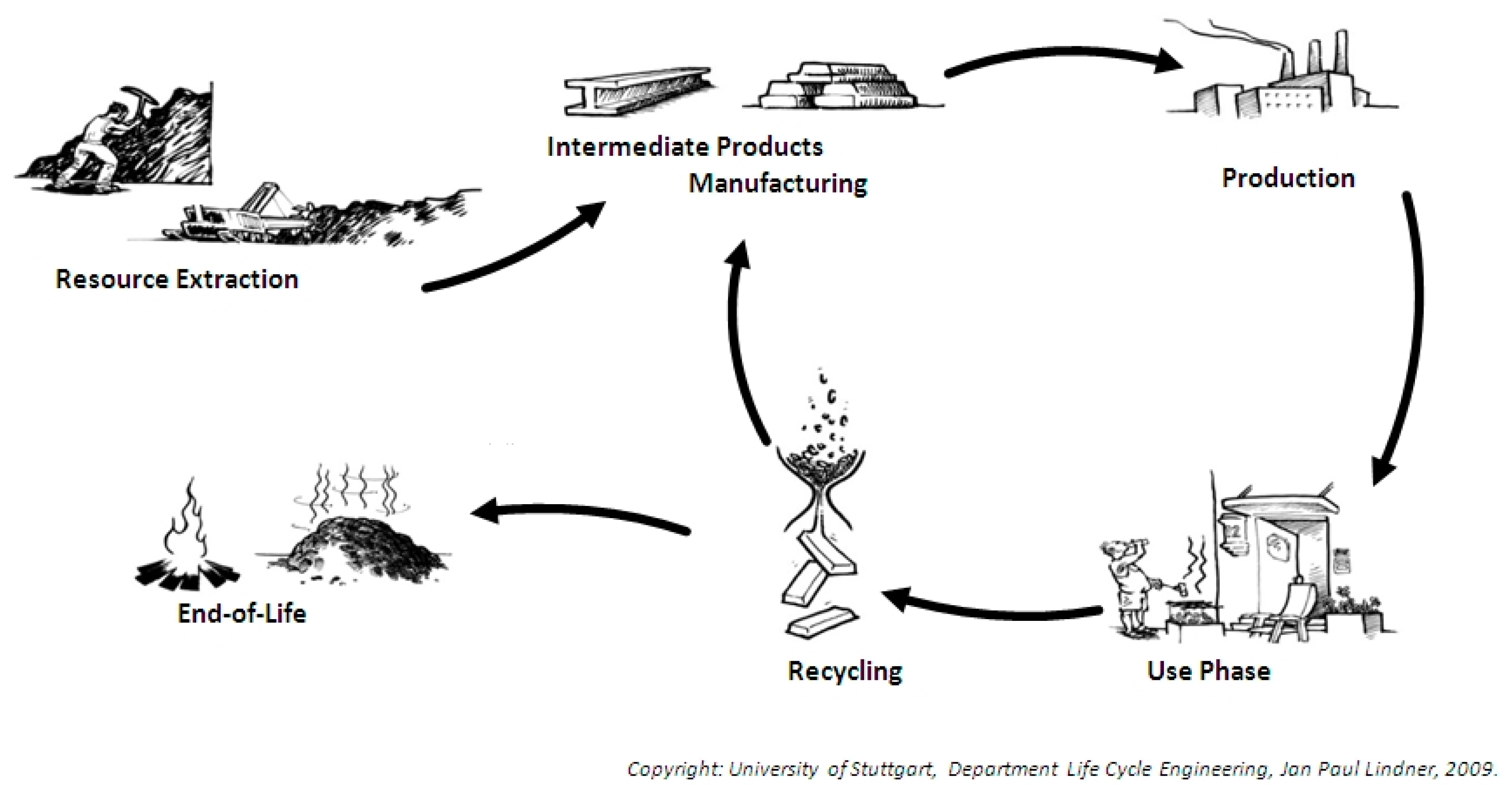
The method of life cycle assessment (LCA) refers to a systematic analysis of the environmental impacts of a product from cradle to grave. As shown in Figure 1, it includes all stages from resource extraction through processing, manufacturing, transport, use, and including maintenance and end-of-life (reuse, recycling, or disposal). It is regulated by ISO standards [19,20] and further substantiated for the construction sector by European Norms [21,22]. A large number of impact categories are available for the assessment, which ranges from land use, water stress, and ecological and human toxicity, to climate and energy related values such as global warming potential (GWP) or primary energy (PE) consumptions (comprising both energetic and material use).
In the present study, we concentrated on the latter two as they are recommended in the relevant standards, are well known, and rest upon well-validated models [23]. The assessment was carried out with the software suite GaBi and relied on the corresponding material and process databases (http://www.gabi-software.com).
2.2. Description of Considered Materials
This study concentrated on five sorption materials, which are considered promising for building heating applications due to their thermodynamic properties. One representative of the well-known material types, silica gel, silicoaluminumphosphates (SAPO), and zeolites, was each included. Two newer materials out of the group of metal organic frameworks (MOFs) complemented the selection. Finally one promising (because it is apparently stable) salt-composite material with “sorption-like” behavior was considered.
2.2.1. Considered Production Processes
Essential for a substantiated evaluation of the materials is the realistic implementation of the corresponding production processes. For the established materials, abundant information is available on the synthesis routes (examples in Table 1) which have been scaled to industrial batch production levels. For the MOFs and the composite, information is scarcer and only refers to laboratory scales, which, of course, is not comparable to industry scales in terms of the specific environmental impact of the product. For this reason, their production has also been upscaled to industry scale batch processes using the same process models (with boundary conditions adapted to their synthesis routes) as those for the remaining materials. All materials are assumed to be provided as pellets; therefore, all but silica gel and the composite contain ten mass-percent of a silicon-resin-based binder, which was chosen for its longevity and resistance.
2.2.2. Determination of the Thermal Storage Capacity
In order to determine the sorption-equilibria of the first five materials listed in Table 1, volumetric water sorption isotherms were measured at 25, 40, and 60 °C on a Quantachrome Vstar. Prior to the measurement, all samples were degassed under reduced pressure at 250 °C for 24 h.
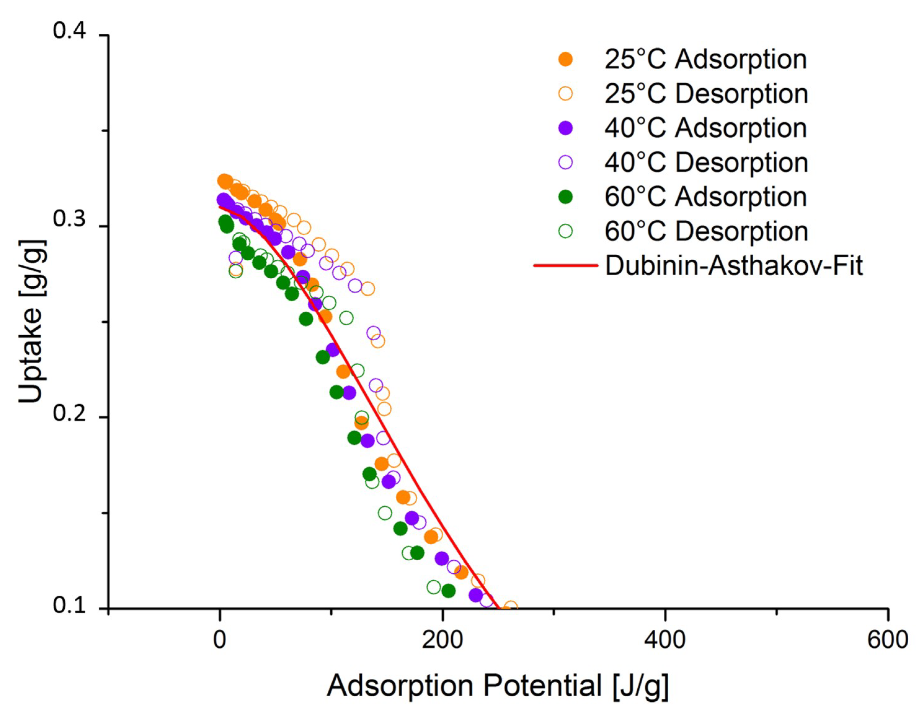
For performance calculations, a number of functions have been published, such as multi-temperature Toth [29,30], Sips [31], Dubinin [4], and others [32], which differ in complexity and suitability for different materials. For the present study, an adapted Dubinin-Asthakov-Fit (see Equation (1)) was used as it showed decent results across all materials with limited complexity. The adopted modification refers to the fact that the adsorbed vapor mass instead of the adsorbed volume is fitted to the adsorption potential (see Equation (2)). As an example, the adapted Dubinin-Asthakov-Fit for silica-gel is shown in Figure 2 (for other fits, see Supplementary Materials). The resulting coefficients can be found in Table 2 for all five materials. The specific heat capacity specified in the table corresponds to the value measured at 60 °C with a MICROSC-4C from Setaram. The bulk density was measured either directly (m) or calculated from the measured density of the powder, assuming close-packing of equal spheres with 74% of solid volume.
For determining the storage capacity of LiCl-Ver, no measured data was available at Fraunhofer ISE. Therefore, the equilibrium line and properties published by Grekova et al. [9] were adopted.
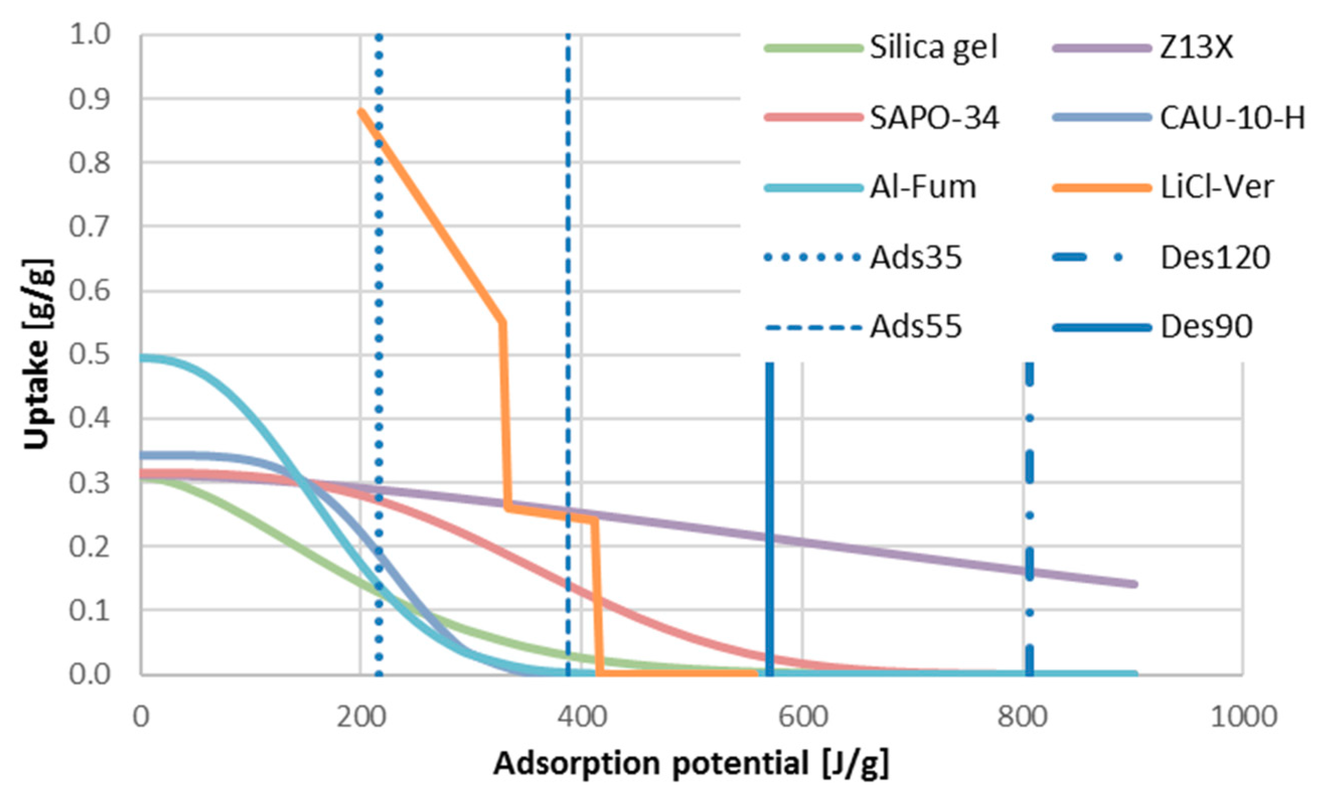
Figure 3 illustrates the resulting equilibrium curves and includes the limits of adsorption potential determined by the studied application scenarios (see Section 3). It shows that neither silica gel nor the MOFs are suitable for adsorption (discharge) at 55 °C. Zeolite 13X, on the other hand, cannot exploit much of the maximum uptake even with the maximum desorption temperature of 120 °C. LiCl-Vermiculite is entirely regenerated at 90 °C and therefore the 120 °C results are not presented in the subsequent sections.
On a material level, the storage capacity is composed of evaporation enthalpy, the adsorption energy, and the sensible heat capacity. Equation (3) (cm,max) refers to the maximum mass-specific capacity including the entire sensible heat. Equation (4) (cm,min) describes the capacity which remains after the material has entirely cooled down to the temperature of the space around the storage (assumed to be 20 °C) and which is then heated up to the adsorption (=discharging) temperature. As a simplification, a constant sensible heat capacity corresponding to the measured value at 60 °C was adopted.
For all materials but silica gel and LiCl-Ver, the ten mass-percent of the binder (cp = 1.45 kJ/kg/K, rho = 1120 kg/m3) needed to be considered for the determination of the storage capacity and environmental impact.
Temperature gradients between the heat transfer fluid and the sorbent, as they occur in real components, were ignored.
2.3. Definition of Generic Sorption Storage Configuration
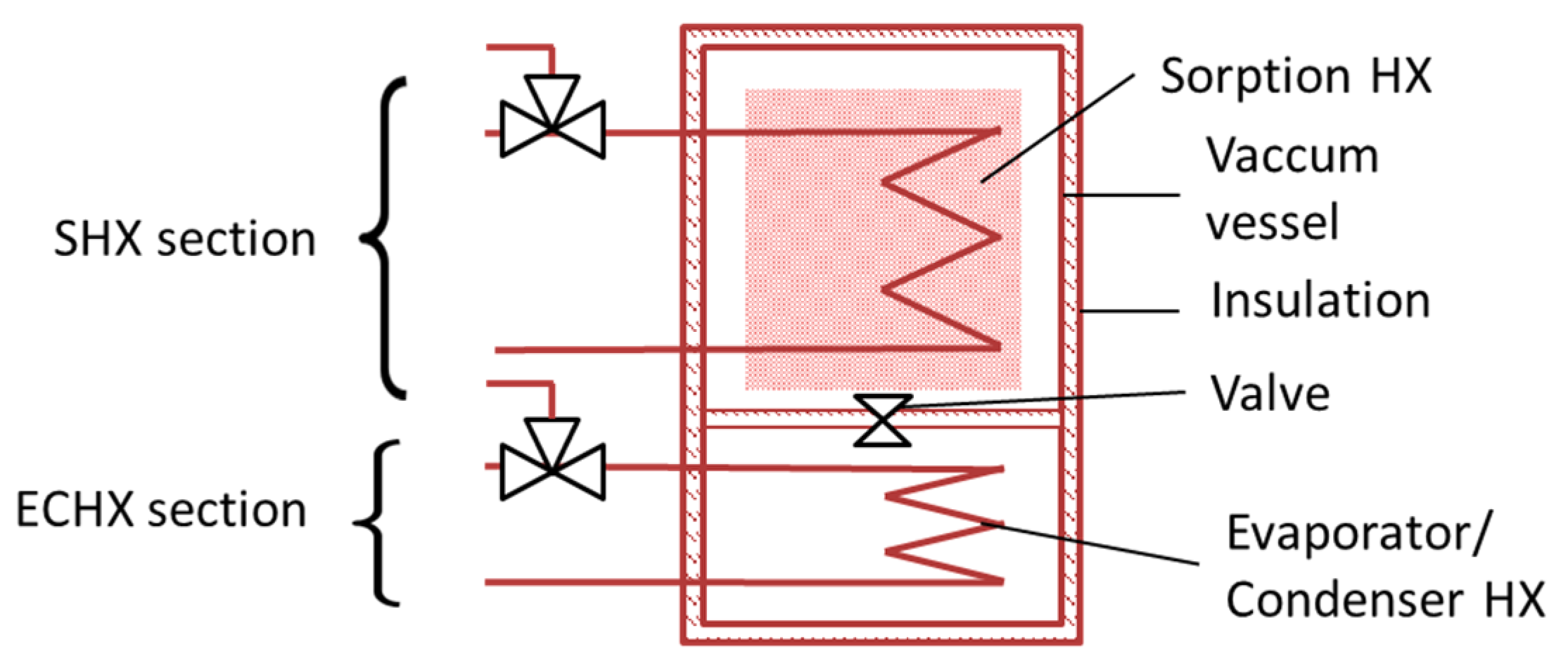
In order to evaluate the performance and life cycle impact of the sorbents related to an application, a generic storage component was defined. In this task, the experiences from past research projects and from the design of sorption chillers and heat pumps served as a good starting point. The main findings adopted, which led to a configuration as shown in Figure 4, are:
- The storage is closed, operates under near vacuum, and water is the adsorbent;
- A combined evaporator/condenser heat exchanger (ECHX) can be used since charging and discharging occur at different times;
- It is preferable to combine the sorption heat exchanger (SHX) and the evaporator/condenser heat exchanger into one containment due to easier manufacturing and better vacuum stability (compared to a solution with a separate component connected via vacuum pipework);
- A welded stainless steel containment, supported by the heat exchangers, is favorable compared to a self-baring cylindrical vacuum vessels in terms of compactness and material mass; and
- Due to the low thermal conductivity of the sorbents, a good thermal connection to the fluid is obtained by a pellet filling in a finned tube heat exchanger (staggered tubes).
2.3.1. Sorption Heat Exchanger
A parameter variation for the SHX was carried out in order to determine a configuration, which assures a rather uniform thermal conduction (meaning that the conductivity is not limited by a single thermal resistance) between the sorbent pellets and the heat transfer fluid with low material usage. Thus, the available volume for sorbent shall be maximized and the additional LCI minimized.
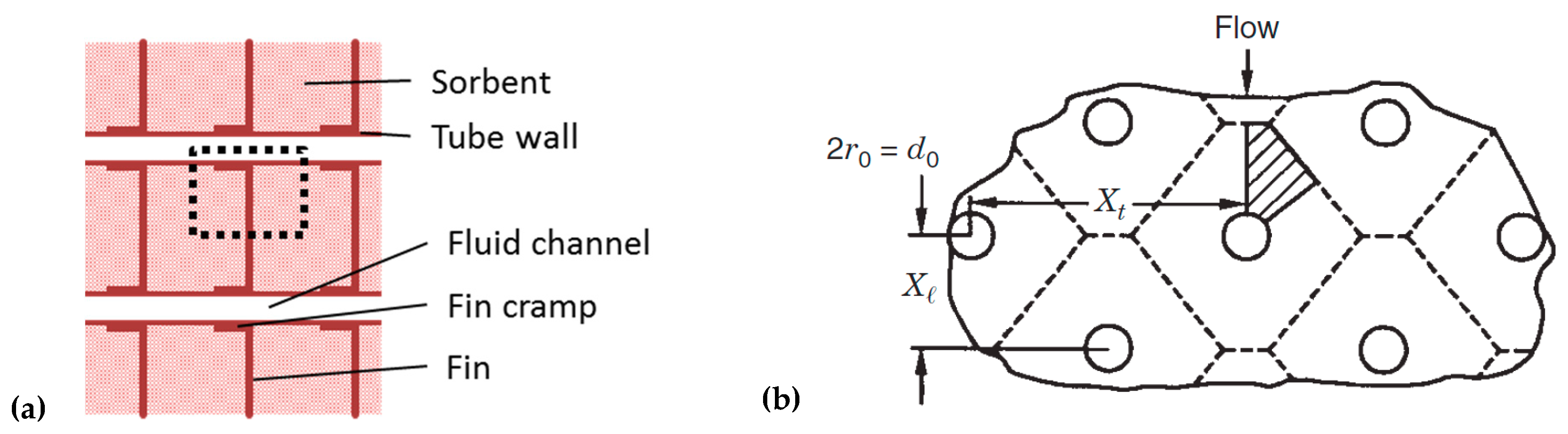
For the parameter variation, only a small but scalable representative section of the SHX—namely, a sixth of the part of a fin, which could be allocated to a single tube, including the respective sorbent volume (see Figure 5)—was calculated [33]. The varied parameters and the respective value ranges are listed in Table 3, the underlying material conductivities and contact resistances are specified in Table 4.
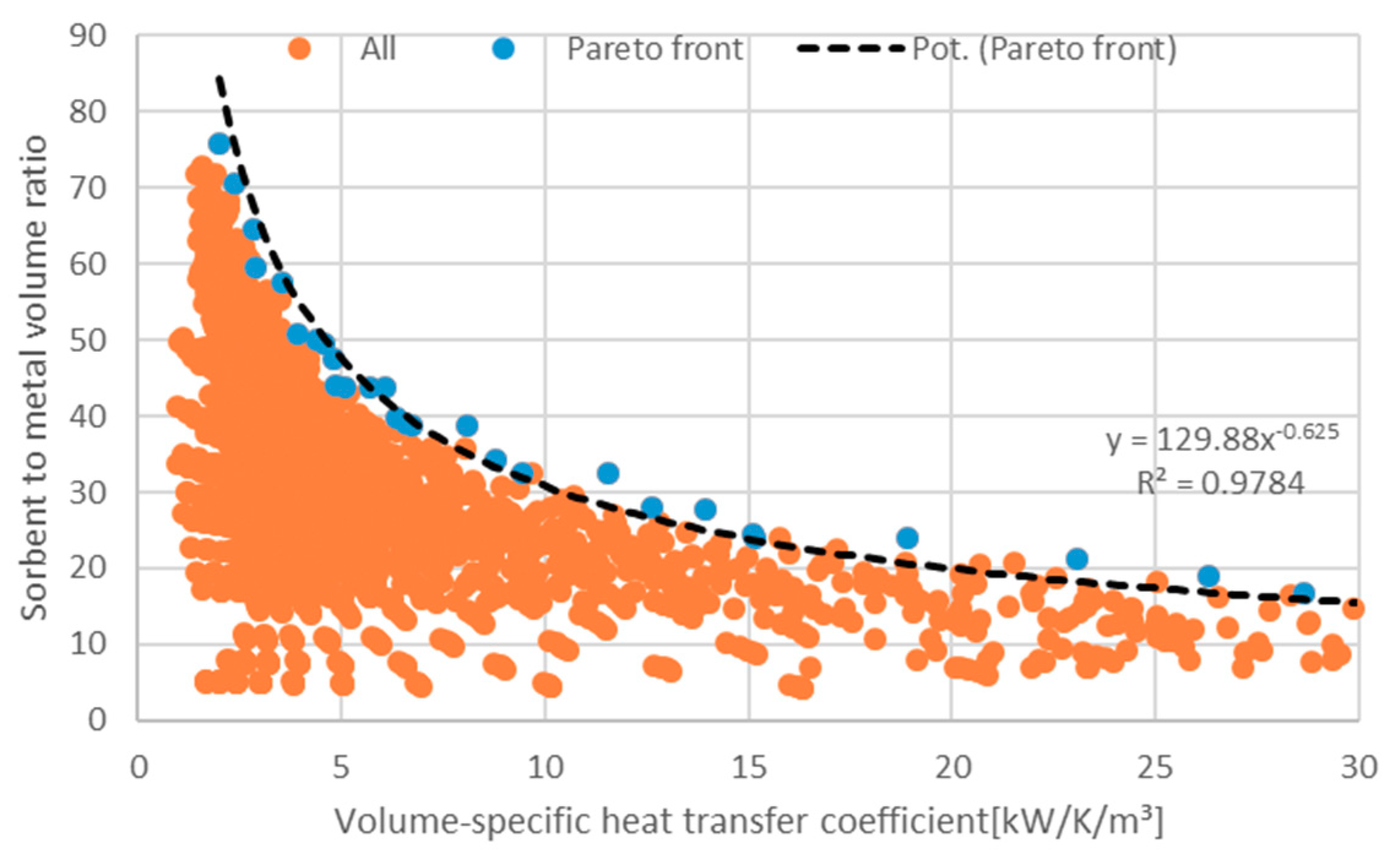
Out of the results of the parameter variation, a pareto front could be derived, which gives achievable volumetric sorbent to metal ratio for any desired heat transfer coefficient (Figure 6). Realized pilot storages have shown that a heat transfer coefficient above 1 kW/K/m3 is essential, especially for discharging with a reasonably low driving temperature difference. In order to meet this value and to account for possible imperfections in real systems compared to the calculations, a value of 3 kW/K/m3 was adopted. Thus, the volumetric sorbent to metal ratio was 65.
The analogous approach was followed for the determination of the sorbent share in the overall volume of the SHX section with a result of 94%. The remaining space corresponded to the heat transfer medium inside the SHX. To account for the necessary vapor volume, the SHX section was enlarged by 10% of the sorbent volume.
2.3.2. Evaporator/Condenser Heat Exchanger
In adsorption chillers, cycles times are typically short (<30 min), and the required refrigerant mass is limited, so their evaporator/condenser heat exchangers (ECHX) are usually designed for thin film operation. In contrast, adsorption storages require high amounts of refrigerant and have longer cycle durations. Therefore, a flooded ECHX is favorable in this application [34]. Since the condensation of refrigerant in general is a faster process than evaporation (because the entire HX surface is active), the design is oriented to the latter.
In a flooded ECHX, the evaporation mainly takes place at the contact line formed at the interface between the heat exchanger surface and the refrigerant. Therefore, the length of this line is the decisive factor for its performance. An approach for an ECHX which is scalable with the SHX dimension was derived from the configuration described in [34] (coated copper tube-fin heat exchanger). This component has three vertical tube rows, and measurements in flooded operation yielded heat transfer coefficients in the range of 50 to 20 W/K (decreasing with the filling level). The average of 35 W/K was adopted. The construction volume of the ECHX section was derived from the finned tube volume (0.083 m × 0.16 m × 0.12 m = 1.59 × 10⁻³ m3), and an additional 20% was assumed for headers and bends. Thus, the volume-specific UA-value of the ECHX section was 18.2 kW/K/m3, excluding any additional vapor volume.
3. Results and Discussion
3.1. Results on the Material Level
3.1.1. Environmental Impact of the Materials
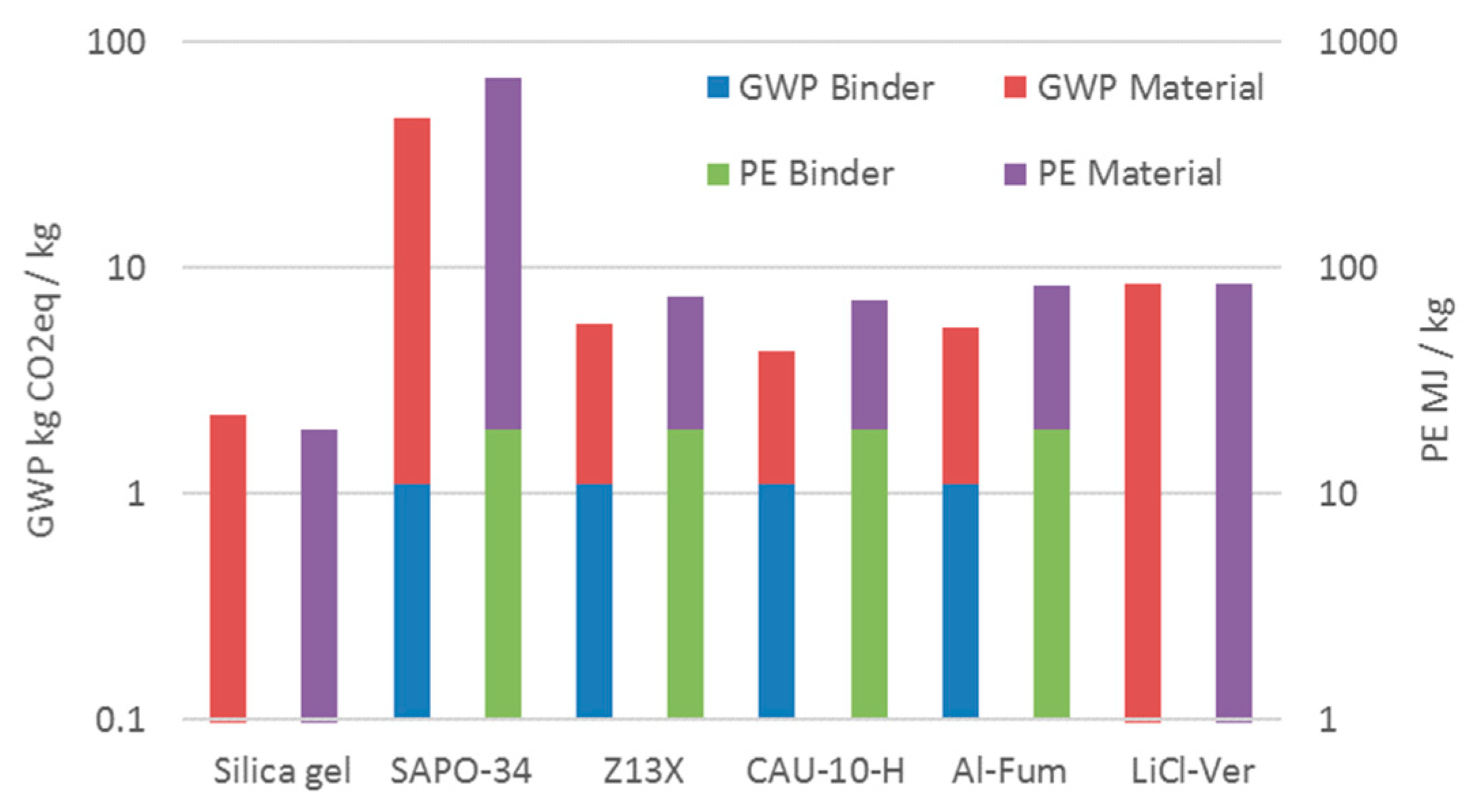
Figure 7 shows the environmental impact of the materials according to the two selected categories, GWP and PE. Qualitatively they show a similar trend. The absolute impact of the binder was constant among the materials due to the fixed mass-specific share. The relative share was below 3% for SAPO-34 and approximately one-third for the other binder-containing materials, independent of the impact category. Due to this analogy, in the following sections, only the GWP category will be evaluated. A tabular overview on all the values the result chapter relies on is available in the Appendix A.
3.1.2. Material Storage Capacity
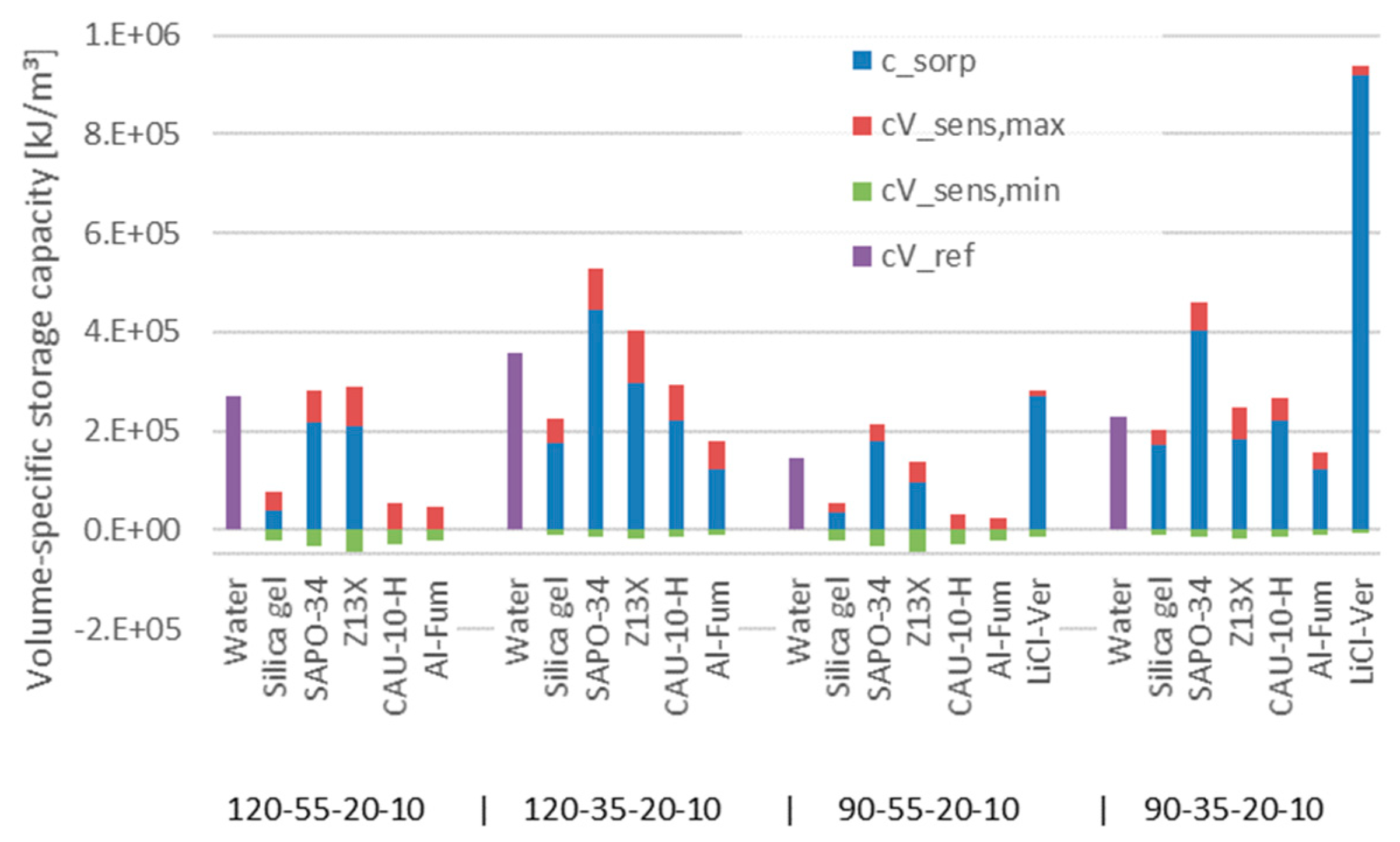
The volumetric storage capacity was calculated based on the material data provided in Table 2 and Equations (3) and (4). The results for the four considered scenarios (35 °C and 55 °C adsorption, corresponding to underfloor and radiator heating, and 90 °C and 120 °C desorption temperature, respectively; condensation and evaporation temperature were fixed at 20 °C and 10 °C, respectively; and temperature gradients in heat exchangers were neglected) are depicted in Figure 8.
For ideal short-term storage (discharge begins immediately after charging, so no sensible heat is lost), the sum of sorptive and maximum sensible capacity must be considered. This value can be compared directly to the reference capacities of water (also loss-free, with a useful capacity between ad- and de-sorption temperatures). Interestingly, the regular sorption materials rarely outperformed water in terms of volumetric density. Especially for the 35 °C cases, SAPO-34 reached the storage capacities noticeably above that of the reference. LiCl-Vermiculite significantly outperformed the remaining materials with a volumetric storage capacity up to four times that of water.
Since 120 °C as maximum temperature for water storages means additional effort for pressure-resistant systems, the 90 °C bars can be adopted as references as well, which improves the perspectives of sorption storage.
For longer term storage, the resulting storage capacity can be obtained by adding the (negative) green bar, which represents the energy required to heat the sorbent from ambient to adsorption temperature, to the sorptive capacity. In this case, the effective capacity of the water storage will also be lower and needs to be corrected by an appropriate efficiency [35]. Assuming, for example, 50% sensible losses for the water storage and 100% sensible losses for the sorption alternatives due to less insulation, some more sorption storages show benefits compared to water.
The fact that the MOFs did not show any sorptive capacity for the 55 °C cases can be explained by Figure 2: At that temperature, they were still entirely desorbed.
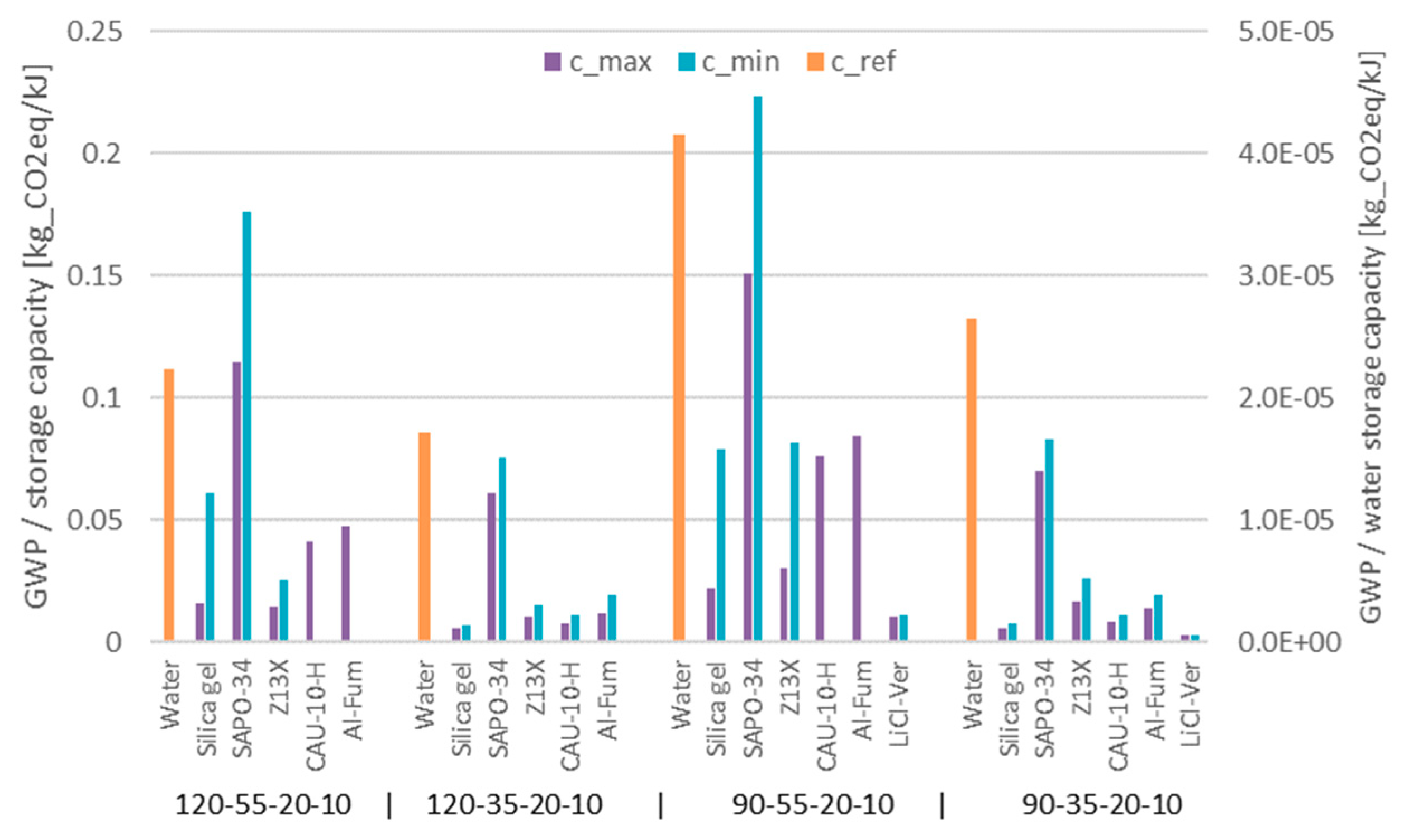
3.1.3. Impact per Storage Capacity on the Material Level
After their separate analysis, the storage capacity and the environmental impact were combined (Figure 9) in order to understand the specific impact of each sorbent. Due to its high GWP, SAPO-34 had the highest specific impact of several thousand times higher than that of water. This held true even in the 35 °C cases, in which it appeared rather favorable in the preceding storage capacity section. For silica gel and the MOFs in 35 °C cases, the multiplier lies in the range of various hundreds. The salt-composite showed the best result in these scenarios, with an impact ~120 higher than that of water (Tdes = 90 °C).
3.2. Results on Component Level
The evaluation on component level takes a 1 m3 storage volume (excluding insulation) as the reference. In the case of the water storage, this was a market-average steel cylinder with a mass of 147.5 kg and 10 cm mineral wool insulation [36]. The sorption storage was assumed to be a cube with a 1 m edge length and made of 1 mm stainless steel sheets plus 3.5 cm of insulation.
3.2.1. Component Storage Capacity
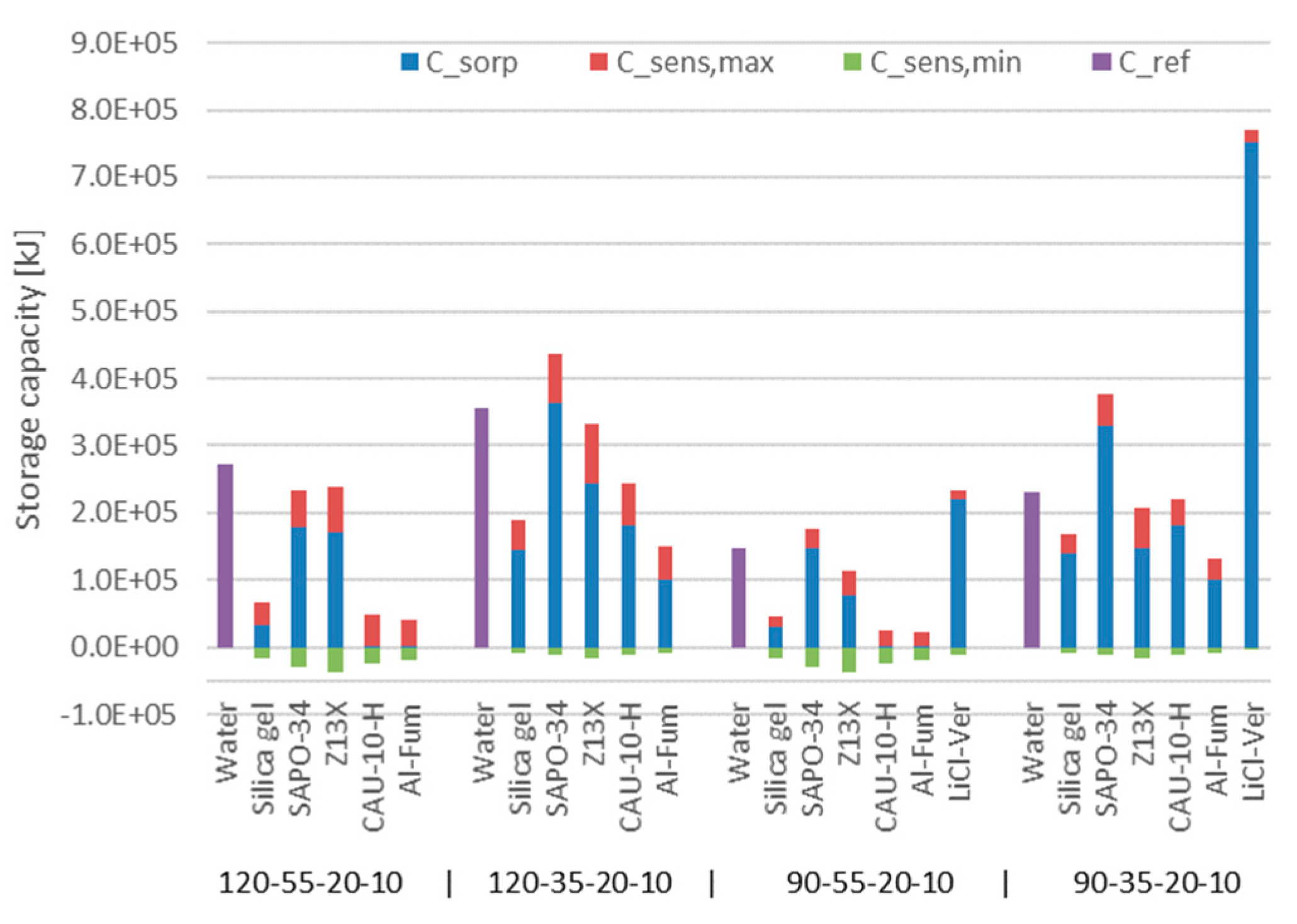
The storage capacity for the 1 m3 reference volume is presented in Figure 10. The values for water correspond to those in Figure 8, since a water storage requires no built-in components. The sorption storages show lower capacities because the entire volume was not available for sorbents. The ECHX was considered as entirely inactive in terms of storage capacity while the SHX contributed to the sensible share. Based on the sorbent-to-metal and sorbent-to-total-sorption-section volume ratios as well as the resulting geometry of an adapted ECHX, the available volume for sorbent pellets was 0.819 m3. The SHX had a material volume of 12.6 L and the ECHX had a material volume of 2.9 L and a construction volume of 43 L. Table 5 lists the corresponding sorbent pellet masses and the resulting mass ratios. The vapor volume was assumed to constitute 10% of the volume not occupied by heat exchangers and the sorbent.
Thus, considering idealized, loss-free short-term storage, among the typical sorbents, only the zeolite SAPO-34 showed a higher storage density on component level compared to water. The outstanding sorption-like LiCl-Vermiculite achieved a storage density ~3.5 higher than that of water. Assuming long-term storage as above (50% sensible losses for the water storage and 100% sensible losses for the sorption alternatives), some more sorption storages showed benefits compared to water. Even then, their relative storage densities compared to water remained below two.
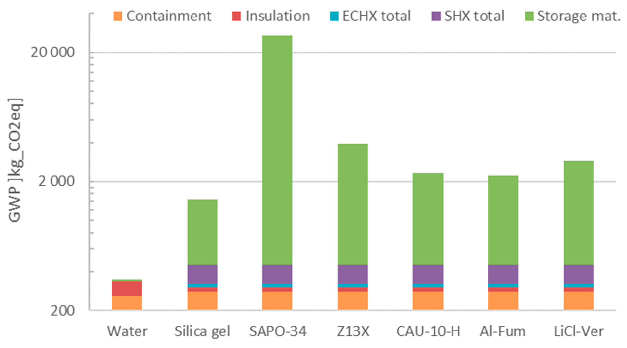
3.2.2. Environmental Impact of the Storage Component
Figure 11 breaks up the GWP of the resulting 1 m3 storages by the main parts. Interestingly, the steel cylinder for the water storage with a mass of 147.5 kg and the stainless steel housing of the sorption storages (47.4 kg) had a very similar impact due to the higher specific impact of the latter metal. The thicker insulation of the water storage evidently resulted in a higher absolute GWP. The water itself had a negligible impact. The SHX contributed about half the GWP of the containment, and the ECHX contributed roughly another 10%. The sorbents accounted for the major share of the overall GWP: From 69%, in case of silica gel, up to 98% for SAPO-34.
3.2.3. Impact per Storage Capacity on the Component Level
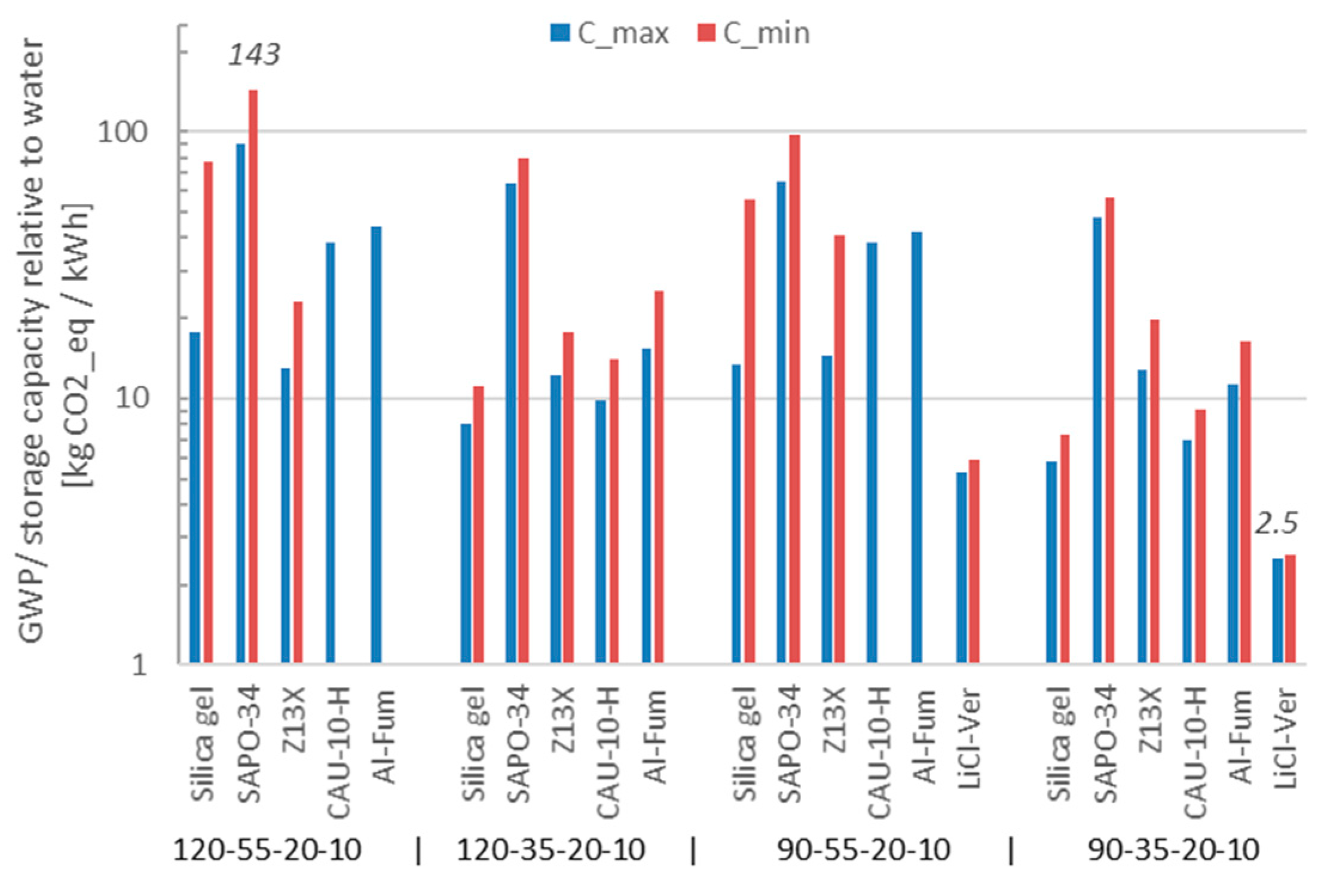
In order to determine the overall environmental impact, the impact factors of the standard materials (metals and insulation) were extracted from the Gabi database [36] and summed to the sorbent values. Figure 12 links the storage capacity to the resulting overall global warming potential of the sorption components, normalized to the respective results for the water storage.
The impact of a storage with composite material was higher compared to the water reference by a factor of ~2.5, and classical sorption materials showed minimum factors around 10. In the worst case (SAPO-34), the factor went up to ~100. Assuming a 90 °C maximum reference storage temperature for the 120 °C desorption temperature scenarios, 120 °C results can be reduced to ~50% and ~65%, respectively, for 55 °C and 35 °C adsorption temperature ((90 °C–55 or 35 °C)/(120 °C–55 or 35 °C)).
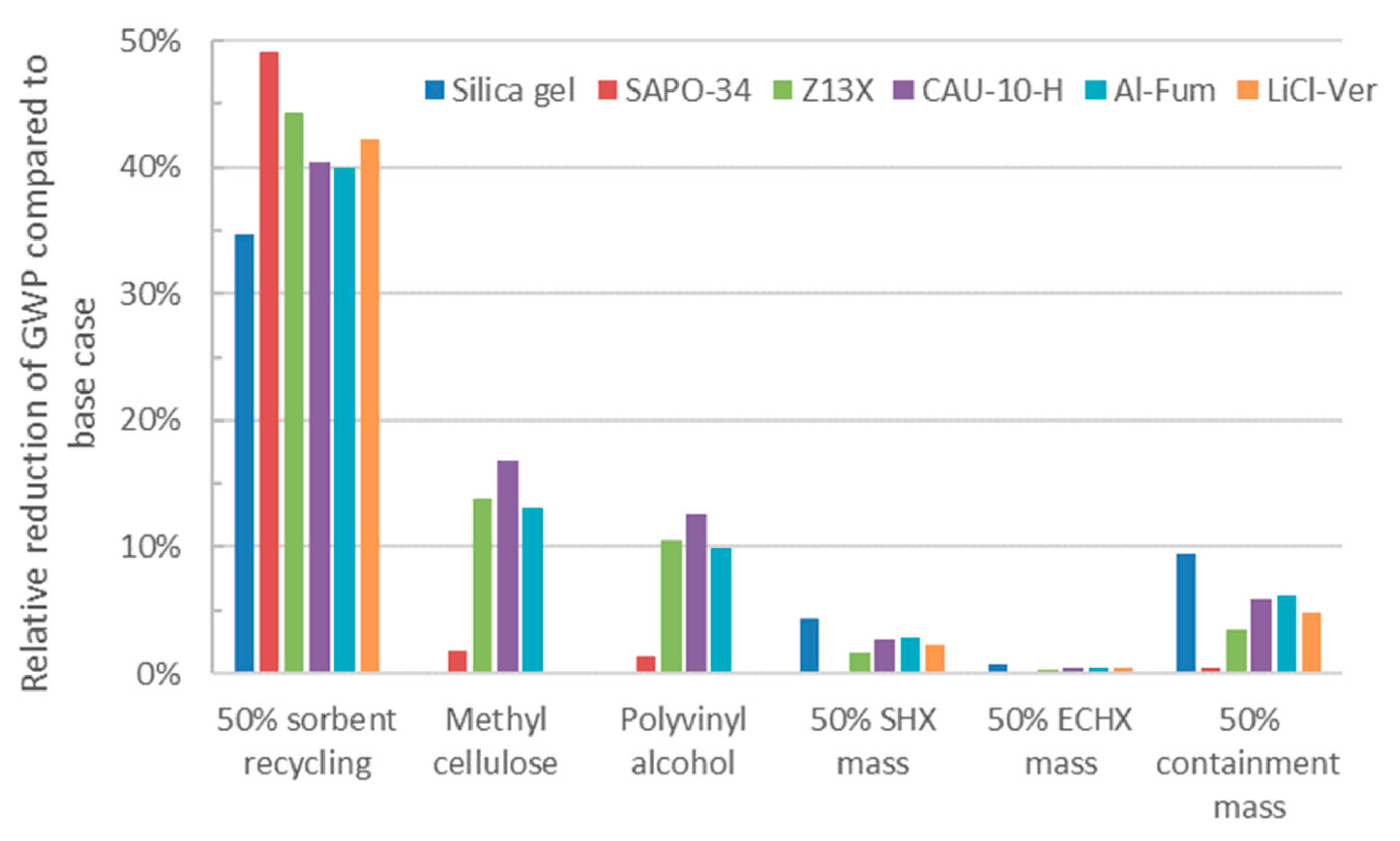
3.2.4. Sensitivity Analysis
In order to get an impression on the sensitivity of the above results to the single inputs and assumptions, Figure 13 shows their sensitivity to certain variations. The reduction of the material impact evidently had the largest impact. Assuming that 50% of it can be recycled after the useful lifetime of the storage and ignoring any additional effort for dismantling or reconditioning, the GWP of the storages dropped by between ~35% (silica gel) and 48% (SAPO-34).
Replacing the energy-intensively produced silicon-based binder by common but less water-resistant organic alternatives, methylcellulose and polyvinyl alcohol, also showed benefits of up to 15% depending on its relative impact. Reducing the metal mass, be it in the SHX, ECHX, or the containment, also yielded a GWP decrease.
4. Conclusions
The storage capacity and environmental impact (in terms of GWP) of five classical sorbents and one sorbent-like material regarded promising for application in heat storages for building applications were studied.
On the material level, it turned out that the storage capacity of classical sorbents under four application scenarios was lower compared to water than that commonly reported in literature, even though temperature gradients occurring in real applications have been neglected. Among them, SAPO-34 showed the best performance and reached capacity factors between 2 and 4 compared to water, depending on the assumed boundary conditions values. Silica gel and the MOFs turned out to be unsuitable for 55 °C heating applications, as they were not able to adsorb significant amounts of water vapor at this temperature. The sorbent-like salt-composite (LiCl-Vermiculte) showed the highest volumetric storage capacity, roughly twice that of SAPO-34.
At the same time, the manufacturing of all materials leads to environmental impacts much higher than that of water. Again, SAPO-34 stood out of the mass, this time because of its very significant impact, approximately 10 times higher than that of the zeolite, the MOFs, and the composite, and almost 30 times higher than that of silica gel. The specific impact per storage capacity of the storage materials was above around one hundred (LiCl-Vermiculite) to several thousands (SAPO-34) times higher than that of water.
The subsequent evaluation on the component level, which includes auxiliary parts required for the exploitation of the storage potentials, such as containment, insulation, and heat exchangers, brings the results closer to an actual application. A 1 m3 containment volume was chosen as the reference. The volumetric storage density of the sorption variants was further decreased by these additional components. It still reached a factor of ~7 for the salt-composite but was only 2.5 times higher than that of water in the best case of SAPO-34. The environmental impact of all storage types suffered from the incorporation of the additional components. The specific impact of sorption storages was about 2.5 to 100 times higher than that of water. Only with very optimistic (and not necessarily realistic) assumptions such as recycling of the sorbent pellets, highly efficient and light-weight auxiliary components, and long term storage which makes water storages a very lossy alternative, can an environmental benefit compared to this reference seem possible.
The presented findings suggest that the chances that closed adsorption storages in building applications can provide an environmental benefit are small. When a significant increase of storage capacity compared to water is required, salt-composites are an option under the preconditions that, for the entire aspired useful life time, salt leakage (also due to condensation) and corrosion can be eliminated. For the classical sorbents, more promising applications should fulfill the following conditions:
- Better exploitation of the potential uptake of the sorbent;
- Seek applications where (non-pressurized) water storage cannot serve as benchmark, e.g., due to temperature limitations; and
- Minimize the amount and mass of auxiliary equipment.
For new material developments, the presented methodology may provide guidance during the selection and optimization of raw materials and production routes in order to minimize the environmental impact. Further thermochemical storage materials such as liquid sorbents still need to be evaluated, yet it is likely that they face similar challenges to solid sorbents.
Supplementary Materials
Supplementary File 1Author Contributions
D.F. and T.H. prepared the material data for the LCIA performed by R.H. and the performance calculations conducted by B.N.; B.N. conceived the study under guidance of P.S. and G.M. and drafted the manuscript with input from the above named authors to the respective sections. All authors read and approved the final manuscript.
Funding
This research was funded by the Germany Federal Ministry of Economic Affairs and Energy and supported by Project Management Jülich under grant number 03ET1333.
Conflicts of Interest
The authors declare no conflict of interest. The funders had no role in the design of the study; in the collection, analyses, or interpretation of data; in the writing of the manuscript, and in the decision to publish the results.
Nomenclature
| Symbol | Description | Unit |
| A | Adsorption Potential | J/g |
| b | Characteristic Dubinin-Astakhov Parameter | kg/J |
| c m,max | maximum specific heat capacity (loss-free) | J/kg/K |
| c m,min | minimum specific heat capacity (100% sensible losses) | J/kg/K |
| c p | specific isobaric heat capacity | J/kg/K |
| d fin | fin thickness | m |
| d sp,fin | fin spacing | m |
| d sp,tb | tube spacing | m |
| d tb | tube diameter | m |
| h evap | evaporation enthalpy | kJ/kg |
| n | exponent | - |
| saturation pressure | Pa | |
| actual pressure at sorbens temperature | Pa | |
| R | Ideal gas constant of water vapor | J/kg/K |
| r fin,tb | Resistance at | W/m2/K |
| r sorb,fin | W/m2/K | |
| T Ads | Adsorption temperature | K |
| T amb | Ambient temperature | K |
| T Des | Desorption temperature | K |
| T sorb | Sorbens temperature | K |
| X | Sorbent uptake | g/g |
| X | uptake | g/g |
| X0 | Maximum sorbent uptake | g/g |
| λ fin | Fin thermal conductivity | W/m/K |
| λ sorb | Sorbent thermal conductivity | W/m/K |
| λ tb | Tube thermal conductivity | W/m/K |
Appendix A

Table A1.
Overview on material properties and life cycle impact values used for calculations.
| Material | Density | Sensible Heat Capacity | GWP | PE |
|---|---|---|---|---|
| (kg/m3) | (kJ/kg/K) | (kg CO2eq/kg) | (MJ/kg) | |
| Silica gel | 546 | 1.0 | 2.3 | 19.3 |
| SAPO-34 | 650 | 1.4 | 50.2 | 745.3 |
| Z13X | 704 | 1.7 | 5.1 | 62.0 |
| CAU-10-H | 466 | 1.6 | 3.5 | 58.1 |
| Al-Fum | 316 | 1.7 | 4.8 | 70.9 |
| LiCl-Ver | 350 | 1.0 | 8.5 | 85.4 |
| Water | 1000 | 4.2 | 0.0 | 0.06 |
| Silicon-based binder | 1120 | 1.5 | 11.1 | 191.9 |
| Methylcellulose | 1260 | 1.5 | 1.4 | - |
| Polyvinyl alcohol | 1190 | 1.5 | 3.6 | - |
| Copper | 8940 | - | 1.1 | - |
| Mineral wool | 80 | - | 1.4 | - |
| Steel | 7860 | - | 1.8 | - |
| Stainless steel | 8940 | - | 5.9 | - |
References
- Arce, P.; Medrano, M.; Gil, A.; Oró, E.; Cabeza, L.F. Overview of thermal energy storage (TES) potential energy savings and climate change mitigation in Spain and Europe. Appl. Energy 2011, 88, 2764–2774. [Google Scholar] [CrossRef]
- Aydin, D.; Casey, S.P.; Riffat, S. The latest advancements on thermochemical heat storage systems. Renew. Sustain. Energy Rev. 2015, 41, 356–367. [Google Scholar] [CrossRef]
- Scapino, L.; Zondag, H.A.; van Bael, J.; Diriken, J.; Rindt, C.C.M. Sorption heat storage for long-term low-temperature applications: A review on the advancements at material and prototype scale. Appl. Energy 2017, 190, 920–948. [Google Scholar] [CrossRef]
- Stach, H.; Mugele, J.; Jänchen, J.; Weiler, E. Influence of Cycle Temperatures on the Thermochemical Heat Storage Densities in the Systems Water/Microporous and Water/Mesoporous Adsorbents. Adsorption 2005, 11, 393–404. [Google Scholar] [CrossRef]
- Zettl, B.; Englmair, G.; Somitsch, W. An Open Sorption Heat Storage Concept and Materials for Building Heat Supply. Energy Procedia 2015, 73, 297–304. [Google Scholar] [CrossRef]
- Frazzica, A.; Freni, A. Adsorbent working pairs for solar thermal energy storage in buildings. Renew. Energy 2017, 110, 87–94. [Google Scholar] [CrossRef]
- Jänchen, J.; Ackermann, D.; Stach, H.; Brösicke, W. Studies of the water adsorption on Zeolites and modified mesoporous materials for seasonal storage of solar heat. Sol. Energy 2004, 76, 339–344. [Google Scholar] [CrossRef]
- Jeremias, F.; Lozan, V.; Henninger, S.K.; Janiak, C. Programming MOFs for water sorption: Amino-functionalized MIL-125 and UiO-66 for heat transformation and heat storage applications. Dalton Trans. 2013, 42, 15967–15973. [Google Scholar] [CrossRef]
- Grekova, A.D.; Gordeeva, L.G.; Aristov, Y.I. Composite “LiCl/vermiculite” as advanced water sorbent for thermal energy storage. Appl. Therm. Eng. 2017, 124, 1401–1408. [Google Scholar] [CrossRef]
- Gaeini, M.; Rouws, A.L.; Salari, J.W.O.; Zondag, H.A.; Rindt, C.C.M. Characterization of microencapsulated and impregnated porous host materials based on calcium chloride for thermochemical energy storage. Appl. Energy 2018, 212, 1165–1177. [Google Scholar] [CrossRef]
- Permyakova, A.; Skrylnyk, O.; Courbon, E.; Affram, M.; Wang, S.; Lee, U.-H.; Valekar, A.H.; Nouar, F.; Mouchaham, G.; Devic, T.; et al. Synthesis Optimization, Shaping, and Heat Reallocation Evaluation of the Hydrophilic Metal-Organic Framework MIL-160(Al). ChemSusChem 2017, 10, 1419–1426. [Google Scholar] [CrossRef] [PubMed]
- Bales, C.; Gantenbein, P.; Jaenig, D.; Kerskes, H.; van Essen, M.; Weber, R. Final Report of IEA SHC Task 32 Subtask B—“Chemical and Sorption Storage”; IEA Solar Heating and Cooling Programme: Paris, France, 2008. [Google Scholar]
- SolSpaces—Entwicklung und Erprobung Einer Autarken Solaren Wärmeversorgung für Energieeffiziente Kompaktgebäude. Available online: http://www.itw.uni-stuttgart.de/forschung/projekte/abgeschlossen/solspaces.html (accessed on 29 August 2018).
- Scapino, L.; Zondag, H.A.; van Bael, J.; Diriken, J.; Rindt, C.C.M. Energy density and storage capacity cost comparison of conceptual solid and liquid sorption seasonal heat storage systems for low-temperature space heating. Renew. Sustain. Energy Rev. 2017, 76, 1314–1331. [Google Scholar] [CrossRef]
- Munz, G.; Jeremias, F.; Krämer, B.; Wolff, T.; Henninger, S.K. Adsorbents for Seasonal Heat Storage—Economical and Energetic Assessment; Deutsche Zeolith Tagung: Gießen, Germany, 2016. [Google Scholar]
- Vasta, S.; Brancato, V.; La Rosa, D.; Palomba, V.; Restuccia, G.; Sapienza, A.; Frazzica, A. Adsorption Heat Storage: State-of-the-Art and Future Perspectives. Nanomaterials 2018, 8, 522. [Google Scholar] [CrossRef] [PubMed]
- Horn, R.; Burr, M.; Fröhlich, D.; Gschwander, S.; Held, M.; Lindner, J.P.; Munz, G.; Nienborg, B.; Schossig, P. Life Cycle Assessment of Innovative Materials for Thermal Energy Storage in Buildings. Procedia CIRP 2018, 69, 206–211. [Google Scholar] [CrossRef]
- Bertsch, F. Umsetzung und Bewertung der Thermochemischen Energiespeicherung für die Solare Gebäudebeheizung. Ph.D. Thesis, University of Stuttgart, Stuttgart, Germany, 2014. [Google Scholar]
- Deutsches Institut für Normung. DIN EN ISO 14044:2018-05 Environmental Management—Life Cycle Assessment—Requirements and Guidelines; Beuth Verlag GmbH: Berlin, Germany, 2018. [Google Scholar]
- Deutsches Institut für Normung. DIN EN ISO 14040:2009-11 Environmental Management—Life Cycle Assessment—Principles and Framework; Beuth Verlag GmbH: Berlin, Germany, 2009. [Google Scholar]
- Deutsches Institut für Normung. DIN EN 15978:2012-10 Sustainability of Construction Works—Assessment of Environmental Performance of Buildings—Calculation Method; Beuth Verlag GmbH: Berlin, Germany, 2012. [Google Scholar]
- Deutsches Institut für Normung. DIN EN 15804:2014-07 Sustainability of Construction Works—Environmental Product Declarations—Core Rules for the Product Category of Construction Products; Beuth Verlag GmbH: Berlin, Germany, 2014. [Google Scholar]
- Fantke, P. UNEP/SETAC Scientific Consensus Model for Characterizing Human Toxicological and Ecotoxicological Impacts of Chemical Emissions in Life Cycle Assessment; USEtox® International Center Hosted at the Technical University of Denmark: Lyngby, Demark, 2017. [Google Scholar]
- Newalkar, B.L.; Komarneni, S. Synthesis and Characterization of Microporous Silica Prepared with Sodium Silicate and Organosilane Compounds. J. Sol-Gel Sci. Technol. 2000, 18, 191–198. [Google Scholar] [CrossRef]
- Liu, G.; Tian, P.; Li, J.; Zhang, D.; Zhou, F.; Liu, Z. Synthesis, characterization and catalytic properties of SAPO-34 synthesized using diethylamine as a template. Microporous Mesoporous Mater. 2008, 111, 143–149. [Google Scholar] [CrossRef]
- De Lucas, A.; Uguina, M.A.; Covian, I.; Rodriguez, L. Synthesis of 13X zeolite from calcined kaolins and sodium silicate for use in detergents. Ind. Eng. Chem. Res. 1992, 31, 2134–2140. [Google Scholar] [CrossRef]
- Lenzen, D.; Bendix, P.; Reinsch, H.; Fröhlich, D.; Kummer, H.; Möllers, M.; Hügenell, P.P.C.; Gläser, R.; Henninger, S.; Stock, N. Scalable Green Synthesis and Full-Scale Test of the Metal-Organic Framework CAU-10-H for Use in Adsorption-Driven Chillers. Adv. Mater. 2018, 30. [Google Scholar] [CrossRef]
- Leung, E.; Müller, U.; Trukhan, N.; Mattenheimer, H.; Cox, G.; Blei, S. Process for Preparing Porous Metal-Organic Frameworks Based on Aluminum Fumarate. US Patent 8,524,932 B2, 30 September 2011. [Google Scholar]
- Wang, Y.; LeVan, M.D. Adsorption Equilibrium of Carbon Dioxide and Water Vapor on Zeolites 5A and 13X and Silica Gel: Pure Components. J. Chem. Eng. Data 2009, 54, 2839–2844. [Google Scholar] [CrossRef]
- Onyango, M.S.; Kojima, Y.; Aoyi, O.; Bernardo, E.C.; Matsuda, H. Adsorption equilibrium modeling and solution chemistry dependence of fluoride removal from water by trivalent-cation-exchanged zeolite F-9. J. Colloid Interface Sci. 2004, 279, 341–350. [Google Scholar] [CrossRef]
- Gorbach, A.; Stegmaier, M.; Eigenberger, G. Measurement and Modeling of Water Vapor Adsorption on Zeolite 4A—Equilibria and Kinetics. Adsorption 2004, 10, 29–46. [Google Scholar] [CrossRef]
- Foo, K.Y.; Hameed, B.H. Insights into the modeling of adsorption isotherm systems. Chem. Eng. J. 2010, 156, 2–10. [Google Scholar] [CrossRef]
- Shah, R.K.; Sekulić, D.P. Fundamentals of Heat Exchanger Design; Wiley-Interscience: Hoboken, NJ, USA, 2003. [Google Scholar]
- Volmer, R.; Eckert, J.; Füldner, G.; Schnabel, L. Evaporator development for adsorption heat transformation devices—Influencing factors on non-stationary evaporation with tube-fin heat exchangers at sub-atmospheric pressure. Renew. Energy 2017, 110, 141–153. [Google Scholar] [CrossRef]
- Data Measurement and Analysis of a Solar Heating System with Seasonal Storage. Energy Procedia 2015, 70, 241–248. [CrossRef]
- Gabi Product Databases; Thinkstep AG: Stuttgart, Germany, 2018.
Figure 1.
Schematic visualization of the life cycle of a product. Source: University of Stuttgart.

Figure 2.
Plot of the water sorption isotherms of silica gel at different temperatures during ad- and desorption. The red line depicts the adapted Dubinin-Asthakov-Fit; data points and fits for other materials are provided in the Supplementary Materials.
Figure 2.
Plot of the water sorption isotherms of silica gel at different temperatures during ad- and desorption. The red line depicts the adapted Dubinin-Asthakov-Fit; data points and fits for other materials are provided in the Supplementary Materials.

Figure 3.
Plot of the adapted Dubinin-Astakhov-Regressions and the LiCl-Ver equilibrium line used to determine the water uptake (and finally storage capacity) of the considered thermo-chemical materials (TCMs). The vertical lines indicate the applicable limits of adsorption potential for the studied scenarios (35 °C and 55 °C adsorption and 90 °C and 120 °C desorption temperature, respectively; condensation and evaporation temperature are fixed at 20 °C and 10 °C, respectively).

Figure 4.
Schematic of the considered storage configuration.

Figure 5.
(a) A cross-cut along the heat exchanger tubes; the dotted line delimits the section calculated as sorber. (b) A plan view of one fin; the shaded area corresponds to the resulting hexagon when dividing fins with the sector method (Source: Shat et al.).
Figure 5.
(a) A cross-cut along the heat exchanger tubes; the dotted line delimits the section calculated as sorber. (b) A plan view of one fin; the shaded area corresponds to the resulting hexagon when dividing fins with the sector method (Source: Shat et al.).

Figure 6.
Results of the parameter variation for the SHX; blue dots correspond to the identified Pareto front.
Figure 6.
Results of the parameter variation for the SHX; blue dots correspond to the identified Pareto front.

Figure 7.
Environmental impact of the storage materials per kg of material (logarithmic scales).

Figure 8.
Volumetric storage capacity of the selected materials for two different de- and adsorption temperatures (specified below material names in the following order; Tdes-Tads-Tcond-Tevap).
Figure 8.
Volumetric storage capacity of the selected materials for two different de- and adsorption temperatures (specified below material names in the following order; Tdes-Tads-Tcond-Tevap).

Figure 9.
Global warming potential per storage capacity of selected materials (left axis: sorption materials; right axis: water) for different boundary conditions (Tdes-Tads-Tcond-Tevap); for MOFs and Tads = 55 °C, c min is negative, so no values are shown.
Figure 9.
Global warming potential per storage capacity of selected materials (left axis: sorption materials; right axis: water) for different boundary conditions (Tdes-Tads-Tcond-Tevap); for MOFs and Tads = 55 °C, c min is negative, so no values are shown.

Figure 10.
Storage capacity of 1 m3 storages with the selected materials under different boundary conditions (Tdes-Tads-Tcond-Tevap).
Figure 10.
Storage capacity of 1 m3 storages with the selected materials under different boundary conditions (Tdes-Tads-Tcond-Tevap).

Figure 11.
GWP of the single storage component elements (for 1 m3 storages).

Figure 12.
GWP per storage capacity of sorption storages under different boundary conditions (Tdes-Tads-Tcond-Tevap) compared to water.
Figure 12.
GWP per storage capacity of sorption storages under different boundary conditions (Tdes-Tads-Tcond-Tevap) compared to water.

Figure 13.
Influence of different measures on GWP of the studied storage configurations.

Table 1.
Overview on investigated sorption materials; MOF: Metal Organic Framework.
| Material Name | Short Name | Type | Reference for Production Process |
|---|---|---|---|
| Silica gel (microporous) | Silica gel | Xerogel | [24] |
| Silica-aluminophosphate 34 | SAPO-34 | Zeolite-like | [25] |
| Zeolite type 13X | Z13X | Zeolite | [26] |
| CAU-10-H | CAU-10-H | MOF | [27] |
| Aluminum-Fumarate | Al-Fum. | MOF | [28] |
| Vermiculite impregnated with Lithiumchloride | LiCl-Ver | Composite/sorption-like | [9] |
Table 2.
Key information on the investigated materials; measured (m) and calculated (c) from the measured density of the powder, assuming close-packing of equal spheres with 74% of solid volume.
Table 2.
Key information on the investigated materials; measured (m) and calculated (c) from the measured density of the powder, assuming close-packing of equal spheres with 74% of solid volume.
| Material | X0 (g/g) | b (g/J) | N | cp,sorb,60 °C (J/kg/K) | Bulk Density 1 (kg/m3) |
|---|---|---|---|---|---|
| Silica gel | 0.31 | 232.8 | 1.673 | 1.04 | 545.6 (m) |
| SAPO-34 | 0.315 | 415.9 | 2.9220 | 1.42 | 650.0 (c) |
| Z13X | 0.321 | 1404.0 | 1.2350 | 1.68 | 703.5 (m) |
| CAU-10-H | 0.343 | 244.5 | 4.1510 | 1.59 | 466.0 (c) |
| Al-Fum. | 0.496 | 195.6 | 2.3860 | 1.67 | 316.3 (m) |
| LiCl-Ver | - | - | - | 1.01 | 350.0 |
1 Bulk density refers to pellets (not powder).
Table 3.
Value range for tube diameter and spacing as well as fin thickness and spacing covered during parameter variation.
Table 3.
Value range for tube diameter and spacing as well as fin thickness and spacing covered during parameter variation.
| Description | d tb (m) | d sp,tb (m) | d fin (m) | d sp,fin (m) |
|---|---|---|---|---|
| Minimum | 0.006 | 0.001 | 10-4 | 0.0015 |
| Maximum | 0.016 | 0.005 | 2 × 10⁻⁴ | 0.0215 |
| Increment | 0.002 | 0.0005 | 2.5 × 10⁻⁵ | 0.002 |
Table 4.
Heat conductivity parameters of the heat exchanger.
| λ fin (W/m/K) | λ tb (W/m/K) | λ sorb (W/m/K) | r sorb,fin (W/m2/K) | r fin,tb (W/m2/K) |
|---|---|---|---|---|
| 380 | 380 | 0.2 | 350 | 7000 |
Table 5.
Main characteristics of sorption storage with considered materials.
| Description | Silica Gel | SAPO-34 | Z13X | CAU-10-H | Al-Fum | LiCl-Ver |
|---|---|---|---|---|---|---|
| Mass (kg) | 446.7 | 570.6 | 610.1 | 435.1 | 324.8 | 286.5 |
| Sorbent pellet to SHX mass ratio (kg/kg) | 4.0 | 5.1 | 5.4 | 3.9 | 2.9 | 2.5 |
© 2018 by the authors. Licensee MDPI, Basel, Switzerland. This article is an open access article distributed under the terms and conditions of the Creative Commons Attribution (CC BY) license (http://creativecommons.org/licenses/by/4.0/).
Share and Cite
MDPI and ACS Style
Nienborg, B.; Helling, T.; Fröhlich, D.; Horn, R.; Munz, G.; Schossig, P. Closed Adsorption Heat Storage—A Life Cycle Assessment on Material and Component Levels. Energies 2018, 11, 3421. https://doi.org/10.3390/en11123421
AMA Style
Nienborg B, Helling T, Fröhlich D, Horn R, Munz G, Schossig P. Closed Adsorption Heat Storage—A Life Cycle Assessment on Material and Component Levels. Energies. 2018; 11(12):3421. https://doi.org/10.3390/en11123421
Chicago/Turabian StyleNienborg, Björn, Tobias Helling, Dominik Fröhlich, Rafael Horn, Gunther Munz, and Peter Schossig. 2018. "Closed Adsorption Heat Storage—A Life Cycle Assessment on Material and Component Levels" Energies 11, no. 12: 3421. https://doi.org/10.3390/en11123421
Note that from the first issue of 2016, this journal uses article numbers instead of page numbers. See further details here.