From Integration Profiles to Interoperability Testing for Smart Energy Systems at Connectathon Energy
by
 , and
, and
Marion Gottschalk
1,*, 
Gerald Franzl
2,*,
Matthias Frohner
3,*,
Richard Pasteka
3,* and
Mathias Uslar
1,* 1
OFFIS e.V., 26121 Oldenburg, Germany
2
AICO EDV-Beratung GmbH, 1030 Vienna, Austria
3
Department of Biomedical, Health and Sports Engineering, University of Applied Sciences Technikum Wien, 1200 Vienna, Austria
*
Authors to whom correspondence should be addressed.
Energies 2018, 11(12), 3375; https://doi.org/10.3390/en11123375
Submission received: 31 October 2018
/
Revised: 26 November 2018
/
Accepted: 28 November 2018
/
Published: 2 December 2018
(This article belongs to the Special Issue Methods and Concepts for Designing and Validating Smart Grid Systems)
Abstract
:The project Integrating the Energy System (IES) Austria recognises interoperability as key enabler for the deployment of smart energy systems. Interoperability is covered in the Strategic Energy Technology Plan (SET-Plan) activity A4-IA0-5 and provides an added value because it enables new business options for most stakeholders. The communication of smart energy components and systems shall be interoperable to enable smooth data exchange, and thereby, the on demand integration of heterogeneous systems, components and services. The approach developed and proposed by IES, adopts the holistic methodology from the consortium Integrating the Healthcare Enterprise (IHE), established by information technology (IT) vendors in the health sector and standardised in the draft technical report ISO DTR 28380-1, to foster interoperable smart energy systems. The paper outlines the adopted IES workflow in detail and reports on lesson learnt when trial Integration Profiles based on IEC 61850 were tested at the first Connectathon Energy instalment, organised in conjunction with the IHE Connectathon Europe 2018. The IES methodology is found perfectly applicable for smart energy systems and successfully enables peer-to-peer interoperability testing among vendors. The public specification of required Integration Profiles, to be tested at subsequent Connectathon Energy events, is encouraged.
Keywords:
interoperability; smart energy systems; use cases; IEC 62559; SGAM; TOGAF; integration profiles; IHE; testing; gazelle; connectathon1. Introduction
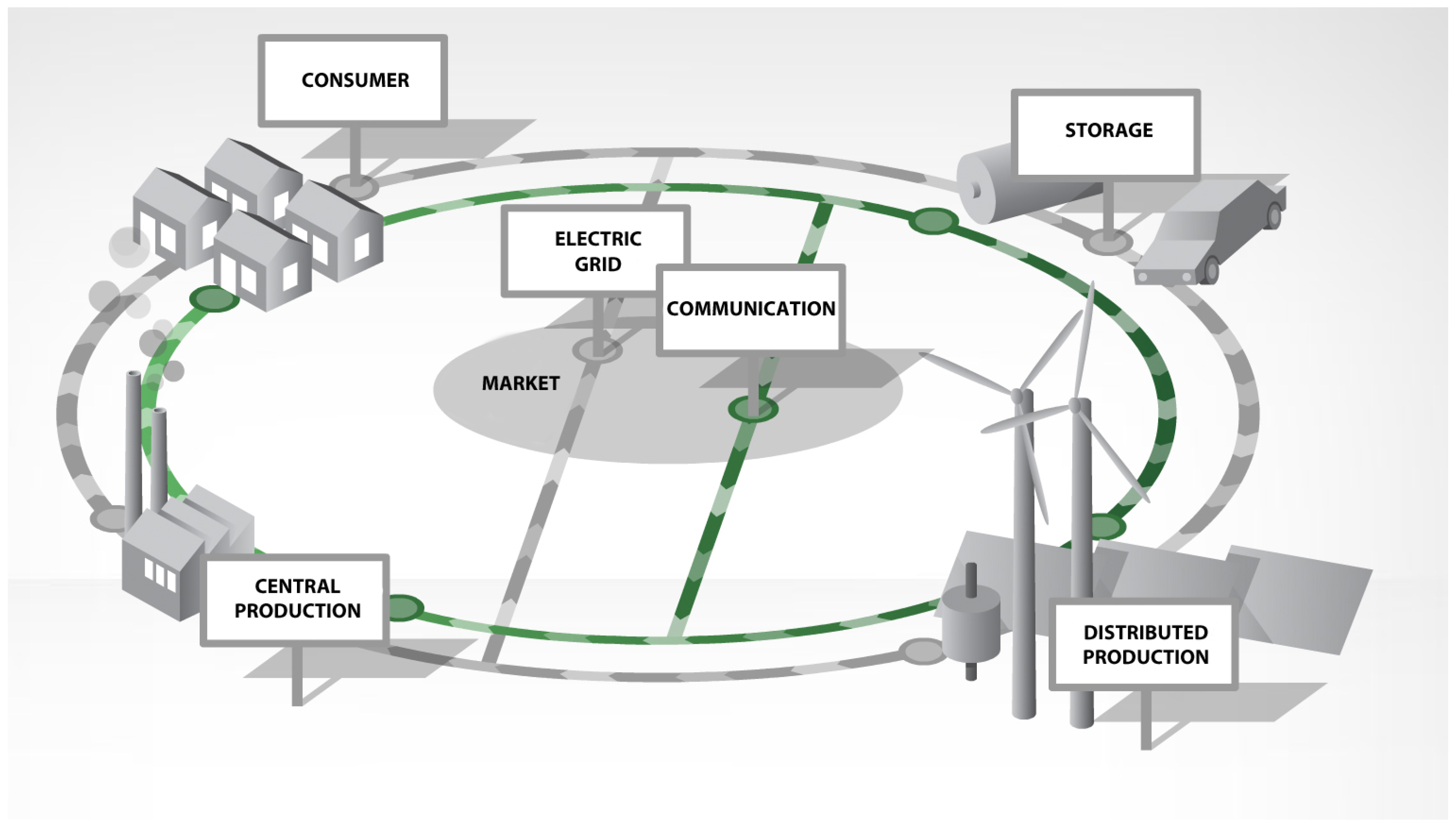
The energy transition refers to the migration toward solely renewable energy sources (RES) feeding the power grid. Their diverse size, their fluctuating production potential, their total number and their intrinsic heterogeneity makes it somewhat difficult to meet legacy grid requirements and challenges the reliable grid control. Solar energy drives all renewable sources. The sun enables the growth of plants, propels the weather system and thereby the wind and the water cycle, which in addition to photo-voltaic panels and mirror based systems are utilised to generate green secondary energy by wind turbines, hydroelectric power plants, and bio-gases. However, these primary sources are fluctuating, they are not available in the same amount at all times [1]. In Figure 1, an overview of the central participants of a Smart Grid are shown.
Figure 1 also sketches the communication demand among the participants required to safely operate the grid. For safe operation, it is necessary to constantly balance the power grid by assuring that at any time the energy production meets the consumption. To better integrate small and less control-able distributed energy resources (DER), these assets can be yoked into Virtual Power Plants (VPP). A VPP commonly combines many different DER to constitute a virtual plant that can communicate as one entity with energy markets and grid operators, the latter being local Distribution System Operators (DSOs) and possibly transnational Transfer System Operators (TSOs) [2,3,4]. The aggregation reduces the communication interfaces to external partners and enables more flexible energy production and consumption management in defined areas.
Internal as well as external communication interfaces, data models and operation protocols need to be sensibly specified to allow the integration of DER from different vendors. Thus, interoperability [5,6] is a key factor to successfully integrate distributed RES and smart DER in the energy distribution and grid control, which constantly improved over many decades. Integrating novel energy sources and services is, therefore, a big challenge. The individual components of any smart energy system rely on seamless cooperation, i.e., on exchanged information used to reliably support the operation of physically connected system of systems (SoS) being the power grid.
The deployment of a Smart Grid is possible when vendors and customers work together to establish joint solutions, where smart energy systems’ interaction is feasible. Organisations like the IEC and VHPready recognised that and develop basic application profiles utilising joint consortia consisting of different vendors (cf. Section 2.6 and Section 2.7). The Austrian Project Integrating the Energy Systems (IES) [7] adapted the IHE methodology from the healthcare sector to match the energy domain by specifying exemplary use case centric interfaces for energy systems and by establishing an interoperability testing framework, the annual Connectathon Energy. The main goal of IES is to provide a workflow for the energy domain that fosters interoperable energy system components required for the communication in Smart Grids. The core contributions of the work performed are:
- Transferring the IHE methodology into the energy domain,
- Providing a test environment to specify and document test cases and test sequences,
- Validation of the IES methodology via exemplary profiles for VPPs based on IEC 61850.
The IES workflow and the results from the Connectathon Energy presented in the following are an extension of the conference poster abstract [8]. The proposed workflow is explained in more detail, from profiling to testing. In the following Section 2, the considered methodologies and some other works in the field of interoperability are outlined. The IES workflow is introduced in Section 3 and Section 4 and Section 5 describe the major steps. The validation of the IES workflow is presented and discussed in Section 6. Section 7 concludes the paper providing an outlook on further envisaged and progressing steps toward a general application of the methodology.
2. Related Work
The concept and methods applied by the project Integrating the Energy System are based on recent research results and recommendations on achieving interoperable IT solutions and the Single Digital Market envisaged by the European Commission [9]. These are briefly outlined in the following subsections.
2.1. The IEC 62559 Use Case Methodology
The IEC has standardised the Use Case Methodology from the European mandate M/490 in the series IEC 62559 [10]. The methodology describes complex systems functionalities, actors and processes in a structured way. The methodology is used to analyse requirements and to detect standardisation gaps; e.g., in data models and protocols. Use Cases are first building blocks in software engineering to specify systems. The system functionality is approached from a static and a dynamic point of view: involved actors and system boundaries are considered static and relations between the actors contributing to a Use Case show dynamic aspects [1,11].
With the IEC 62559 Use Case Methodology, use cases are textually described in a template by application and implementation experts. The template is specified in IEC 62559-2. The other three parts of the standard series classify the operational use of the methodology, possible tool-support, and best practices. For the template, an XSD schema is defined to enable content exchange between different tools [10]. The template contains the eight parts shown in Table 1. The first two parts can be defined by domain experts: it provides the management perspective. The technical requirements are specified by application and implementation experts in parts three to six. The last two parts are jointly completed where necessary. Based on the structured Use Case description, technical specifications can be derived; i.e., architecture models (cf. Section 2.2) and interface specifications (cf. Section 4.2).
2.2. The Smart Grid Architecture Model (SGAM)
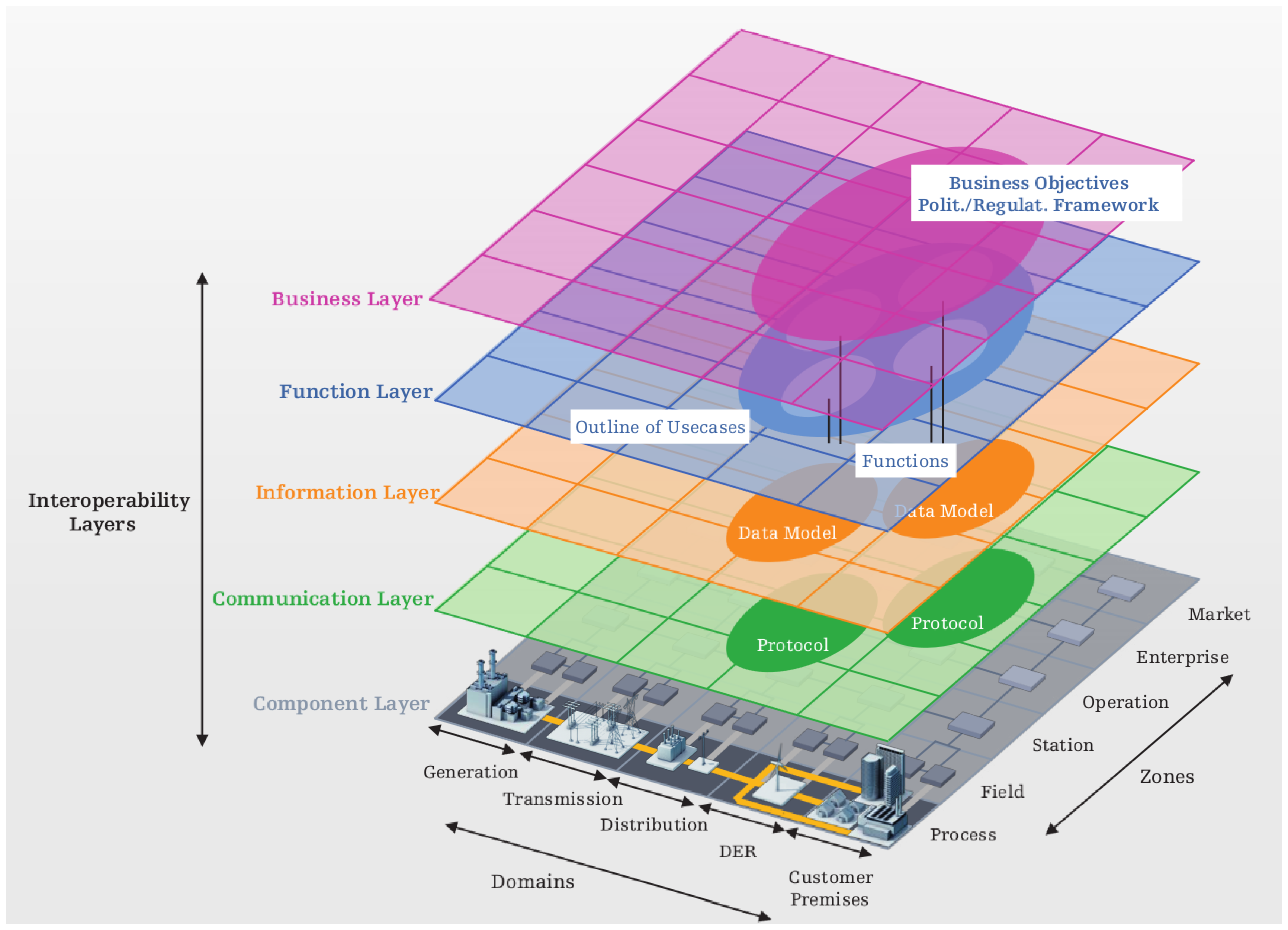
For visualising connections within Use Cases, the Smart Grid Architecture Model (SGAM) can be applied. The SGAM resulted from the European Mandate M/490, where the GridWise Architecture Council (GWAC) stack became adopted for the Smart Grid domain [12,13]. The SGAM is a three-dimensional visualisation, presented in Figure 2, that helps to identify components and their relations. An example application is later shown in Section 4.1.
From the top to the bottom, five layers are used to consider different interoperability aspects (viewpoints). It starts with the Business Layer, where regulatory and economic structures, business models and processes are positioned. On the next layer, the functional view, the functionalities are located. The required functionalities result from analysing different Use Cases. On the Information Layer, the used and exchanged information is considered; i.e., the Use Case specific semantic for functions and services to enable an interoperable information exchange. Therefore, information objects and canonical data models are positioned here. On the Communication Layer, protocols and mechanisms for the information exchange between actors are positioned; i.e., the data channel specification. The Component Layer is the lowest level and covers the individual entities that contribute to the Smart Grid. It includes autonomous systems, connected components, atomic applications, and any kind of smart devices. Each layer spans all domains along the energy conversion chain, from generation to consumption, as well as the control and management zones, from process until market control and management, respectively [14].
The energy conversion chain starts with the generation of electric energy that is typically connected to the transmission system. The transmission is the infrastructure and organisation that distributes the electricity over long distances to major industry and cities. The distribution represents the infrastructure and organisation that distributes the electricity to customers within a specific region. Distributed Energy Resources (DER) are comparably small power plants feeding electricity into the distribution grid. At the end of the chain, customer premises refers to the industrial, commercial, and residential facilities of energy consumers. The aggregation, separationand utilisation of the information used to manage the power system is governed by organisational and legal rules on participating in the energy sector. In the market zone, possible market operations along the energy conversion chain are considered; e.g., energy and capacity trading. The enterprise zone covers commercial and organisational processes and services; e.g., customer contracting and billing. The operational zone refers to power system control operations for the generation, the transmission and the distribution systems. The station zone aggregates data and functions from the field zone, which describes the equipment to protect, control, and monitor physical processes and power flows. In the process zone, physical, chemical, and spatial transformation of energy, the applied physical/mechanical/electrical equipment, is represented [14].
2.3. The Open Group Architecture Framework (TOGAF)
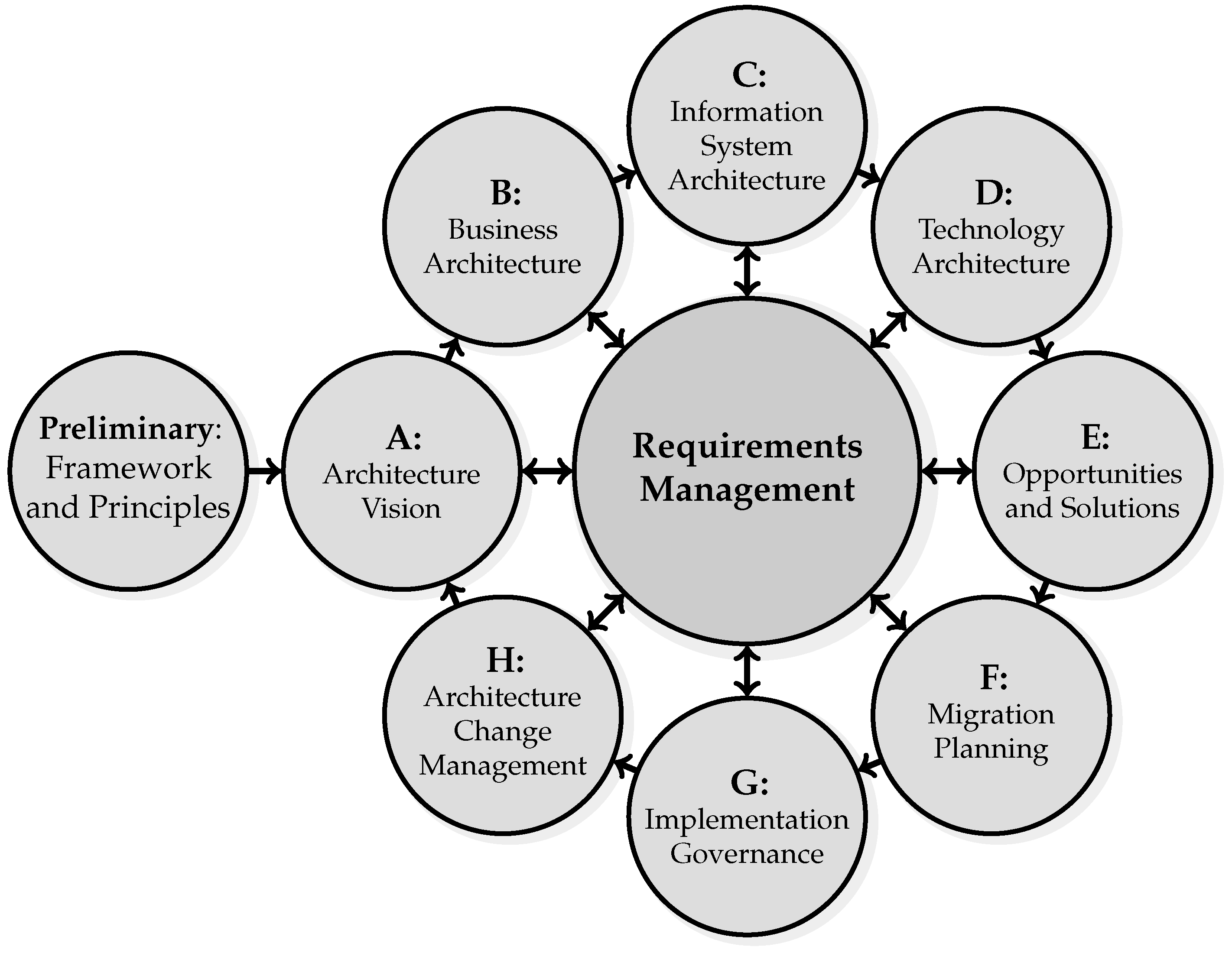
The concept considering different viewpoints on an architecture is also used by The Open Group in their Architecture Framework (TOGAF) [15]. This logical cyclic process for developing an architecture is depicted in Figure 3. It is a widespread and mature enterprise architecture development framework that covers three high-level viewpoints; i.e., business, information system and technology architecture [1,15]. The business architecture addresses management and planning; e.g., business strategies, governance, and organisation. The information system architecture can be divided into data and application centric views. The former supports database designers, administrators and systems engineers to structure an organisation’s logic, its data assets and resources. The latter addresses system and software engineers describing the logic of the system; i.e., the business processes. The technology architecture describes the hardware and software capabilities to implement business needs; i.e., data and application services [1].
The cyclic TOGAF process consists of eight steps plus a preliminary step and a central constantly used, as shown in Figure 3. A possible application of the steps is described in Section 4 and Section 4.2. In brief: A preliminary phase takes place to identify enterprise-specific frameworks or principles before the architecture development starts. The first step in the actual architecture development is the architecture vision. It is about the definition of the envisioned architecture scope and analysis of stakeholders and their needs. Defined objectives are the basis for architecture viewpoints. Following the first step, the business, the information systems, and the technology architectures are developed. Base thereon the initial implementation is planned in opportunities and solutions. During migration planning, an implementation and migration plan is developed, which include the definition of working packages and building blocks. Implementation governance addresses the supervision of the implementation; e.g., check whether the implementation meets the objectives. The TOGAF process ends with the step architecture change management, where based on monitoring and verifying the reactions a subsequent iteration of the process may be triggered. The requirements management action is connected to every step because it covers the requirement monitoring necessary in parallel to each step.
2.4. Integrating the Healthcare Enterprise (IHE)
Formed by healthcare professionals and industrial partners the IHE initiative aims to empower secure and coherent transfer of information between involved computer systems. The ability of a system to communicate with other products or systems, whose interfaces are completely understood, without any restrictions, is a basic concept of interoperability. The IHE initiative defines interoperability profiles based on existing standards (e.g., DICOM, HL7), creating a framework for interoperability testing definitions. Each profile contains the definition of involved actors, transactions and their mutual relationship in terms of information transfer. The experts supervised interoperability testing events, called Connectathons, take place annually [16,17]. The IHE process consists of four steps:
- Critical aspects of information transfers are identified and thereby relevant Use Cases defined.
- IHE profiles are jointly developed to detail every communication via established standards.
- Vendors develop systems that implement the communication as specified in IHE profiles.
- The interoperability of a vendor’s system is peer-to-peer tested at Connectathon events.
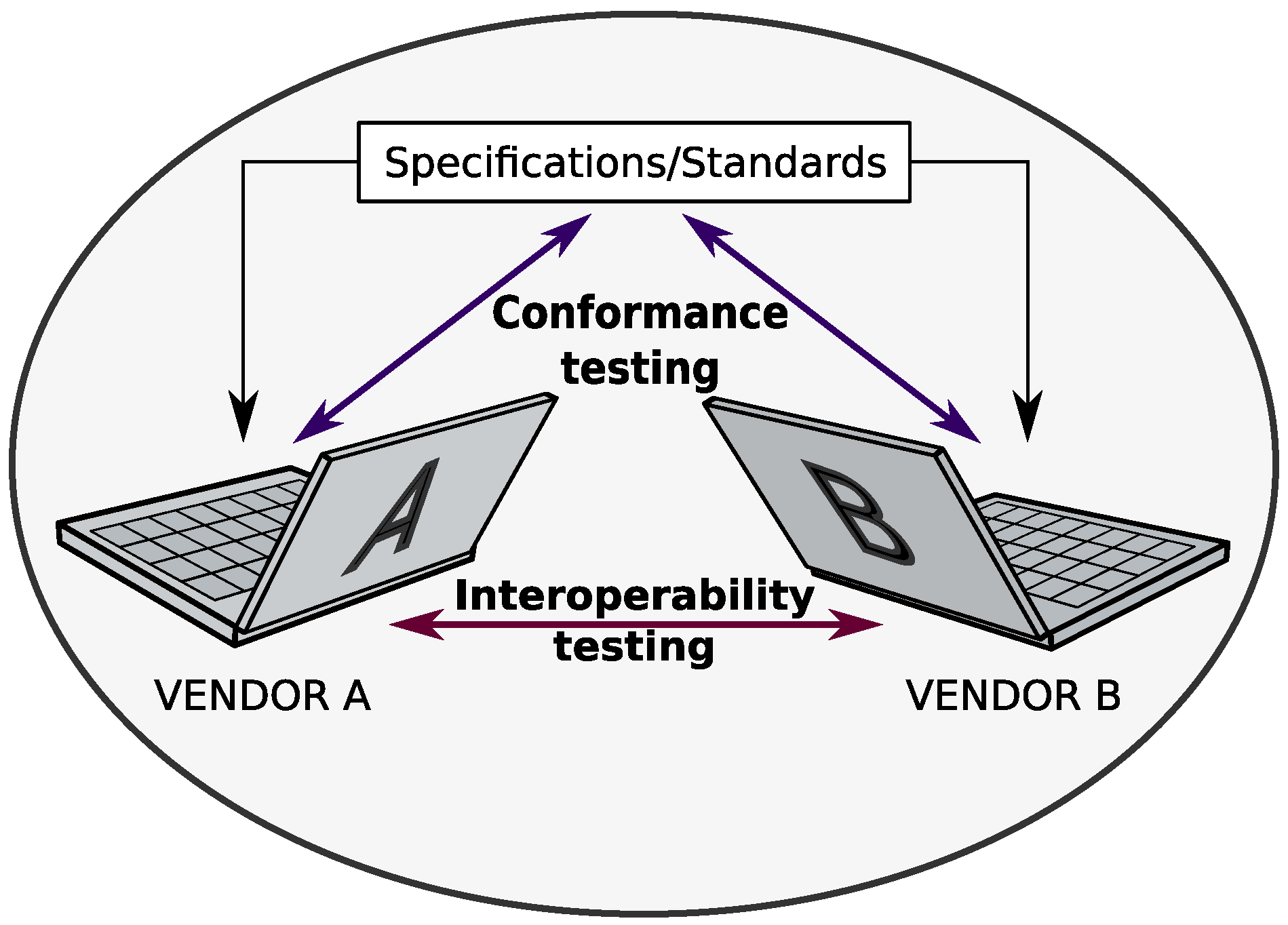
2.5. Gazelle—A Test Platform for Interoperability Testing
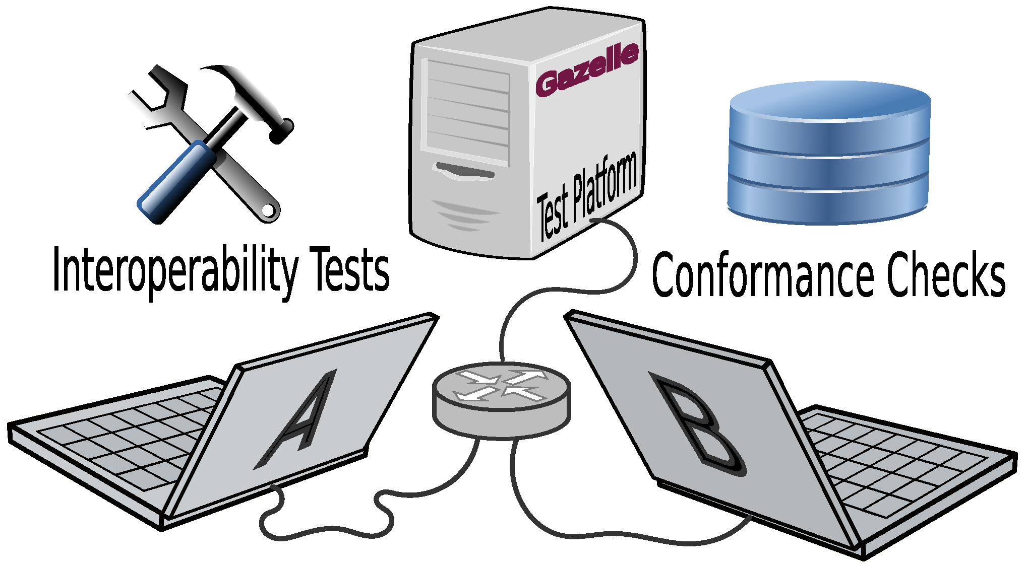
Gazelle is the name of the test bed used at the IHE Connectathons since 2006 [18]. It provides the means for mainly two flavours of software testing: (1) interoperability testing and (2) conformance testing [19] as shown in Figure 4. Meanwhile, the list of features supported by Gazelle has risen. From the test organisation perspective, this tool is used to register the companies, the systems under test (SUT), and their implementer. On the other hand, it provides Gazelle with the Integration Profiles that can be tested (including relevant actors and transactions) and the related test case definitions.
To capture exchanged data, Gazelle provides a proxy that is configured to log all messages exchanged between SUTs participating in a test case. The logged messages (traces) can be validated for syntactic and semantic compliance in a subsequent step using the validation services available in Gazelle or from external sources. The Gazelle Transformation Service facilitates binary to XML transformation by means of DFDL (Data Format Description Language) schemata.
Finally, the Gazelle platform documents the result of every conducted test step and hosts the Connectathon results and a Products Registry for successfully tested products that achieved an Integration Statement.
2.6. IEC Basic Application Profiles
The Smart Grid Mandate M/490 developed a concept to achieve interoperability by using existing standards. The concept is named Basic Application Profiles (BAP) [20]. BAPs define elements in modular frameworks for specific Use Cases of energy systems—a standard set for an application. Contrary to common standards, the BAP specification contains only mandatory aspects that have to be implemented to realise the Use Case and enable interoperability [21]. Use Cases address business problems identified by vendors and customers who need a solution for as specific issue in a given environment. To solve it, every feature is divided into elementary parts, which can be recombined to define more complex Use Cases. A profile consists of a profile name, requirements, boundaries and scalability, standards and specifications, communication network topology, and best practices.
Each BAP can be used as building blocks that, in combination with others, realises complex applications (cf. Section 2.3 and Section 4.2.1 where the concept of building blocks is also used). An extension of BAPs are Basic Application Interoperability Profiles (BAIOP) [22] based on the V-Model [23]. BAPs provide an implementation strategy and BAIOPs contain an approach for testing on different levels (e.g., unit, integration, system, and acceptance testing) that also considers interoperability. Therefore, further specifications are defined with BAIOPs: device configuration, test configuration, test cases for the BAPs, specific capability descriptions and engineering frameworks for data modelling and communication infrastructures, which together enable the testing of a proposed system.
2.7. VHPready
VHPready e.V. [24] is an alliance, founded by stakeholders of the energy industry targeted to specify an industry-standard enabling interoperable communication in the field of virtual heat and power plants. The communication is based on IEC 60870-5-104 [25] or IEC 61850-7-420 [26]. Based on these standards and identified Use Cases, VHPready defines a set of data points that specify needed data objects either from IEC 61850 or 104. Based on the specified restrictions, VHPready compliant systems can be modelled and implemented. Moreover, the list of data points enables a mapping between the two different standards.
VHPready focuses on the interoperable communication between DER and a VPP operator (aggregator) and does not consider issues with other assets and entities of the energy system that may be needed to fulfil related Use Cases that reach beyond the boundaries of managing a VPP.
3. IES Workflow Overview
The project IES migrates and adopts the established and matured IHE methodology on achieving interoperable IT based healthcare systems. All started with incompatible digital X-ray images (radiology) in 1999 and by today covers many areas and achieved wide acceptance in the US, Europe, and East Asia. For example, the Austrian digital health record database [27] is entirely based on public IHE Integration Profiles. The generality and success of the methodology motivates the migration into the energy sector with similar security demands, market structure and regulatory governance.
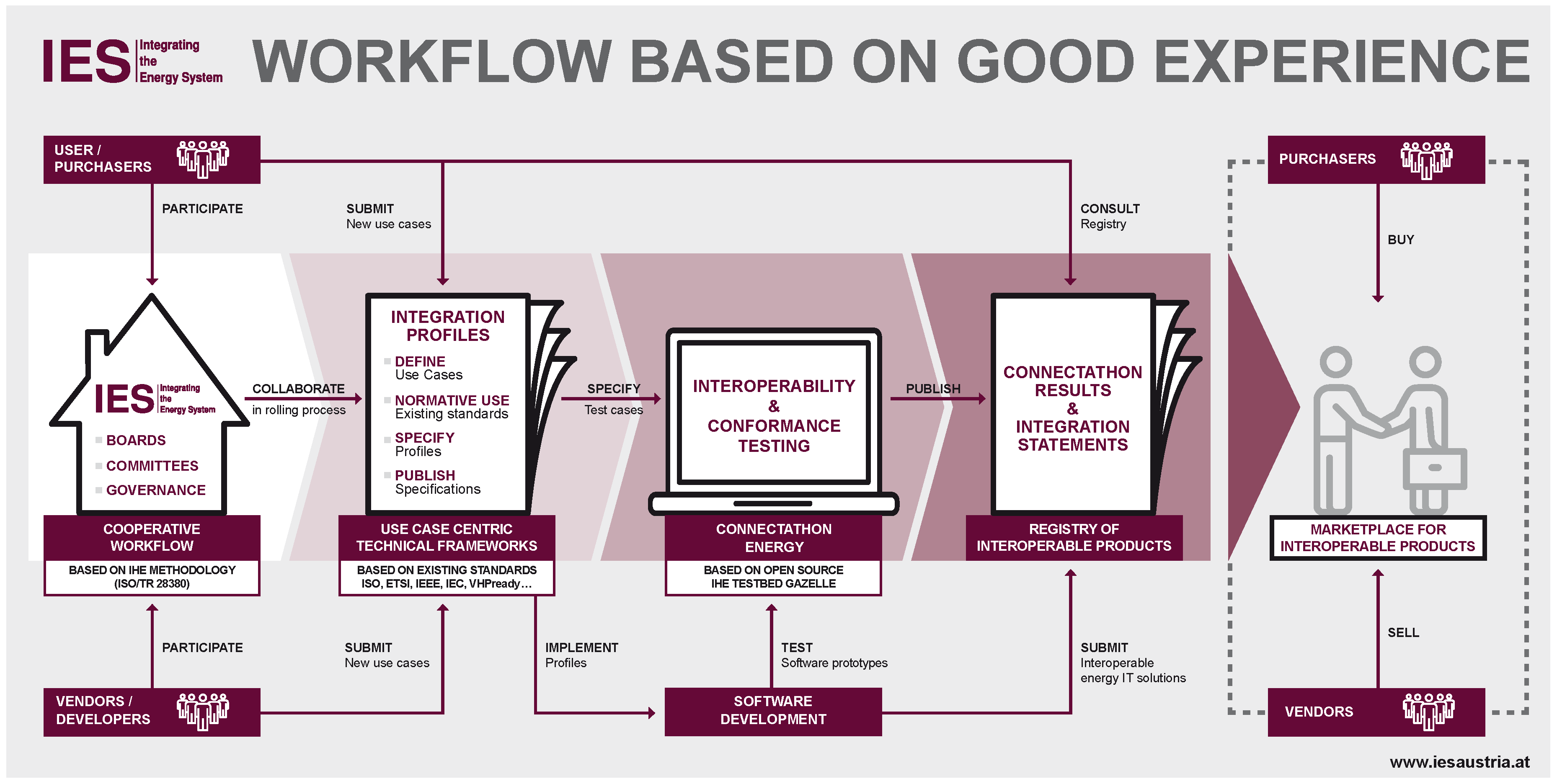
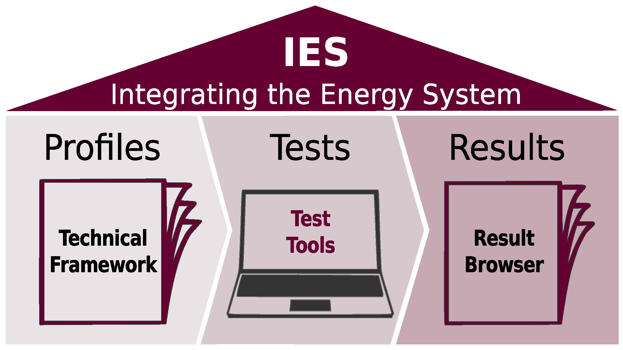
The IES methodology realises the four basic steps shown in Figure 5, which evidently split up into many more intermediate steps [28]. A moderate expansion yields:
- Identify Use Cases where interoperability is an issue and specify these by identifying system borders and requirements [11]:
- Write a Business Overview (define actors, the environment and the general issue),
- Describe Business Functions (apply the Use Case Methodology and draw UML use case diagrams),
- Reuse Integration Profiles where possible (save specification and test effort).
- Jointly identify how interoperability issues can be prevented and specify the requirements normatively as Integration Profile [19]:
- Evaluate which standards can be used to fulfil the Use Case requirements,
- Specify the process to realise a Business Function (UML sequence diagram),
- Define the actors and transactions (decompose Meta-Actors into modules),
- Describe the role of the individual actors (modules),
- Draw an Actors-Transactions Diagram (decompose the process into steps),
- Draw detailed UML sequence diagrams per transaction (steps sequence),
- Specify additional communication and security requirements.
- Test independent prototype solutions against each other on annual plugfest and improve the Integration Profiles until it is fixed [29]:
- Specify test cases and test sequences according to Integration Profile specification,
- Integrate test cases, procedures, and documentation in test environment (Gazelle),
- Create or integration conformity validation tools (e.g., Schematron),
- Develop simulators as dummy pre-Connectathon test partner (optional),
- Execute test cases with at least two independent peer vendors,
- Validate recorded messages/traces and log passed test results (neutral monitor),
- Publish successful test results: who has successfully tested which Integration Profile [29],
- Publish which vendors successfully tested an Integration Profile (Result Browser),
- Get written approval for successful implementation (Integration Statements).
Integration Profiles shall be living documents that improve and grow until they become stable. The core idea of the methodology is lively cooperation between the users and vendors. All stakeholders shall participate in the process as peers and contribute jointly to the development of demand oriented solutions. Sometimes, interoperability can be achieved most reliably with very simple means that work fine for many. In contrast to certification, where one system is tested against a set of rules or a single reference system, here the implementer from different vendors test their solutions among each other.
All peers participating in a test case have a common goal: they want to ultimately pass the test. A multi-day plugfest provides the environment and time to learn and make corrections prior to the final decisive test. Implementer can talk to each other and jointly identify why something does not work as it should. Such issues are often based on different interpretation of the Integration Profiles, which demands amendment of the text. Comments and errors recorded at the test event are the most valuable and powerful input to improve Integration Profiles. This feedback is practice driven and supports the advancement of the Integration Profiles in becoming a good basis for interoperable systems that can be integrated in the bigger system-of-systems.
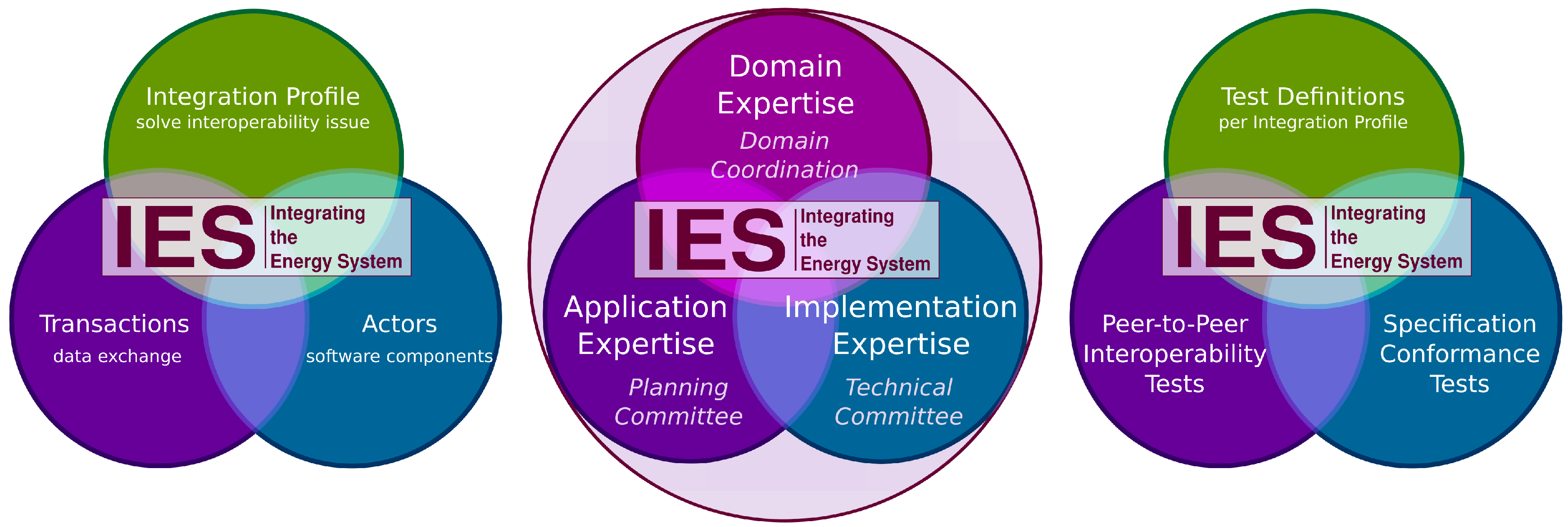
3.1. Process Coordination and Control
The committees of IHE are instruments that manage and implement the industry integration process. Their importance may be concealed by results, being the Integration Profiles produced and test events organised. However, it requires coordination and cooperation to achieve interoperability. It is important that a committee is addressable, so tasks can be forwarded to it and its decisions are accepted by all stakeholders. Committees fulfil required roles that demand certain skills, which are presented in this section. Different skills are fundamental to execute the various management tasks that coordinate and control the IES process. Committees, depicted in the centre of Figure 6 as connected circles stating the skills grouping foreseen, manage the topics related to profile preparation and test execution, shown on the left and right sides, respectively.
Functional roles are defined to manage the integration process by the committees. Experts can serve in one, two or all roles, depending solely on skills they actually contribute. Participants in committees shall be voluntary delegates from institutions, companies, and enterprises interested in interoperable solutions.
The planning committee and the technical committees are the main working bodies. The planning committee assigns Integration Profiles to Technical Frameworks and is responsible for organising testing events, including the decision whether profiles are ready for testing either as trial or mature Integration Profile. The technical committees are the task forces writing Integration Profiles and specifying test scenarios, i.e., test cases and sequences, and providing tools like the test platform Gazelle (cf. Section 2.5) and its components (proxy, simulators, evaluators, as well as the logging, reporting and documenting means and repository), essential to reliably execute test cases. In addition, the domain coordination board, composed of experts covering all domains, is in between and resides slightly above. It determines which domain a Technical Framework shall be assigned to. Moreover, it supports technical committees by proposing cross-domain reuse of existing Integration Profiles to prevent the development of redundant Integration Profiles. Thereby, the technical solutions landscape is also harmonised across frameworks, simplifying interoperability beyond domain borders.
3.2. Participation Benefits—Implicit and Explicit
The benefits of vendors and customers in contributing to the Integration Profile development is manifold. First of all, the contributing parties can influence the solution design. Thereby, customers can be sure that profiles match their needs. Both customers and vendors, gain an advantage from knowing early what will be specified when new profiles become released—not least, gain vendors and customers trust and respect from working together toward a solution that satisfies both sides.
The publicly available Integration Profiles speed up the development of products because they provide clear answers to questions on possible options. Profile conformity allows start-ups and small companies to offer sub-systems that can be integrated into big systems without the need to develop dedicated interfaces to potentially proprietary systems on the market. Market leaders need only one extra interface to make their solution interoperable.
Testing prototypes at a Connectathon Energy has two main benefits: firstly, vendors profit from testing their prototypes with peers. In the course of the test event, they can identify and possibly even solve problems in an early development stage, with the active help of their peers who also want to solve their issues and pass the tests eventually. Secondly, companies that successfully pass the test cases of an Integration Profile become publicly listed after the event in the public accessible Result Browser. On demand, vendors can get Integration Statements. These list the Integration Profile related test cases that a system (product and version) has successfully passed. Such a statement is essential if a tender requests the successful testing of certain profiles. The latter is a clear advantage for customers because it enables them to precisely specify what they want without going deep into technical details.
Finally, if wished by the vendor, Integration Statements can be added to the publicly accessible Products Registry. Being listed is of particular importance for start-ups and companies that launch new products they might not be known for. The registry is a neutral, still valuable, marketing and advertisement forum. System purchasers can find matching components by comparing the passed tests listed in the Integration Statements.
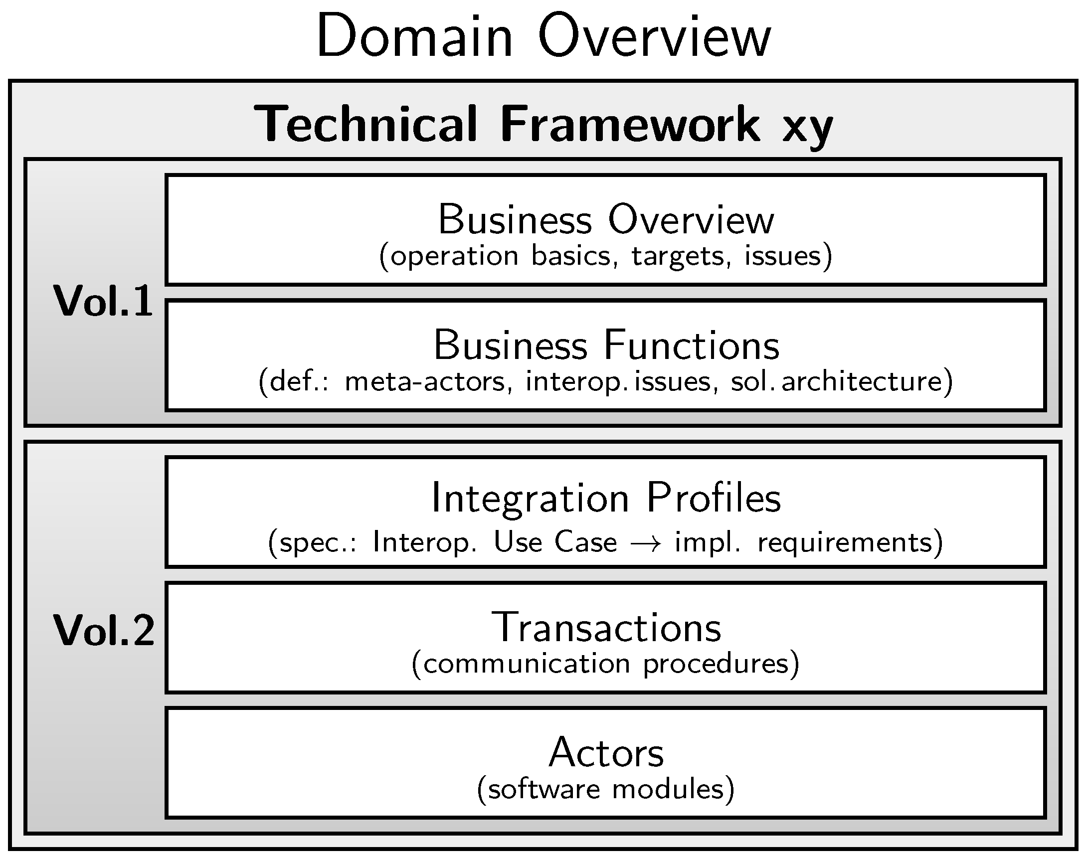
4. Technical Frameworks
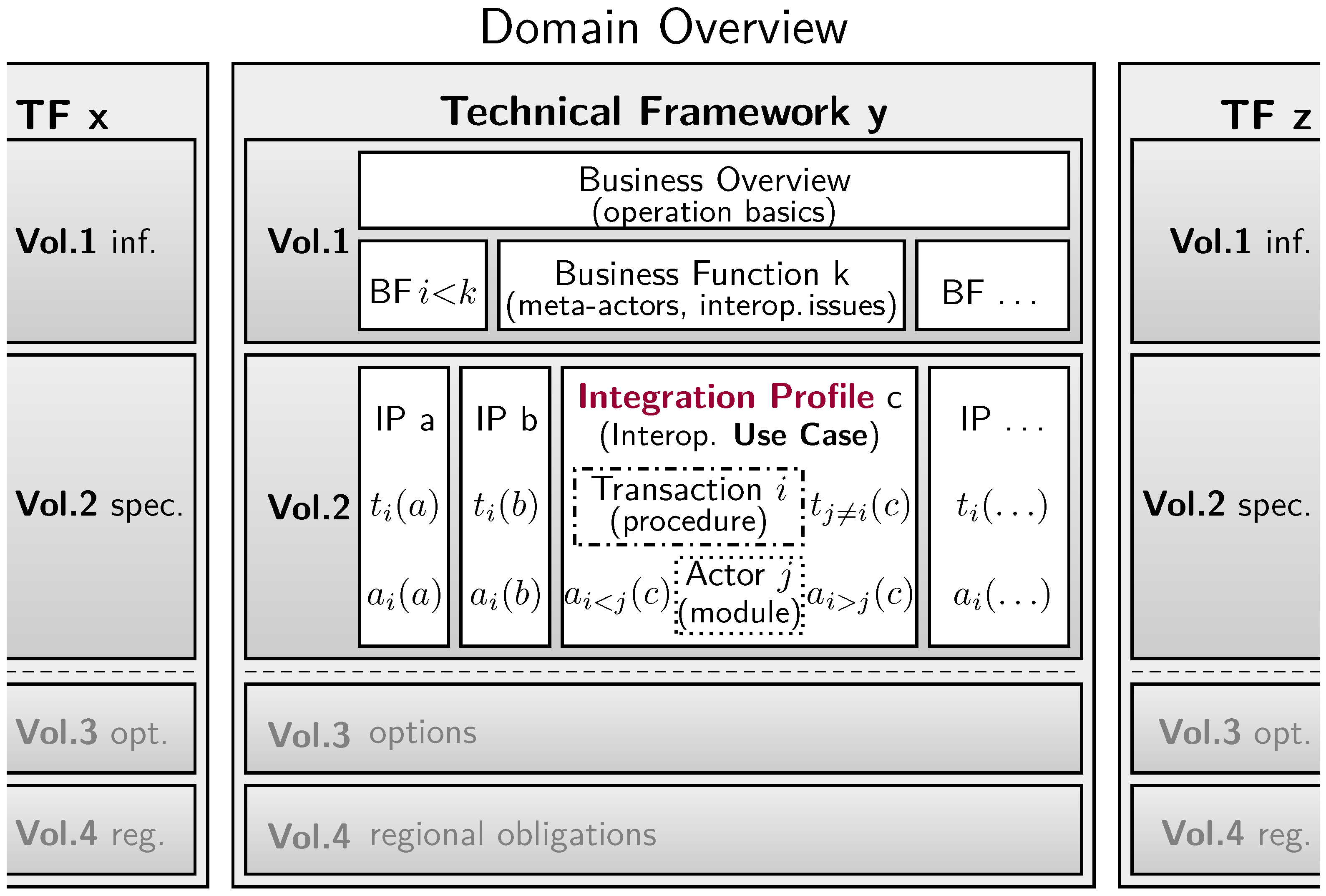
A Technical Framework (TF) is dedicated to a Business Case, e.g., the operation of a Virtual Power Plant (VPP), that belongs to a Business Domain—here the electrical energy production, distribution, regulation, and market area. The structure of a TF shown in Figure 7 is predefined, basically following a top-down approach in accordance with the IEC 62559 Use Case Methodology [10], the SGAM [14], the IHE Global Standards [30], and the V-model [23]. The relation to the architecture development framework TOGAF (The Open Group Architecture Framework) [15] and the European Interoperability Reference Architecture (EIRA) [31] is addressed later on. Figure 7 also shows that a Technical Framework is divided into two parts: a solely informative use cases (Business Functions) identification (volume 1) and a more normative solutions specification (volume 2).
4.1. Volume One—Informative
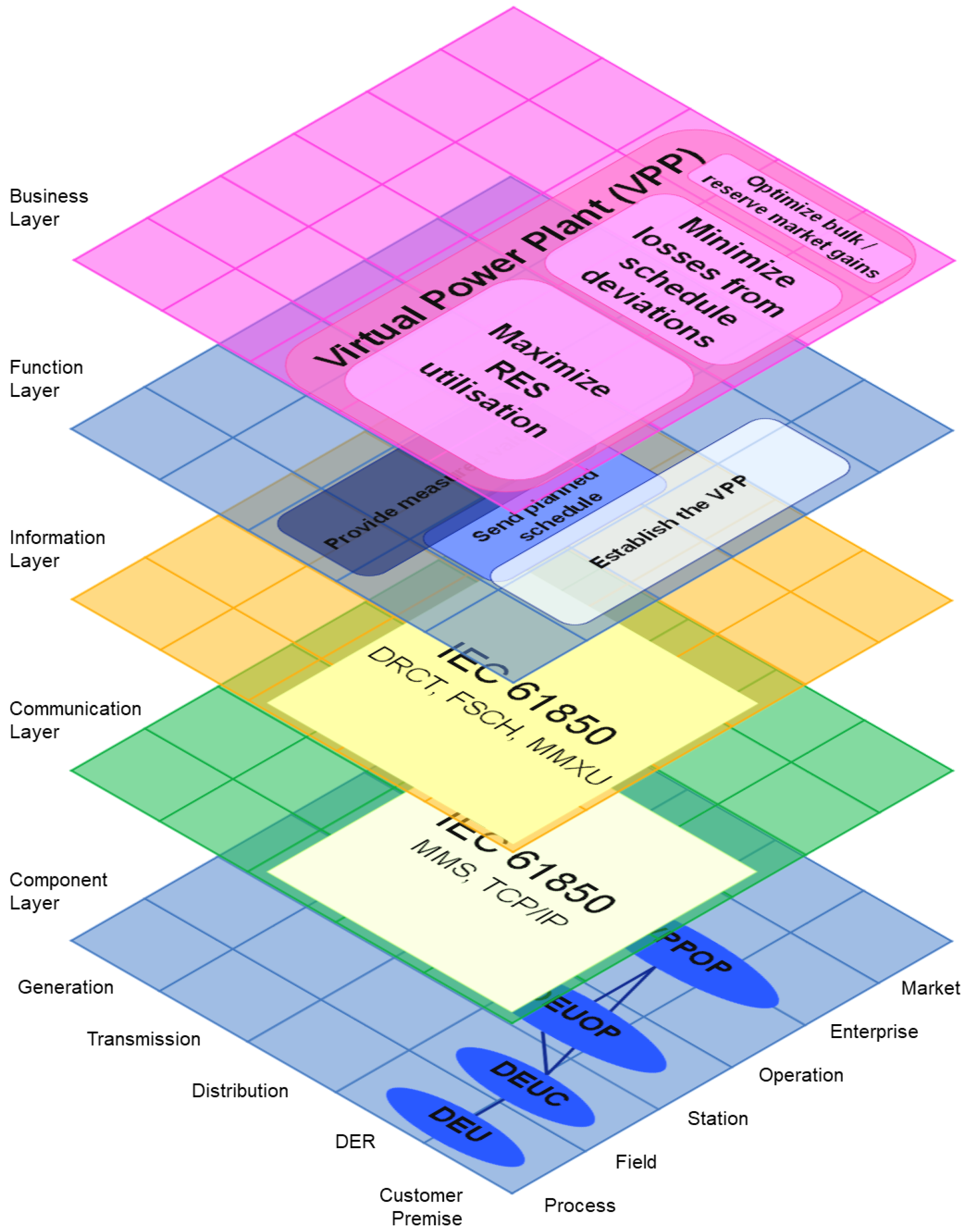
A Technical Framework starts with the Business Overview detailing the system environment, possible variants, and functional requirements. For the TF on VPPs, this includes at least the basic architecture, possible archetypes, and operational objectives. These are required to enable the specification of functional requirements. The application centric view corresponds with the Business Layer of the SGAM [14], shown in Figure 2, and step B in TOGAF [15], shown in Figure 3. The three-dimensional SGAM view (cf. Section 2.2) positions a VPP in the Distribution, DER, and Customer Premises realm and shows that the VPP operation covers all layers from Process till Market.
The next level of detail (one step down in the TF structure) identifies the functionalities required to establish a Business Case, which are called Business Functions in accordance with their implementation in the Function Layer of the SGAM. For a remote controlled VPP, functions like establish the VPP, send planned schedules, provide measurement values are specified. The identified Business Functions are documented applying the IEC 62559 Use Case Methodology (cf. Section 2.1). Information exchange sequences between actors comprise of steps from two categories: those that a business actor (meta-actor) performs on its own, and those where more than one actor is involved. The former, called Operational Use Cases, do not raise interoperability issues. The latter, called Interoperability Use Cases, are essential for interoperability because, for their realisation, more than one actor is needed. To prevent interoperability issues, these latter interactions need to be specified as Integration Profiles (cf. Section 4.2).
An excerpt of the Use Case specification that describes the Business Function send planned schedule from the VPP operator to some DEU controller is shown in Figure 8. It consists of the Use Case identification, the Narrative Use Case description and the Steps—Scenarios table as specified in the IEC 62559 Use Case template.
The Use Case identification provides a unique label (ID) according to a jointly agreed methodology. Next, it points out the placement of the Use Case in the SGAM area domains and zones (cf. Section 2.2). Finally, a human readable descriptive name of the Use Case is defined. The narrative Use Case description is composed as a short still complete textual description, providing a brief explanation of the Use Case. The complete description is a comprehensive user viewpoint centric narrative on what happens how, where, when, why, and under which assumptions. The narrative shall be written in terms and a language well understood by non-experts. The Steps—Scenarios table details the scenarios of Use Cases. The scenario name in the headline shall be the same as in the Overview of scenarios section of the template. The steps of a scenario are listed in consecutive execution order. Every step is identified by a step number and specifies the triggering event that causes the execution of the step. A triggering event is often an activity that also gets a unique name and may contains a short explanation of the procedure taking place, in addition to the name and description of the step it triggers. The service column states the nature of the information flow, e.g., get, create, or change, and the columns to the right specify the source, the destination, the information object exchanged, and additional requirements to be met.
The Use Case mapping into the SGAM is shown in Figure 9. The affiliation of the Use Case Send Planned Schedule to the VPP Business Case, the used data models and communication standards, and the involved actors are identified at a glance.
The result of these first two steps in preparing a TF, writing a Business Overview and identifying the required Business Functions, shall be summarised in a use case diagram. In this visualisation the involved actors (i.e., Meta-Actors that provide the sum of all features required to perform their tasks) get connected by the Business Functions they contribute to. This representation is the basis for the detailed Actors–Transactions Diagram, which shows only the interoperability relevant data exchanges between the actors (software components) the Meta-Actors are composed of. The detailed Actors-Transactions Diagram provides the schematic overview of the Meta-Actors composition at the beginning of Volume Two, summarising the technical functionalities to be specified by the Transactions of different Integration Profiles.
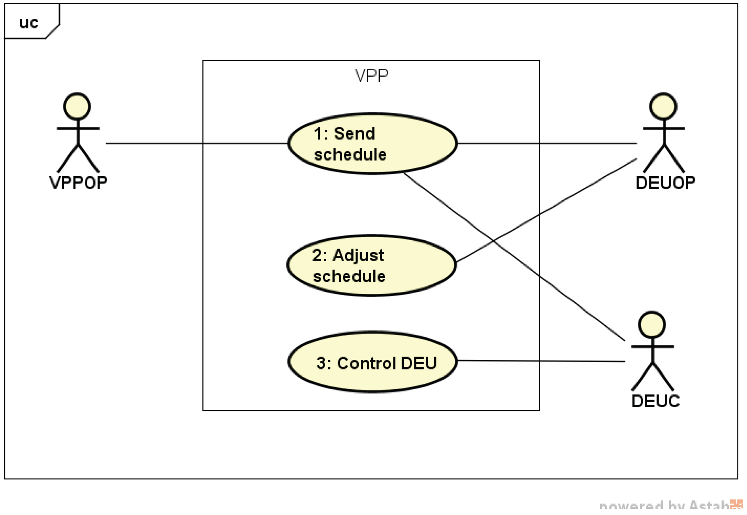
The TF–VPP example of a Use Case Diagram on requesting electricity production, i.e., Send Planned Schedule, is shown in Figure 10. Managing the information object functional schedule (FSCH) specified in IEC 61850 comprises three functions: (a) transferring the requested (intended) schedule from the operator to the production asset; (b) controlling the power generation according to the received (current) schedule; and (c) potential schedule adjustment in between reception and execution, as partially contained also in the template excerpt shown in Figure 8. Only the Send schedule function involves more than one actor (cf. Figure 10). Therefore, only this may cause interoperability issues. Interoperability among the involved actors is essential to correctly realise the transfer of the information contained in an FSCH object. The other two functions do not constitute interoperability issues and need not be specified by Integration Profiles and Transactions. Their correct implementation can be left open to the vendor.
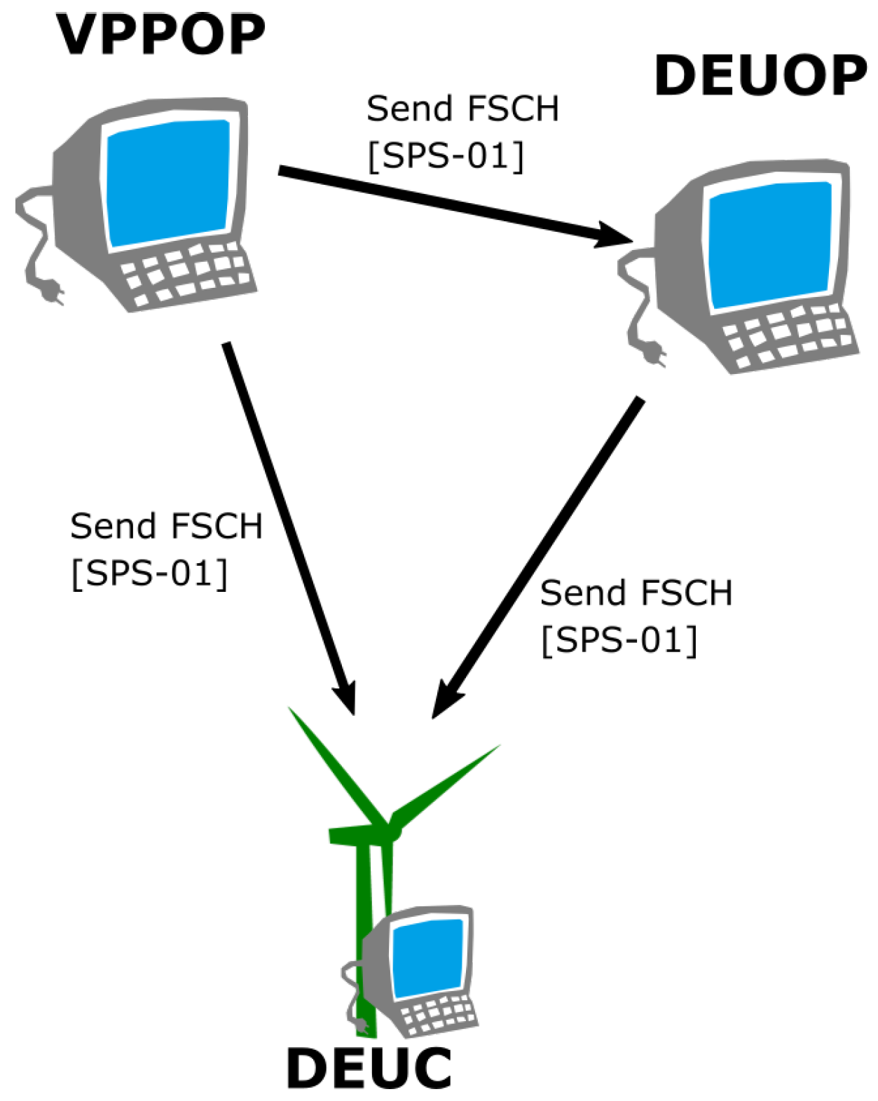
For the Interoperability Use Case lSend schedule, an Actors-Transactions Diagram is created, shown in Figure 11. It depicts the schematic view of the interoperability issue to be solved for the Business Function Send Planned Schedule. The diagram depicts the interdependence of actors; i.e., the interoperability demand of actors, and thereby the Interoperability Use Cases to be normatively specified in Volume Two. In the example, a VPPOP (Virtual Power Plant Operator), a DEUOP (Distributed Energy Unit Operator) and a DEUC (Distributed Energy Unit Controller) are required to realise the Business Function Send Planned Schedule that achieves the essential exchange of the information object FSCH, required to manage the power production of remote assets (here DER).
The Actors–Transactions Diagrams (cf. Figure 11) establishes the connection to the technical specifications in Volume Two and concludes the purely informative description of Volume One. This first part is required to understand why and where interoperability is necessary, being readable to managers and users likewise. Experts confident in the matter may go directly for Volume Two and consult Volume One where questions arise only.
4.2. Volume Two—Normative
Volume Two of a Technical Framework specifies normatively how the Interoperability Use Cases, identified and defined in Volume One, shall be technically solved, optionally including informative implementation examples. The resultant normative parts, each covering a Business Function’s interoperability issues, are the Integration Profiles, which constitute the core of any TF. They are so called because they specify what is required to achieve the interoperability necessary to pass the system integration test from the V-model [23].
Multiple features, for example operational, technical and security requirements may be specified within one Integration Profile or separately. To enable the latter, Integration Profiles can be grouped (bundled) to realise the complete Business Function, i.e., all its Interoperability Use Cases, via grouped Integration Profiles. Whether or not to split features depends on the reusability of features for other Business Functions, i.e., if the addressed Interoperability Use Case can be solved in the same way for different Business Functions. For example, setting up a secure connection between two actors most likely occurs with many Business Functions and shall therefore be specified in a reusable fashion, as an individual Integration Profile that can be bundled with other Integration Profiles to compose the different actors (software modules) that all use the same method to set up a secure connection if not already established.
Therefore, one of the first normative specifications required to get a complete Integration Profile is a table that specifies which other Integration Profiles need to be bundled with the one specified. Formally, this can be expressed by
where a identifies an actor (or Meta-Actor) and P an Integration Profile. The generic bundling rule in Equation (1) states that the actor a from Integration Profile P shall be mandatory bundled with the actor from Integration Profile . If all actors of a profile shall include the same actor of some other profile, we can use * as wildcard, i.e., .
This mapping nomenclature may be used with Transactions t and Business Functions f as well, where, for the latter, we need to specify the Technical Framework F instead of an Integration Profile P. For example,
states that, for the Business Functions , all actors from Integration Profile P and the transaction from some other Integration Profile shall be grouped. To do so, the actors required for the transaction shall be specified in profile ,
where, in Equation (3), actors from other profiles may as well become included using the nomenclature exemplified in Equation (2). How this formal approach can be extended and formally used to automate the specification of composed Integration Profiles is presented in [32].
In general, the specification of an Integration Profile follows the TOGAF steps C, D, and E, going down the SGAM Model from the Information Layer through the Communication Layer down to the Component Layer, respectively.
- Specify semantics and syntax for the required Information pieces, i.e., how information shall be converted into data and vice versa, how information shall be handled (protection) and in which format data shall be exchanged among actors.
- Specify the transactions, i.e., the communication channel and protocol that shall be used to transport data chunks from one actor to the other.
- Specify the actors, i.e., features and characteristics of sender and receiver components (drivers) to be integrated with actors.
These steps, and the two from Volume One, are reflected in the document structure, where, in Figure 12, the multitude of Technical Frameworks, Building Blocks, Transactions, and Actors is indicated.
In each step, on each layer, every interoperability relevant aspect concerning applied standards and available options, is to be normatively specified. This is a balancing act between flexibility and dogmatism because the actual implementation shall be technology-neutral and remains a vendor decision.
Sometimes, for specific customer demands, deviations from the generic approach are required. For example, options provided by a standard that differ from those specified in Volume Two may be implemented on customer or vendor demand. Such options, which do not comply with the generic specifications in Volume Two, shall be specified in Volume Three. Similarly, deviations enforced by regional legislation are to be specified in Volume Four. These extra Volumes are solely provided to allow deviations without spoiling the generic definition. Evidently, they shall be kept to the absolute minimum truly required.
The next step in developing products is combining the individual functional actors specified with the Integration Profiles into the Meta-Actors that realise the Business Functions defined in Volume One (i.e., step F and G in TOGAF and system integration in the V-model). This may be environment and variant dependent, and is consequently not part of the Technical Framework. The same applies for the last step H in TOGAF (and also the first, being A), which is performed by the system planner that decides which features to buy and how to integrate them in the existing system architecture.
4.2.1. Relation to TOGAF and EIRA Architecture Building Blocks
The sequential separation into individual parts is typical for top-down approaches, as are the Use Case Methodology [10] or the TOGAF Architecture Development Method [15,31,33]. What we call Business Functions, or more precisely the individual features a Meta-Actors shall or may implement, are the Architecture Building Blocks (ABBs) in TOGAF/EIRA nomenclature. Their normative specification, the ABB_spec, is alike the IES Integration Profile. The Solution Building Blocks (SBBs) are the chosen standards, the exemplary specified transactions and the provided implementation examples, as shown in Figure 13.
Note that SBBs are always examples only. How a vendor achieves the fulfilment of an ABB_spec, which here implements the specifications stated in an IES Integration Profile, is not relevant for the interoperability. Only what is actually required for interoperability needs normative specification.
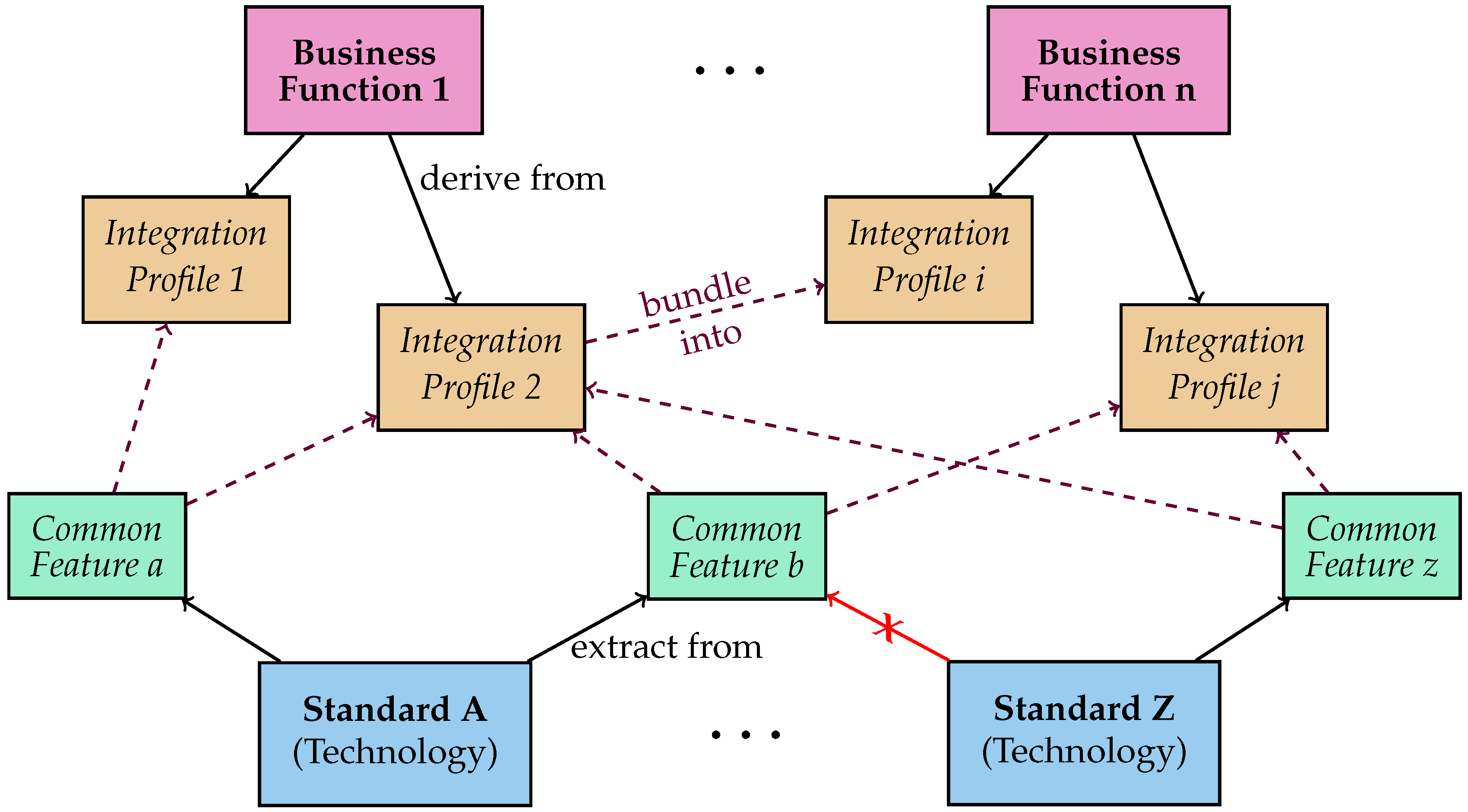
Having noticed that modern standards offer a plurality of options to realise certain features, all based on the same technical background but with many options, it appears straightforward to use the features that a standard offers as solution building blocks. These can than be bundled (grouped) with Integration Profiles, as shown in Figure 14. Their usage shall be constrained by the calling Integration Profile, such that interoperability is achieved precisely as required for the related Business Function.
These solution building blocks we call a Common Feature (CF). They represent best practice solutions or excerpts from standards. They may refer to a single standard only, and shall provide the full flexibility available. To specify a feature of a standard as individual CF is only economic if this CF is used by many Integration Profiles. However, if that is the case, CF saves redundant specification of similar usage of the same feature in multiple Integration Profiles.
CF may be used to specify parts of the conformance tests. The more restrictive interoperability tests, and the conformance to the Use Case specific, Business Function related, restrictions, obligations, and constraints, cannot be derived from CF because these are specified in the Integration Profiles only. Therefore, for the remaining discussion, we assume generally that tests are derived from Integration Profiles, presuming that requirements and specifications from bundled in profiles and CF are completely considered for every Integration Profile.
5. Testing the Interoperability and Profile Implementation Conformance
The IES approach on interoperability and Integration Profile conformance testing is the central pillar of the IES methodology, as shown in Figure 15. The Technical Framework, containing the Integration Profile definitions introduced in Section 4, specifies the requirements on how different assets (actors) exchange information to implement the functionality required to realise a Business Function, and thereby enable a business case. The well established IHE methodology underlines the essential importance of peer-to-peer testing to ensure interoperability between systems. Publicly available test results serve as proof of a system’s compliance with the specifications evaluated when passing a defined test case. When a software vendor passes all test cases defined for an Integration Profile, an Integration Statement can be requested. This document formally proves that the component it is issued for has successfully passed all defined tests to evaluate the implementation’s compliance with the listed specifications (Integration Profiles). The Integration Statement enables the vendor to promote its products, makes offers to tenders requesting compliance to listed profiles and convinces customers that the product can be integrated in an existing infrastructure.
Specifications may include uncertainty, such that vendors may implement specifications in divergent ways. To overcome this issue, peer-to-peer interoperability testing between independent developed systems is necessary. This kind of software test is most effective when a system from vendor A is tested directly against a system from an independent vendor B, as shown in Figure 16. To perform this, IHE hosts the Connectathon test events, which are an established and proven means to ensure the interoperability of systems beyond company boundaries [29].
The Connectathon test events are scheduled annually in Europe, the US and East Asia. The implementer of different vendors come together for a whole week and test whether information can be exchanged according to IHE Integration Profiles between their prototype implementations. These Connectathon events bring together the implementer for discussions and gives the community a forum for the validation of stated IHE specifications. Technically, IHE provides the test bed Gazelle [34]. This web-based tool provides, aside from event organisation functionalities, the features needed for test case management, system management, data traffic logging, message and sequence validation, and test documentation.
Gazelle’s validation uses primary XML validation methodologies, i.e., the validation services check the XML payload: if it is well-formed, whether the payload adheres to specifications specified in XML schema files, and if additional formatting rules are fulfilled, using XML-Schematron validation. Since the example VPP profiles specify the use of IEC 61850 compliant data objects exchanged using MMS to generate and transport data, here the payload is binary encoded. To validate the exchanged messages using Gazelle’s validation services, the binary encoded data need to be transferred into an XML representation. Therefore, the Data Format Description Language (DFDL) [35] and a Daffodil-Transformation [36] are used for the example. DFDL is an XML schema like a definition language extending classics schema file with additional information on how single bytes, and even bits, shall be interpreted in a form of annotations. Daffodil-Transformation is an open source tool that processes the binary data and generates XML files based on the specifications stated in a DFDL file. Gazelle already includes capabilities for this transformation step and, therefore, only the DFDL files need to be defined to create XML files from the logged messages containing binary encoded information. The resulting XML files can be further validated with the common Gazelle tools.
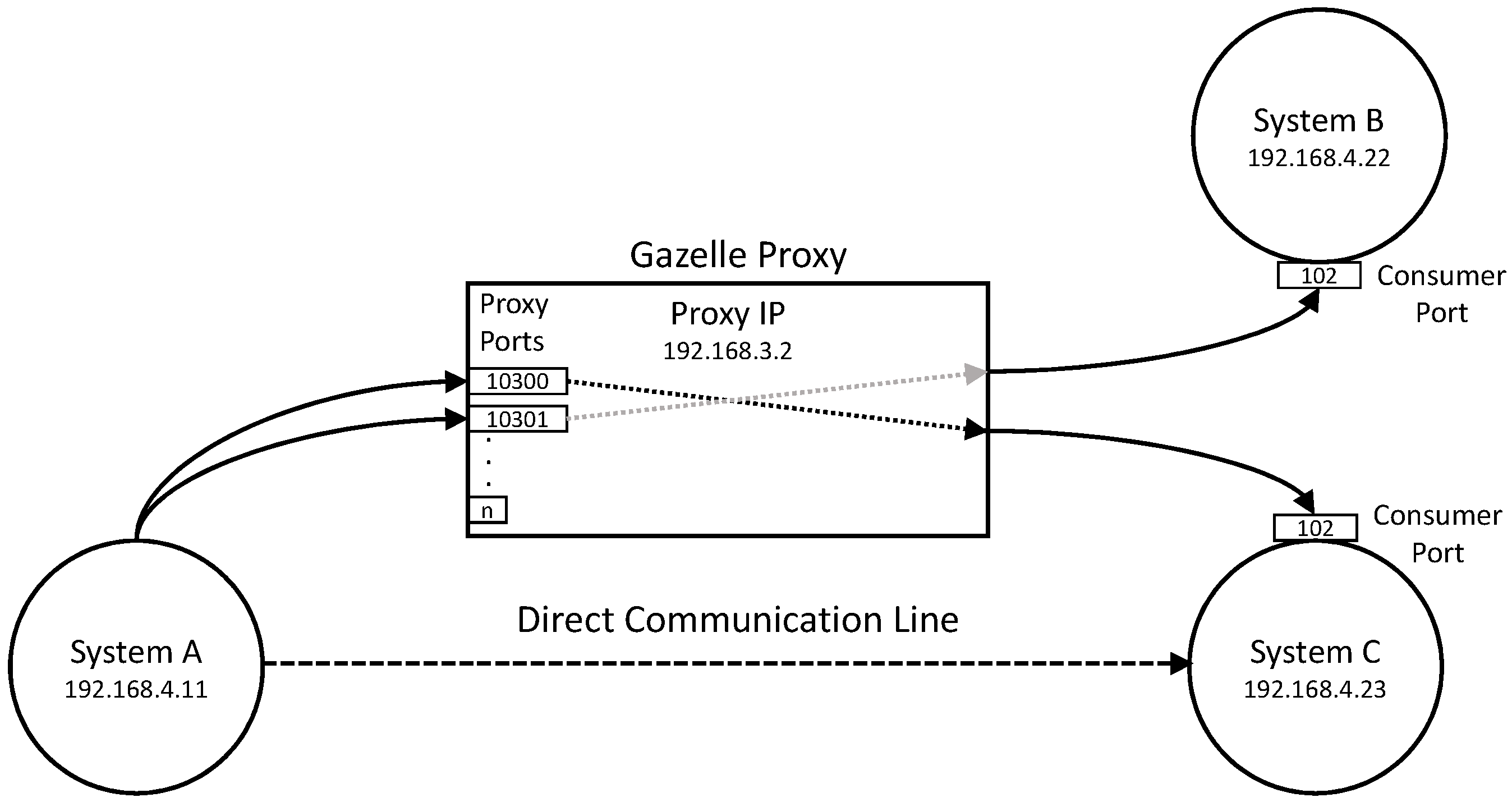
An essential features of the test-bed Gazelle is its capability to record messages that are exchanged between the systems under test (SUT). To use this feature called Proxy, the SUT needs to be configured not to communicate with test partners indirectly via the Proxy, as shown in Figure 17.
The proxy needs to be configured to assign all the corresponding endpoints to test instances and SUTs, such that messages received from a SUT are logged and in parallel forwarded to the correct receiving SUT. Logged messages can be forwarded to Gazelle’s validation tools (or external validation options). Only during this last step the Daffodil-Transformation stated above is applied to gain an XML representation of the message content for the actual validation.
6. Realisation of the IES Workflow
First trial peer-to-peer testing sessions have shown that interoperability between vendors is possible by using Integration Profiles demonstrated at the first IES Connectathon in conjunction with the IHE Connectathon 2018 in the Hague, Netherlands. Four different vendors have successfully implemented the following Transactions from trial Integration Profiles, and passed the according interoperability tests:
- Send MMXU: specifies how measured values are sent from a DEUC to DEUOP or VPPOP using the IEC 61850 logical node MMXU.
- Send FSCH: specifies how a functional schedule is sent from a DEUOP or VPPOP to a DEUC using the IEC 61850 logical node FSCH.
- Send DRCT: specifies how DER controller characteristics are transferred from a DEUC to a DEUOP or VPPOP according to IEC 61850.
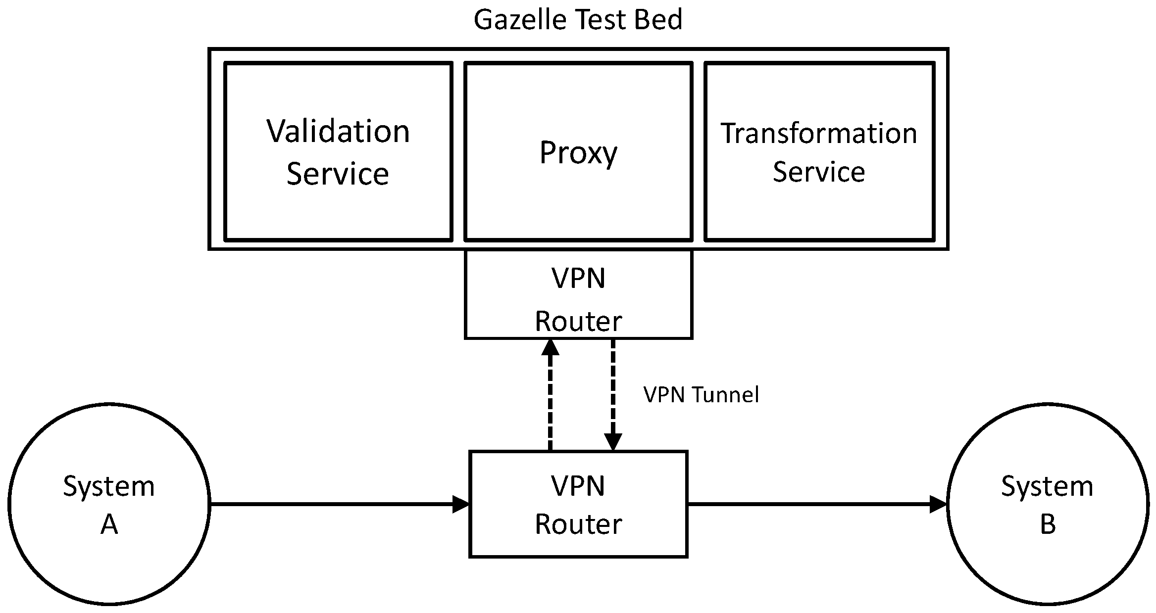
6.1. Test Setup for Interoperability Testing at the Connectathon 2018
Exchanged messages are recorded using the proxy of a dedicated Gazelle instance. The Gazelle instance is installed at the University of Applied Sciences Technikum Wien in Vienna, Austria. The local area network (LAN) used at the Connectathon floor for testing the energy components is managed by the IES team, independent from the IHE floor-LAN. The Gazelle instance running in Vienna is connected using a virtual private network (VPN) connection, as shown in Figure 18. This enables the recording and validation of exchanged messages via the Gazelle instance running on servers in Vienna. Gazelle management and configuration are performed via the Gazelle web interface.
6.2. Interoperability testing Result—Send Functional Schedule
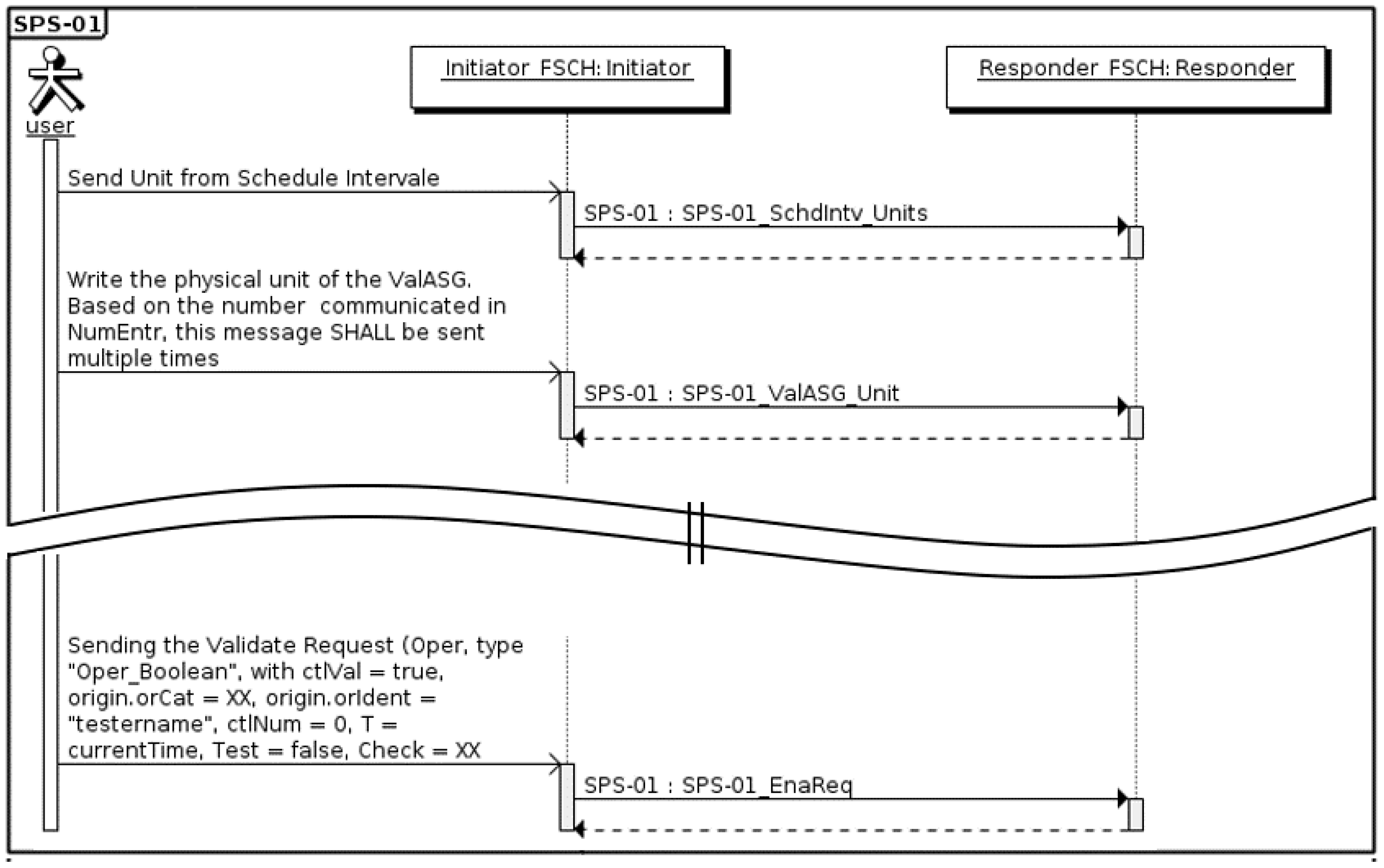
Test steps are defined for selective interoperability test scenarios. In general, the sequence diagram shows the required information exchange steps that need to be performed during a given testing instance. The transaction Send Functional Schedule (Send FSCH) is shown in Figure 19. The according test scenario evaluates the communication between VPPOP or DEUOP (System A) and DEUC (System B):
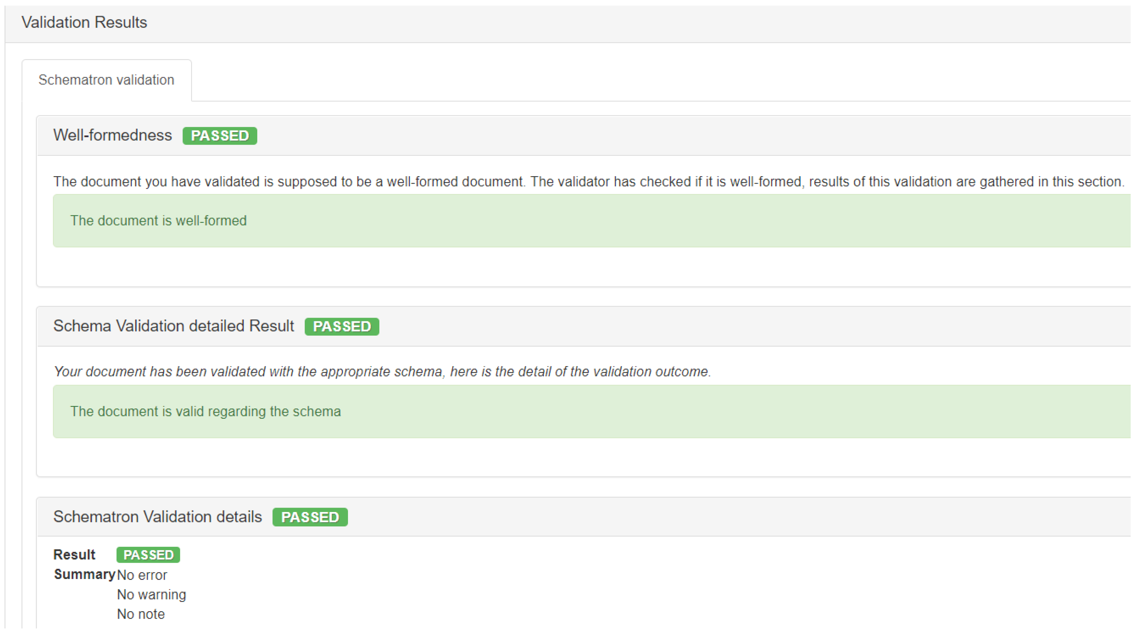
The data packages transferred between system A and B are captured via the Gazelle Proxy and undergo transformation into an XML representation, according to a predefined DFDL schema that converts the ASN.1 encoded binary data blocks into ASCII text. Based on this, conformity assessment as shown in Figure 20 (a screenshot from the external evaluation tool) is performed in three steps, each resulting in either pass or fail. First, the XML document adherence to the XML 1.0 syntax rules (well-formed) is inspected. Secondly, the document is checked against the associated XSD schema. The last step includes content validation applying rules defined in a Schematron.
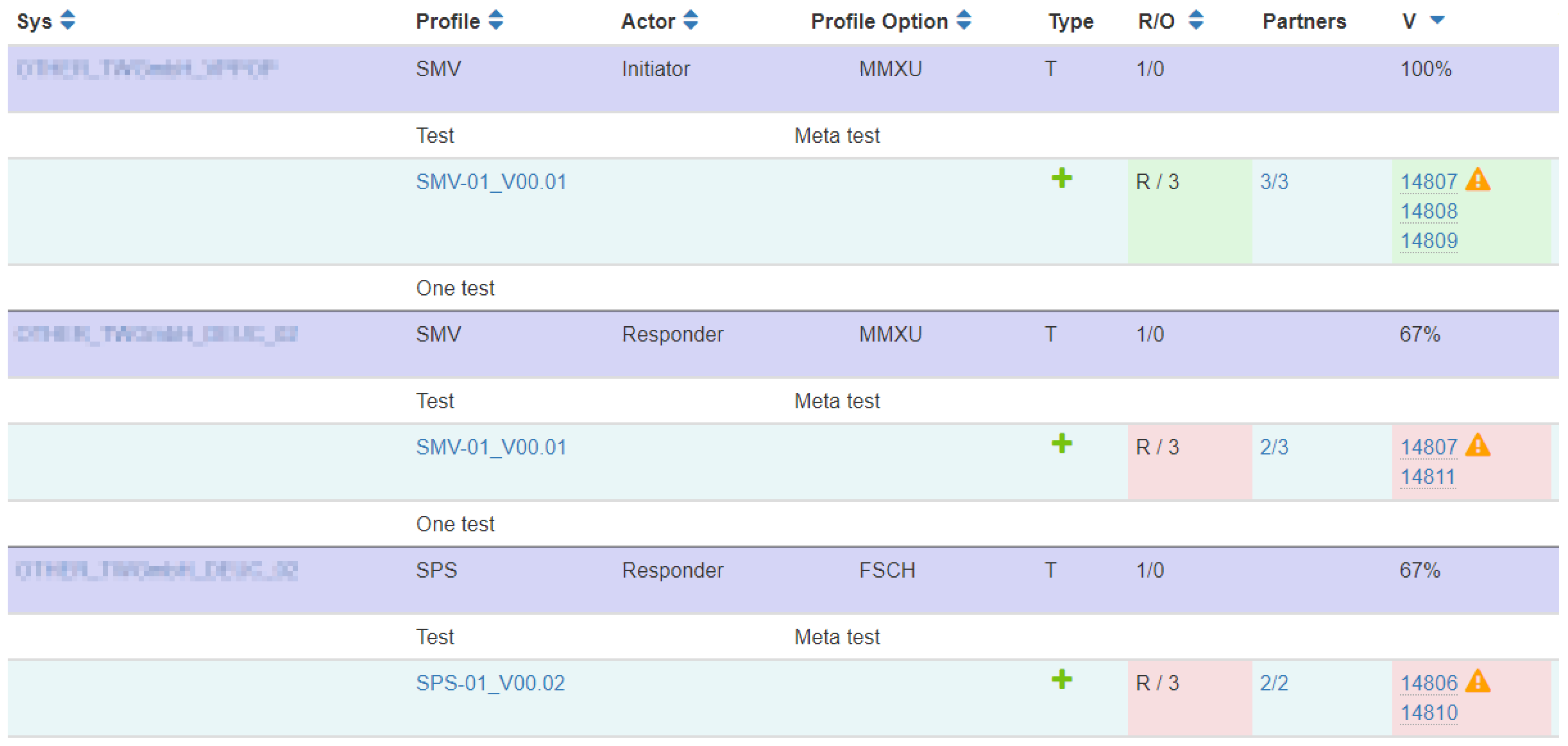
An overview of the interoperability test-results achieved at the Connectathon 2018 is shown in Figure 21 (screenshot from Gazelle). The systems under test supporting given Integration Profiles are listed: Send Measured Values (SMV), Send Planned Schedule (SPS), and Send Asset Configurations (SAC), Their role is either the Initiator or Responder actor, depending on which entity starts the communication. Information about the required number of independent test-runs for receiving an integration statement and the list of different test instances conducted is shown. Individual steps can be opened in the user interface and manually inspected. Altogether, the interoperability testing in the energy domain performed at the Connectathon 2018 comprised of twenty-one tests instances for the three Integration Profiles. Four DEUC and three VPPOP prototypes/systems from four different manufacturers were tested.
7. Conclusions and Outlook
The research presented is based on the design research principle by Hevner et al. [37]. The main principle of the approach taken is to point out the utility of an artefact for a given scope and problem. The scope was to find a meaningful canonical, standardised process to create profiles for interfaces between components of Smart Grids. As of now, no such process existed in the domain of electrical engineering in the context of Smart Grids. There is no standardised way for system-of-systems based interoperability testing. However, a well established design artefact in from of the IHE (Integrating the Healthcare Enterprise) concept existed. The healthcare domain has similar problems motivated form the view of system-of-systems integration. However, it uses different processes, protocols, and data formats and ontology. A particular challenge was to establish these for the Smart Grid domain and to do a first trial of the well-established healthcare originated methodology in the energy domain. Since this particular aspect is not in the scope of the EU and its European Interoperability Framework (EIF), going vertical with established methods, we conducted the first Connectahon Energy using the IHE Gazelle successfully. This has proven to be a first proof of concept and was considered successful form the healthcare experts. Time will show how many interfaces and use cases will emerge with IES compliant profiles to be tested in the coming years.
Based on the experience from the first Connectathon Energy in the Hague 2018, including the preparation time for this test event, one of the lessons learned is strengthening and aligning the test specification within Gazelle with the Integration Profile development. Companies participating in the Connectathon Energy in the Hague reported that some assertions need to be made more restrictive. Besides the refinement of specifications, Gazelle’s feature for pre-Connectathon testing should be considered; i.e., before a face-to-face test event, vendors want to run conformance tests using the IES Gazelle instance by uploading captured message contents/traces for validation. Feedback gathered at Connectathon Energy events will be considered for upcoming events. Besides updated and new test specifications, web-calls shall be scheduled to support interested and registered companies with detailed technical information on how to prepare best and how Gazelle tools can be accessed and used prior to the event. Concerning the upcoming Connectathon Energy end of January 2019 in Vienna, more trial profiles for interoperability and conformance testing have been prepared and are ready to be tested. The new profiles specify how to communicate metered values and schedules using the IEC 60870-5-104 standard in accordance with specification efforts from VHPready.
The IES activity has resulted in becoming part of work done within the ISGAN initiative. The main objective of ISGAN Annex 6 is to establish a long-term vision for the development of future sustainable power systems. The Annex 6 on Power Transmission & Distribution Systems focuses on system-related challenges, with an emphasis on technologies, market solutions, and policies that contribute to the development of system solutions. The work is carried out by a global network of experts and is managed in four Focus Areas: Expansion Planning and Market Analysis, Technology Trends and Deployment, System Operation and Security, and Transmission and Distribution System Interactions. The active dissemination of the IES methodology is an integral part.
IES Europe is listed as activity A4-IA0-5 in the European Strategic Energy Technology-Plan (SET-Plan) as an Implementation Plan Increase the resilience and security of the energy system [38]. This listing supports the opportunity to specify IES Technical Frameworks and Integration Profiles in the course of international R&D projects with great visibility.
Author Contributions
All of the authors have read and approved the final manuscript. The individual contributions of the authors are: 1. Introduction, G.F.; 2. Related Work, M.G., G.F., M.F., R.P. and M.U.; 3. IES workflow overview, M.G. and G.F.; 4. Technical Frameworks, M.G. and G.F.; 5. Testing the interoperability and profile implementation conformance, M.F. and R.P.; 6. Realization of the IES workflow, M.F. and R.P.; 7. Outlook, M.F. and M.U.
Funding
This research was funded by the Austrian Climate and Energy Fund (KLIEN) managed by the Austrian Research Promotion Agency (FFG), under contract number 853693 within the e!MISSION program, 2nd call, of the Austrian Federal Ministry for Transport, Innovation and Technology.
Acknowledgments
The presented work is part of the project Integrating the Energy Systems (IES) Austria supported by the Austrian Climate and Energy Fund (KLIEN) managed by the Austrian Research Promotion Agency (FFG). We thank all team members of the IES project for the support to write this contribution.
Conflicts of Interest
The authors declare no conflict of interest.
Abbreviations
The following abbreviations are used in this manuscript:
| ABB | Architecture Building Block |
| ABB_spec | ABB Specifications |
| ACM | Association for Computing Machinery |
| BAP | Basic Application Profile |
| BAIOP | Basic Application Interoperability Profiles |
| CEN | European Committee for Standardization |
| CENELEC | European Committee for Electrotechnical Standardization |
| CF | Common Feature |
| CG | Coordination Group |
| CO2 | Carbon Dioxide |
| DER | Distributes Energy Resource |
| DEU | Distributed Energy Unit |
| DEUC | Distributed Energy Unit Controller |
| DEUOP | Distributed Energy Unit Operator |
| DFDL | Data Format Description Language |
| DICOM | Digital Imaging and Communications in Medicine |
| DRCT | DER Controller Characteristics |
| DSO | Distribution System Operator |
| DTR | Draft Technical Report |
| EIRA | European Interoperability Reference Architecture |
| ETSI | European Telecommunications Standards Institute |
| FFG | Austrian Research Promotion Agency |
| FIP | Functional Integration Profile |
| FSCH | Functional Schedule |
| GWAC | GridWise Architecture Council |
| HL7 | Health Level 7 |
| ICT | Information and Communication Technology |
| ID | Identification |
| IEC | International Electrotechnical Commission |
| IEEE | Institute of Electrical and Electronics Engineering |
| IES | Integrating the Energy Systems |
| IHE | Integrating the Healthcare Enterprise |
| IP | Internet Protocol |
| ISGAN | International Smart Grids Action Network |
| ISO | International Standardization Organization |
| IT | Information Technology |
| KLIEN | Austrian Climate and Energy Fund |
| LAN | Local Area Network |
| M/490 | European Mandate 490 |
| MMXU | Measurements |
| OASIS | Organization for the Advancement of Structured Information Standards |
| PHR | Personal Health Record |
| RA | Reference Architecture |
| R&D | Research and Development |
| RES | Renewable Energy Source |
| SAC | Send Asset Configuration |
| SBB | Solution Building Blocks |
| SET | Strategic Energy Technology |
| SETIS | Strategic Energy Technologies Information System |
| SG | Smart Grid |
| SGAM | Smart Grid Architecture Model |
| SMV | Send Measured Values |
| SoS | System of Systems |
| SPS | Send Planned Schedule |
| SUT | Systems Under Test |
| TF | Technical Framework |
| TOGAF | The Open Group Architecture Framework |
| TSO | Transmission System Operator |
| UML | Unified Modelling Language |
| VPN | Virtual Private Network |
| VPP | Virtual Power Plant |
| VPPOP | Virtual Power Plant Operator |
| XML | Extensible Markup Language |
| XSD | XML Schema Definition |
References
- Uslar, M.; Specht, M.; Daenekas, C.; Trefke, J.; Rohjans, S.; Gonzalez, J.M.; Rosinger, C.; Bleiker, R. Standardization in Smart Grids; Springer: Berlin/Heidelberg, Germany, 2013. [Google Scholar]
- Ramchurn, S.D.; Vytelingum, P.; Rogers, A.; Jennings, N.R. Putting the ‘Smarts’ into the Smart Grid: A Grand Challenge for Artificial Intelligence. ACM 2012, 55, 86–97. [Google Scholar] [CrossRef]
- Kroposki, B.; Johnson, B.; Zhang, Y.; Gevorgian, V.; Denholm, P.; Hodge, B.M.; Hannegan, B. Achieving a 100% Renewable Grid: Operating Electric Power Systems with Extremely High Levels of Variable Renewable Energy. IEEE Power Energy Mag. 2017, 15, 61–73. [Google Scholar] [CrossRef]
- Steg, L.; Shwom, R.; Dietz, T. What Drives Energy Consumers? Engaging People in a Sustainable Energy Transition. IEEE Power Energy Mag. 2018, 16, 20–28. [Google Scholar] [CrossRef]
- IEEE Standards Board. IEEE Standard Glossary of Software Engineering Terminology; Technical Report; Standards Coordinating Committee of the Computer Society of the IEEE: Los Alamitos, CA, USA, 1990. [Google Scholar]
- Merriam-Webster Incorporated. Definition of Interoperability. Available online: https://www.merriam-webster.com/dictionary/interoperability (accessed on 25 May 2018).
- IES Team. IES—Integrating the Energy System. Available online: www.iesaustria.at (accessed on 30 October 2018).
- Gottschalk, M.; Franzl, G.; Frohner, M.; Pasteka, R.; Uslar, M. Structured workflow achieving interoperable smart energy systems. Energy Inform. 2018. [Google Scholar] [CrossRef]
- European Commission. Digital Single Market. Available online: https://ec.europa.eu/commission/priorities/digital-single-market_en (accessed on 30 May 2018).
- IEC 62559-2:2015. Use Case Methodology—Part 2: Definition of the Templates for Use Cases, Actor List and Requirements List; IEC TC8 Standard; IEC: Geneva, Switzerland, 2015. [Google Scholar]
- Gottschalk, M.; Uslar, M.; Delfs, C. The Use Case and Smart Grid Architecture Model Approach: The IEC 62559-2 Use Case Template and the SGAM Applied in Various Domains; SpringerBriefs in Energy; Springer: Berlin/Heidelberg, Germany, 2017. [Google Scholar]
- CEN-CENELEC-ETSI Smart Grid Coordination Group. First Set of Standards; Technical Report; CEN-CENELEC-ETSI Smart Grid Coordination Group: Brussels, Belgium, 2012. [Google Scholar]
- Englert, H.; Uslar, M. Europäisches Architekturmodell für Smart Grids-Methodik und Anwendung der Ergebnisse der Arbeitsgruppe Referenzarchitektur des EU Normungsmandats M/490. In Proceedings of the Tagungsband VDE-Kongress, Stuttgart, Deutschland, 5–6 November 2012. Technical Report. [Google Scholar]
- SG-CG/RA. Smart Grid Reference Architecture; Technical Report; CEN-CENELEC-ETSI Smart Grid Coordination Group: Brussels, Belgium, 2012. [Google Scholar]
- The Open Group. TOGAF Version 9—The Open Group Architecture Framework (TOGAF), 9th ed.; The Open Group: San Francisco, CA, USA, 2009. [Google Scholar]
- Urbauer, P.; Sauermann, S.; Frohner, M.; Forjan, M.; Pohn, B.; Mense, A. Applicability of IHE/Continua components for PHR systems: Learning from experiences. Comput. Biol. Med. 2015, 59, 186–193. [Google Scholar] [CrossRef] [PubMed]
- Noumeir, R. Integrating the healthcare enterprise process. Int. J. Healthc. Technol. Manag. 2008, 9, 167. [Google Scholar] [CrossRef]
- IHE International. Gazelle—eHealth Test Framework for Interoperability. Available online: https://gazelle.ihe.net/ (accessed on 30 October 2018).
- Frohner, M.; Gottschalk, M.; Franzl, G.; Pasteka, R.; Uslar, M.; Sauermann, S. Smart Grid Interoperability Profiles Development. In Proceedings of the 2017 IEEE International Conference on Smart Grid Communications, Dresden, Germany, 23–26 October 2017. [Google Scholar] [CrossRef]
- Smart Grid Mandate. Methodologies to Facilitate Smart Grid System Interoperability through Standardization, System Design and Testing. Available online: https://www.google.com.tw/url?sa=t&rct=j&q=&esrc=s&source=web&cd=1&cad=rja&uact=8&ved=2ahUKEwie3vD7_3eAhXCEnAKHRGNCyoQFjAAegQIAxAB&url=https%3A%2F%2Fwww.researchgate.net%2Fpublication%2F322752190_Smart_Grid_Interoperability_Testing_Methodology_A_Unified_Approach_Towards_a_European_Framework_for_Developing_Interoperability_Testing_Specifications&usg=AOvVaw1MICQd3PD5VnSUZxHksKpy (accessed on 30 October 2018).
- Wolfgang, B.; Heiko, E. Basic Application Profiles for IEC 61850. 2013. Available online: https://docstore.entsoe.eu/Documents/RDCdocuments/BAP_concept_TC57WG10.pdf (accessed on 30 October 2018).
- Masera, Marcelo. The Role of Interoperability in the Digital Energy Vision. 2017. Available online: https://www.etip-snet.eu/wp-content/uploads/2017/06/2.-The-role-of-Interoperability-Marcelo-Masera.pdf (accessed on 30 October 2018).
- Forsberg, K.; Mooz, H.; Cotterman, H. Visualizing Project Management—Models and Frameworks for Mastering Complex Systems, 3rd ed.; John Wiley & Sons, Inc.: Hoboken, NJ, USA, 2005; pp. 108–116, 242–248, 341–360. [Google Scholar]
- Industry Alliance VHPready e.V. VHPready. Available online: https://www.vhpready.com/ (accessed on 30 November 2018).
- IEC 60870-5-104—Telecontrol Equipment and Systems—Part5-104: Transmission Protocols—Network Access for IEC 60870-5-101 Using Standard Transport Profiles. Available online: https://www.google.com.tw/url?sa=t&rct=j&q=&esrc=s&source=web&cd=2&cad=rja&uact=8&ved=2ahUKEwj81rL6_v3eAhUJfnAKHSfIBgYQFjABegQIBhAB&url=https%3A%2F%2Fwebstore.iec.ch%2Fpublication%2F3746&usg=AOvVaw2LLUacS4XK_It0q8rsKXnt (accessed on 30 October 2018).
- IEC 61850-7-420:2009—Communication Networks and Systems for Power Utility Automation—Part 7-420: Basic Communication Structure—Distributed eNergy Resources Logical Nodes. Available online: https://www.google.com.tw/url?sa=t&rct=j&q=&esrc=s&source=web&cd=1&cad=rja&uact=8&ved=2ahUKEwiZo4jE_v3eAhXYQd4KHX35Ab4QFjAAegQIBRAB&url=https%3A%2F%2Fwebstore.iec.ch%2Fpublication%2F6019&usg=AOvVaw2BLqlPG9vYoFh7SuXlbmGj (accessed on 30 October 2018).
- Eisl, Hubert. ELGA Erfolgreich Gestartet. 2016. Available online: http://ihe-austria.at/elga-erfolgreich-gestartet/ (accessed on 30 October 2018).
- Franzl, G.; Frohner, M.; Gottschalk, M.; Reif, V.; Koch, G.; Berger, A. Interoperabilität im Datenaustausch in der Energiewwirtschaft—Vom Use Case zum Test der Integrationsprofile. In Proceedings of the Symposium Energieinnovation 2018, Graz, Austria, 14–16 February 2018. [Google Scholar] [CrossRef]
- IHE Europe. Whitepaper on Connectathon. The IHE Connectathon. What Is It? How Is It Done? Version 004. Available online: https://www.google.com.tw/url?sa=t&rct=j&q=&esrc=s&source=web&cd=3&cad=rja&uact=8&ved=2ahUKEwjU-t_q_f3eAhWI62EKHT46BAsQFjACegQICBAC&url=https%3A%2F%2Fwww.ihe-europe.net%2Fsites%2Fdefault%2Ffiles%2FWhitePaper_Connectathon_2016.pdf&usg=AOvVaw3vNVAnPQmRWdfV5aSS8e5h (accessed on 30 October 2018).
- ISO DTR 28380-1: Health Informatics—IHE Global Standards Adoption—Part 1: Process. Available online: https://www.google.com.tw/url?sa=t&rct=j&q=&esrc=s&source=web&cd=1&cad=rja&uact=8&ved=2ahUKEwil7-W3_f3eAhUYIIgKHcYsBFYQFjAAegQIAhAB&url=https%3A%2F%2Fwww.iso.org%2Fstandard%2F63383.html&usg=AOvVaw1iuYOVXKoGsFrnfKhE6ucA (accessed on 30 October 2018).
- Europa Analytics. An Introduction to the European Interoperability Reference Architecture (EIRA) v2.1.0. Available online: https://joinup.ec.europa.eu/sites/default/files/distribution/access_url/2018-02/b1859b84-3e86-4e00-a5c4-d87913cdcc6f/EIRA_v2_1_0_Overview.pdf (accessed on 30 October 2018).
- Masi, M.; Pavleska, T.; Aranha, H. Automating Smart Grid Solution Architecture Design. In Proceedings of the 2018 IEEE International Conference on Smart Grid Communications, Aalborg, Denmark, 29–31 October 2018. [Google Scholar]
- The Open Group. Introduction to Building Blocks. Available online: http://www.opengroup.org/public/arch/p4/bbs/bbs_intro.htm (accessed on 30 May 2018).
- IHE Europe. Gazelle | IHE Europe. 2018. Available online: https://www.ihe-europe.net/testing-IHE/gazelle (accessed on 30 October 2018).
- Open Grid Forum. Data Format Description Language (DFDL) v1.0 Specification. Available online: https://www.ogf.org/documents/GFD.207.pdf (accessed on 30 October 2018).
- The Apache Software Foundation. Apache Daffodil (Incubating) | Getting Started. Available online: https://daffodil.apache.org/getting-started/ (accessed on 30 October 2018).
- Hevner, A.; Chatterjee, S. Design Research in Information Systems; Integrated Series in Information Systems 22; Springer: Berlin/Heidelberg, Germany, 2010; pp. 9–21. [Google Scholar]
- Temporary Working Group 4—Increase the Resilience and Security of The Energy System. Strategic Energy Technology Plan—Implementation Plan—Final Version—15.01.2018; Technical Report; European Commission—SETIS: Brussels, Belgium, 2018.
Figure 1.
The Smart Grid: Services based on Information and Communication Technology (ICT) are added to the established energy management paradigm to support efficient grid control in the presence of distributed energy resources (DER).
Figure 1.
The Smart Grid: Services based on Information and Communication Technology (ICT) are added to the established energy management paradigm to support efficient grid control in the presence of distributed energy resources (DER).

Figure 2.
The Smart Grid Architecture Model [12]: a three-dimensional positioning scheme to identify and confine features and systems of smart grids, © CEN/CENELEC, reproduced with permission.
Figure 2.
The Smart Grid Architecture Model [12]: a three-dimensional positioning scheme to identify and confine features and systems of smart grids, © CEN/CENELEC, reproduced with permission.

Figure 3.
The Open Group Architecture Framework: a logical, cyclic, step-by-step requirements elicitation guideline.
Figure 3.
The Open Group Architecture Framework: a logical, cyclic, step-by-step requirements elicitation guideline.

Figure 4.
Testing interoperability and validating the conformance with Integration Profiles.

Figure 5.
The IES process to interoperability are, in brief, four steps: identify → specify → test → sell.
Figure 5.
The IES process to interoperability are, in brief, four steps: identify → specify → test → sell.

Figure 6.
Functional Committees: coordinating, managing, and executing bodies that drive and manage the IES based process to integrate energy enterprises.
Figure 6.
Functional Committees: coordinating, managing, and executing bodies that drive and manage the IES based process to integrate energy enterprises.

Figure 7.
The Document structure of Technical Frameworks: a top-down approach from Use Cases definition to Integration Profiles specification.
Figure 7.
The Document structure of Technical Frameworks: a top-down approach from Use Cases definition to Integration Profiles specification.

Figure 8.
A Use Case Template excerpt showing three parts: (top) Use Case identifier, relations, and name, (middle) narrative definition of the Use Case, and (bottom) interaction steps and their allocation.
Figure 8.
A Use Case Template excerpt showing three parts: (top) Use Case identifier, relations, and name, (middle) narrative definition of the Use Case, and (bottom) interaction steps and their allocation.

Figure 9.
Positioning of features in the three-dimensional SGAM: selected VPP features mapped onto the three reference designation axes.
Figure 9.
Positioning of features in the three-dimensional SGAM: selected VPP features mapped onto the three reference designation axes.

Figure 10.
Use Case Diagram: Meta-Actors (here: Virtual Power Plant Operator, Distributed Energy Units Operator, Distributed Energy Unit Controller) connected to Use Case specific functions.
Figure 10.
Use Case Diagram: Meta-Actors (here: Virtual Power Plant Operator, Distributed Energy Units Operator, Distributed Energy Unit Controller) connected to Use Case specific functions.

Figure 11.
Actors–Transactions Diagram: Meta-Actors connected by the functions to be specified in Volume Two for interoperability.
Figure 11.
Actors–Transactions Diagram: Meta-Actors connected by the functions to be specified in Volume Two for interoperability.

Figure 12.
The Extended Document Structure: Technical Frameworks are collections of many parts, each assigned to a layer, that may be individually extended and adjusted following changing demands and the progress of technologies over time.
Figure 12.
The Extended Document Structure: Technical Frameworks are collections of many parts, each assigned to a layer, that may be individually extended and adjusted following changing demands and the progress of technologies over time.

Figure 13.
The Open Group Building Blocks: coarse relation of Business Function, Integration Profiles, etc. to Architecture and Solution Building Blocks used by TOGAF/EIRA.
Figure 13.
The Open Group Building Blocks: coarse relation of Business Function, Integration Profiles, etc. to Architecture and Solution Building Blocks used by TOGAF/EIRA.

Figure 14.
Common Features: bundling highly flexible features as provided by modern standards.

Figure 15.
The three pillars of the IES approach: identification and specification, peer-to-peer testing, public available specifications and results (Open Access).
Figure 15.
The three pillars of the IES approach: identification and specification, peer-to-peer testing, public available specifications and results (Open Access).

Figure 16.
Peer-to-peer interoperability testing: independent implementations get connected and their cooperation is evaluated, including verification of exchanged messages (formats and contents).
Figure 16.
Peer-to-peer interoperability testing: independent implementations get connected and their cooperation is evaluated, including verification of exchanged messages (formats and contents).

Figure 17.
Derailing communication via Gazelle proxy service: port numbers are assigned to the systems prior testing, transferred messages are captured to undergo validation.
Figure 17.
Derailing communication via Gazelle proxy service: port numbers are assigned to the systems prior testing, transferred messages are captured to undergo validation.

Figure 18.
Schematic set-up for interoperability testing: directional communication is routed through the VPN connection to capture, transform and validate messages using the according Gazelle tools.
Figure 18.
Schematic set-up for interoperability testing: directional communication is routed through the VPN connection to capture, transform and validate messages using the according Gazelle tools.

Figure 19.
Sequence diagram sketch for the in total eleven test steps to be evaluated for the transaction sends FSCH in accordance with IEC 61850.
Figure 19.
Sequence diagram sketch for the in total eleven test steps to be evaluated for the transaction sends FSCH in accordance with IEC 61850.

Figure 20.
External validation service result showing conformity assessment for captured messages.

Figure 21.
Connectathon 2018 test-results: the VPPOP, DEUOP and DEUC communication interfaces from four different manufacturers were tested on interoperability and compliance with the SMV, SPS and SAC Integration Profile (Gazelle screenshot).
Figure 21.
Connectathon 2018 test-results: the VPPOP, DEUOP and DEUC communication interfaces from four different manufacturers were tested on interoperability and compliance with the SMV, SPS and SAC Integration Profile (Gazelle screenshot).


Table 1.
The eight parts of the Use Case template—content and viewpoint.
| Use Case Template | Content | Viewpoint | |
|---|---|---|---|
| 1 | Description | General info: identifier, name, non-technical description, boundaries, objectives, etc. | management perspective |
| 2 | Diagram | Visual representation of the Use Case: e.g., UML Use Case Diagrams, Sequence Diagrams. | |
| 3 | Technical details | List of actors (humans/systems) involved in the Use Case with brief role explanation. | ICT experts |
| 4 | Step-by-step analysis | Technical description of implementation: data exchanged, information objects, requirements. | |
| 5 | Information exchanged | List of information objects exchanged between actors. | |
| 6 | Requirements | List of requirements that have to be adhered to actors and information objects. | |
| 7 | Common terms and definitions | Glossary of the Use Case: define the terms used. | stakeholders (if necessary) |
| 8 | Custom information | Further information/explanation that cannot be addressed elsewhere. | |
© 2018 by the authors. Licensee MDPI, Basel, Switzerland. This article is an open access article distributed under the terms and conditions of the Creative Commons Attribution (CC BY) license (http://creativecommons.org/licenses/by/4.0/).
Share and Cite
MDPI and ACS Style
Gottschalk, M.; Franzl, G.; Frohner, M.; Pasteka, R.; Uslar, M. From Integration Profiles to Interoperability Testing for Smart Energy Systems at Connectathon Energy. Energies 2018, 11, 3375. https://doi.org/10.3390/en11123375
AMA Style
Gottschalk M, Franzl G, Frohner M, Pasteka R, Uslar M. From Integration Profiles to Interoperability Testing for Smart Energy Systems at Connectathon Energy. Energies. 2018; 11(12):3375. https://doi.org/10.3390/en11123375
Chicago/Turabian StyleGottschalk, Marion, Gerald Franzl, Matthias Frohner, Richard Pasteka, and Mathias Uslar. 2018. "From Integration Profiles to Interoperability Testing for Smart Energy Systems at Connectathon Energy" Energies 11, no. 12: 3375. https://doi.org/10.3390/en11123375
Note that from the first issue of 2016, this journal uses article numbers instead of page numbers. See further details here.