1. Introduction
Recently, the voltage source converter based high voltage direct current (VSC-HVDC) is widely used in dc transmission, renewable energy generation, island network supply and other fields [
1,
2,
3,
4]. In general control scheme of VSC-HVDC, the three-phase AC grid voltage is usually assumed to be balanced. However, once the unbalanced grid conditions occur (e.g., due to AC grid voltage unbalance and unsymmetrical faults), the converter will operate in abnormal condition and the negative sequence components in voltage and current will do great harm to system operation. If no compensation measures are adopted, the double frequency ripples will appear in the output power of VSC, which affects output quality of the converter [
5,
6,
7] and may even make the converter malfunction. Therefore, how to suppress the double frequency ripples under unbalanced grid conditions becomes a hot topic in the research of VSC-HVDC control.
To suppress the double frequency power ripples, the additional active power filter is utilized in Reference [
8,
9,
10] to eliminate the asymmetric components. The active power filter has ideal performance in regulating asymmetrical components but the cost input is high. Hence improving the control strategy of the converter is the mainstream research on the suppression of double frequency power ripples. The VSC control strategies in ideal balance grid have been relatively mature and the most common schemes are the voltage oriented control (VOC). The existing unbalance control research of VSC under the framework of VOC is mainly realized by obtaining the control reference value according to some kind of control objective (e.g., elimination of active power ripple, reactive power ripple or negative-sequence current component) and tracking this reference value with suitable method [
11,
12]. In Reference [
13], a novel method of separating the instantaneous positive and negative sequence components is proposed and well applied for different control objectives of VSC under unbalanced grid voltage. In Reference [
14], an optimal active and reactive power control is proposed to achieve multi-objectives for VSC-HVDC under unbalanced grid voltage conditions. A flexible control strategy is proposed in Reference [
15] for oscillation control of the active and reactive power by introducing a control parameter k. In Reference [
16], an improved model predictive current control for VSC is presented when unbalanced grid voltages occur to reduce power fluctuations. In Reference [
17], a direct power control for grid-connected VSC under unbalanced network is proposed by applying a virtual phase angle for coordinated transformations. The optimal power control strategies for VSC-HVDC systems under unbalanced grid voltage conditions are proposed in Reference [
18,
19], which enable the system to provide flexible power control. In Reference [
20], a power control of VSC-HVDC converters is presented to limit the influence of AC unbalanced faults on multi-terminal DC grids. In Reference [
21], a novel unified dynamic model and control strategy are presented to improve the power quality for VSC-HVDC under unbalanced grid conditions. These control strategies are verified to be effective but the fluctuations of active and reactive power cannot be suppressed at the same time.
For past few years, the passivity-based control has attracted more and more attentions because of the flexible adjustment and simplified control structure and has been applied in power converter control [
22,
23]. The passivity-based control of the doubly fed induction generator under unbalanced grid voltage is proposed in Reference [
24]. However, the passivity-based control is applied to replace the traditional PI (Proportional-Integral) control for system response improvement instead of eliminating the double frequency ripple power. Therefore, the double frequency ripples in active and reactive power still cannot be suppressed simultaneously. On the other hand, although the passivity-based control gives the controller design by configuring system energy and injecting damping to achieve the satisfactory transient response, it is sensitive to unmodeled dynamics and model errors. To handle the issue, a perturbation observer-based passivity-based control is proposed in Reference [
25] but the implementation of high-order observer brings in serious noise and complicates system structure, which means the enhanced passivity-based control also needs further study.
In this paper, a power compensation strategy to suppress the double frequency ripples in active and reactive power of VSC-HVDC systems under unbalanced grid voltage conditions is proposed. The main work of this paper can be drawn as:
(1) The mathematical control equations of the double frequency ripple power of VSC under unbalanced grid conditions are derived and established. In the equations, the dynamic behaviors of the double frequency ripples in active and reactive power are regarded as being driven by current-relevant components and voltage-relevant components, which can be controlled respectively for double frequency ripple suppression.
(2) Based on the established control equations, a power compensation control strategy of VSC-HVDC is proposed via the passivity-based control with disturbance observer. The passivity-based control is responsible for the tracking control of current-relevant components with the expected value, while the disturbance observer focuses on the compensation of the voltage-relevant components. With this control strategy, the double frequency ripples in active and reactive power of VSC-HVDC under unbalanced grid conditions are suppressed simultaneously and system performance is significantly enhanced with the implementation of the disturbance observer in the passivity-based control.
Theoretical stability analysis and simulations of a two-terminal VSC-HVDC system on PSCAD/EMTDC verify the validity and superiority of the proposed control strategy.
2. Analysis and Control Equations Establishment of Double Frequency Ripple power of VSC
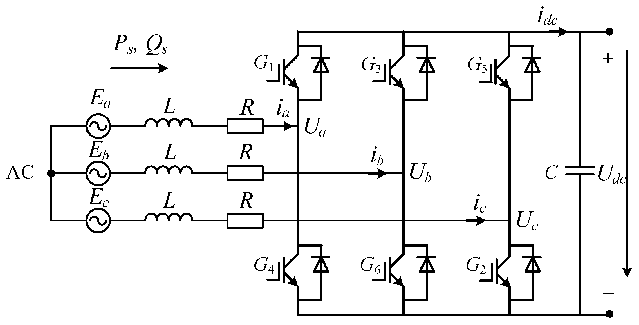
The VSC structure adopted in this paper is the two-level topology and shown in
Figure 1. The representations of the variables in
Figure 1 are shown in the Nomenclature Section. Although the modular multilevel converter (MMC) is recognized as the promising converter technology applied in high-voltage and high-power transmission technology, the system-level control of MMC is similar to that in two-level converter since they have same vector control model in dq coordinate system [
26], which mean the response characteristics of the two converters under unbalanced grid conditions are also same. Therefore, the two-level converter is used as the study object in this paper for explicit explanations.
Under balanced grid voltage condition, the mathematical model of VSC in synchronous rotating reference frame is [
11]
When asymmetric fault occurs in the grid, the dissymmetry in system electrical quantities is mainly caused by negative sequence components, since the zero sequence components are isolated by the Y/Δ transformer in the grid side. Considering that in the synchronous rotating reference frame, the positive sequence component is equal to the dc component, while the negative sequence component is equal to the double frequency component, the double frequency ripple power in the forward direction dq rotating frame can be written as (2) according to [
17] (
axis is chosen to be coincided with grid voltage vector)
where the right subscript “0” stands for dc component and “2” stands for double frequency component. It is seen from (2) that the factors that cause the double frequency ripples in the output power include the double frequency components of grid voltage (
and
) and the double frequency components of VSC current (
and
). Therefore, the double frequency ripple power can be regard as the results driven by the current-relevant components and voltage-relevant components which can be described as
where
,
,
and
are defined as
To control double frequency ripple power, take the derivative of (4). Since the derivative of dc component is zero, it results in
Since the independent control equation of VSC double frequency voltage can be derived as
By substituting (6) into (5), it results in
Furtherly, the differential equations which take double frequency power
and
as state variables can be obtained as
where
and
satisfy
,
. Let
and
be defined as
In (9), the voltage-relevant components that cause the double frequency power ripples are included in
and
, which can be regarded as the “double frequency voltage disturbance” of the differential Equations (8). Meanwhile, to furtherly improve the robustness of control system, the error terms
and
are introduced in the disturbances
and
to describe the unmodeled dynamics including modelling errors and unknown time-varying external disturbances. Then it yields that
Finally, the control equations of the double frequency ripple power can be depicted by
In (11), and reflect the influence of voltage-relevant components and unmodeled dynamics on the double frequency ripple power. Apart from and , the control Equation (11) reflect the double frequency ripple behaviors caused by current-relevant components. Hence through proper double frequency power compensation control based on (11), the current-relevant and voltage-relevant components that cause double frequency ripples can be suppressed simultaneously.
3. Power Compensation Strategy for VSC-HVDC via Passivity-Based Control with Disturbance Observer
In normal condition, the common vector double loop control is adopted in VSC for desired control aims. However, under unbalanced grid voltage, a power compensation controller is needed to suppress the double frequency power ripples with no impact on the normal operation of VSC. The compensation strategy should be effective in controlling the double frequency components of the unbalanced voltage and current to compensate the output voltage of inner loop PI control. In this paper, the passivity-based control with disturbance observer are proposed to form the power compensation control, which serves as the auxiliary adjustment of VSC under unbalanced grid condition. The design of passivity-based control aims at minimizing the double frequency ripple power and with the double frequency voltage disturbance and observed and compensated in the control scheme.
3.1. PCHD Model of the VSC-HVDC Systems and the Passivity-Based Control Strategy
Consider the PCHD (Port-Controlled Hamiltonian with Dissipation) model [
23] of control Equation (11) described as
where
,
and
denote the system state, the control input and the system output, respectively. It is noted that with the positive defined Hamiltonian function
to be system storage function, the system (12) is passive from the input
to output
. The system state and input variables are shown as
The disturbance
and
is involved in the control input, which means
and
. Then the Hamiltonian function
are obtained as
The interconnection matrix and damping matrix shown in (15) satisfy
and
The control objective of the passivity-based control based on PCHD model is to seek a control input
to ensure that the closed-loop system (12) is asymptotically stable within the desired equilibrium point
To achieve the control objective that system (12) can be asymptotically stable, a closed-loop desired Hamiltonian function
with the feedback control
should be considered so that system energy is minimum in the equilibrium point and that the system can be described by the equations.
where
and
satisfy
Designers should have high freedom in selecting the matrix
,
and
to satisfy the desired objective. For general speaking, it is defined that
The closed-loop desired Hamiltonian function
is taken as
Then it can be obtained in (21) by substituting (18), (19) and (20) into (12)
To ensure that (21) is equivalent to system Equation (17), the following relationship is forced to be satisfied
Hence the feedback control is depicted by
Furtherly it can be obtained that
With the control law in (23), it can be proved that
When
, it has
and
, which proves that
takes the minimal value at
. Therefore, the minimum system energy is achieved and the closed-loop system tends to be asymptotically stable within the desired equilibrium point [
23].
3.2. Robust Passivity-Based Control Strategy via Disturbance Observer
In the passivity-based control law (24), it is seen that the disturbance value and must be available to realize the asymptotical stability of the closed-loop system. From the definition of and in (10), if the unmodeled dynamics and errors ( and ) are not considered, the terms and can be calculated through (9). Nevertheless, to improve the robustness of controller regarding to unmodeled dynamics and errors and to avoid complicated calculation of (9), terms and are estimated online via the double-disturbance observer (DDO) to eliminate and compensate the disturbance.
It is known that the disturbance
and
are time-varying hence they can be viewed as the polynomials with respect to time
according to Taylor’s formula
where
(
= 0, 1, 2, …) is the constant coefficient of the polynomial. As it can be seen, the dynamic behavior of the time-varying disturbance is approximated as a high-order polynomial. Nevertheless, considering that the noise becomes more serious and the structure becomes more complicated in higher order observer, a first-order observer is adopted for the disturbance observation [
27]. Then the standard form of the state equation and the output equation of (11) are represented as follows
where
A double-disturbance observer (DDO), which is the extension form of the observer in Reference [
28], is introduced here to estimate the disturbance in (28)
where
and
are given as
If the observation error is defined as
Then the dynamic equation of the observation error is depicted by
To ensure that the above disturbance equation is globally asymptotically stable, the observer gain should be chosen as
, which means that the observation value
can converge to the actual value exponentially. Furtherly the relationship of the estimated value and actual value of the disturbances are
where
and
;
is the differential operator. In order to realize the estimation at a certain speed and accuracy, the observer gains should be large to make the dynamic response of the observer faster than that of the control system. But the system may subject to saturation or noise during implementation if
and
are too large. Therefore, the observer gains need to be chosen properly to realize this balance.
In order to eliminate and compensate the disturbance, a compensation control
is designed and added into the closed loop structure base on the estimated disturbance. The compensation control
satisfies
Along with the disturbance compensation value, the power compensation control is
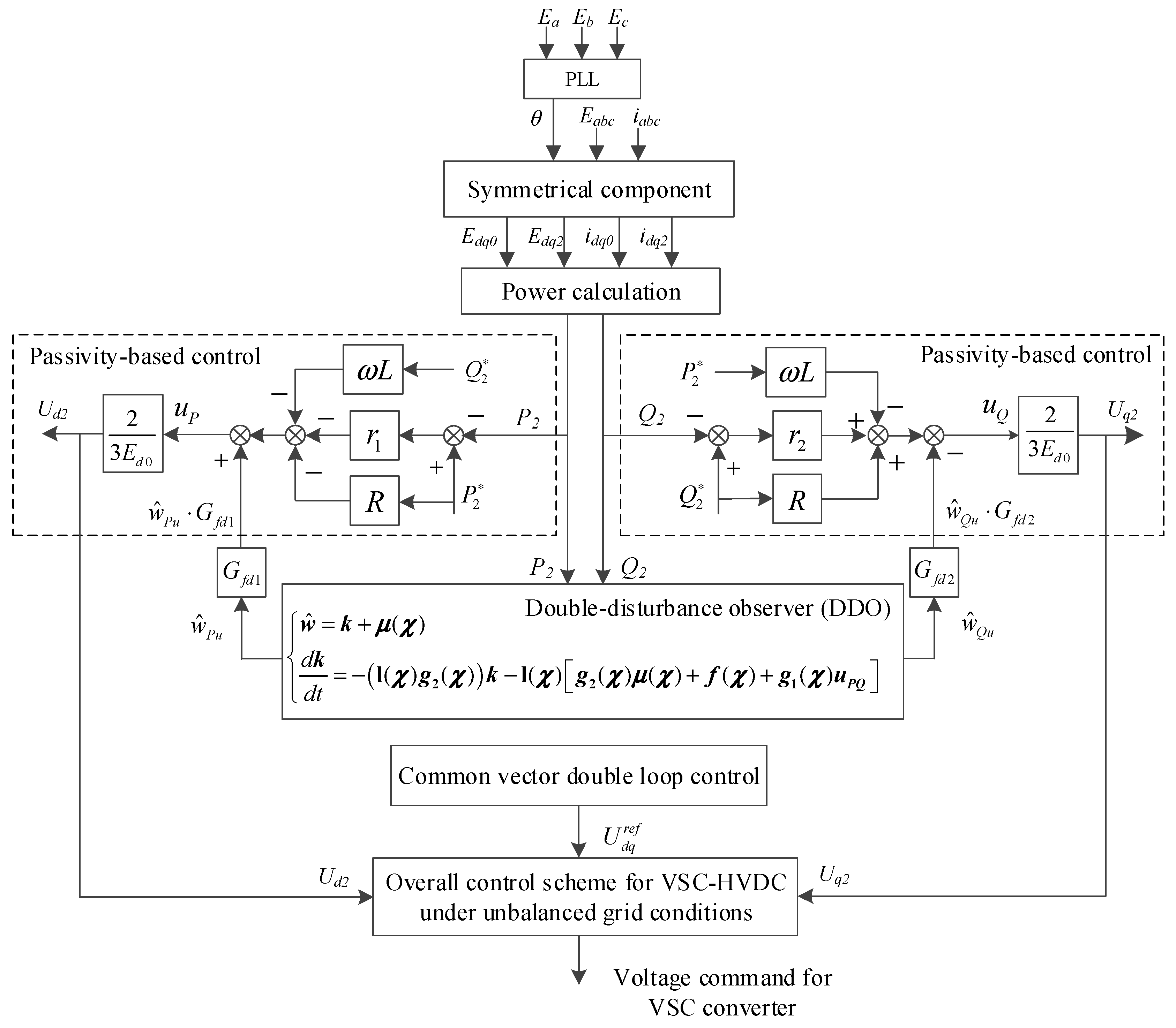
The overall block diagram of the proposed passivity-based control with DDO is shown in
Figure 2. To apply the proposed control scheme, electrical measurements are acquired for the dq transformation and calculation of the double frequency power
and
. Then the proposed passivity-based power compensation control via the disturbance observer can be realized according to the above mathematical derivation. The obtained unbalanced control signals
and
together with the modulation voltage signals from the common vector double loop control form the overall control scheme for VSC-HVDC under unbalanced grid conditions and finally, the voltage command for VSC converter can be available.
3.3. Stability Analysis of the Proposed Power Compensation Strategy via Passivity-Based Control with Disturbance Observer
The stability analysis of the proposed power compensation strategy via passivity-based control with disturbance observer is conducted in this part. From (29) and (30), the estimated disturbance value can be depicted as
It can be seen in (36) that the active and reactive disturbance components are associated with both the double frequency active and reactive power, which means (36) is the MIMO (Multiple Input Multiple Output) system equation. By substituting (36) into (35), it can be obtained as
Furtherly, by substituting (37) into system Equation (11) and by replacing the state variables with the small disturbance variables, it can be depicted by
where △ is defined as the small signal disturbance of each variable and
GM is derived as
The zero-pole theory of the MIMO system [
29] points out that, for a system with transfer function matrix
, the pole polynomial
corresponding to a minimal realization is the least common denominator of all non-identically-zero minors of all orders of
and the zero polynomial
corresponding to a minimal realization is the greatest common divisor of all the numerators of all order-r minors of
, where
is the normal rank of
, provided that these minors are adjusted in such a way as to have the pole polynomial
as their denominators. According to this theory, the zero and pole polynomials of
in (39) are
Then the zero-pole map of the closed-loop system can be obtained and the system stability can be determined according to the root locus curve of the predominant pole.
When the basic parameter values in (40) are selected as stated in
Section 4 for system control, the zero-pole maps of
are plotted in
Figure 3. It is known from (40) that there are four poles of
, among which two are determined by
and
(namely
) and two are determined by
and
(namely
). As seen in
Figure 3, the poles of the closed-loop transfer function are all located in the left half of the imaginary axis and ensure a stable system. From
Figure 3a,b different values of
and
have an effect on the pole positions of
and system dynamics as a result. During the increasing of
and
, poles
moves away from the imaginary axis and may be located to the two sides of real axis. Hence the dynamic response gets faster and oscillation may occur. When
and
get too much larger, the poles
are too much away from the imaginary axis and the predominant effect is attenuated. From
Figure 3c,d it is seen that the observer gains
and
of the DDO also have impacts on system dynamic response. When
and
are increasing, poles
are located in the real axis and moves away from the imaginary axis, which means system dynamic response gets faster. The predominant poles of
are determined by the poles distribution of
and
, which indicates that proper parameters should be chosen for superior system dynamic performance.
4. Simulation Results
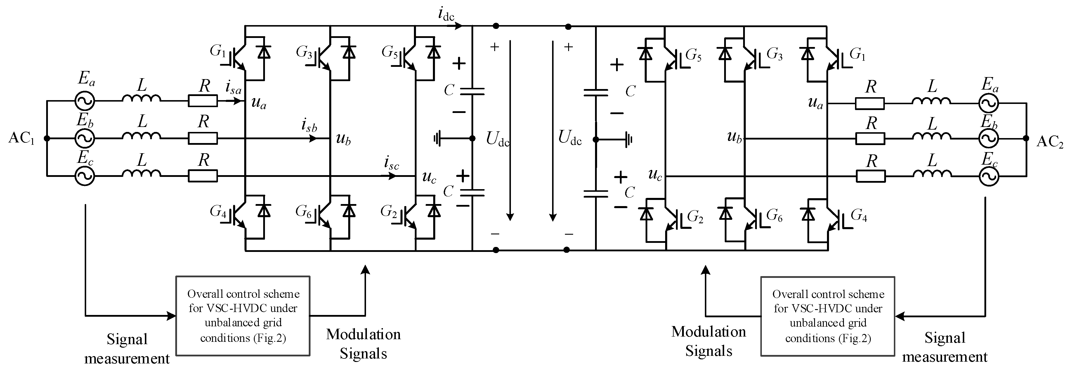
To verify the validity of the proposed control strategy, the dc transmission simulation model with a two-terminal VSC-based converter shown in
Figure 4 is established in PSCAD/EMTDC. The rated VSC line voltage and DC bus voltage are 230 kV and 330 kV, respectively. The passivity parameters
and
are set as 50 and 30, while the observer gain
and
are set as 150 and 200. To reflect the superiority of the proposed control, the comparison cases are set in the simulations. However, since most existing control strategies are ineffectual in suppressing the active and reactive power ripples at the same time, we adopt a resonance controller with properly adjusted parameters [
13] as the conventional compensation control for comparison. This resonance control is also implemented based on the double frequency ripple power control Equation (8) but superior system response cannot be achieved compared with the proposed control strategy according to the simulation results.
4.1. Case 1
In this case, the suppression performance of the double frequency ripples with different control strategies is tested. Before 2.5 s, the system operates under normal grid condition. At time 2.5 s, the B phase and C phase voltage of source AC
2 have a drop of 4.23 kV (50%) shown in
Figure 5. As for the control system, it remains unchanged with the common vector double loop control during 2.5 s to 3.5 s. After 3.5 s, the proposed power compensation strategy and the conventional resonance compensation strategy are added as the auxiliary controllers respectively for the suppression of the double frequency ripples. The simulation results are shown in
Figure 6,
Figure 7 and
Figure 8.
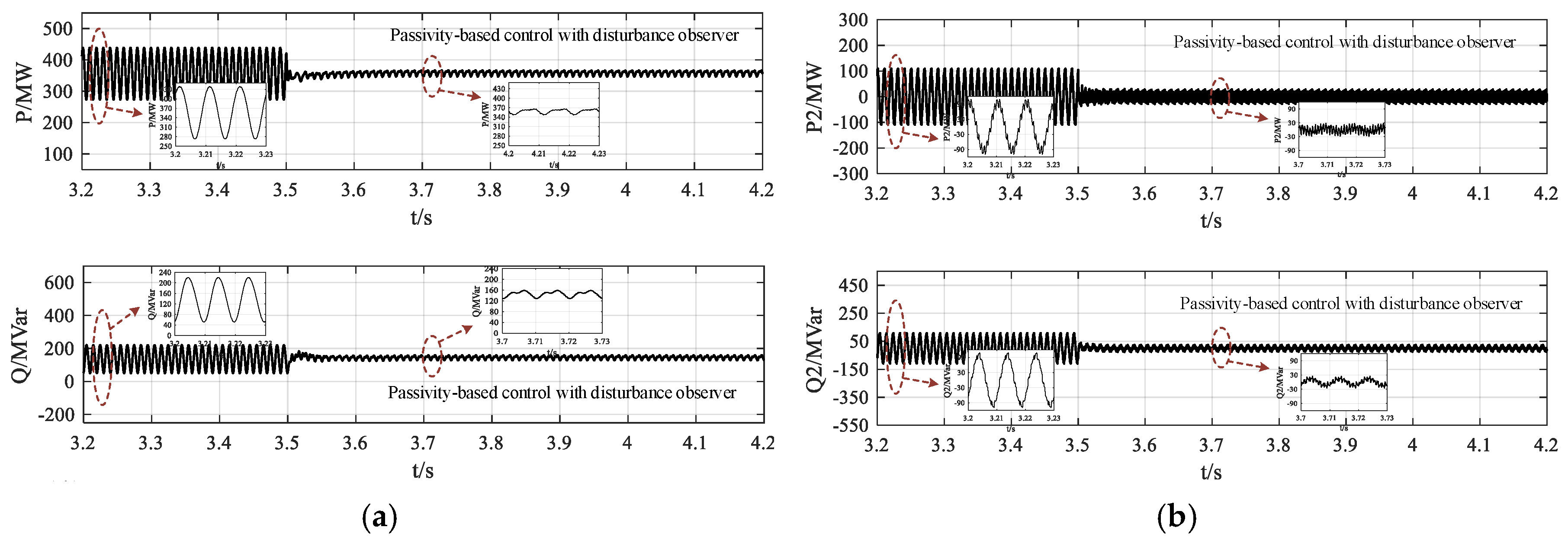
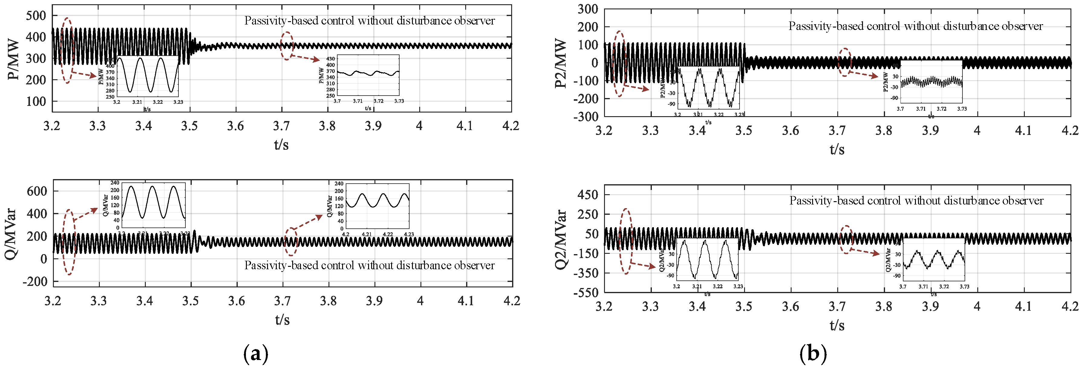
It is seen from the simulation results that under unbalanced grid conditions with no auxiliary power compensation strategy (2.5–3.5 s), the double frequency ripples with large amplitudes appear in the active and reactive power. By comparing
Figure 6 and
Figure 7, it is known that both the proposed passivity-based power compensation strategy (with the disturbance observer) and the conventional resonance compensation strategy can suppress the double frequency ripples in active and reactive power simultaneously, which verify the effectiveness of the established double frequency ripple power control Equation (8). Nevertheless, the steady-state suppression performance of the proposed strategy is better than conventional strategy through the partial enlarged figures in
Figure 6 and
Figure 7. More significantly, the dynamic response at 3.5 s of the proposed compensation strategy is much better than the conventional resonance compensation strategy.
Figure 6 shows that the active and reactive power reach to stable state with much large overshoot and longer transient time under the conventional strategy. Therefore, the effectiveness of the proposed passivity-based control with disturbance observer in suppressing the double frequency power ripples are verified with superior dynamic response.
To furtherly show the superior performance of the proposed passivity-based power compensation strategy with disturbance observer, the simulations with only passivity-based control is shown in
Figure 8. In this scheme, the double-frequency voltage disturbances
and
are calculated through (9) instead of the observer. It can be seen from
Figure 8 that the dynamic response and the suppression performance both become worse compared with that in
Figure 7. The observed and calculated values of the double-frequency voltage disturbance
and
shown in
Figure 9 indicate that there exists difference between the observed and calculated values caused by modelling errors and external impacts, which cause the performance degradation of the passivity-based control with calculated values of
and
. It can be concluded that the response performance of the passivity-based power compensation strategy is significantly improved with the implementation of disturbance observer.
4.2. Case 2
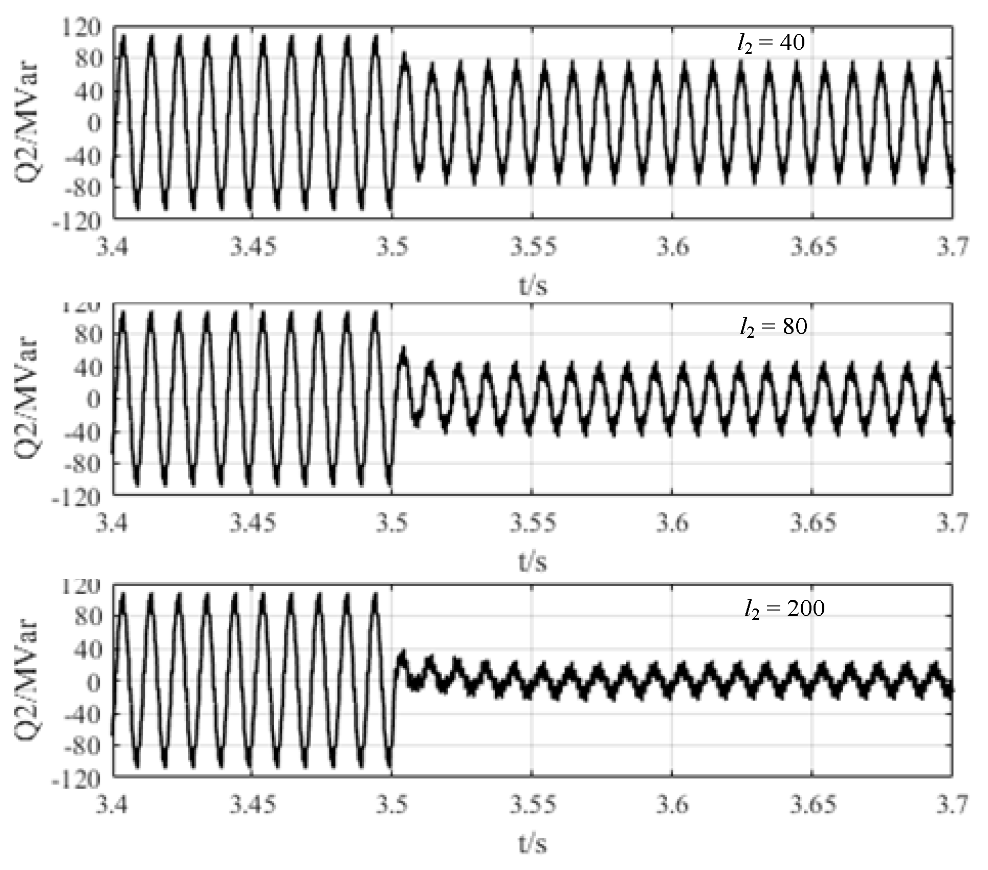
To verify the control effects of the proposed strategy with different control parameters, the simulation results of the double frequency power ripples (take reactive
as an example) under the proposed passivity-based power compensation strategy via disturbance observer with different parameters are shown in
Figure 10 and
Figure 11.
Figure 10 shows the simulation results of the double frequency ripples in reactive power with different passivity parameter
. It indicates that during the increasing of
, power oscillation may occur and the control effect is attenuated (marked in red in
Figure 10) and this depends on the pole positions caused by specific value of
which also confirms the previous theoretical analysis. From
Figure 11, it is seen that different observer gains have significant impacts on system performance and control effects will be weakened if the observer gain is too small. Therefore, with properly chosen passivity parameters and observer gains, expected suppression performance and dynamic response can be obtained under the proposed passivity-based power compensation strategy with disturbance observer.
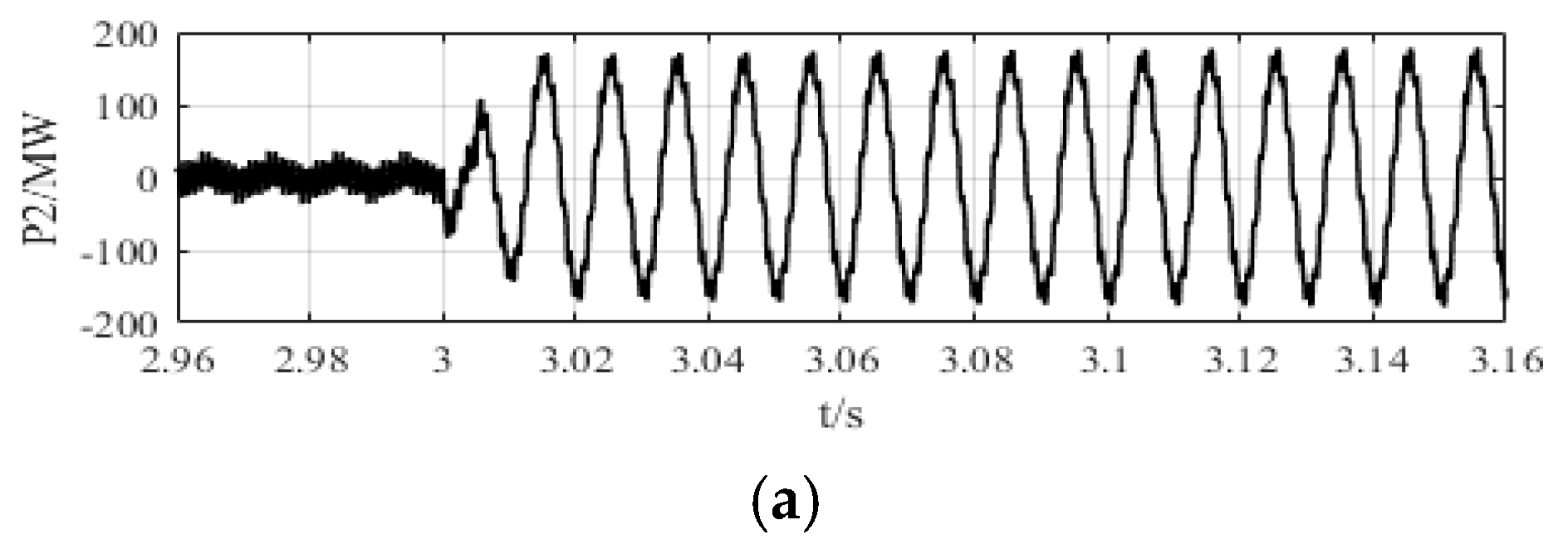
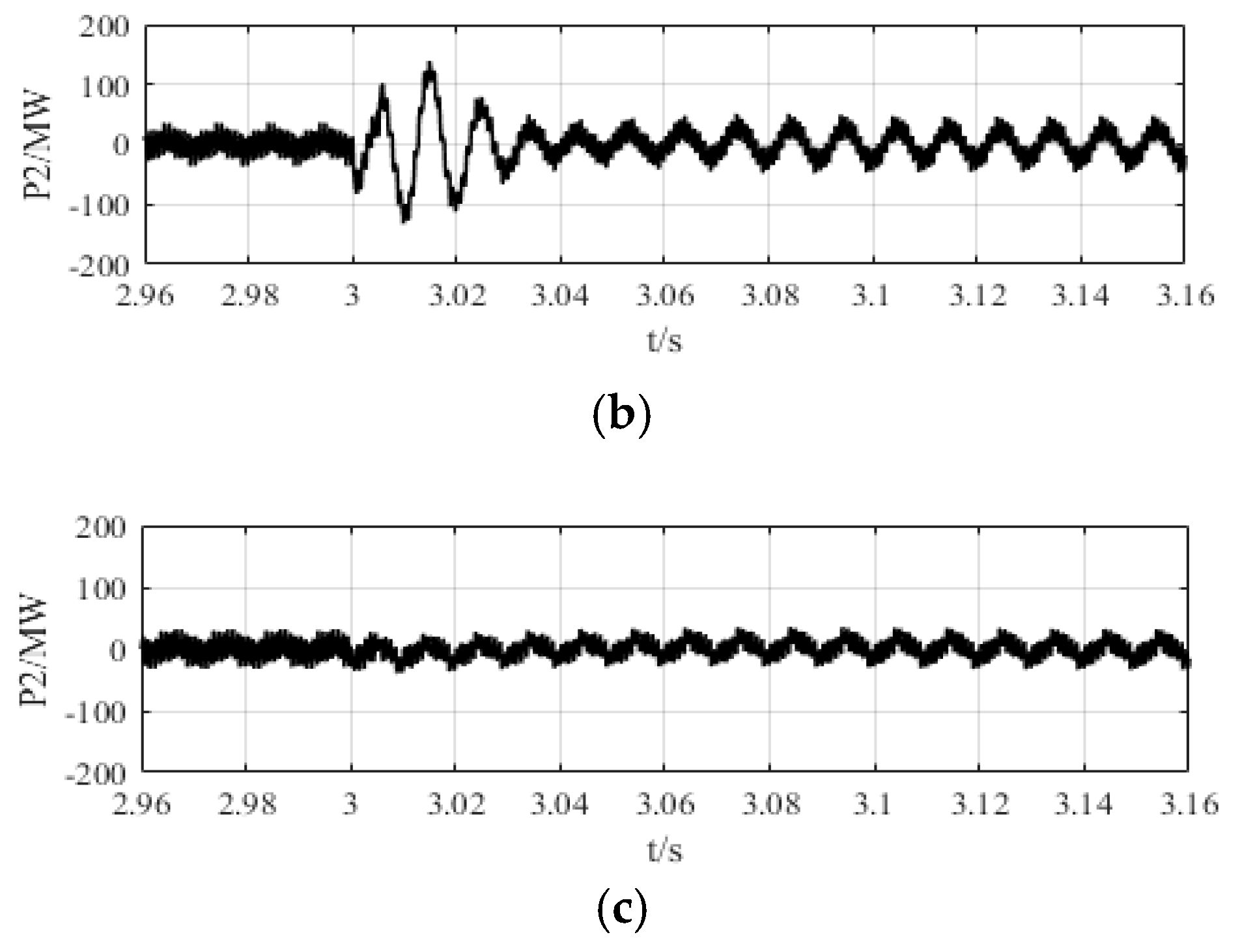
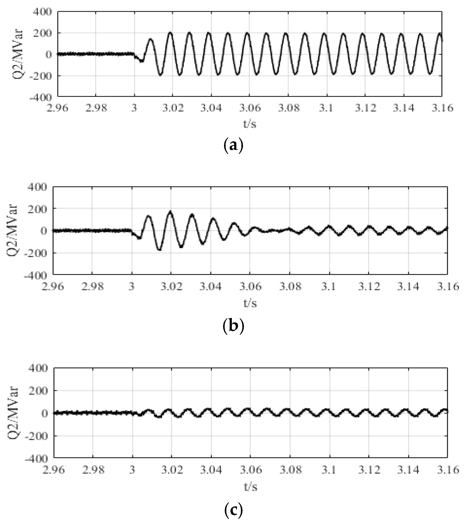
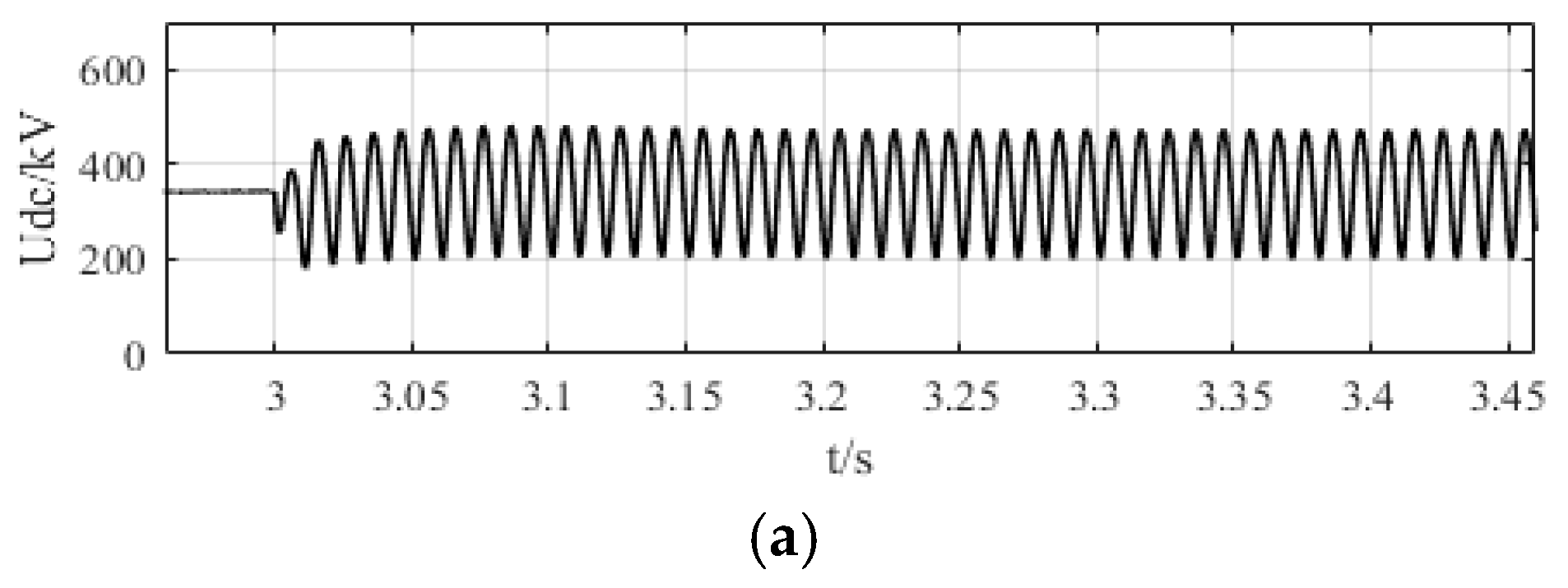
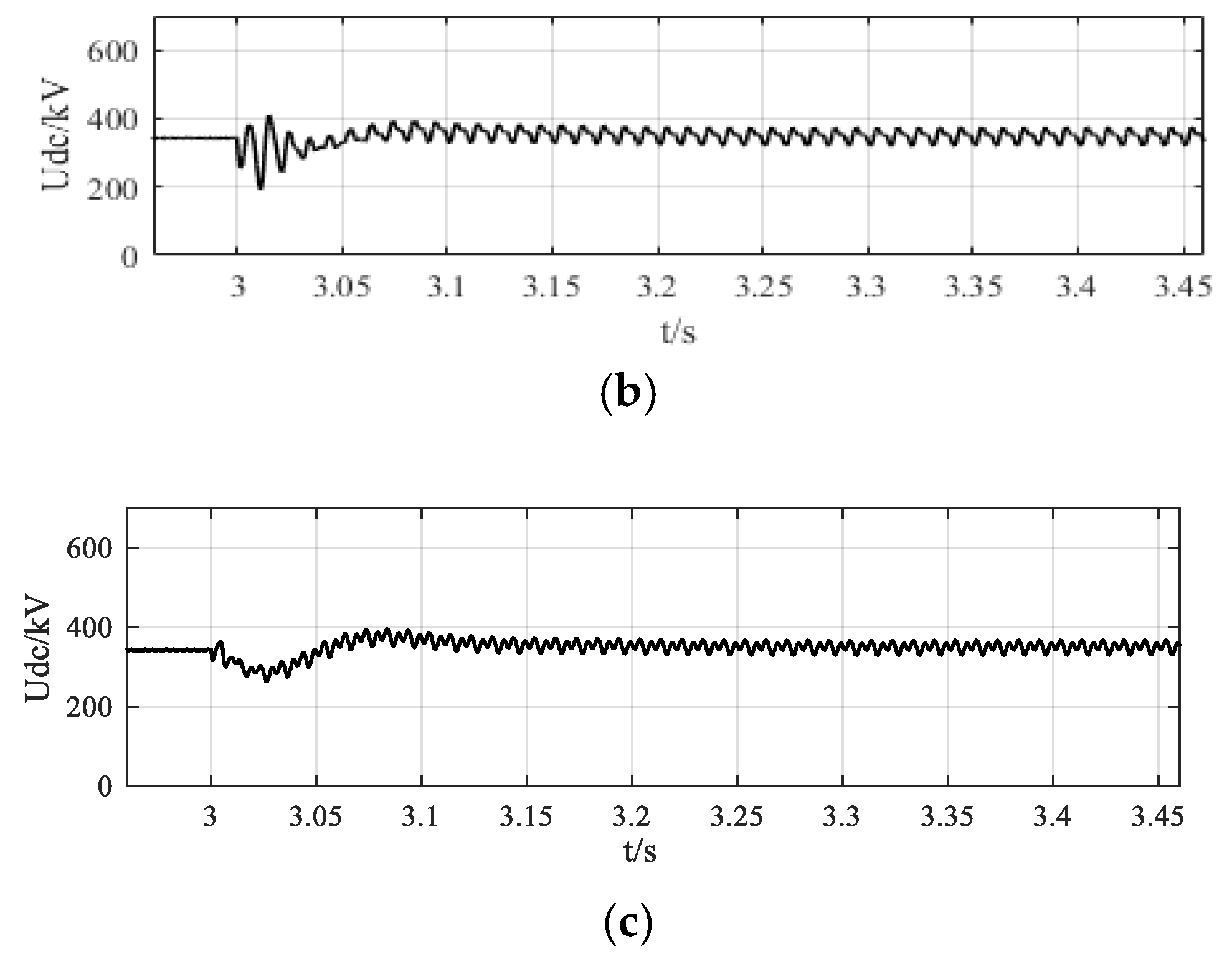
4.3. Case 3
In this case, the situation of single-phase grounding short-circuit fault is tested. Before 3 s, the system operates under normal condition. At time 3 s, the A phase grounding fault with the ground resistance Rg = 0.0005 Ω in AC
2. The simulation results with no auxiliary control, the conventional resonance compensation strategy and the proposed passivity-based compensation strategy via disturbance observer are shown in
Figure 12,
Figure 13 and
Figure 14 respectively.
It is seen that under single-phase grounding short-circuit fault, large amount of double frequency ripples exists in the active and reactive with no auxiliary compensation strategy adopted, which also causes dc voltage fluctuation in double frequency. By comparing the simulation results, it can be found that double frequency ripples in active and reactive power are reduced to a large degree with the proposed compensation strategy and the conventional resonance compensation strategy and the suppression performance with the proposed strategy is relatively better. Additionally, the transient process at time 3 s under the proposed strategy is much improved with no overshoot and fast transient time. The response of dc voltage in
Figure 14 also indicates the satisfactory dynamic performance of the system. Therefore, the proposed control shows superior properties in suppressing the double frequency power ripples and responding to external disturbance.
4.4. Comparable Evaluation
It can be concluded from the above three cases performed on the dc transmission simulation model of
Figure 8 that:
(1) under the proposed control strategy, the double frequency ripples in active and reactive power are regulated with better steady-state suppression performance and enhanced dynamic response compared with the conventional resonance compensation strategy and the only passivity-based compensation strategy;
(2) different passivity parameters and different observer gains have significant impacts on system performance and control effects will be weakened if these parameters are chosen improperly;
(3) in this case of single-phase grounding short-circuit fault, the double frequency ripples in active and reactive power are reduced largely with the proposed control strategy and the transient process can be much improved with little overshoot and fast transient time.
