Article

Damping Optimum-Based Design of Control Strategy Suitable for Battery/Ultracapacitor Electric Vehicles

1
Faculty of Mechanical Engineering and Naval Architecture, University of Zagreb, I. Lučića 5, HR-10000 Zagreb, Croatia
2
Ericsson Nikola Tesla d.d., Krapinska 45, HR-10000 Zagreb, Croatia
3
Faculty of Transport and Traffic Sciences, University of Zagreb, Vukelićeva 4, HR-10000 Zagreb, Croatia
*
Author to whom correspondence should be addressed.
Energies 2018, 11(10), 2854; https://doi.org/10.3390/en11102854
Submission received: 25 September 2018 / Revised: 16 October 2018 / Accepted: 18 October 2018 / Published: 22 October 2018
(This article belongs to the Section D: Energy Storage and Application)

Abstract

:
This contribution outlines the design of electric vehicle direct-current (DC) bus control system supplied by a battery/ultracapacitor hybrid energy storage system, and its coordination with the fully electrified vehicle driveline control system. The control strategy features an upper-level DC bus voltage feedback controller and a direct load compensator for stiff tracking of variable (speed-dependent) voltage target. The inner control level, comprising dedicated battery and ultracapacitor current controllers, is commanded by an intermediate-level control scheme which dynamically distributes the upper-level current command between the ultracapacitor and the battery energy storage systems. The feedback control system is designed and analytical expressions for feedback controller parameters are obtained by using the damping optimum criterion. The proposed methodology is verified by means of simulations and experimentally for different realistic operating regimes, including electric vehicle DC bus load step change, hybrid energy storage system charging/discharging, and electric vehicle driveline subject to New European Driving Cycle (NEDC), Urban Driving Dynamometer Schedule (UDDS), New York Certification Cycle (NYCC) and California Unified Cycle (LA92), as well as for abrupt acceleration/deceleration regimes.

1. Introduction

According to reference [1], road transport significantly contributes to the already alarmingly high levels of CO2 in the atmosphere, which are the main cause of the greenhouse effect [2]. Since this sector is also highly sensitive to the availability of oil [3], it has gradually moved towards greater inclusion of electric vehicles (EVs) into the transportation sector due to their favorable fuel economy and low CO2 footprint during exploitation [1,3]. Moreover, electrical vehicle technology has also been recognized as one of the key factors in the development of intelligent transportation system (ITS) [4], and its integration within the smart grid framework [5].
However, one of the main limitations of currently deployed EVs is that, generally speaking, their batteries can be optimized either for high-power operation or high energy capacity [6,7,8], wherein batteries characterized by high-power operating capabilities would be able to support abrupt loads such as those encountered during vehicle acceleration and regenerative braking regimes, whereas batteries characterized by high energy density can facilitate higher EVs autonomy and larger all-electric driving range [9,10,11]. Additionally, when batteries are subject to frequent high-power abrupt loading regimes, their useful operating life tends to significantly decrease, as opposed to those operating under steady loads [12,13,14]. Under the aforementioned highly dynamic driving conditions, battery thermal stress may become a serious issue, which mandates battery temperature monitoring based on vehicle power-train energy consumption and appropriate battery thermal model [15]. Different battery pack cooling strategies may be employed to prolong the battery useful life and discharge capability (see e.g., [16] and references therein). Both references [15] and [16] emphasize the need for precise overall battery system modeling for thermal monitoring and management.
One way of dealing with the aforementioned battery limitations would be to oversize the EV high-power battery pack [7], but this would in turn increase the EV weight and production costs and would also result in lower efficiency of the electric power-train [14]. A practical alternative to battery over-sizing would be augmentation of the high-energy-density battery with an ultracapacitor-based energy storage system (ESS) [17]. Being characterized by exceptional power densities and cycling abilities (durability) compared to batteries, ultracapacitors represent a viable auxiliary energy storage solution for peak shaving of aforementioned EV pulsed loads [18,19]. Furthermore, a study presented in [20] has suggested that battery hybridization with ultracapacitors within EVs might result in approximately 75% battery cycle life extension through peak load shaving by means of ultracapacitors and associated reduction of battery thermal burden. Moreover, the benefits of employing battery/ultracapacitor hybrid energy storage (HESS) have been confirmed in [21], wherein the cost of temperature-related battery degradation strongly favors the use of ultracapacitors, which would facilitate profitable HESS operation over the anticipated 10-year period of exploitation. Of course, proper sizing of the individual battery and ultracapacitor energy storages within the HESS is needed with respect to the anticipated operating conditions of the EVs [22].
The aforementioned energy storage hybridization concept has shown clear benefits in the transportation sector [23] and has resulted in numerous successful EV applications [9,10,24,25,26]. A parallel battery/ultracapacitor HESS topology with independent load control of individual energy storages should be well suited for energy management control tasks [6,7,11,26,27]. In such an arrangement, both the battery and the ultracapacitor system are equipped with high-performance current-controlled power converters [28], providing bidirectional energy management within the EVs through the common direct-current (DC) bus (see Figure 1). This may be a challenging control problem because the supervisory control strategy should simultaneously keep the DC bus voltage within narrow bounds [9,25], while also distributing the DC bus load between the battery and ultracapacitor ESS to facilitate smooth EV power-train operation for a wide range of operating regimes [29,30]. In particular, the power converter coordination (load distribution) in EV applications should be aimed at ultracapacitor taking on the excessive (pulsed) power demand [31] and acting as a transient power load buffer. This may be facilitated through conditioning of the power demanded from the ultracapacitor power converter with respect to the battery by using a rule-based [32] or a proportional load distribution strategy [31]. Naturally, due to low energy density of ultracapacitor ESS, ultracapacitor system voltage should also be monitored and controlled to avoid overcharging or operation at low state of charge [28].
Simultaneous load sharing and DC bus voltage control typically requires an additional control level. In the case of off-line optimization studies of battery/ultracapacitor HESS, a dynamic programming-based off-line control law may achieve a global optimum in terms of minimum battery degradation over time [21]. This approach, however, cannot be used in real-time applications due to its non-causality (i.e., the requirement to know the driving cycle beforehand), and its intense computational burden. Other optimization-based approaches, such as those based on pseudo-spectral method [33] have also been investigated, wherein the battery cycle life and energy capacity retention optimization problem is solved by using nonlinear programming (NLP). For on-line applications, the aforementioned load allocation problem may be addressed within the framework of robust state control in the form of linear quadratic regulator (LQR) [9] with the EV power-train load treated as a system uncertainty. Successful application of a model predictive controller (MPC) for the energy management task has been demonstrated for the case of fully deterministic process model [34], and stochastic process model representation within MPC framework [12]. The predictive control approach has also been used to minimize the battery and ultracapacitor losses, while simultaneously maintaining the ultracapacitor state of charge within prescribed bounds [35]. Artificial intelligence control methods, such as those based on artificial neural networks (ANNs) [36] and fuzzy logic [37] have also been successful in achieving favorable battery performance indices in terms of battery life extension and capacity preservation within EVs based on HESS. However, these control approaches may be characterized by a rather high level of design complexity and intricate implementation requiring sophisticated control hardware [9,34], which may not be suitable for industry applications. Moreover, in the aforementioned cases of MPC and LQR controllers, the power converter response dynamics and limits are dealt with implicitly through cost function weighting, which might entail some closed-loop performance trade-offs related to weighting factors choices. Therefore, it would be favorable from the standpoint of practical control system design to provide a simple and robust power sharing strategy which would prioritize the power demand to avoid abrupt battery loading issues [38].
Having this in mind, the engineering practice suggests that the prospective control strategy should be characterized by:
(1)
Top-down cascade control system structure, to facilitate direct saturation of current demands via power converter references [39];
(2)
Bottom-up control system design wherein the current control systems for the battery and ultracapacitor ESS are designed and tested first, which is then followed by the comprehensive design of the superimposed feedback control levels [40];
(3)
A direct or indirect load compensator should augment the feedback controllers to deal with potentially abrupt loads at the EV DC bus side [41,42];
(4)
Variable DC bus voltage target, which is characteristic for hybrid-EVs [43,44] and those with fully electrified power-trains [45], and may also be beneficial to useful life extension of capacitors within the inverter DC bus [46];
(5)
Use of control system design methodology which could facilitate straightforward tuning of the closed-loop control system response dynamics;
(6)
Simplicity of code implementation that would enable use on robust microcontroller platforms suitable for automotive applications.
Having this in mind, the hypothesis of this work is that favorable performance of DC bus control system in terms of load suppression can be achieved by using a DC bus cascade control system structure and feed-forward load compensating action (see e.g., [39]), both for the case of constant and variable (EV-operating regime-dependent) DC bus voltage target. The proposed solution is based on the well-established proportional-integral (PI) feedback controller of DC bus voltage augmented with direct load compensator, which command suitable current demands to the hybrid battery/ultracapacitor HESS via a dynamic load distribution scheme. A damping optimum-based methodology [47] is used for feedback control system design, whereas direct zero-pole canceling approach is used for load compensator tuning. The proposed design approach has been verified through simulations and experimentally for different realistic EV power-train operating scenarios. These included a DC bus load step disturbance, EV driveline subject to urban-type driving cycles, such as the New European Driving Cycle (NEDC), Urban Driving Dynamometer Schedule (UDDS), New York Certification Cycle (NYCC) and California Unified Cycle (also known as LA92 cycle) [48] and abrupt EV acceleration and deceleration commands.
The paper is organized in six sections. Section 2 presents the DC bus system and vehicle driveline load model, whereas Section 3 outlines the control system design. Simulation results are included in Section 4, while Section 5 presents the result of experimental verification on a down-scaled DC bus laboratory setup. Discussion of obtained results and final remarks are given in Section 6.

2. EV Power-Train Model

This section presents the models of EV power-train and the DC bus topology based on parallel-connected battery and ultracapacitor ESS.

2.1. Fully Electric Power-Train Topology

The power-train topology of the EVs analyzed herein is shown in Figure 1. The hypothetical vehicle is equipped with the battery and ultracapacitor ESSs parallel-connected via individual two-quadrant DC/DC power converters [32] to the common DC bus, which also supplies the power converter (inverter) of the alternating current (AC) servo motor which provides wheel traction through the fixed-ratio transmission (gearbox). Even though the electric drive-train should also include a hydraulic braking system, a power dissipation resistor for additional electro-dynamic braking capability, and different electrical auxiliaries, these are omitted from the “idealized” EV power-train representation in Figure 1 to simplify the subsequent analysis. Nevertheless, these systems could be taken into account through an additional load component in the DC bus load current iL.

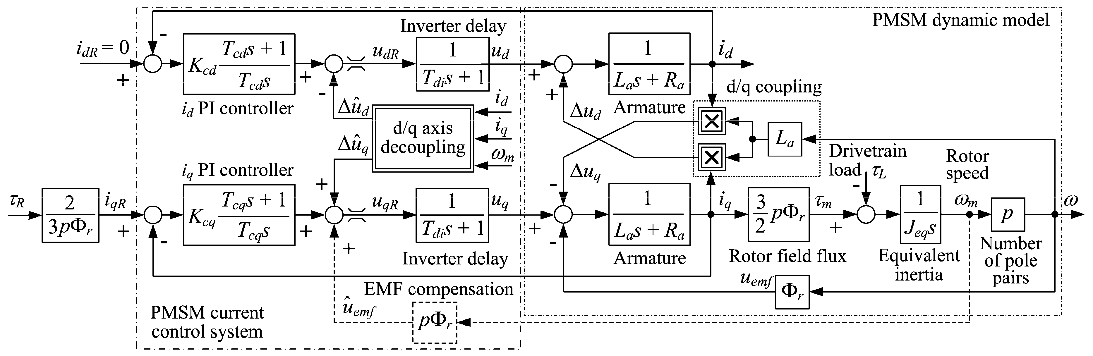
2.2. Traction Motor Control System

An AC permanent-magnet synchronous motor (PMSM) is considered for vehicle traction in this work, primarily due to its advantages over the AC induction motor in terms of higher power density, better overall efficiency, and generally smaller rotor inertia [49]. The natural PMSM machine description in the so-called stationary (stator-side) reference frame is described by a highly nonlinear dynamic model, which is not convenient from the standpoint of control system design. The PMSM control system is realized within the framework of field-oriented (or vector) control, which enables decoupled field flux and torque control at the rotor [39]. For that purpose, the PMSM machine stator-side variables (e.g., phase currents) are transformed into the so-called rotating d-q coordinate frame, where the d-axis relates to the rotor permanent-magnet field flux direction and the q-axis is perpendicular to it. In this way, the PMSM machine model resembles the model of the DC machine which is more convenient for analysis and control system design [39]. The resulting so-called field (d) and torque (q) currents id and iq are obtained from the motor phase sinusoidal currents i1, i2 and i3 by using the well-known Park transform [50]:
[ i d i q ] = 2 3 [ cos ( θ ) cos ( θ 2 π 3 ) cos ( θ 4 π 3 ) sin ( θ ) sin ( θ 2 π 3 ) sin ( θ 4 π 3 ) ] [ i 1 i 2 i 3 ]  
where θ = ωt is the rotor “electrical” angular position, and ω is the rotor “electrical” speed.
Figure 2 shows the block diagram representation of the PMSM current control system in the d-q reference frame. The PMSM servo-machine model comprises the simplified representation of the motor inverter, denoted by a first-order lag term with time constant Tdi corresponding to the small lag of the inverter voltage response. The traction motor model comprises the first-order armature (stator winding) lag model in both the field (d) and torque (q) axis, characterized by armature inductance La and resistance Ra, which determine the respective motor current components based on input voltages ud and uq and the motor electromotive force uemf = Φrω = pΦrωm (ωm is the rotor angular speed, Φr is the rotor field flux, and p is the number of motor pole pairs). The model also includes the so-called cross-axis coupling terms Δud = ωLaiq and Δuq = ωLaid which are the result of the aforementioned Park transform. Dual fast PI controllers are used to control the aforementioned currents id and iq, and their design is presented in the next section. However, to obtain effective suppression of cross-axis coupling terms Δud and Δuq, feed-forward d-q-axis cross-axis compensation terms are also included within the control system in Figure 2. These additive control terms are based on the available motor speed ωm and current signals (see Figure 2). Finally, the current control system in Figure 2 may also include the compensation of counter electromotive force (EMF) (pΦrωm term in Figure 2). The aforementioned PMSM machine parameters which can be used in subsequent simulation analysis can be obtained from the catalogue data for a suitably sized PMSM motor (see Section 4), whereas the current PI controller parameters are obtained as the result of control system design procedure described in Section 3.4 and are listed in Section 4.
The voltage command signals udR and uqR, provided by respective current controllers are then transformed back to the stator-side coordinate frame quantities (i.e., phase voltage references u1R, u2R and u3R) through the inverse Park transform:
[ u 1 R u 2 R u 3 R ] = [ cos ( θ ) sin ( θ ) cos ( θ 2 π / 3 ) sin ( θ 2 π / 3 ) cos ( θ 4 π / 3 ) sin ( θ 4 π / 3 ) ] [ u d R u q R ]  
Operation below the rated speed is considered herein, so current id is kept at zero under closed-loop current control (idR = 0), and the PMSM overall field flux Ψ = Φr + Laid corresponds to the rated rotor flux Φr. In that case the relationship between torque current reference iqR and the motor torque target τR simplifies to (see iqR reference path in Figure 2):
i q R = τ R k T = 2 3 p Φ r τ R  
with kT = 1.5pΦr being the motor torque constant.

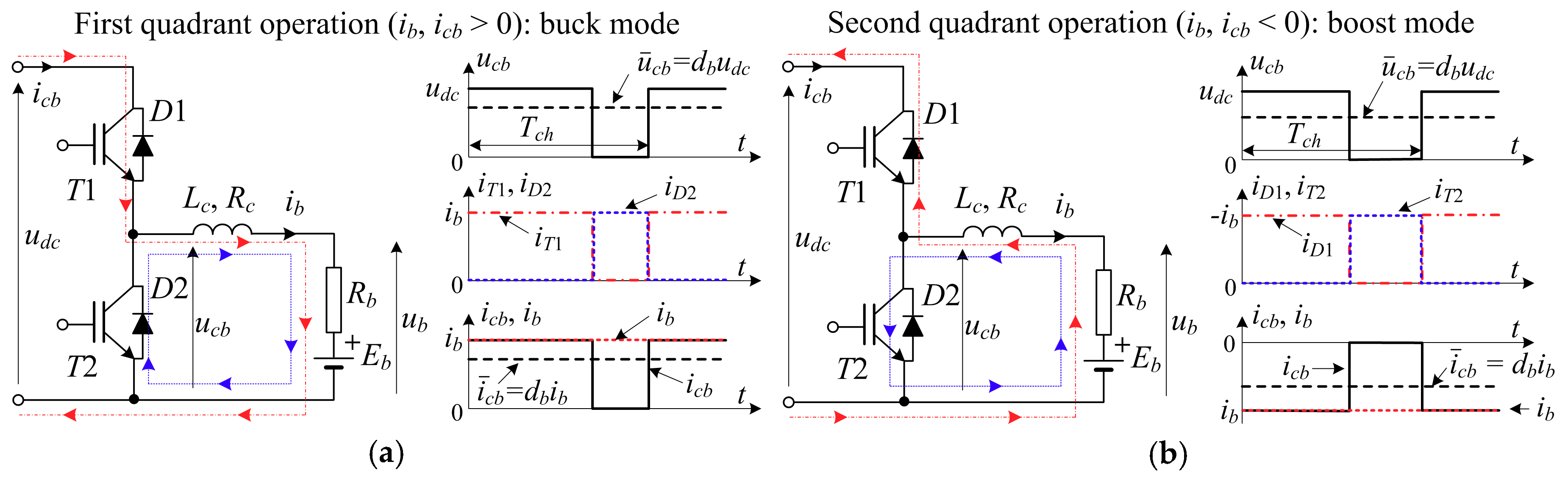
2.3. Dynamic Model of DC Bus
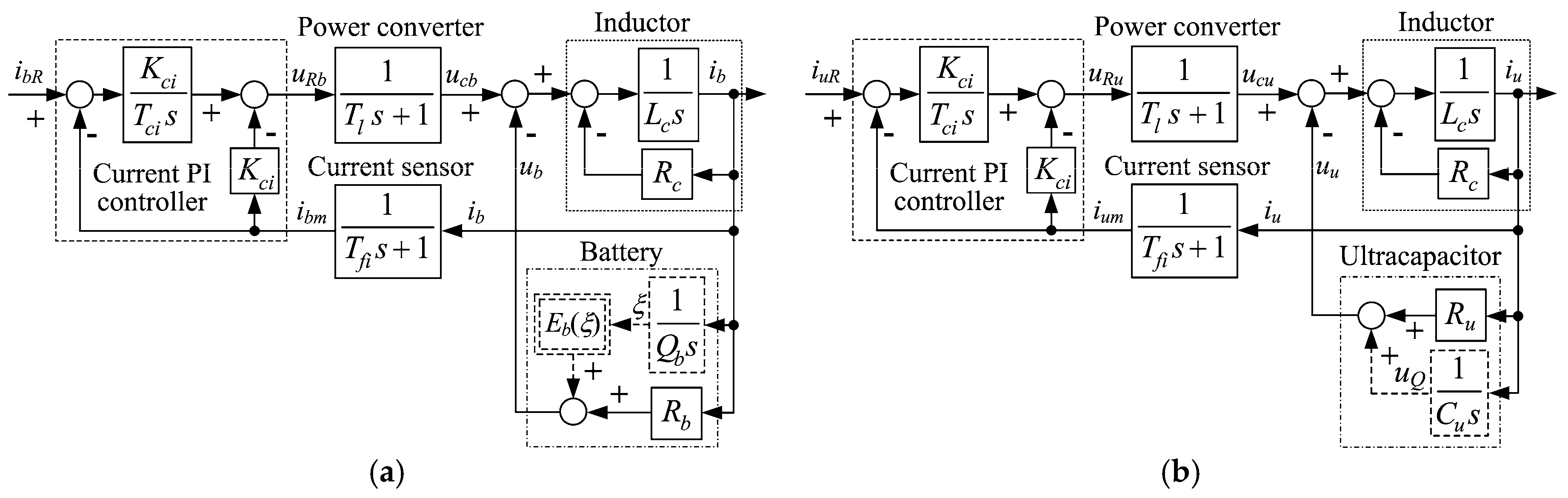
The DC bus system in Figure 1 is described by the following integral-type process model:
u d c = 1 C d c ( i c b + i c u + i L ) d t  
where Cdc represents the capacitance of the DC bus, udc is the voltage across the DC bus, iL represents the EV power-train-related load current, and icb and icu are input currents of battery and ultracapacitor ESS, i.e., input currents of their respective DC/DC power converters.
If battery and ultracapacitor-side current measurements ib and iu (see Figure 1) are available, DC bus-side currents icb and icu could be estimated based on the following relationships between the average values of battery and ultracapacitor currents ib and iu and the corresponding DC/DC power converter instantaneous input currents icb and icu are valid (Figure 3, see also [51,52]):
i ¯ c b = d b i ¯ b i ¯ c u = d u i ¯ u
where db and du are battery and ultracapacitor DC/DC converter pulse-width-modulated (PWM) output voltage duty cycles, respectively, which are readily available from the current controller-based voltage reference commanded to power converter [40]. Since the voltage PWM switching frequency is relatively high, the above averaged currents may be used instead of their instantaneous values within the DC bus model (4). In this way, the subsequent design of the DC bus control system can be greatly simplified [41].
The following expression is valid for the averaged DC bus load iL due to the operation of three-phase motor inverter [46]:
i ¯ L = 3 2 U p h u d c I p h cos φ  
where Iph is the amplitude of the phase current fundamental component, Uph is the amplitude of inverter phase voltage fundamental component, and cosφ is the traction motor power factor.
The principal components of the PMSM stator reference frame currents are given as follows:
[ i 1 i 2 i 3 ] = I p h [ sin ( θ + φ ) sin ( θ 2 π / 3 + φ ) sin ( θ 4 π / 3 + φ ) ]  
These can be transformed to the d-q coordinate frame according to (1), yielding the following relationships between id and iq and the inverter reactive and active current:
[ i d i q ] = [ I p h sin φ I p h cos φ ]  
Finally, by using the d-q frame voltage references udR and uqR obtained from respective current controllers (Figure 2), the amplitude Uph of the inverter phase voltage can be directly calculated in the following manner [42]:
U p h = u d R 2 + u q R 2  
Hence, the DC bus load iL according to Equation (6) can be directly estimated based on Equations (8) and (9), and direct load compensation can be easily facilitated.

2.4. ESS Models

As illustrated by the principal schematic in Figure 1, the battery ESS can be described by the quasi-static Thevenin process model [7]:
u b = i b R b + E b ( ξ )  
ξ = 1 Q b i b d t  
where ub is the battery terminal voltage, ib is the battery current, Rb is the battery equivalent series resistance, Qb is the battery charge capacity, and Eb and ξ are battery electromotive force and state of charge, respectively.
Similarly, ultracapacitor ESS in Figure 1 is modeled as a simple series connection of the equivalent series resistance Ru and ultracapacitor capacitance Cu [7]:
u u = i u R u + 1 C u i u d t  
where uu and iu are the ultracapacitor terminal voltage and input current, respectively.

3. Control System Design

Based on the previously described models of individual EV power-train subsystems, a suitable energy management control strategy is designed in this section.

3.1. Damping Optimum Criterion

Damping optimum criterion [47] is a practical pole-placement-like method of design of linear continuous-time closed-loop systems and is used herein for the tuning of feedback control loops. The tuning procedure is based on the following closed-loop characteristic polynomial:
A c ( s ) = D 2 n 1 D 3 n 2 D n T e n s n + + D 2 T e 2 s 2 + T e s + 1  
where Te represents the so-called closed-loop equivalent time constant, and D2, D3, …, Dn represent the damping optimum characteristic ratios of the nth order closed-loop system.
In the so-called “optimal” case, characterized by Di = 0.5 (i = 2, …, n), the closed-loop system has a quasi-aperiodic step response characterized by an overshoot of approximately 6% (resembling a second-order system with damping ratio ζ = 0.71) and the approximate rise time (1.8–2.1)Te. The aforementioned closed-loop damping ratio value 0.71 is considered an “optimal” choice in practical applications because it provides relatively fast step reference response with small (negligible) overshoot without any weakly damped oscillations in the control loop state variables during the response settling stage. The closed-loop damping adjustment corresponds to the adjustment of the individual characteristic ratios Di, wherein the most dominant characteristic ratio D2 determines the damping of the dominant closed-loop dynamics. In particular, by increasing the characteristic ratio D2 above the optimal value 0.5 (while keeping the less-dominant characteristic ratios at optimal values Di = 0.5, i = 3, …, n), the closed-loop response becomes faster and more oscillatory. On the other hand, by decreasing D2 below 0.5, the closed-loop system damping level is increased, and the closed-loop system is characterized by slower response without overshoot, i.e., the so-called aperiodic dynamics are obtained (see e.g., discussions in [47,53]). Finally, by choosing a larger value of equivalent closed-loop time constant Te, the control system generally tends to be more robust and its sensitivity to noise is greatly improved (i.e., bandwidth ΩBW is proportional to 1/Te). However, this results in control system response slowdown and poorer disturbance rejection performance.

3.2. Low-Level Control of ESSs

Block diagram models of current control loops for the battery and ultracapacitor ESS are shown in Figure 4a,b, respectively. The battery and ultracapacitor energy storages are characterized by their respective equivalent electrical-circuit models given by Equations (10) and (11) in the case of battery, and Equation (12) in the case of ultracapacitor. Individual ESS current control is based on the PI controller in its modified form characterized by the proportional gain being in the local feedback path, while the integral term acts upon the current control error. In this way, controller zeros do not occur in the closed-loop transfer function model between the reference and the controlled variable (see discussion in [53]).
Since charge accumulation processes are typically slow, the battery electromotive force and ultracapacitor charge-related voltage variations are rather non-emphasized compared to voltage variations due to voltage drop across the series resistance, especially during transients. Thus, the dominant current transient dynamics may be expressed by a simple equivalent first-order transfer function model [40]:
G c ( s ) = i b ( u ) ( s ) u c b ( c u ) ( s ) = R t o t 1 ( R t o t 1 L c ) s + 1 ,
where Lc is the inductance of the embedded inductor within the DC/DC power converter and Rtot is the total series resistance of the respective ESS in Figure 4 (Rtot = Rc + Rb in the case of battery and Rtot = Rc + Ru for the case of ultracapacitor).
Based on block diagram representations of battery and ultracapacitor ESS current control loops, the damping optimum-based control system design is carried out. To simplify the design procedure, the small delay due to power converter and current sensor (filter) lags are lumped into a single equivalent lag action:
G p a r ( s ) = 1 T Σ i s + 1  
wherein the equivalent parasitic lag constant Ti = Tl + Tfi may also include the sampling delay if a discrete-time (digital) controller is considered.
Based on Equation (15) and current vs. voltage model (14) under the assumption of slow charge accumulation-related phenomena, the current measurement vs. reference value transfer function model im(s)/iR(s) of both closed-loop current control systems in Figure 4 is given by:
G c i ( s ) = 1 T Σ i L c T c i s 3 K c i + ( R t o t T Σ i + L c ) T c i s 2 K c i + ( R t o t + K c i ) T c i s K c i + 1  
The damping optimum tuning procedure for the current control system is carried out by equating the coefficients of the denominator of the transfer function model (16) with the coefficients of the damping optimum characteristic polynomial defined by Equation (13) for the case of third-order nominal model (n = 3). After some manipulation and rearranging, the following analytical relationships are obtained, which relate the PI controller parameters with the process parameters and damping optimum tuning parameters (i.e., characteristic ratios) [40,41,42]:
T e T e , m i n = 1 D 2 i D 3 i T Σ i 1 + T Σ i R t o t / L c  
T c i = T e ( 1 D 2 i T e T Σ i + L c / R t o t )  
K c i = R t o t ( T Σ i + L c / R t o t D 2 i T e 1 )  
Clearly, this tuning approach enables independent tuning of the response speed (equivalent time constant Tei) and closed-loop damping (dominant characteristic ratio D2i).
Unlike the battery, the ultracapacitor is characterized by rather low energy density (charge capacity). Hence, it may relatively quickly become discharged if frequent discharging demands are commanded to ultracapacitor ESS. Therefore, a supplementary controller of ultracapacitor state of charge is also needed [40,41]. For the sake of simplicity, it can be realized as ultracapacitor terminal voltage PI controller, as shown in Figure 5.
Again, to simplify the design procedure, the rather small time constants of the inner current control loop (Teu) and voltage measurement (Tfv) are lumped into a single equivalent time constant Tu = Teu + Tfv, which results in the following form of the closed-loop system characteristic polynomial:
A c ( s ) = C u T Σ u T I K R 1 s 3 + ( K R 1 + R u C u T I ) s 2 + ( R u C u + T I ) s + 1  
The previously described damping optimum design yields the following analytical expressions for the controller parameters (i.e., time constant Tca and gain Kca):
T c a = T e a R u C u  
K c a = C u ( T e a R u C u ) D 2 a T e a 2 R u C u ( T e a R u C u )  
with the equivalent time constant Tea in above expressions obtained through solving of the following cubic equation:
T e a 3 T Σ u T e a 2 D 2 a D 3 a + R u C u T Σ u T e a D 2 a 2 D 3 a R u 2 C u 2 T Σ u D 2 a 2 D 3 a = 0  
whose solution also needs to satisfy the following feasibility condition to obtain non-negative values of controller parameters:
T e a > R u C u  
Please note that the auxiliary state of charge control loop response dynamics need to be much slower than the command from the superimposed control level (see next subsection), so that any interference with the control action iuR from the upper-level DC bus control strategy (also shown in Figure 5) may be effectively avoided.

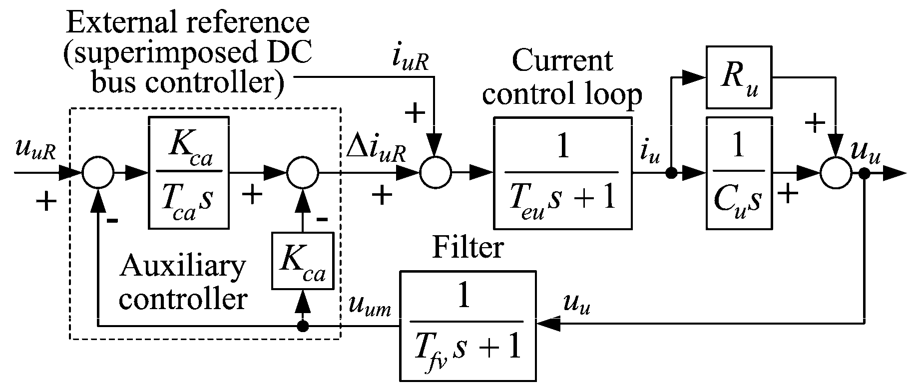
3.3. Design of DC Bus Voltage Control System

Figure 6 shows the DC bus control system arrangement, comprising the upper-level DC voltage feedback controller and feed-forward load compensator which command the inner current control loops of the battery and ultracapacitor ESS through the dynamic load distribution scheme.
The DC bus voltage reference udcR is calculated based on PMSM inverter phase voltage amplitude estimate according to Equation (9), subject to the following constraint related to the upper bound of the phase voltage modulation index Mmax = 1.155 to avoid traction motor phase voltage over-modulation issues [46]:
2 U p h / u d c < M m a x  
This is done in Figure 6 by simply augmenting the theoretical DC voltage result udc = 2Uph/Mmax according to (25) through a voltage scaling factor κu > 1. Note also that the DC bus voltage reference udcR needs to be limited to prevent: (1) DC bus under-voltages and (2) rather inefficient boost operation of the DC/DC power converter at high DC bus voltages (see [54]).
According to Figure 6, the current reference from the upper-level DC bus PI feedback controller and load compensator should be dynamically distributed between the battery and ultracapacitor ESS to facilitate effective load disturbance suppression of the closed-loop system. Since batteries are typically intended for steady and slowly changing loads [55], the battery ESS current controller should be tuned for slow response (i.e., tuned with large equivalent time constant Teb). On the other hand, ultracapacitor ESS, being able to provide peak shaving capability, should be equipped with fast-current controller (i.e., characterized by small equivalent lag Teu). Indeed, within the load distribution strategy in Figure 6 the “slow” battery ESS receives the upper-level command directly, and any abrupt power demand that the battery ESS cannot immediately provide due to its bandwidth limitations is forwarded to the ultracapacitor ESS whose current reference is calculated as icuR = icbRicb. Note that these current commands (icbR and icuR) need to be referred to the battery-side and ultracapacitor-side currents through scaling with respect to individual DC/DC power converter duty cycles as explained in Section 2.3 and elaborated in detail in [41].
The dynamic model of the current reference distribution scheme in Figure 6 is given by the following transfer function:
G i d c ( s ) = i c ( s ) i R ( s ) = 1 T e b s + 1 + ( 1 1 T e b s + 1 ) 1 T e u s + 1  
If the ultracapacitor ESS is characterized by much faster response (Teu << Teb), the above relationship can be simplified as follows [41]:
G i d c ( s ) 1 T e u s + 1  
i.e., the transient dynamics of current supplied to the DC bus are only due to the fast ultracapacitor ESS action characterized by a small lag Teu. For voltage feedback control system design, this relatively small lag may be augmented with the small lag T corresponding to voltage measurement and sampling effect in the case of digital controller.
Based on the above analysis, the DC bus feedback control system transfer function model reads as follows:
G u d c ( s ) = u d c m ( s ) u d c R ( s ) = 1 C d c ( T Σ + T e u ) T d c K d c s 3 + C d c T d c K d c s 2 + T d c s + 1  
which yields the following expressions for PI controller parameters:
T d c = T e d c = T Σ + T e u D 2 d c D 3 d c  
K d c = C d c D 2 d c T e d c  
The feed-forward compensator design is aimed at canceling out the dominant lag in the path of the current reference, which yields the result for the compensator lead time constant [42]:
T F F = T e u  
while the filtering time constant Tf is tuned to achieve a good trade-off between direct compensator response speed and noise attenuation:
T f = α T F F  
with the scaling factor α = 0.2 chosen herein.

3.4. Traction Motor Current/Torque Control

It is assumed that traction motor electromotive force uemf = pΦrωm is compensated for and that the compensation of voltage cross-coupling terms Δud = Laiqm and Δuq = Laidm is also included (see Figure 2). In that case the feedback controller design should be the same for both axes of the rotating d-q coordinate frame, because of their symmetrical structures. Typically, in the case of current control loop design the armature time constant Ta = La/Ra is canceled out by the current PI controller zero (see [39]):
T c d = T c q = T a  
In that case the closed-loop transfer functions of d-q current control systems read as follows:
G c i ( s ) = i d ( q ) ( s ) i d R ( q R ) ( s ) = 1 1 + R a T c d ( c q ) K c d ( c q ) s + T d i T c d ( c q ) K c d ( c q ) s 2  
The damping optimum-based design (with n = 2 in Equation (13)), results in the following expressions for the current controller proportional gains Kcd and Kcq and the current control loop equivalent time constant Tei:
T e i = T d i D 2 i  
K c d = K c q = D 2 i T a T d i R a  

4. Results of Simulation Analysis

The presented control system design has been verified first by means of comprehensive simulation analysis for different scenarios. These included a DC bus load step disturbance and related ESS charging and discharging operation, EV driveline subject to urban-type driving cycles such as NEDC, UDDS, NYCC and California Unified Cycle (also known as LA92 cycle), and abrupt EV acceleration and deceleration commands. The overall EVs simulation model and all sub-models and control systems are implemented within MATLAB/Simulink software environment by using standard blocks and libraries.

4.1. Simulation Model Parameterization

The simulation model comprising the hybrid battery/ultracapacitor energy storage equipped with the previously designed DC bus control system and the traction motor drive within the hypothetical EVs is parameterized based on realistic power-train component data obtained from [43,56,57,58,59].
In addition, for the case of simulation verification based on standard certification driving cycles and abrupt acceleration and deceleration scenarios, it is assumed that vehicle deceleration is predominantly due to traction machine inverter regenerative braking operation. For these scenarios, the traction motor torque reference can be obtained by using a vehicle inertia model extended with rolling resistance and air drag terms, and whose speed is controlled by means of a virtual driver model [60] implemented in the form of a PI controller, as illustrated in Figure 7. The virtual driver PI controller parameters are also determined according to damping optimum, with the assumption that power-train load due to air drag is treated as a slow external disturbance within the vehicle model:
T d r = T d + T e i D 2 d r D 3 d r  
K d r = J e q D 2 d r T d r r w = i g 2 [ J m + 2 J w / i g 2 + m v ( r w / i g ) 2 ] D 2 d r T d r r w  
where Jeq is the equivalent inertia referred to the PMSM traction machine output shaft, ig is the transmission gearbox ratio, rw is the wheel radius, and characteristic ratios D2dr = D3dr = 0.5 are chosen to obtain fast and well-damped closed-loop response.
The resulting parameters of the process models and respective controllers are listed in Table 1, whereas Table 2 lists the parameters of the hypothetic EVs and the virtual driver, the parameters of a suitable traction motor (PMSM) characterized by the rated power of 72 kW (see [58]), and the parameters of the corresponding traction motor current/torque control system. Moreover, the battery and ultracapacitor ESS can be sized based on analyzing the catalogue data from [56,57]. The resulting analysis has shown that the prospective battery with rated capacity of 32 kWh would be characterized by the mass of 320 kg, and the length of 1.4 m, and would measure 0.73 m in width and 0.22 m in height, thus yielding the total volume of 0.22 m3. Similar analysis has yielded the dimensions of ultracapacitor ESS to be 1.29 m in length, 0.62 m in width and 0.22 m in height, thus yielding the overall ultracapacitor ESS volume of 0.22 m3, and weight of about 180 kg.

4.2. Verification of HESS and DC Bus Control System

The comparative simulation responses of the low-level current control loops within ultracapacitor and battery ESS are shown in Figure 8 for the stepwise discharging command with current reference step magnitude of −10 A. The ultracapacitor current control system is tuned for a fast and well-damped step response according to the damping optimum procedure, resulting in the closed-loop equivalent time constant Teu = 15 ms (Table 1), which yields the response settling time of about 30 ms with less than 6% step response overshoot (Figure 8a). The response speed (bandwidth) of the ultracapacitor current control loop can be arbitrarily slowed down by means of increasing the closed-loop equivalent time constant Teu according to Equation (17). Figure 8a further shows that decreasing the most dominant characteristic ratio D2i below the optimal value (0.5) results in Teu increase, as well as in increased damping of the closed-loop system. In the case of battery ESS (Figure 8b), two distinctive PI controller tuning cases have been considered with respect to the closed-loop equivalent time constant Teb choices (Figure 8b). Namely, the battery ESS control system can be tuned for rather fast response characterized by favorable response damping (Teb = 20 ms in Figure 8b). However, a more conservative tuning aimed at slower closed response should be preferred because the battery ESS is intended for slowly varying loads. The comparative simulation responses obtained for the “slower” PI controller tuning (with Teb = 200 ms) in Figure 8b, indeed show a ten-fold longer closed-loop transient settling time with respect to “fast” controller tuning.
Figure 9 shows the comparative simulation responses of the DC bus control system subject to load current step with the magnitude of 50 A, effectively emulating a sudden 18 kW driveline acceleration command (25% of the traction motor rated power). When PI feedback controller alone is used (Figure 9a), the DC bus voltage is characterized by well-damped dynamic behavior. However, the stepwise disturbance response is characterized by a relatively large voltage drop of 8.9% with respect to the selected DC bus voltage target udcR = 360 V, with the voltage response settling to the target value within 140 ms due to non-negligible lag the feedback loop characterized by the equivalent time constant Tedc = 80 ms (top trace in Figure 9a). The HESS responses (bottom plot in Figure 9a) confirm that the ultracapacitor ESS reacts notably faster compared to the battery ESS within the proposed dynamic load distribution scheme. When the PI controller is augmented by the direct feed-forward compensator (Figure 9b), the DC bus voltage drop after the stepwise load is reduced to 1.7% of the DC bus voltage target due to the fast reaction of the feed-forward compensator, which directly forwards a rather fast-current command to the intermediate-level load distribution scheme. As a result, the load suppression potential of the control system featuring the ultracapacitor ESS equipped with fast-current controller is better used, as opposed to the when only the PI feedback controller is used (see Figure 9a,b).
Figure 10 illustrates the DC bus system behavior for the case when the ultracapacitor ESS is being charged from the common DC bus under the auxiliary ultracapacitor voltage controller, which commands appropriate current command to the ultracapacitor ESS current control system. Since the auxiliary controller output is limited to avoid excessive DC bus loads for the purpose of ultracapacitor ESS voltage control, the ultracapacitor ESS represents a near-constant DC load throughout most of the charging transient, which results in a linear rise of the ultracapacitor terminal voltage towards the target value uuR = 300 V (top plot Figure 10a). The DC bus voltage response is characterized by an initial voltage drop (bottom plot in Figure 10a) corresponding to the ultracapacitor ESS load being demanded by the auxiliary controller (top plot in Figure 10b). As indicated by the battery ESS response (bottom plot in Figure 10b), the required ultracapacitor charging current is provided by the battery ESS, which points out to effective load distribution performed by the intermediate-level control scheme in Figure 6.

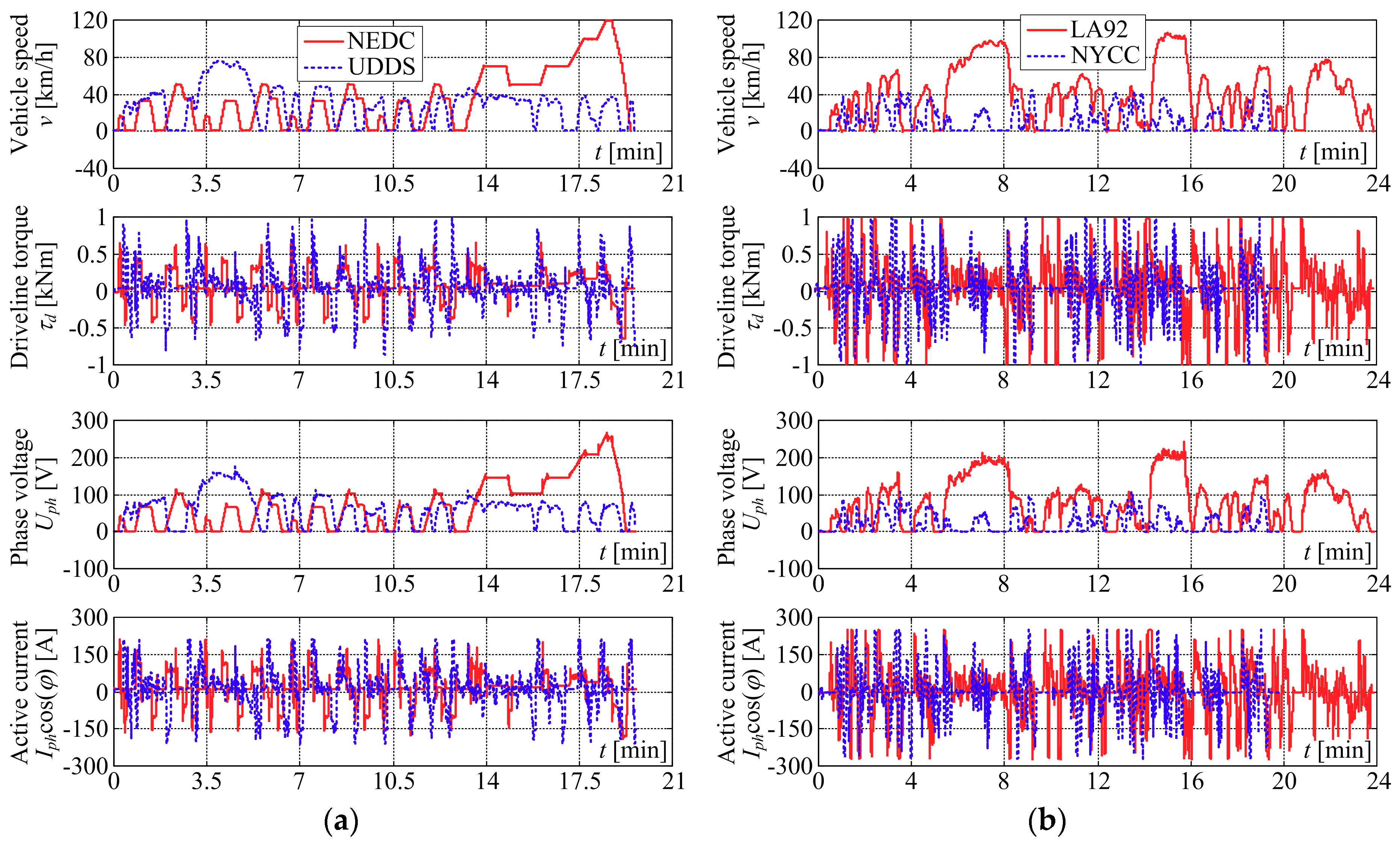
4.3. Driving Cycle-Based Analysis

Figure 11 shows the simulation results of the vehicle model equipped with the virtual driver for the chosen certification driving cycles, i.e., NEDC, UDDS, LA92 and NYCC (see e.g., [15,48]). The driving cycle data are obtained from the US Environmental Protection Agency (EPA) website [48] and have been downloaded as vehicle speed over time traces in ASCII format, and used within the MATLAB/Simulink simulation environment. Since NEDC cycle comprises an interval of urban-like driving (frequent vehicle starting and stopping), followed by a highway-like driving and final rapid deceleration, vehicle driveline is characterized by notable driveline torque τd and vehicle speed v variations. The aforementioned torque variations are even more emphasized for the UDDS cycle (see Figure 11a). Similar result is obtained for the cases of LA92 and NYCC driving cycles, wherein the former combines high-speed and low-speed driving with rather abrupt and frequent vehicle acceleration and deceleration, while the latter is characterized by frequent starting and stopping, albeit at lower vehicle speeds characteristic to congested traffic conditions (Figure 11b). The traction motor phase voltage Uph and active current component Iph·cos(ϕ) traces shown in Figure 11 closely reflect the above vehicle speed and driveline torque profiles.
Figure 12 shows the corresponding load current iL and DC voltage profiles udc for the individual cases of vehicle driveline and traction motor inverter responses in Figure 11. The comparative DC bus voltage responses in Figure 12 indicate that NEDC driving cycle is characterized by a notable DC bus voltage target increase above the lower threshold Umin = 328 V in the final, highway-like driving interval (top plot in Figure 12a). Namely, this increased DC bus voltage is needed to cover for increased traction motor voltage demand corresponding to high motor (and vehicle) speeds characterized by high motor back-EMF values. Similar requirement with respect to DC bus voltage reference is also observed in the case of LA92 cycle when the vehicle speed increases above the 80 km/h (check traces in Figure 11b and Figure 12c). The UDDS and NYCC driving cycles, being characterized by vehicle speeds below 80 km/h, do not mandate DC bus voltage increase above the lower threshold Umin, as indicated by traces in Figure 12b,d. Moreover, all driving cycles are characterized by notably smaller DC bus voltage tracking errors when direct feed-forward compensator is used, as opposed to the case when PI feedback controller has not been augmented by the feed-forward load compensating action. This is also illustrated by DC bus load current tracking error Δic = − (iL + ic) traces in bottom plots in Figure 12a,d, wherein a notable reduction of load current tracking error magnitudes is observed when direct feed-forward compensator is used.
The above conclusions are further strengthened by the comparative DC bus voltage tracking error and load tracking error indices, shown in Figure 13. In particular, when PI controller is used alone, the more dynamic UDDS and LA92 driving cycles are characterized by somewhat larger DC bus voltage tracking errors compared to the case of NEDC, and especially with respect to relatively low-speed NYCC driving cycle (see Figure 13a,b). As expected, introduction of feed-forward load compensator results in notable decrease of DC voltage target tracking error, especially in the case of the highly dynamic UDDS driving cycle. The LA92 driving cycle, on the other hand, is characterized by the least emphasized reduction of maximum voltage tracking error, which is due to two rather dynamic (high-bandwidth) DC bus voltage and load profiles (t between 6.5 s and 8.2 s and t between 14.5 s and 15.7 s in Figure 12c), which relates to higher magnitudes of the maximum DC bus and load current tracking indices in Figure 13a,c. Nevertheless, it may be concluded that in general the feed-forward load compensator, being able to directly react to readily available traction motor torque command (see feed-forward path Figure 6), should be capable of timely commanding precise current demand to the common DC bus, thus improving the anticipated load current tracking ability of the overall control system (as shown in Figure 12 and Figure 13), and to effectively suppress the majority of DC bus voltage excursions in a systematic manner.

4.4. Analysis for EV Constant Acceleration/Deceleration Regime

The proposed DC bus control strategy, with feed-forward load compensator included, has also been tested for the EVs subject to abrupt acceleration and deceleration regimes, and the comparative results are shown in Figure 14. The responses are characterized by abrupt changes of driveline torque followed by quasi-steady-state torque demand during acceleration and deceleration phases (Figure 14a), which apparently represents a kind of a worst-case scenario for the DC bus control strategy. Namely, the aforementioned driveline torque profile results in relatively slow ramp-like profile of DC bus load iL during steady acceleration and deceleration, whereas abrupt DC load changes occur at the vehicle acceleration to deceleration (reversal) point (Figure 14b). Note also that the sudden DC bus voltage drop at reversal from acceleration to deceleration command is needed to facilitate reduced motor phase and DC bus voltage required during transient from driving to regenerative braking. The aforementioned abrupt DC bus load iL transient is, as expected, effectively handled by the ultracapacitor ESS, while the gradual ramp-like DC bus load profiles (during constant acceleration/deceleration) are handled by the battery ESS.

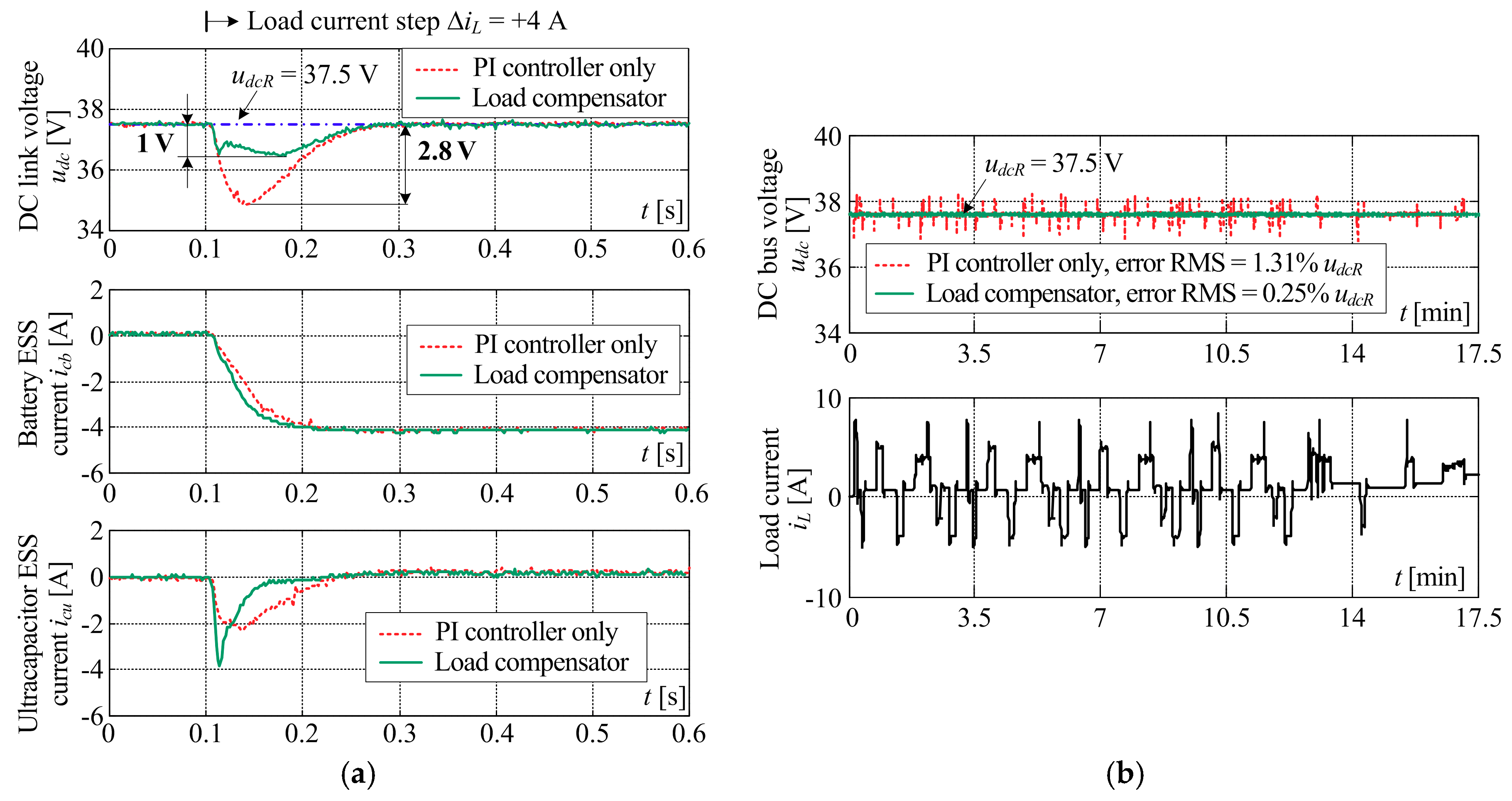
5. Results of Experimental Verification

The core of the DC bus control system has also been verified by means of experiments conducted on the dedicated down-scaled laboratory setup, previously designed and tested in [40,41]. Figure 15 shows the principal schematic of the laboratory setup which can be externally supplied from the AC grid, or can work in the isolated (islanded) mode. Setup comprises three two-quadrant (buck-boost) DC/DC power converters connected in parallel to the common DC bus, wherein two of those power converters are used for power flow control of the battery and ultracapacitor module-based ESS, and the third power converter is used to emulate a passive or active DC bus load by supplying power to the dissipation resistor or an another battery. Due to safety concerns, the safety and diagnostics system implemented within the programmable logic controller (PLC) limits the DC voltage to 45 V, while the under-voltage trip is pre-set to 30 V. Battery and ultracapacitor ESS current control, and DC bus voltage control algorithms are implemented within an inexpensive PLC, whereas the DC bus load control, and data collection and supervision of the laboratory setup is implemented within the National Instruments LabView environment by using a CompactRIO acquisition and control system. The parameters of the down-scaled laboratory setup and the corresponding DC bus control system are listed in Table 3.
The results of experimental verification of the DC bus control system for the case of abrupt (stepwise) DC bus load and load profile corresponding to the NEDC driving cycle are shown in Figure 16a,b, respectively. Due to the aforementioned safety features, the DC bus voltage has been pre-set in both cases in the middle of the usable voltage range (i.e., udcR = 37.5 V is used). For the same reason, the final part of the NEDC certification cycle, corresponding to the final accelerating of the vehicle towards 120 km/h and subsequent abrupt braking have been omitted from the analysis to avoid tripping the over-voltage and under-voltage protections at the laboratory setup.
The comparative results in Figure 16a, obtained for stepwise load current change with the step magnitude of 4 A, indeed show that the proposed control system design results in well-damped and rather fast response of the DC bus control system and the inner current control loops of individual ESSs (i.e., battery and ultracapacitor). As expected, the use of DC bus control system comprising both the PI feedback controller and the direct load compensator results in notably smaller DC bus voltage drop and faster DC bus voltage recovery compared to the case when PI feedback controller is used alone. This is further confirmed by the comparative traces obtained for the case of down-scaled DC bus load corresponding to EV driveline subject to highly dynamic NEDC certification cycle. In particular, the feed-forward compensator-based control system load suppression ability, expressed in terms of DC bus voltage reference tracking root mean squared (RMS) error, is over five-fold improved compared to the case when only PI feedback controller is used. As explained earlier, this is primarily due to the better use of load suppression potential of the ultracapacitor ESS featuring a fast current controller under the fast current demand from the direct feed-forward load compensator.

6. Discussion and Concluding Remarks

This paper has presented the design of EV DC bus control system based on a battery/ultracapacitor HESS, and its coordination with the fully electrified vehicle driveline control system via the readily available traction motor current and voltage variables. The control strategy has included the upper-level DC bus voltage feedback PI controller augmented with a direct load compensator for fast suppression of abrupt DC bus loads, which have commanded appropriate current references to the battery/ultracapacitor HESS via the intermediate-level dynamic load distribution scheme. The feedback control design has been carried out by using the damping optimum criterion. The proposed methodology has been verified by means of simulations for different realistic EV-operating regimes, and experimentally on the down-scaled DC bus laboratory setup. Simulation and experimental results have pointed out to:
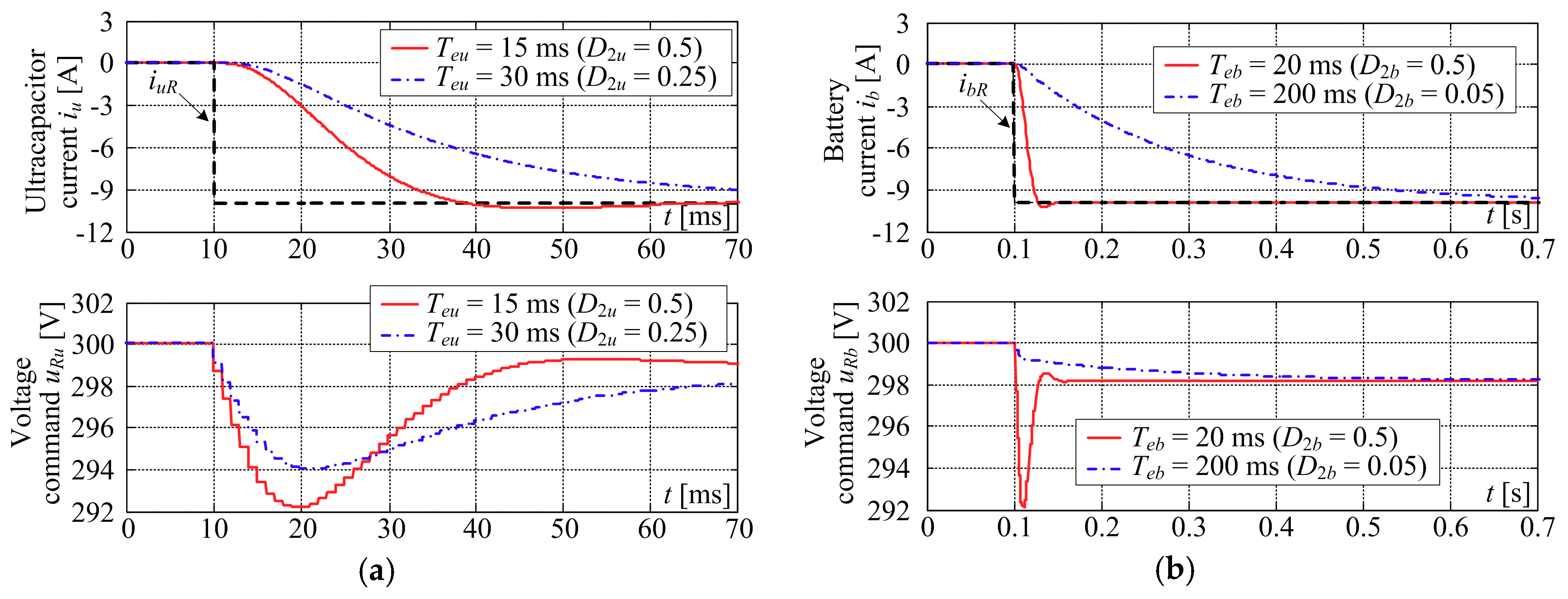
  • Damping optimum tuning approach having been able to ensure well-damped closed-loop behavior of designed feedback systems (i.e., less than 6% step response overshoot). It has also been able to precisely adjust the closed-loop response speed of battery/ultracapacitor HESS inner current control loops via the choice of the closed-loop equivalent time constant. This has enabled rather fast-current reference tracking of the ultracapacitor ESS (30 ms step response settling time has been obtained), while also achieving notably slower battery ESS response (characterized by 400 ms response time) within the DC bus control system.
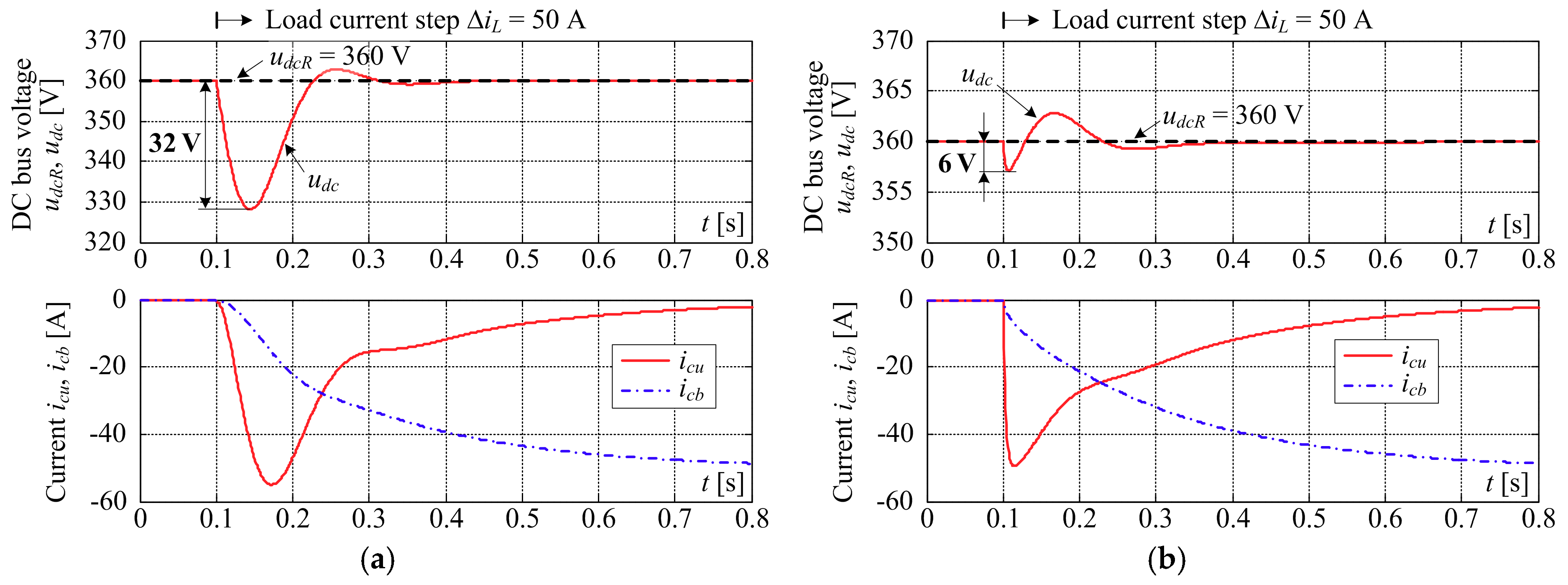
  • The load suppression ability of the overall DC bus control system having been notably improved by the introduction of the direct load compensator, which has typically resulted in three to five times smaller DC bus voltage excursion after an abrupt DC bus load. In particular, for the realistic scenario of 25% stepwise change of EV driveline load, DC voltage excursion is reduced from 8.9% of the target DC bus voltage value in the case of PI feedback controller to 1.7% in the case when PI controller has been augmented by the load compensator based on DC bus load reconstruction from traction motor variables.
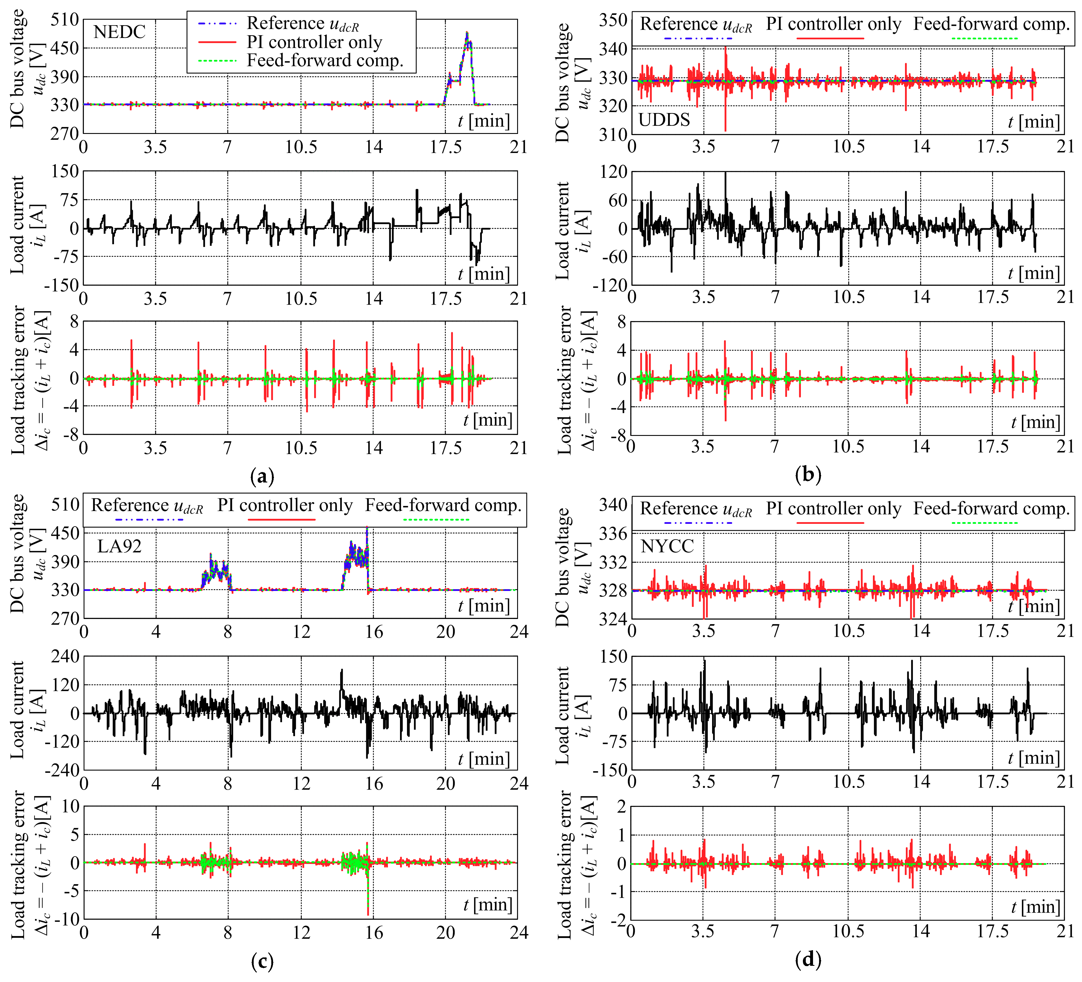
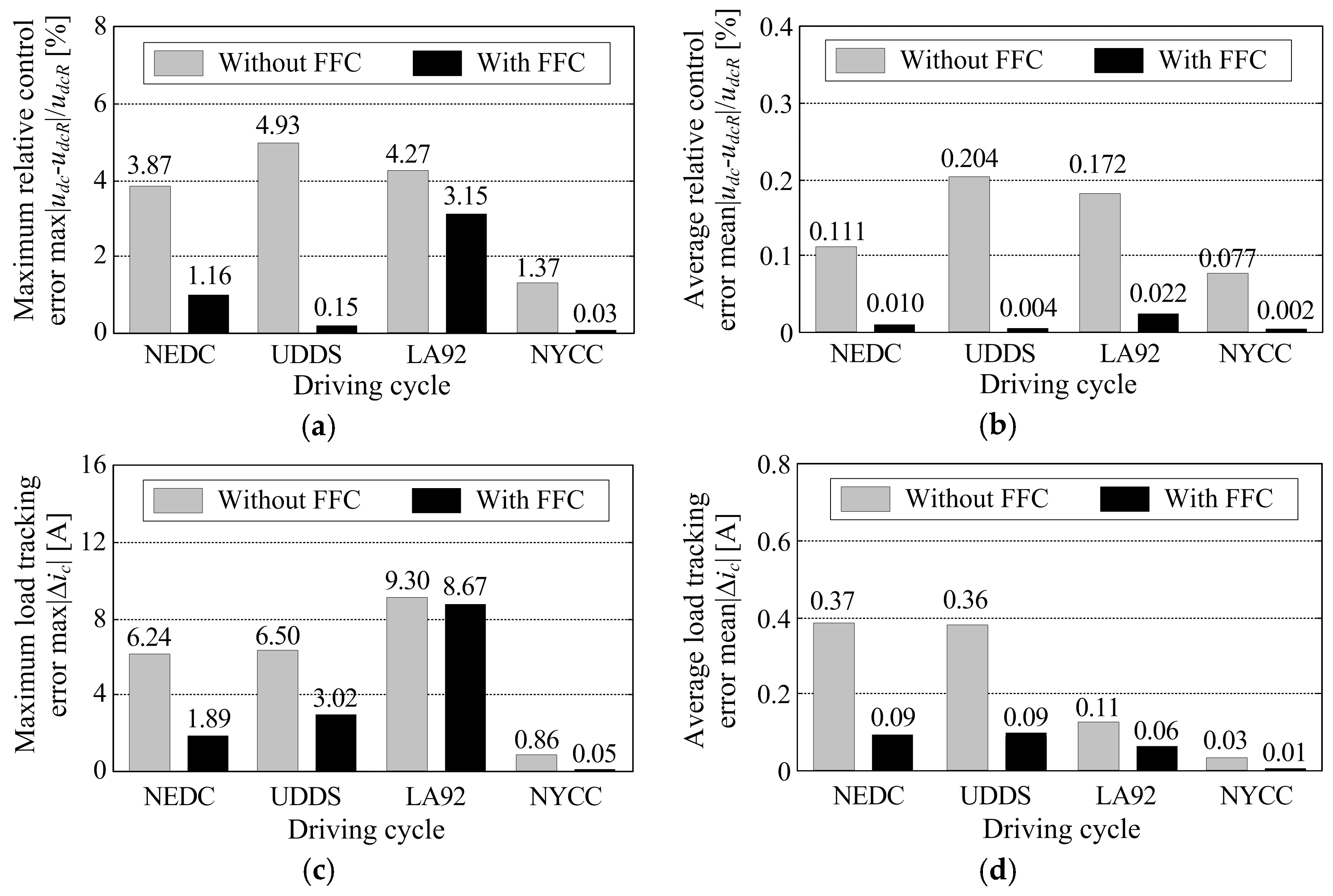
  • The DC bus voltage target tracking performance having benefited from the inclusion of direct feed-forward load compensator for different certification driving cycles and corresponding DC bus voltage profiles calculated from traction motor variables. Namely, use of direct feed-forward load compensator has resulted in the reduction of the maximum DC bus voltage tracking error from 3.87% to 1.16% of the DC voltage target in the case of NEDC driving cycle, and from 4.93% to just 0.15% in the case of UDDS scenario. Similar reduction has also been observed for NYCC driving scenario (i.e., from 1.37% to just 0.03% has been obtained), whereas LA92 driving cycle has been characterized by the DC bus excursion reduction from 4.27% to 3.15%. Generally speaking, the DC bus voltage average tracking error has been reduced between one and two orders of magnitude for all driving cycles when load compensator has been used.
Future research may be directed towards the extension of the proposed control strategy for multiple energy storages, and related applications in renewable energy systems and EVs.

Author Contributions

This manuscript is the result of successful collaboration of all its authors. In particular, D.P., M.C. and M.H. conceived the idea and theoretical development. D.P. and M.H. designed and performed the simulation analysis. Finally, D.P., M.C. and Z.K. wrote the manuscript text and produced all illustrations, while T.J.M. and D.Z. made key contributions during the revision of the manuscript draft and final editing.

Funding

This research was funded by Croatian Science Foundation, through the collaborative project “Optimization of renewable electricity generation systems connected in a microgrid”, grant number 08/40.

Acknowledgments

It gratefully acknowledged that this research has also been supported by the European Regional Development Fund under the grant KK.01.1.1.01.0009 (DATACROSS).

Conflicts of Interest

No conflict of interest exists with respect to funding institutions.

Nomenclature

Abbreviations
ACAlternating current
d-qField-torque rotating reference frame
DCDirect current
DC/DCDC-to-DC (power conversion)
EMFElectromotive force
ESSEnergy storage system
EVElectric vehicle
HESSHybrid energy storage system
LA92California Unified Cycle
NEDCNew European Driving Cycle
NYCCNew York Certification Cycle
PIProportional-integral
PWMPulse-width Modulation
RMSRoot mean squared (error)
UDDSUrban Driving Dynamometer Schedule
Greek Symbols
αFiltering time constant scaling factor
κuDC bus voltage target scaling factor
ρaDensity of air
ΦrRotor permanent-magnet field flux
ΩbwClosed-loop bandwidth
ΔicDC bus load tracking error
ΔiUrUltracapacitor ESS auxiliary controller output
Δud, Δuqd-q frame cross-axis coupling terms
ϕStator current vs. voltage phase angle
θRotor electrical angle
τRTraction motor torque reference
ωRotor electrical speed
ωm, τmTraction motor speed and torque
ωd, τdDriveline speed and torque
ξBattery state of charge
Subscripts
1,2,3PMSM stator quantity
aAuxiliary control loop
bBattery control loop quantity
drVirtual driver
D1, D2Quantity of fly-wheeling diode within DC/DC power converter
diLag (of motor inverter voltage)
eEquivalent (time constant)
iPMSM current control loop
lLag (of power converter voltage)
uUltracapacitor ESS quantity
vVoltage control loop
LLoad
phPhase quantity
rPMSM rotor (field flux)
RReference (target) value
T1, T2Quantity of semiconductor-controlled switch within DC/DC power converter
Lumped quantity
Superscripts
x ^ Estimated value of x
x ¯ Average value of x
Variables
cosϕMotor power factor
db, duBattery and ultracapacitor ESS DC/DC power converter PWM duty cycles
EbBattery electromotive force
ib, iuBattery and ultracapacitor currents
icDC bus input current
icb, icuBattery/ultracapacitor ESS input currents
id, iqDirect (field) and quadrature (torque) currents in the d-q rotating reference frame
idR, iqRField and torque current references
iLDC bus load current
IphStator phase current amplitude
u1,2,3(R)PMSM stator voltages (references)
ucb, ucuBattery and ultracapacitor ESS DC/DC power converter output voltage
udR, uqRDirect and quadrature axis voltage components
udR, uqRDirect and quadrature axis voltage references from PI current controllers
uuRUltracapacitor ESS voltage reference
udcDC bus voltage
uemfAC machine electromotive force
UphStator phase voltage amplitude
vVehicle longitudinal speed
Parameters
CdAir drag coefficient
CdcDC link capacitance
CuUltracapacitor capacitance
D2, …, DnDamping optimum characteristic ratios
gFree fall (gravity) acceleration
igGearbox transmission ratio
Jm, JwMotor and wheel inertia, respectively
JeqEquivalent inertia at PMSM rotor side
kE, kTPMSM electromotive force and torque constants, respectively
Kca, TcaAuxiliary ultracapacitor ESS state-of-charge controller gain and integral time constant
Kcd, KcqPMSM current controller proportional gains
Kci, TciBattery and ultracapacitor ESS current controller gain and integral time constant
Kdc, TdcDC bus controller proportional gain and integral time constant
Kdr, TdrVirtual driver proportional gain and integral time constant
La, RaPMSM armature inductance and resistance
Lc, RcInductor inductance and resistance
RtotOverall series resistance
mvVehicle mass
MmaxMaximum value of modulation index
pPMSM number of pole pairs
rwWheel radius
RoRolling resistance coefficient
TaPMSM armature time constant
Tl, TdiVoltage response delay of DC/DC power converter and motor inverter
TeClosed-loop equivalent time constant
TeaEquivalent time constant of the auxiliary ultracapacitor state-of-charge control loop
TeiEquivalent time constant of the PMSM current control loop
Tcd, TcqPMSM current controller integral time constants
Teb, TeuEquivalent time constants of battery and ultracapacitor current control loops
Tfi, TfvCurrent and voltage measurement (filter) time constants
Tf, TFFFeed-forward load compensator lag time constant and lead time constant
TParasitic time constant of the voltage control loop
TiParasitic time constant of the current control loop
TuParasitic time constant of the auxiliary state-of-charge control loop
UminDC bus voltage lower bound
UmaxDC bus voltage upper bound

References

  1. Saber, A.Y.; Venayagamoorthy, G.K. Plug-in vehicles and renewable energy sources for cost and emission reductions. IEEE Trans. Ind. Electron. 2011, 58, 1229–1238. [Google Scholar] [CrossRef]
  2. Hansen, J.; Sato, M.; Kharecha, P.; Beerling, D.; Berner, R.; Masson-Delmotte, V.; Pagani, M.; Raymo, M.; Royer, D.L.; Zachos, J. Target atmospheric CO2: Where should humanity aim? Open Atmos. Sci. J. 2008, 2, 217–231. [Google Scholar] [CrossRef]
  3. Yong, J.Y.; Ramachandramurty, V.K.; Tan, K.M.; Mithulananthan, N. A review of the state-of-the-art technologies of electric vehicle, its impacts and prospects. Renew. Sustain. Energy Rev. 2015, 49, 365–385. [Google Scholar] [CrossRef]
  4. Barth, M.; Todd, M. Intelligent transportation system architecture for a multi-station shared vehicle system. In Proceedings of the 2000 IEEE Intelligent Transportation Systems Conference, Dearborn, MI, USA, 1–3 October 2000; pp. 240–245. [Google Scholar] [CrossRef]
  5. Un-Noor, F.; Padmanaban, S.; Mihet-Popa, L.; Nurunnabi Mollah, M.; Hossain, E. A comprehensive study of key electric vehicle (ev) components, technologies, challenges, impacts, and future direction of development. Energies 2017, 10, 1217. [Google Scholar] [CrossRef]
  6. Burke, A.; Miller, M.; Zhao, H. Lithium batteries and ultracapacitors alone and in combination in hybrid vehicles: Fuel economy and battery stress reduction advantages. In Proceedings of the 25th World Battery, Hybrid, and Fuel Cell Electric Vehicle Symposium and Exhibition (EVS-25), Shenzhen, China, 5–9 November 2010. [Google Scholar]
  7. Kupperman, A.; Aharon, I. Battery-ultracapacitor hybrids for pulsed current loads: A review. Renew. Sustain. Energy Rev. 2011, 15, 981–992. [Google Scholar] [CrossRef]
  8. International Renewable Energy Agency (IRENA). Road Transport: The Cost of Renewable Solutions. 2013. Available online: http://www.irena.org/Publications/2013/Jul/Road-Transport-the-Cost-of-Renewable-Solutions (accessed on 15 October 2018).
  9. De Castro, R.; Araújo, R.E.; Trovão, J.P.F.; Pereirinha, P.G.; Melo, P. Robust DC-link control in EVS with multiple energy storage systems. IEEE Trans. Veh. Technol. 2012, 61, 3553–3565. [Google Scholar] [CrossRef]
  10. Amjadi, Z.; Williamson, S.S. Power-electronics-based solutions for plug-in hybrid electric vehicle energy storage and management systems. IEEE Trans. Ind. Electr. 2010, 57, 608–616. [Google Scholar] [CrossRef]
  11. Cao, J.; Emadi, A. A new battery/ultracapacitor hybrid energy storage system for electric, hybrid and plug-in hybrid electric vehicles. IEEE Trans. Power Electr. 2012, 27, 122–132. [Google Scholar] [CrossRef]
  12. Laldin, O.; Moshirvaziri, M.; Trescases, O. Predictive algorithm for optimizing power flow in hybrid ultracapacitor/battery storage systems for light electric vehicles. IEEE Trans. Power Electr. 2013, 28, 3882–3895. [Google Scholar] [CrossRef]
  13. Omar, N.; Monem, M.A.; Firouz, Y.; Salmien, J.; Smekens, J.; Hagazy, O.; Gaulous, H.; Mulder, G.; Van den Bossche, P.; Coosemans, T.; et al. Lithium iron phosphate based battery—Assessment of aging parameters and development of life cycle model. Appl. Energy 2014, 113, 1575–1585. [Google Scholar] [CrossRef]
  14. Shiau, C.-S.N.; Kaushal, N.; Hendrickson, C.T.; Paterson, S.B.; Whitacre, J.F.; Michalek, J.M. Optimal plug-in hybrid electric vehicle design and allocation for minimum life cycle cost, petroleum consumption and greenhouse gas emissions. Trans. ASME—J. Mech. Des. 2010, 132, 183–195. [Google Scholar] [CrossRef]
  15. Samadani, E.; Farhad, S.; Panchal, S.; Fraser, R.; Fowler, M. Modeling and Evaluation of Li-ion Battery Performance based on the Electric Vehicle Field Tests. In Proceedings of the SAE 2014 World Congress & Exhibition, Detroit, MI, USA, 8–10 April 2014. [Google Scholar] [CrossRef]
  16. Patil, M.; Panchal, S.; Kim, N.; Lee, M.Y. Cooling Performance characteristics of 20 Ah lithium-ion pouch cell with cold plates along both surfaces. Energies 2018, 11, 2550. [Google Scholar] [CrossRef]
  17. Musolino, V.; Toroni, E. A Comparison of supercapacitor and high-power lithium batteries. In Proceedings of the Electrical Systems for Aircraft, Railway and Ship Propulsion (ESARS) conference, Bologna, Italy, 19–21 October 2010. [Google Scholar] [CrossRef]
  18. Burke, A.; Miller, M. The power capability of ultracapacitors and lithium batteries for electric and hybrid vehicle applications. J. Power Sources 2011, 196, 514–522. [Google Scholar] [CrossRef]
  19. Aschilean, I.; Varlam, M.; Culcer, M.; Iliescu, M.; Raceanu, M.; Enache, A.; Raboaca, M.S.; Rasoi, G.; Filote, C. Hybrid electric powertrain with fuel cells for a series vehicle. Energies 2018, 11, 1294–1303. [Google Scholar] [CrossRef]
  20. Shen, J.; Dusmez, S.; Khaligh, A. Optimization of sizing and battery cycle life in battery/ultracapacitor hybrid energy storage systems for electric vehicle applications. IEEE Trans. Ind. Inf. 2014, 10, 2112–2121. [Google Scholar] [CrossRef]
  21. Song, Z.; Li, B.; Hou, J.; Hofmann, H.; Ouyang, M.; Du, J. The battery-supercapacitor hybrid energy storage system in electric vehicle applications: A case study. Energy 2018, 154, 433–441. [Google Scholar] [CrossRef]
  22. Nájera, J.; Moreno-Torres, P.; Lafoz, M.; de Castro, R.M.; Arribas, J.R. Approach to hybrid energy storage systems dimensioning for urban electric buses regarding efficiency and battery aging. Energies 2017, 10, 1708. [Google Scholar] [CrossRef]
  23. Thounthong, P.; Rael, S. The benefits of hybridization. IEEE Ind. Electron. Mag. 2009, 3, 25–37. [Google Scholar] [CrossRef]
  24. Wang, B.; Xu, J.; Cao, B.; Yang, Q. Compound-type hybrid energy storage and its mode control strategy for electric vehicles. J. Power Electron. 2015, 15, 849–859. [Google Scholar] [CrossRef]
  25. Gao, L.; Dougal, R.A.; Liu, S. Power enhancement of an actively controlled battery/ultracapacitor hybrid. IEEE Trans. Power Electron. 2005, 20, 236–243. [Google Scholar] [CrossRef]
  26. Dixon, J.; Nakashima, I.; Arcos, E.F.; Ortúzar, M. Electric vehicle using a combination of ultracapacitors and zebra battery. IEEE Trans. Ind. Electron. 2010, 57, 943–949. [Google Scholar] [CrossRef]
  27. Tan, B.K.; Tan, N.M.L.; Ramasamy, A.K. Design of a battery-ultracapacitor hybrid energy-storage system with power flow control for an electric vehicle. Int. J. Power Electron. Drive Syst. 2018, 9, 286–296. [Google Scholar] [CrossRef]
  28. Wang, P.; Zhao, C.; Zhang, Y.; Li, J.; Cao, Y. A bidirectional three-level dc-dc converter with a wide voltage conversion range for hybrid energy source electric vehicles. J. Power Electron. 2017, 17, 334–345. [Google Scholar] [CrossRef]
  29. Thounthong, P.; Rael, S.; Davat, B. Energy management of fuel cell/battery/supercapacitor hybrid power source for vehicle applications. J. Power Sources 2009, 193, 376–385. [Google Scholar] [CrossRef]
  30. Aharon, I.; Kuperman, A. Topological overview of powertrains for battery-powered vehicles with range extenders. IEEE Trans. Power Electron. 2011, 26, 868–876. [Google Scholar] [CrossRef]
  31. Lu, S.; Corzine, K.A.; Ferdowsi, M. A new battery/ultracapacitor energy storage system design and its motor drive integration for hybrid electric vehicles. IEEE Trans. Veh. Technol. 2007, 56, 1516–1523. [Google Scholar] [CrossRef]
  32. Camara, M.B.; Gualous, H.; Gustin, F.; Berton, A. Design and new control of dc/dc converters to share energy between supercapacitors and batteries in hybrid vehicles. IEEE Trans. Veh. Technol. 2008, 57, 2721–2735. [Google Scholar] [CrossRef]
  33. Li, J.-Q.; Fu, Z.; Jin, X. Rule based energy management strategy for a battery/ultracapacitor hybrid energy storage system optimized by pseudospectral method. Energy Proced. 2017, 105, 2705–2711. [Google Scholar] [CrossRef]
  34. Hredzak, B.; Agelidis, V.G.; Jang, M. A model predictive control system for a hybrid battery-ultracapacitor power source. IEEE Trans. Power Electron. 2014, 29, 1469–1479. [Google Scholar] [CrossRef]
  35. Cheng, L.; Wang, W.; Wei, S.; Lin, H.; Jia, Z. An improved energy management strategy for hybrid energy storage system in light rail vehicles. Energies 2018, 11, 423. [Google Scholar] [CrossRef]
  36. Jiang, X.; Hu, J.; Jia, M.; Zheng, Y. Parameter matching and instantaneous power allocation for the hybrid energy storage system of pure electric vehicles. Energies 2018, 11, 1933. [Google Scholar] [CrossRef]
  37. Yu, H.; Cheli, F.; Castelli-Dezza, F.; Cao, D.; Wang, F.-Y. Multi-objective Optimal Sizing and Energy Management of Hybrid Energy Storage System for Electric Vehicles. Available online: https://arxiv.org/pdf/1801.07183.pdf (accessed on 15 October 2018).
  38. Li, J.; Xiong, R.; Mu, H.; Cornélusse, B.; Vanderbemden, P.; Ernst, D.; Yuan, W. Design and real-time test of a hybrid energy storage system in the microgrid with the benefit of improving the battery lifetime. Appl. Energy 2018, 218, 470–479. [Google Scholar] [CrossRef]
  39. Schröder, D. Elektrische Antriebe: Regelung von Antriebssystemen; Springer-Verlag: Berlin, Germany, 2007; pp. 115–170. [Google Scholar]
  40. Pavković, D.; Lobrović, M.; Hrgetić, M.; Komljenović, A. A design of DC bus control system for evs based on battery/ultracapacitor hybrid energy storage. In Proceedings of the 2nd IEEE International Electrical Vehicle Conference (IEVC 2014), Florence, Italy, 17–19 December 2014; pp. 1–8. [Google Scholar] [CrossRef]
  41. Pavković, D.; Lobrović, M.; Hrgetić, M.; Komljenović, A. A design of cascade control system and adaptive load compensator for battery/ultracapacitor hybrid energy storage-based direct current microgrid. Energy Convers. Manag. 2016, 114, 154–167. [Google Scholar] [CrossRef]
  42. Pavković, D.; Užarević, V.; Kristović, P.; Hrgetić, M.; Komljenović, A. DC bus feed-forward/feedback control for evs with battery/ultracapacitor energy storage system. In Proceedings of the IEEE EUROCON 2017, Ohrid, Republic of Macedonia, 6–8 July 2017; pp. 318–323. [Google Scholar]
  43. Olszewski, M. Evaluation of 2004 Toyota Prius Hybrid Electric Drive System. Available online: https://www.engr.uvic.ca/~mech459/ (accessed on 22 August 2018).
  44. He, X.; Munari, B.; Orberger, T.; Nelke, J. Siemens ELFA Drive System for Hybrid Electric Vehicles. In Proceedings of the 2011 SAE International’s Commercial Vehicle Engineering Congress, Chicago, IL, USA, 13–14 September 2011. [Google Scholar] [CrossRef]
  45. Najmabadi, A.; Humphries, K.; Boulet, B.; Rahman, T. Battery voltage optimization of a variable DC bus voltage control powertrain for medium duty delivery trucks for various drive cycles. In Proceedings of the 2016 IEEE Transportation Electrification Conference, Dearborn, MI, USA, 27–29 June 2016. [Google Scholar] [CrossRef]
  46. Kolar, J.W.; Round, S.D. Analytical calculation of the rms current stress on the dc link capacitor of voltage-pwm converter systems. IEE Proc. Electr. Power Appl. 2006, 153, 535–543. [Google Scholar] [CrossRef]
  47. Naslin, P. Practical Optima, Chap. 2 of Essentials of Optimal Control; Iliffe Books Ltd.: London, UK, 1968. [Google Scholar]
  48. US Environmental Protection Agency (EPA). Dynamometer Drive Schedules. Available online: http://www.epa.gov (accessed on 22 August 2018).
  49. Odvářka, E.; Mebarki, A.; Gerada, D.; Brown, N.; Ondrůšek, Č. Electric Motor-generator for a Hybrid Electric Vehicle. Eng. Mech. 2009, 16, 131–139. [Google Scholar]
  50. Zhong, Q.-C.; Hornik, T. Control of Power Inverters in Renewable Energy and Smart Grid Integration; John Wiley & Sons: Hoboken, NJ, USA, 2013; pp. 63–78. [Google Scholar]
  51. Sun, J.; Chen, M. Nonlinear average current control using partial current measurement. IEEE Trans. Power Electron. 2008, 23, 1641–1648. [Google Scholar] [CrossRef]
  52. Wang, J.B.; Chuang, C.Y. Design considerations of microprocessor-controlled multiphase battery charger with fast-charging strategy. IET Electr. Power Appl. 2007, 1, 143–152. [Google Scholar] [CrossRef]
  53. Pavković, D.; Polak, S.; Zorc, D. PID controller auto-tuning based on process step response and damping optimum criterion. ISA Trans. 2014, 53, 85–96. [Google Scholar] [CrossRef] [PubMed]
  54. Williams, B.W. Power Electronics: Devices, Drivers, Applications and Passive Components; McGraw-Hill: New York, NY, USA, 1992; pp. 375–421. [Google Scholar]
  55. Zhou, H.; Bhattacharya, T.; Tran, D.; Siew, T.S.T.; Khambadkone, A.M. Composite energy storage system involving battery and ultracapacitor with dynamic energy management in microgrid Applications. IEEE Trans. Power Electron. 2011, 26, 923–930. [Google Scholar] [CrossRef]
  56. GWL/Power Group. SE100AHA Cell Specification. 2014. Available online: https://www.ev-power.eu/docs/GWL-LFP-Product-Spec-40AH-200AH.pdf (accessed on 15 October 2018).
  57. Maxwell Technologies. 125 V Heavy Transportation Module—Datasheet No. 1014696.7. 2013. Available online: http://www.maxwell.com/images/documents/125vmodule_ds_1014696-7.pdf (accessed on 15 October 2018).
  58. Siemens AG. 1FT6 Synchronous Motors—SINAMICS Configuration Manual. 2005. Available online: https://cache.industry.siemens.com/dl/files/289/28708289/att_2592/v1/PFT6_1005_en.pdf (accessed on 15 October 2018).
  59. Pavković, D.; Krznar, M.; Komljenović, A.; Hrgetić, M.; Zorc, D. Dual EKF-based state and parameter estimator for a LiFePO4 battery cell. J. Power Electron. 2017, 17, 398–410. [Google Scholar] [CrossRef]
  60. Cipek, M.; Pavković, D.; Petrić, J. A control-oriented simulation model of a power-split hybrid electric vehicle. Appl. Energy 2013, 101, 121–133. [Google Scholar] [CrossRef]
Figure 1. Considered EV power-train with parallel-connected battery and ultracapacitor ESS and vehicle traction AC electrical drive based on permanent-magnet synchronous motor (PMSM).
Energies 11 02854 g001
Figure 2. Block diagram of d-q coordinate frame current control system for inverter-fed PMSM traction motor operating below rated speed.
Energies 11 02854 g002
Figure 3. Illustration of voltage and current relationships at semiconductor switches T1 and T2 and fly-wheeling diodes D1 and D2, and input/output current and voltage relationships of two-quadrant DC/DC power converter for buck operation (a) and boost operation (b).
Energies 11 02854 g003
Figure 4. Current control loops for battery ESS (a) and ultracapacitor ESS (b), featuring feedback PI controller, simplified power converter model with embedded inductor and simplified ESS models.
Energies 11 02854 g004
Figure 5. Block diagram of ultracapacitor terminal voltage control system featuring a feedback PI controller commanding an additional current reference to inner ultracapacitor current control loop.
Energies 11 02854 g005
Figure 6. DC bus control system block diagram representation featuring DC bus voltage target calculation from motor phase voltage demand, DC bus load feed-forward compensator and DC bus voltage feedback PI controller commanding the dynamic load distribution scheme.
Energies 11 02854 g006
Figure 7. Vehicle dynamics model comprising equivalent vehicle inertia, rolling resistance and air drag effect referred to the motor side, controlled by a PI controller-based virtual driver.
Energies 11 02854 g007
Figure 8. Results of simulation analysis of ultracapacitor ESS (a) and battery ESS (b) current control systems, illustrating the damping optimum tuning procedure and its ability to arbitrarily adjust closed-loop response speed.
Energies 11 02854 g008
Figure 9. DC bus control voltage and battery/ultracapacitor ESS current simulation results for abrupt load current change when PI controller is used alone (a), and with direct feed-forward load compensator (b).
Energies 11 02854 g009
Figure 10. Simulation responses of ultracapacitor auxiliary voltage control system: ultracapacitor and DC bus voltage traces (a) and battery/ultracapacitor ESS current responses (b).
Energies 11 02854 g010
Figure 11. Simulation responses of vehicle speed, driveline torque, traction motor phase voltage and active current component traces for NEDC and UDDS driving cycles (a) and LA92 and NYCC driving cycles (b).
Energies 11 02854 g011
Figure 12. DC bus voltage, load current responses and load current tracking error traces obtained by means of vehicle simulation model for different certification driving cycles: NEDC (a), UDDS (b), LA92 (c) and NYCC (d).
Energies 11 02854 g012
Figure 13. DC bus voltage maximum error (a) and average error (b), load current maximum tracking error (c) and average tracking error (d) quality indices for NEDC, UDDS, LA92, and NYCC driving cycles.
Energies 11 02854 g013
Figure 14. Simulation results for alternating constant acceleration/constant deceleration commands: vehicle speed and driveline torque (a) and DC bus load current and voltage profiles (b).
Energies 11 02854 g014
Figure 15. Principal schematic representation of DC bus control system down-scaled laboratory setup featuring three independently controlled DC/DC power converters, battery and ultracapacitor energy storages and variable load, and PLC-based DC bus control system and NI CompactRIO-based supervisory system.
Energies 11 02854 g015
Figure 16. Comparative experimental results of DC bus control system without and with direct feed-forward load compensator: stepwise load change (a) and scaled-down NEDC-like load profile (b).
Energies 11 02854 g016
Table 1. Parameters of DC bus control system simulation model.
ParameterValueParameterValue
Inductor inductance Lc13 mHDC bus capacitance Cdc40 mF
Series resistance of inductor Rc0.1 ΩUltracapacitor ESS equivalent lag Teu15 ms
Rated voltage of battery Ub320 VBattery ESS equivalent lag Teb200 ms
Rated charge capacity of battery Qb100 AhVoltage reference scaling factor κκu1.1
Battery internal resistance Rb0.08 ΩFeed-forward lead time constant Tff15 ms
Ultracapacitor voltage limit Uu,max375 VDC bus voltage lower limit Umin328 V
Ultracapacitor rated capacitance Cu21 FDC bus voltage upper limit Umax690 V
Ultracapacitor resistance Ru45 mΩDC bus parasitic lag T5 ms
Ultracapacitor ESS current controller (fast) proportional gain Kci1.78 V/AUltracapacitor ESS current controller (fast) integral time constant Tci13 ms
Ultracapacitor ESS current controller (slow) proportional gain Kci1.78 V/AUltracapacitor ESS current controller (fast) integral time constant Tci26 ms
Battery ESS current controller (fast) proportional gain Kci1.63 V/ABattery ESS current controller (slow) proportional gain Kci14 ms
Battery ESS current controller (slow) integral time constant Tci1.63 V/ABattery ESS current controller (slow) integral time constant Tci140 ms
Ultracapacitor auxiliary controller proportional gain Kca8.62 A/VUltracapacitor auxiliary controller integral time constant Tca191 ms
DC bus voltage controller proportional gain Kdc1 A/VDC bus voltage controller integral time constant Tdc80 ms
Table 2. EV power-train simulation model parameters.
ParameterValueParameterValue
Overall vehicle mass mv1500 kgTransmission (gearbox) ratio ig2
Battery ESS mass320 kgPMSM torque constant kT = 1.5 pΦr1.52 Nm/A
Battery ESS volume0.22 m3PMSM EMF constant kE = pΦr1.01 Vs/rad
Ultracapacitor ESS mass180 kgPMSM armature inductance La0.95 mH
Ultracapacitor ESS volume0.22 m3PMSM armature resistance Ra26 mΩ
Free fall acceleration g9.81 m/s2PMSM inverter voltage lag Tdi1 ms
Coefficient of rolling resistance Ro0.008PMSM moment of inertia Jm0.066 kgm2
Air density ρa1.224 kg/m3PMSM number of pole pairs p3
Coefficient of air drag Cd0.29PMSM current controller proportional gain Kcd(cq)1.083 V/A
Vehicle frontal area Af2.3 m2PMSM current controller integral time constant Tcd(cq)36.5 ms
Wheel radius rw0.305 mPMSM torque loop lag Tei2 ms
Wheel moment of inertia Jw0.8 kgm2Virtual driver gain Kdr1877 N·s
Driver lag Td100 msVirtual driver time constant Tdr400 ms
Table 3. Parameters of DC bus control system for down-scaled laboratory setup.
ParameterValueParameterValue
Inductor inductance Lc0.7 mHUltracapacitor resistance Ru0.1 Ω
Series resistance of inductor Rc0.05 ΩDC bus parasitic lag T5 ms
Battery rated voltage and capacity12V/55AhDC bus capacitance Cdc40 mF
Battery internal resistance Rb0.025 ΩUltracapacitor ESS equivalent lag Teu15 ms
Ultracapacitor voltage limit Uu,max28 VBattery ESS equivalent lag Teb100 ms
Ultracapacitor rated capacitance Cu22.2 FFeed-forward lead time constant Tff15 ms
Ultracapacitor ESS current controller proportional gain Kci0.165 V/AUltracapacitor ESS current controller integral time constant Tci7 ms
Battery ESS current controller proportional gain Kci0.007 V/ABattery ESS current controller integral time constant Tci47.5 ms
Ultracapacitor auxiliary controller proportional gain Kca2.48 A/VUltracapacitor auxiliary controller integral time constant Tca280 ms
DC bus controller proportional gain Kdc1 V/VDC bus controller integral time constant Tdc80 ms

