Key Technologies and Application Test of an Innovative Noncoal Pillar Mining Approach: A Case Study
by
Zimin Ma
1,2,†, 
Jiong Wang
1,2,
Manchao He
1,2,
Yubing Gao
1,2,*,†,
Jinzhu Hu
1,2 and
Qiong Wang
1,2 1
State Key Laboratory of Geomechanics & Deep Underground Engineering, China University of Mining & Technology, Beijing 100083, China
2
School of Mechanics and Civil Engineering, China University of Mining & Technology, Beijing 100083, China
*
Author to whom correspondence should be addressed.
†
All authors contributed equally to this work.
Energies 2018, 11(10), 2853; https://doi.org/10.3390/en11102853
Submission received: 9 September 2018
/
Revised: 18 October 2018
/
Accepted: 20 October 2018
/
Published: 22 October 2018
Abstract
:The waste of coal resources, a complicated production process and slow mining speed seriously restrict the rapid development of longwall mining. To achieve effective mining, an innovative noncoal pillar mining approach (i.e., Gob-side Entry Retaining by Roof Cutting (GERRC)) was introduced. The mechanism of the GERRC approach and its three key technologies (i.e., roof support technology, directional presplit cumulative blasting technology and surrounding rock control technology) were studied by theoretical analysis, numerical simulation, laboratory and field experiments. The new approach was finally tested under medium-thick coal seam and compound roof conditions. The results show that the directional presplit cumulative blasting technology can effectively control the damage evolution in the roof rock, maintain the integrity of the entry roof and contribute the gob roof to the cave in time. The support technologies in different roof movement stages can control the entry surroundings, and the final section of the retained entry met the safety production requirements. The test results suggested that the proposed approach for coal effective mining is feasible, and the introduced key technologies and design methods potentially produce reasonable values for applications of pillarless mining in similar projects.
1. Introduction
Presently, coal resources are still a main energy source supporting the economic development of many developing countries. For effective utilization of limited coal resources, it is imperative to increase the coal recovery rate and improve mining safety. With the progress of the manufacturing industry and the development of mining theory, the coal longwall mining has undergone several changes during the past decades. In the traditional longwall mining mode, a wide coal pillar of 20–50 m should be left between the working faces to reduce the pressure on the adjacent working face when the working face is recovered [1]. As shown in Figure 1a, this mining mode can ensure the stability of the entry adjacent to the working face, but the waste of resources is serious. With deeper understanding of the mining pressure theory, Gob-side Entry Retaining (GER) with narrow coal pillars based on the transfer rock beam theory was successfully applied in 1982 [2]. The coal pillar size is generally 5 m, as shown in Figure 1b. This technology improves the coal recovery rate, but a reasonable size for coal pillars is difficult to be determined, and coal pillars tend to become stress concentration zones.
To further improve the coal recovery rate, the GER technology was vigorously developed, as shown in Figure 1c. In this technique, the former entry is artificially retained as the tailgate for the next mining panel by using pigsties, concrete blocks, paste-like backfill material, high-water packing material, and other fill materials. Regarding GER technology, the research mainly focuses on the filling material properties, stress distribution and deformation control of roadside filling body. For example, Zhang et al. [3] studied the GER technology in highly gassy fully mechanized longwall top-coal caving and designed reasonable parameters for a rational roadside backfill body with high-water quick-setting materials through a numerical model. Basarir et al. [4] analyzed the stress magnitude and direction of stresses around the gob-side gateways using a three-dimensional finite difference technique. The presented results can be used in stability analysis of tail and main gates. Yang et al. [5] identified six geological factors, i.e., coal seam dip angle, mining height, cover depth, immediate roof thickness, immediate roof lithology and roof integrity to evaluate the adaptability of GER technology. In Yang’s study, a weight analysis was performed to show that the coal seam dip angle is the most important factor. Guy et al. [6] introduced a criteria to assess the coal pillar system stability based on a mechanistic evaluation of the interaction between coal pillars and the overburden. Up to now, however, studies of GER applied in thick coal seams have rarely been seen in the published literature. When conventional GER is applied in a complicated condition, the retained entry will experience higher stress conditions and thus more instability problems. In addition, the traditional GER technology has problems such as high cost of filling materials, complicated production process, and slow speed of advance, which also restricts its rapid development [7].
In 2008, the “Cutting Cantilever Beam Theory” (CCBT) and nonpillar mining technology of Gob-side Entry Retaining by Roof Cutting (GERRC) were first proposed [8]. Owing to the advantages of a simple and low-cost process, the GERRC technology has been extensively applied in many mining areas in China. In a thin coal seam mining condition, Zhang et al. [9,10] carried out GERRC experiments and studied the form and parameters of entry support. In view of the hard roof condition of thin coal seams, Sun et al. [11] analyzed the technical parameters of roof presplitting blasting by numerical simulation analysis and field tests. To apply the GERRC technology in thick coal seams, He et al. [12] investigated evolution of the roof structure and the impact on stress evolution of surrounding rocks by roof cutting and designed a series of cooperative supports. The deformation and stress of the surrounding rock in a GERRC project in a shallow buried depth coal seam was monitored and analyzed by Gao et al. [13]. The results showed that the cutting top is the key to the realization of pressure relief. To explore the deformation characteristics of the roof under a hard roof condition, a short cantilever beam mechanical model was established and solved using energy theory and displacement variational methods by Wang et al. [14]. They found that the rotation of the upper main roof and width of the retained entry had the most significant impacts on roof deformation. The above studies have obtained rich theoretical results and good application results.
It can be found that the previous research in terms of GERRC are mainly studied in a simple geological condition, such as a thin coal seam, a shallow buried depth coal seam or a steady entry roof. In these conditions, the entry surrounding rock is easy to be controlled. However, there is no systematic research on the key technology and theory of GERRC under a more complicated geological condition, such as a medium-thick seam and compound roof condition. In this kind of geological condition, the effective technologies to maintain the stability of the entry surroundings are lacking and need to be explored. The Liliu mining area in Shanxi Province, China has abundant reserves of coking coal resources belonging to medium-thick coal seams with compound roofs. The wide coal pillar in the traditional long wall mining model has left behind a lot of coal pillars, causing serious resource waste. It is urgent to implement and popularize the nonpillar mining technology with reasonable economy and high safety. Based on the above engineering background, three key technologies for GERRC under medium-thick seam and compound roof conditions are proposed and studied in detail. The research results can provide an important reference for nonpillar mining by GERRC under similar conditions.
2. Gob-Side Entry Retaining by Roof Cutting (GERRC) Technology
2.1. Principle of GERRC
GERRC refers to leaving no coal pillar between the two working faces, and the entry is retained by the mining side. When the current mining face is mined out, the bulking gangue body is utilized to maintain the retained entry and the remaining entry is then used for the next mining face (Figure 2).
In this new noncoal pillar mining approach, the artificial filling materials in the conventional GER technology are creatively replaced by the bulking gangue body. The principle of GERRC can be briefly summarized as follows: Constant Resistance and Large Deformation Anchor (CRLDA) support-roof presplit-gangue filling-surrounding rock control. The roof is strengthened by CRLDA, and directional presplit cumulative blasting is carried out along the roof of the mining side to cut off the pressure transmission between the gob and entry roof. After recovery of the working face, the roof of the goaf can smoothly fall along the precracked surface and make good filling for the goaf near the entry. The bulking gangues then play a supporting role to the main roof rock beam and the short cantilever beam. In order to ensure the stability of the entry, some measures should be taken to control the roof and gangue and to achieve safe and successful retention of the entry.
2.2. Process of GERRC
To ensure the stability of the retained entry, the following technical measures and process for GERRC are adopted in medium-thick coal seam and compound roof conditions, as shown in Figure 3.
Step I: During the entry excavation or before the working face is recovered, the CRLDA cable is installed in the entry roof.
Step II: The drilling hole construction is carried out on the roof of the mining side, and the construction position shall be delayed by strengthening the support distance by more than 20 m. After the drilling hole is completed, directional presplit cumulative blasting is carried out to optimize the roof structure and stress distribution.
Step III: Temporary support is carried out in the retained entry behind the working face by gate-type hydraulic supports, and the goaf roof falls along the roof fracturing line and forms a gang side under the action of the gangue prevention structure.
Step IV: Behind a certain distance from the working face, the movement of the roof is stable, and the temporary support can be gradually withdrawn for recycling. In addition, in the retained entry, fire and leakage prevention technologies such as spray treatment are carried out.
2.3. Key Technologies of GERRC
Through the analysis of the principle and process of GERRC, it can be found that entry stability control is the key to ensure success. There are three key technologies for GERRC under medium-thick seam and compound roof conditions: CRLDA support technology, directional presplit cumulative blasting technology and control of the surrounding rock techniques. The scientific determination and accurate application of the three key technical technologies are the fundamental guarantee for the successful application of GERRC, and a comprehensive and in-depth research is needed.
(1) CRLDA support technology
A key problem to be solved in the CRLDA is how the support adapts to dynamic pressure shock and large deformation of the surrounding rock. For this reason, the State Key Laboratory for Geomechanics and Deep Underground Engineering of the Chinese University of Mining and Technology (Beijing) developed CRLDA [15,16]. It is mainly composed of a constant resistance device, a steel strand wire, a tray and a lock, as shown in Figure 4a. The constant resistance device is the core component of the CRLDA, and mainly includes the constant inner sleeve and the outer sleeve, as shown in Figure 4b.
The constant resistance of the CRLDA comes from the sliding friction produced by the relative movement of inner and outer sleeves [17,18]. During deformation, the pressure of the surrounding rock is transferred to the outer sleeve through the tray. The anchorage end of the steel strand wire is fixed, and the constant resistance device is the free end. As the pressure reached the ultimate static friction between the inner and outer sleeves, these sleeves are relatively sliding. When the pressure is equal to the sliding friction, the relative motion stops. The working resistance of the CRLDA fluctuates between static and sliding friction. The constant resistance device is a negative Poisson’s ratio structural element that realizes the “structural yielding” large deformation of the anchor cable. The constant resistance is independent of the external load, and it is only related to the structural parameters of the constant resistance device.
The working principle of CRLDA is shown in Figure 5. Under the influence of the stress and mining, there will be a bed separation and fracture on the roof, and the mudstone will be broken and expanded. The above factors lead to roof subsidence. When the pressure action on the anchor cable reaches constant resistance, the constant resistance device begins to produce sliding deformation, absorbs the deformation energy of the surrounding rock, and maintains a relatively constant support resistance in the process of movement until a new mechanical balance is reached.
(2) Directional presplit cumulative blasting technology
The roof cutting is achieved by the directional presplit cumulative blasting technology. The expansion pressure and blast wave of the explosive gas have a strong effect and can cause the rock to melt into plastic flow, crushing, fracture and so on. It is the main cause of rock mass breakage. The expansion pressure generated by the explosive gas acts on the wall of the hole, while the blast wave acts on the rock with a range of 3–15 times the diameter of an explosive charge. Under traditional blasting, the energy cannot be gathered well and will cause great damage to the surrounding rock near the hole and even to the entry support. To achieve accurate blasting, technology for controlling the directional fracture of rock has made great progress in recent years [19,20,21,22]. After blasting, the roof rock mass is cut off and the influence of blasting on roof stability is the lowest. This is very important for the successful realization of entry retaining.
The blasting technology for controlling the directional rock fracture is mainly realized by changing the hole structure, the slotted charge and the charging structure. To change the hole structure, a special cutting machine is required, the operation precision is high, the construction difficulty is great, progress is slow, and the cost is high. At present, the application has very little use. The process of slotted charge is complicated and not conducive to popularization and application [23]. The directional presplit cumulative blasting technology is a new type of rock directional fracture-controlled blasting technology that was invented on the research of controlled blasting and development of the polyvinyl chloride (PVC) energy cumulative tube (Figure 6) [24]. Directional presplit cumulative blasting adopts a radial and axial two-way uncoupled charge, in which the diameter of the drill hole is 48 mm, the outer diameter of the energy cumulative tube is 42 mm, the inner diameter is 37 mm, and the diameter of the charge is 27–32 mm.
The role of the PVC energy cumulative tube mainly includes three aspects: (1) high-pressure, high-speed and high-temperature jets penetrate the rock to form a splitting crack, expand into the cutting direction, and indirectly restrain crack propagation in the undesired direction; (2) the explosion gas expansion pressure and blast wave in the undesired direction act on the wall of the tube to ensure the integrity of the rock mass, and at the same time, with a certain pressure, it is helpful to the formation and expansion of cracks in the cutting direction; and (3) under the continuous penetration and pressure exerted by the reflected shock waves, the cracks continue to expand, thus improving the utilization ratio of blasting energy.
After blasting, concentrated energy flow is formed in two setting directions, and concentrated tensile stress is produced, which causes the roof to pull up a fracture surface according to the set direction. The principle of energy blasting is shown in Figure 7. The field application results show that the technology can presplit cutting the roof according to the designed direction and does not destroy the entry roof.
(3) Surrounding rock control technology
Under the condition of a compound roof in a medium thick coal seam, the roof movement of the GERRC mainly consists of four stages, and targeted measures should be taken at different stages.
Stage I is the initial roof movement stage in the range of 30 m in front of the working face. The roof begins to move and produces a certain amount of subsidence by the advance stress. Stage II is the roof severe movement stage behind the working face approximately 0–60 m, the gangue is broken and filled in the goaf, and the fracture of the main roof rock beam leads to obvious dynamic pressure. Stage III is the roof slow movement stage behind the working face approximately 60–160 m. The main roof and the overlying strata subside slowly, and the gangue in the goaf is compacted. Stage IV is the roof stable movement stage with the distance behind the working face greater than 160 m. The surrounding rock control technologies must be designed in stages according to the roof movement of the four stages and the deformation characteristics of the surrounding rock, which ensures that the roof does not subside from blasting. The advance support reduces the deformation of the surrounding rock in the roof initial movement stage, and the maximum supporting strength is adopted to reduce the impact of roof collapse and fracture movement in the roof severe movement stage. The impact effect has impacted in the roof slow movement stage, and the entry support strength can be reduced to ensure recycling of supporting equipment. Support and monitoring need to be strengthened near the chamber and the fault in the roof stable movement stage.
3. Materials and Research Methods
The three technologies of GERRC are the key to ensuring the successful implementation of the innovative noncoal pillar mining approach in medium-thick coal seam and compound roof conditions. In this study, the three key technologies are studied in detail using theoretical analysis, numerical simulation, laboratory and field experiment methods.
3.1. Theoretical Analysis on the Mechanical Mechanism of GERRC
As seen from the principle of GERRC, when the entry is in its original excavating state, the entry roof is one part of the long hanging roof structure. After roof cutting, the stress state and connection status change. To explore the mechanical mechanism of GERRC, elastic and structural mechanics theories are used to establish a mechanical model that emphasized the fractured entry roof. In the model, the main factors that influence the mechanical balance of the entry roof and stability of the retained entry are obtained.
3.2. Laboratory Experiment on the CRLDA Support Technology
In the process of retaining the entry, the reliability of the constant resistance of CRLDA is an important factor for achieving stability control of the surrounding rock. The proprieties of the CRLDA was tested in the laboratory. The static tensile test of three groups of CRLDA was carried out with a LEW-500 anchor cable tensile test system (see Figure 8a), and the maximum tensile length and constant resistance were recorded. Three groups of CRLDA were used to conduct the static tensile test.
In addition, since the blasting position is close, the blasting will affect the roof supporting structure. The support structure should have good impact resistance. To explore the impact resistance of CRLDA, a dynamic impact test was carried out by using the 200,000-joule drop hammer impact test system, as shown in Figure 8b.
3.3. Numerical Simulation on the Directional Presplit Cumulative Blasting Technology
The effectiveness of the directional presplit cumulative blasting technology is explored using a numerical simulation method. A famous explicit, three-dimensional, dynamic, nonlinear finite element program LS-DYNA is used to carry out numerical calculation. In the simulation, a three-dimensional model of single-hole cumulative blasting is established according to the above actual blasting parameters [25]. The cylinder composed of all the materials in the borehole only applies a fixed constraint in the Z direction of the two bottom planes, whereas the rock applies a fixed constraint in the Z direction and the boundary is fixed. The model local magnification schematic is shown in Figure 9.
During the roof split blasting, after explosives in cut-holes are detonated, the explosion pressure interacts with the borehole wall, resulting in the generation of shock waves in rock mass. When shock waves act on rock mass, the large deformation of rock mass is incident to happen. The ALE algorithm and Lagrange algorithm are two commonly used algorithms in LS-DYNA. In Lagrange algorithm, the coordinates are fixed on the material, and thus can move and deform with the material. It is very intuitive to deal with the free surface and the material interface. Because the mesh always corresponds to the material, it can accurately track the material boundary and describe the interface between the material. The ALE algorithm can effectively track the movement of material structure boundary in the processing of structure boundary movement. In the division of internal mesh, the internal mesh element exists independently of the material entity, which is very advantageous in the analysis of large deformation problems. In blasting, the explosive, the air and the energy cumulative tube are based on an ALE multi material algorithm, and the rock material is using a Lagrange simulation algorithm. The explosive adopts the HIGH_EXPLOSIVE_BURN material model, the air adopts the NULL material model, the energy cumulative tube adopts the PLASTIC_KINEMATIC material model, and the rock adopts the RHT material model [26].
During the blasting, the detonation of explosives is a rapid chemical reaction process, controlled by corresponding equations. The blast wave front after explosive blasting satisfies the following equation [27,28]:
In the formula: , , , and , respectively, indicate the pressure, density, particle velocity and sound velocity of the detonation product; is the multiparty index; represents the explosive velocity of the explosive; and represents the density of the explosive.
The mass equation of the detonation product is as follows:
The energy equation of the detonation product is as follows:
Many different equation of states (EOS) have been proposed for the description of detonation products. In this study, to explore the mechanical behavior of rock mass under the action of directional presplit cumulative blasting, Jones–Wilkins–Lee (JWL) equation is adopted for the description of detonation products. JWL model is a high energy combustion model and has the capacity to predict a large range of pressure caused by explosion. JWL EOS of detonation products includes a family of diabetes and has the following form [29]:
The JWL equation of state is used in this simulation:
where is the pressure of the detonation products, is the relative specific volume of the detonation products, is the specific internal energy of the detonation products, and , , , , and are constants.
Before simulation, the JWL constants can be obtained by experiments; then, the equations are embedded into the modelling code. In the simulation process, the study area is first discretized into enough finite elements. Based on the above control equations, the simulation is solved using an explicit central difference method and the effects of directional presplit cumulative blasting can be visualized.
3.4. Field Experiment
The surrounding rock control technology is mainly tested in the field. The deformations of the entry surroundings and pressure of the designed supports are monitored by arranging measuring-stations. The measured results can verify the rationality and effectiveness of the surrounding rock control technology. In addition, the force and deformation of the CRLDA support, the cracking effects of the directional presplit cumulative blasting technology are also tested in the field. Field experiments can further prove the obtained results by theoretical analysis, laboratory experiment or numerical simulation.
4. Field Application Test
4.1. Test Conditions
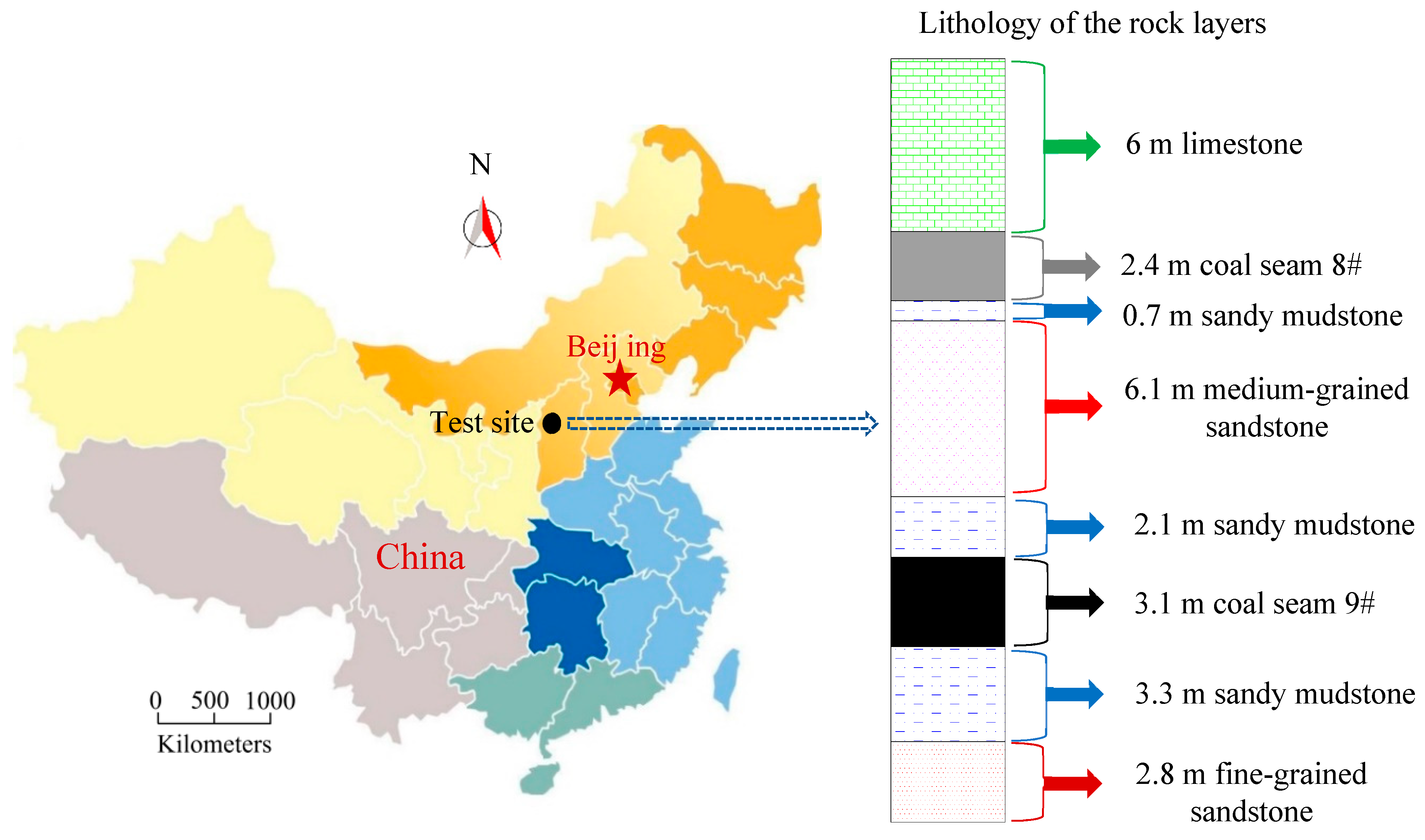
The Dianping coal mine is located in Lvliang City, Shanxi Province, China, and it is the representative mine of the Liuli mining area. At present, coal seam 9# is mainly mined. The mined coal is bituminous and coking coal. The geological condition of the working face is simple, and it is a gas mine. The depth of the 9100 working face is 225–360 m, the length of the open-off cut is 220 m, the length of the entry is 1088 m, and the length of GERRC is 942 m. The coal seam dip angle is 4° and the thickness is 3.1 m with a 293 m overburden. The entry is excavated along the roof and floor of the coal seam, and the entry section is rectangular 3.1 m high and 5.0 m wide. The coal seam roof is a composite rock stratum. The immediate roof is sandy mudstone with an average thickness of 2.1 m, and the main roof is medium-grained sandstone, followed by a 0.7 m thick sandy mudstone, a 2.4 m thick 5# coal and a 6.0 m thick limestone. Below the coal seam, the floor consists of sandy mudstone and fine-grained sandstone, with average thicknesses of 3.3 m and 2.8 m, respectively. The location of the mine and lithology of the rock layers are shown in Figure 10.
4.2. Design of CRLDA Support
To make the CRLDA play a good suspension role in the process of retaining the entry and effectively protect the anchorage end from the blasting damage, the length of the CRLDA is generally designed to be + 2 m, and the anchorage end is located in hard and stable rock. The length of the constant resistance anchorage cable is 13.3 m. In addition, the CRLDA is more favorable for roof support on the mining side. Considering the parameters of roof cutting and the original design support mode of the entry, the CRLDA are arranged perpendicular to the roof direction with two rows. The first row is 500 mm away from the blasthole, the row spacing is 1000 mm, and the adjacent CRLDA is connected by a W-type steel strip. The second row is located in the middle line of the entry, and the distance is 2000 mm. The diameter of the steel strand wire is 21.8 mm, the length and outer diameter of the constant resistance device are 450 mm and 72 mm, the constant resistance value is 33 ± 2 t, and the pretightening force is not less than 28 t. The design and construction of CRLDA supports are shown in Figure 11.
4.3. Design of Directional Presplit Cumulative Blasting
The design parameters of directional presplit cumulative blasting mainly include the angle, depth, spacing of the blastholes and the structure of the charge, and the above parameters are determined by theoretical analysis and field tests.
(1) Blasthole angle
We define the blasthole angle to be the angle between the blasthole and the vertical line. After directional presplit cumulative blasting, a flat fracture surface or weak plane structure is formed between the blastholes. After mining, the roof of the goaf will be completely broken and slipped along the roof fracturing line under its own gravity and overlying strata action force. The construction of blasting is carried out in front of the working face. To prevent the roof from the larger bed separation and subsidence after the blasting, the blasthole needs a certain angle.
The angle should not be too small ( < 10°) to prevent the blasting from disturbing the nearby support. Moreover, when the angle is small, the roof collapse needs to overcome a larger rock shear force, and the vertical supporting force () of the caving gangue to the fracture surface is smaller. The angle should not be too large ( > 25°). The length of the cantilever beam increases after the angle increases. At the same time, the filling effect of the goaf in the area under the large angle is poor, and the entry roof is prone to larger rotating deformation. Field tests prove that the best blasthole angle is 15–20°.
(2) Blasthole depth
The directional presplit cumulative blasting is the core technology to cut off the stress transfer of the roof and realize good filling in the goaf. The height of the roof cutting must be more than the height of the caving zone when the goaf filling is complete, so that the gangue can limit the movement of the main roof rock beam and the overlying rock. Therefore, the depth of the presplit seam drilling is obtained. Therefore, the formulas for depth design are as follows:
where is the working face height; is the initial gangue expansion factor; and .
The mining height of the 9100 working face is 3.1 m, the blasthole angle is 15°, and the gangue expansion factor is 1.4. It is calculated that the blasthole depth design is not less than 8 m.
(3) Blasthole spacing
To achieve good roof cutting, the damage fracture of the two holes should be connected, and the criterion condition is that the damage depth produced by the two blastholes is greater than the hole spacing; the criterion conditions of blasting can be derived as follows [30]:
In the formula, is the center-to-center spacing of the blastholes; is the radius of the blasthole; is the side pressure coefficient, ; is the Poisson’s ratio of the roof rock; is the rock stress; is the peak pressure of the impact wave on the hole wall; is the initial damage parameter of the rock mass; is the rock tensile strength; and is the attenuation coefficient of the explosion stress wave, .
= 24 mm, = 0.3, = 48.3 MPa, = 2200 MPa, = 0.6, and = 3.3 MPa. Substitution Formula (16) is calculated for 524 mm.
In addition, blasthole spacing can be initially designed according to lithology. Under normal conditions, the spacing between hard roof holes is 400–500 mm, and the spacing between composite roof holes is 500–600 mm. The roof of the 9100 working face is a medium strength composite roof. Combined with the calculation results, the spacing between the boreholes is determined to be 500 mm.
4.4. Design of the Surrounding Rock Control in GERRC
In different movement stages of the entry surroundings, targeted measures should be taken to guarantee the stability of the retained entry.
(1) Roof initial movement stage
To ensure the safety and stability of the entry when blasting, the CRLDA is used to strengthen the roof. To control the overall deformation of the entry, advance support is carried out 30 m in front of the working face. The advance support can be used for reference to the original support form of the mine. Generally, hydraulic prop supports are adopted in the roof initial movement stage, but the strength is increased.
(2) Roof severe movement stage
In this stage, the deformation of the surrounding rock is obvious, and the roof subsidence rate is the largest. The entry support strength must ensure the roof subsidence in the controllable range, and the roof of the entry does not break out. The overall subsidence of the roof is mainly derived from two aspects: one is the bed separation and the broken expansion of the roof in the range of the CRLDA support, and the other is the rotational subsidence of the roof caused by the subsidence of the overlying rock beam above the CRLDA support. To increase the support strength of the roof severe movement stage, on the one hand, the bed separation can be controlled, and on the other hand, the impact of the roof collapse and the main roof rock beam fracture can be reduced to realize maximum control of the roof rotation rate to ensure that the roof of the gob is broken down in time and filled well; then, the rotational subsidence of the roof rock beam can be reduced. Generally, a gate-type hydraulic support with high resistance was adopted in the roof severe movement stage.
The ZMX410/220 gate-type hydraulic support with high resistance is used to provide temporary support for the roof of the retaining entry. The support is 3200 mm long and 300 mm wide, and the supporting height range is 2200–4100 mm. The rated working resistance of the gate type hydraulic support is 2040 kN. The support row spacing of 2000 mm is designed. The application of temporary support for the roof in the severe movement stage is shown in Figure 12a.
In addition to strengthening the roof support, the gangue side of the retaining entry also needs support behind the working face. Gangue support plays an important role in guaranteeing the effect of the retaining entry. The prevention gangue structure must have two conditions: one is to ensure that it has scalability when the roof and floor converge closer, and the other is that it has a certain strength and integrity. Because the composite roof caving gangue fragmentation is small, gangue is shown to have a certain fluidity under high stress conditions. The retractable 29# U-shaped steel can is used for preventing gangue behind the working face. The two U-shaped steel beams are 2.0 m and 2.5 m long, respectively. They are connected by two clips. The overlap length is not less than 1 m. The 29# U-shaped steel is buried under the bottom of the floor not less than 300 mm. The application of the gangue prevention design is shown in Figure 12b.
(3) Roof slow movement stage
The deformation rate of the surrounding rock is gradually reduced. When the subsidence rate of the roof is reduced to 1 mm/d, the gate type hydraulic support can be retraced for recycling and gradually retraced by interval.
(4) Roof stable movement stage
Under normal conditions, the entry support retracting is completed, but some of the hydraulic prop supports should be kept in the area of the tunnel chamber intersection, fault zone, roof crusher and big roof subsidence.
5. Research Results
5.1. Mechanical Mechanism of GERRC Technology
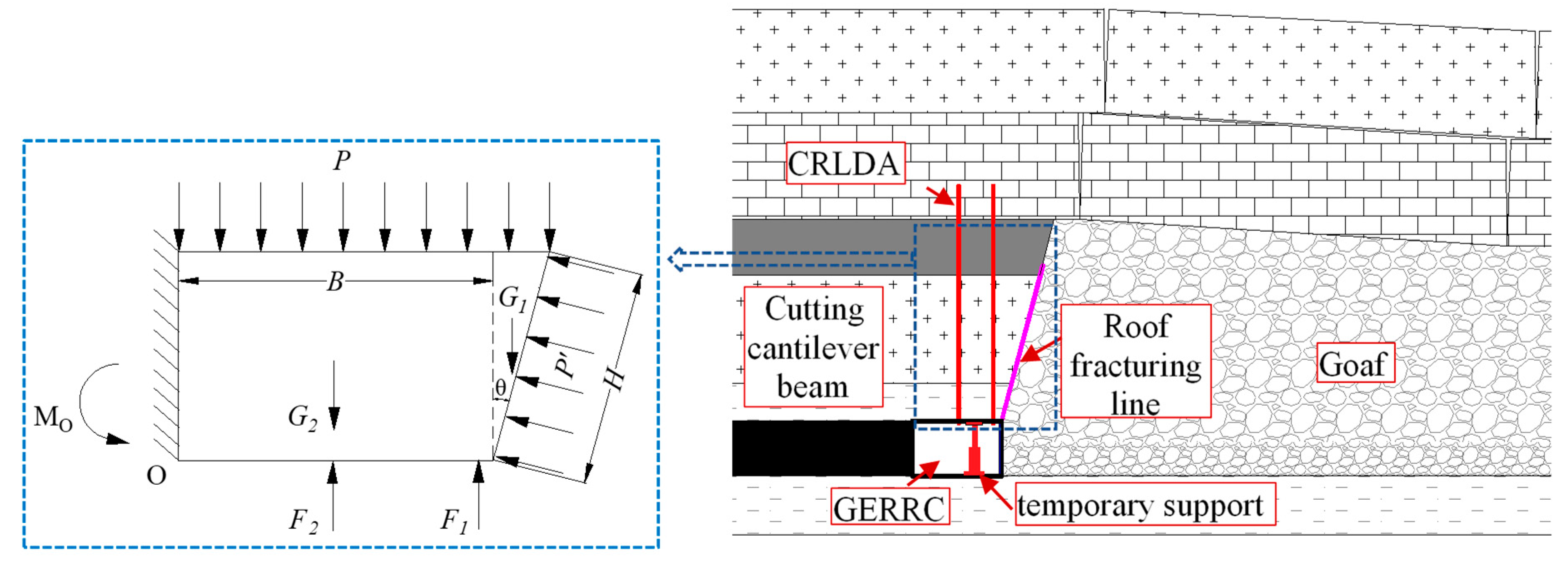
Through the analysis of the principle of GERRC, it can be found that the key to guaranteeing the stability of the retained entry is to ensure the stability of the cutting cantilever beam structure. For this reason, the immediate roof of the entry in the roof cutting area is simplified as a cantilever beam, as shown in Figure 13.
The force in the diagram is acting on the unit width along the strike, where is the pressure of the main roof, is the gangue supporting force, is the force of CRLDA, is the temporary support force, is the roof gravity of the triangle area, is the roof gravity of the rectangular area, is the bending moment in the rock beam, is the width of the retaining entry, and and are the depth and angle of the blasthole, respectively.
Under the condition that the roof does not undergo severe deformation, the stress of the roof meets the principle of moment balance:
Obviously:
In the formula, is the maximum tensile stress of the rock beam, is the dynamic load coefficient of the roof pressure, is the basic top thickness, is the direct top density, is the basic top density, and the is the basic top along the lateral fracture span.
The above analysis shows that the entry roof becomes a cantilever beam with a width of by cutting the roof, and roof cutting is an important factor to guarantee the formation of the retained entry. In addition, from the equations above, we can understand that the force of CRLDA , the temporary support force and the gangue supporting force are the key parameters to ensure that the mechanical balance of the cutting cantilever beam. Therefore, in-depth study of the key technologies of GERRC is of great significance.
5.2. Mechanical Properties and Application Effects of CRLDA
5.2.1. Mechanical Properties of CRLDA
The tensile results obtained by the LEW-500 anchor cable tensile test system are shown in Figure 14a. The maximum tensile slip deformation is between 386.38 mm and 405.38 mm, and the tensile force is maintained at approximately 320 kN, indicating that the constant resistance performance is good. In addition, after several drop impact tests, the force and slip tensile deformation of CRLDA under different impact energy are obtained, as shown in Figure 14b. The experimental results show that CRLDA does not break under repeated impact, showing the characteristics of high constant resistance and large deformation.
It can be seen from above that the constant resistance device has three properties: high pretightening force, large deformation, and good impact resistance. The pretightening force of the traditional anchor cable is generally 150 kN. Because of the low pretightening force, control of the initial deformation of the entry surrounding rock is unfavorable. The CRLDA can achieve approximately 280 kN of pretightening force, which is two times the pretightening force of traditional anchor cable. The application of CRLDA to medium thick coal seams with compound roofs is favorable for surrounding rock control before the retaining entry. The constant resistance is beneficial to the full use of the surrounding rock bearing characteristics, and the impact resistance provides a safety guarantee for the directional presplit blasting and roof fracture impact. These three excellent characteristics ensure that CRLDA can be well applied to support the surrounding rock of GERRC under medium-thick seam and compound roof conditions.
5.2.2. Support Effects of CRLDA in the Field Experiment
By monitoring the force of the CRLDA and the shrinkage of the lock, the curves of the force and shrinkage of the CRLDA with the advancing working face are obtained, as shown in Figure 15.
From the above charts, it can be found that the roof initial movement stage begins at 33 m in front of the working face, and the stress of the roof increases gradually. The roof severe movement stage is accompanied by the periodic impact of the roof, and the force of the CRLDA fluctuates. At the roof severe movement stage, the strength of roof movement decreases, and the force and shrinkage of CRLDA increase with the increase of roof surrounding rock deformation. When the distance behind the working faces is greater than 160 m, the roof movement reaches a stable stage, and the force and shrinkage of CRLDA are basically stable. At the same time of the periodic fracture and impact of the roof, the CRLDA shrinkage increases, indicating that the impact resistance of the CRLDA is superior and can absorb the impact potential energy of the roof.
5.3. Effects of Directional Presplit Cumulative Blasting Technology
5.3.1. Analysis of Numerical Simulation Results
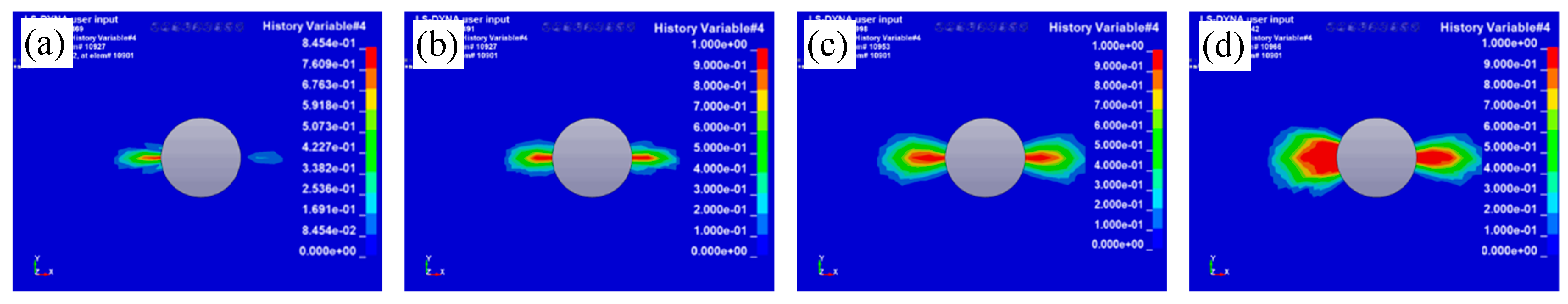
As shown in Figure 16 and Figure 17, the stress field and rock damage distribution are obtained under the cumulative blasting condition using a numerical simulation method.
Under cumulative blasting, the stress wave produced by the explosion directly affects the hole wall through the energy cumulative hole at t = 3.922 μs, and the “pen tip type” stress field is formed in the energy cumulative direction. The initial damage is formed at 6 mm from the wall of the hole. At time t = 9.4889 μs, the explosion stress wave transmission tube is applied to the hole wall in the nonenergy cumulative direction and the stress field is expanded outward to form a double “tie type” stress field. The stress of the inner layer is approximately 10–50 times the outer layer, and tensile stress is produced in the energy cumulative direction. The damage length is continuously extended, and the damage is linearly distributed along the radial energy cumulative direction. The tension stress field extends to the nonenergy cumulative direction. At t = 33.998 μs, the front end of the tensile stress field is closed around the blast hole and forms an elliptical compressive stress field. The total damage length of the hole wall is 50 mm, and the damage area extends along the radial direction. Finally, the simulation results show that the damage propagates along the energy cumulative direction and there is no obvious damage in the nonenergy cumulative direction after directional presplit cumulative blasting.
It is obvious that, when the blasting is controlled, the damage only propagates in the desired direction. After the cracks between the blastholes are connected, a fracturing line can be formed along the mining direction and the entry roof becomes a cantilever beam, as illustrated in the theoretical analysis section (Figure 13). Therefore, the roof cutting effects can directionally determine the formation of the roof cantilever beam and then affects the stability of the retained entry.
5.3.2. Application Effects in the Field Experiment
Directional presplit cumulative blasting can directly affect the application effects of GERRC. The blasting test must be carried out in advance to determine the final charge structure. First, a single hole blasting test is carried out according to the above design parameters to determine the initial charge structure, and then continuous blasting is carried out, and the charge structure is adjusted in time by observing the crack in the hole after blasting. The higher the crack rate in the hole is, the better the effect of presplitting, and a reasonable charge structure occurs when the crack rate is more than 70% in the hole.
In the field test, the size of the emulsion explosive is φ27 × 300 mm, and each weight is 200 g. Each hole has four 1.5 m long energy cumulative tubes and one 0.75 m long energy cumulative tube, and the sealing length is 2.25 m. The results show that the optimum charge structure is “4 explosives + 3 explosives + 4 explosives + 3 explosives + 2 explosives”, the average crack rate of the hole after blasting is up to 81%, and the roof of the goaf after mining is broken down in time along the roof fracturing line, indicating that the effect of presplitting blasting is better. The structure of charge and the effect of directional presplit cumulative blasting are shown in Figure 18.
5.4. Effects of the Surrounding Rock Control in the Field Experiment
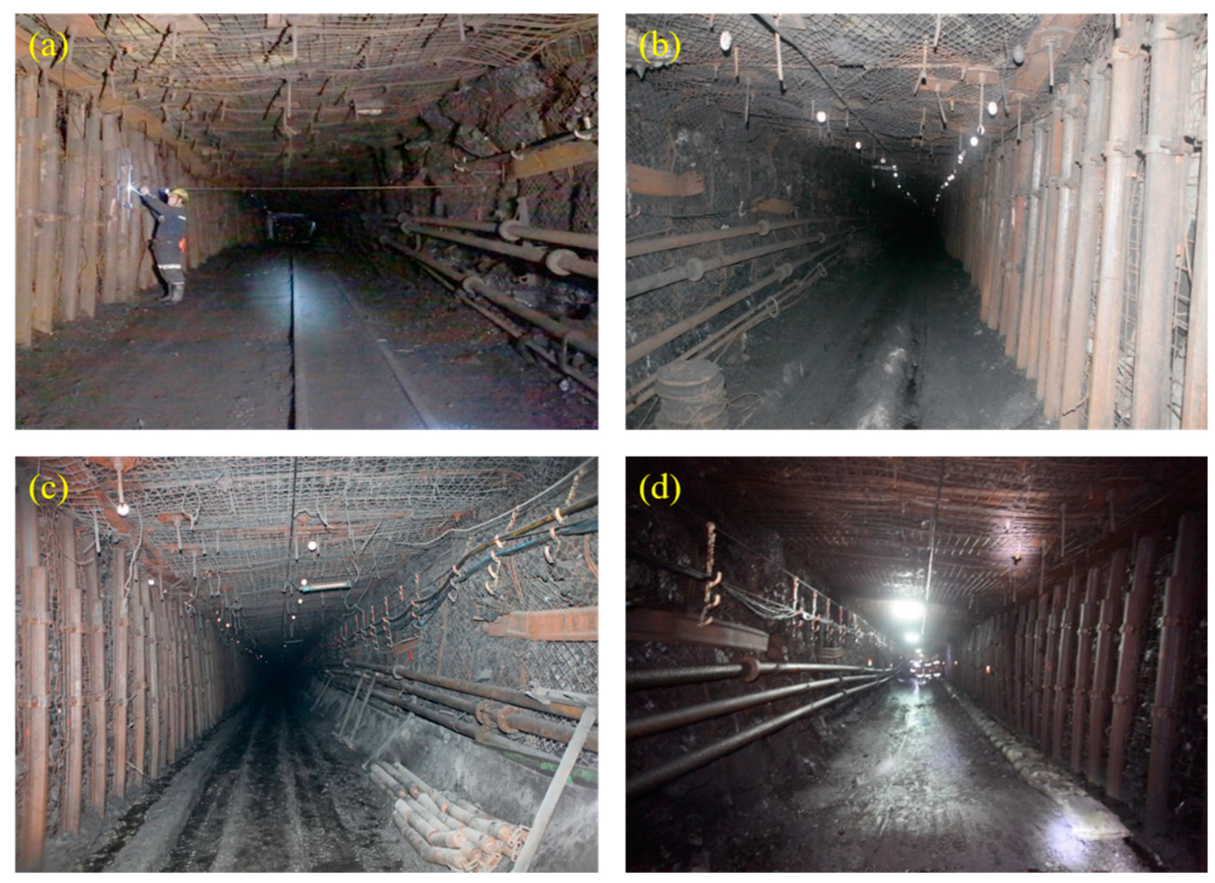
Under medium-thick coal seam and compound roof conditions, the proposed noncoal pillar mining approach and key technologies were tested in the Dianping coal mine. After application of the new approach, the recovery of coal pillar resources reaches 82 thousand tons, creating direct economic benefits of nearly 100 million yuan. The normal advancing speed of the working face is 7 m per day, and the roof temporary support is removed in the section approximately 160 m behind the working face. The application effects of GERRC are shown in Figure 19. The final section of GERRC met the safety production requirements, verifying that the proposed technology for nonpillar mining in medium-thick coal seam and compound roof conditions is feasible.
6. Discussion
In this study, three key technologies for GERRC were proposed and comprehensively studied using various methods. It was suggested that the proposed key technologies for GERRC were effective and the application of GERRC in medium-thick coal seam and compound roof conditions was feasible. For GERRC, the deformation and pressure of the entry surroundings are import factors reflecting the stability of the retained entry. Based on the field monitoring results, the deformation of the entry surroundings and pressure of the temporary support in the retained entry are discussed.
(1) Deformation of the entry surroundings
Through the deformation monitoring of surrounding entry rock, the roof and floor displacement curves, two sides and roof bed-separation and the rate of roof subsidence are obtained as shown in Figure 20. From the above monitored results, we can see that:
(1) When the distance behind the working faces is greater than 160 m, the surrounding entry rock is basically stable. The final roof-to-floor convergence is 439 mm, the roof subsidence is 186 mm, the floor heave is 253 mm, the two sides of entry convergence are 330 mm, the gangue side moves near 201 mm, and the coal side displacement is 129 mm.
(2) The determination of the roof subsidence rate as the roof movement degree: the roof subsidence rate is greater than 5 mm/d for the roof severe movement stage, 1–5 mm/d in the roof slow movement stage, and less than 1 mm/d in the roof stable movement stage. The subsidence rate is 5–18 mm/d 0~60 m behind the working face, which is the roof severe movement stage, and 1–10 mm/d 60–160 m behind the working face, which is the roof slow movement stage. The roof is in the stable stage when the distance behind the working face is greater than 160 m.
(3) The roof bed-separation value increases rapidly during the roof severe movement stage within the 60 m range behind the working face. The degree of roof movement weakened, and the bed-separation showed a slow increasing trend in the roof slow movement. When the distance behind the working face is greater than 160 m, the movement of the roof reaches a stable stage, the bed-separation is basically stable, and the final separation value is 54 mm, which is similar to the shrinkage deformation of the CRLDA.
(2) Pressure of the temporary support in the retained entry
The pressures of the gate-type hydraulic supports in the retained entry were monitored, as shown in Figure 21. In the roof severe movement stage, the working resistance rises rapidly. With the periodic fracture impact of the roof, the working resistance of the gate-type hydraulic support appears to fluctuate greatly. The resistance of portal supports fluctuates slightly in the roof slow movement. In the roof stable movement stage, the working resistance is basically stable, and gate-type hydraulic support can be removed for recycling. Overall, the working resistance of the gangue side column is obviously larger than the coal side column indicating that the supporting strength and the monitoring of the mine pressure on the gangue side should be strengthened. It also indicates that the arrangement of CRLDA near the gangue side is reasonable.
7. Conclusions
In China, coal provides most of the energy for economic and industrial development. For sustainable utilization of limited coal resources, it is important to increase the coal recovery rate and improve entry stabilities. In the present study, an innovative noncoal pillar mining approach for medium-thick coal seam and compound roof conditions has been proposed. Three key technologies (i.e., CRLDA support technology, directional presplit cumulative blasting technology and surrounding rock control technology) for the innovative approach were further introduced and systematically studied by theoretical analysis, numerical simulation, laboratory and field experiments.
By establishing structural and mechanical models, the mechanism of GERRC was analyzed theoretically. In addition, the working mechanism and mechanical properties of CRLDA were experimentally studied. Furthermore, the principle of directional presplit cumulative blasting technology and the energy cumulative effect of the energy cumulative tube were analyzed by numerical modeling. The feasibility of GERRC applied in medium-thick coal seam and compound roof conditions was verified by a field experiment. The results show that the roof movement of GERRC can be divided into four stages, i.e., the initial movement stage, the severe movement stage, the slow movement stage and the stable movement stage. A gate-type hydraulic support can be used to support the roof temporarily, and the retractable U-shaped steel can well prevent the gangue from rolling into the entry. When the distance behind the working faces is greater than 160 m, the surrounding entry rock is basically stable. In the roof severe movement stage, the working resistance rises rapidly. With the periodic fracture impact of the roof, the working resistance of the temporary support appears to fluctuate greatly. In the roof stable movement stage, the working resistance is basically stable. The final section of GERRC meets the safety production requirements, verifying that the proposed technology for nonpillar mining in medium-thick coal seam and compound roof conditions is feasible. The key technologies and design methods obtained in this study can provide a good reference for effective mining of bituminous and coking coals under similar conditions.
Author Contributions
M.H. and Y.G. conceived and designed the research. J.W. and J.H. performed the numerical simulation and field tests; Q.W. provided theoretical guidance in the research process; Z.M. and Y.G. analyzed the data and wrote the paper.
Funding
This research was funded by the National Natural Science Foundation of China grant number No. 51574248, No. 51674265, and the State Key Research Development Program of China grant number No. 2016YFC0600900.
Conflicts of Interest
The authors declare no conflict of interest.
References
- Qian, M.; Miao, X.; He, F. Analysis of key block in the structure of voussoir beam in longwall mining. J. China Coal Soc. 1994, 31, 191A. [Google Scholar]
- Zheng, X.; Yao, Z.; Zhang, N. Stress distribution of coal pillar with gob-side entry driving in the process of excavation & mining. J. Min. Saf. Eng. 2012, 29, 459–465. [Google Scholar]
- Zhang, Z.; Bai, J.; Chen, Y.; Yan, S. An innovative approach for gob-side entry retaining in highly gassy fully-mechanized longwall top-coal caving. Int. J. Rock Mech. Min. Sci. 2015, 80, 1–11. [Google Scholar] [CrossRef]
- Basarir, H.; Oge, I.; Aydin, O. Prediction of the stresses around main and tail gates during top coal caving by 3D numerical analysis. Int. J. Rock Mech. Min. Sci. 2015, 76, 88–97. [Google Scholar] [CrossRef]
- Yang, H.; Cao, S.; Wang, S.; Fan, Y.; Wang, S.; Chen, X. Adaptation assessment of gob-side entry retaining based on geological factors. Eng. Geol. 2016, 209, 143–151. [Google Scholar] [CrossRef]
- Guy, R.; Kent, M.; Russell, F. An assessment of coal pillar system stability criteria based on a mechanistic evaluation of the interaction between coal pillars and the overburden. Int. J. Min. Sci. Technol. 2017, 27, 9–15. [Google Scholar]
- Tesarik, D.R.; Seymour, J.B.; Yanske, T.R. Long-term stability of a backfilled room-and-pillar test section at the Buick Mine, Missouri, USA. Int. J. Rock Mech. Min. Sci. 2009, 46, 1182–1196. [Google Scholar] [CrossRef]
- He, M.; Zhu, G.; Guo, Z. Longwall mining “cutting cantilever beam theory” and 110 mining method in China—The third mining science innovation. J. Rock Mech. Geot. Eng. 2015, 7, 483–492. [Google Scholar] [CrossRef]
- Zhang, G.; He, M.; Yu, X.; Huang, Z. Research on the technique of no-pillar mining with gob-side entry formed by advanced roof caving in the protective seam in Baijiao coal mine. J. Min. Saf. Eng. 2011, 28, 511–516. [Google Scholar]
- Zhang, G.; Xu, Y.; Ge, P. Research on cut gob-side entry retaining in thin coal seam of Tangshan ditch. Chin. J. Rock Mech. Eng. 2016, 35, 1397–1406. [Google Scholar]
- Sun, X.; Xin, L.; Liang, G.; Dong, W.; Jiang, Y. Key parameters of gob-side entry retaining formed by roof cut and pressure releasing in thin coal seams. Chin. J. Rock Mech. Eng. 2014, 33, 1449–1456. [Google Scholar]
- He, M.; Gao, Y.; Yang, J.; Gong, W. An Innovative approach for gob-side entry retaining in thick coal seam longwall mining. Energies 2017, 10, 1785. [Google Scholar] [CrossRef]
- Gao, Y.; Liu, D.; Zhang, X.; He, M. Analysis and optimization of entry stability in underground longwall mining. Sustainability 2017, 9, 2079. [Google Scholar] [CrossRef]
- Wang, Y.; Gao, Y.; Wang, E.; He, M.; Yang, J. Roof deformation characteristics and preventive techniques using a novel non-pillar mining method of gob-side entry retaining by roof cutting. Energies 2018, 11, 627. [Google Scholar] [CrossRef]
- He, M.; Wang, J.; Sun, X.; Yang, X. Mechanics characteristics and applications of prevention and control rock bursts of the negative poisson’s ratio effect anchor. J. China Coal Soc. 2014, 39, 214–221. [Google Scholar]
- He, M.; Gong, W.; Wang, J.; Qi, P.; Tao, Z.; Du, S.; Peng, Y. Development of a novel energy-absorbing bolt with extraordinarily large elongation and constant resistance. Int. J. Rock Mech. Min. Sci. 2014, 67, 29–42. [Google Scholar] [CrossRef]
- He, M.; Li, C.; Gong, W.; Sousa, L.R.; Li, S. Dynamic tests for a constant-resistance-large-deformation bolt using a modified SHTB system. Tunn. Undergr. Space Tech. 2017, 64, 103–116. [Google Scholar] [CrossRef]
- Zhang, G.; Wang, E.; Xu, L. Mechanical characteristics of high constant resistance and large deformation anchor rope in coal mines. Chin. J. Rock Mech. Eng. 2016, 35, 2033–2043. [Google Scholar]
- Chen, J.; Zhang, J.; Li, X. Study of presplitting blasting parameters and its application based on rock blasting-induced damage theory. Rock Soil Mech. 2016, 37, 1441–1450. [Google Scholar]
- Gao, Y.; He, M.; Yang, J.; Ma, X. Experimental study of caving and distribution of gangues influenced by roof fracturing in pillarless mining with gob-side entry retaining. J. China Univ. Min. Technol. 2018, 47, 21–31. [Google Scholar]
- Konicek, P.; Soucek, K.; Stas, L.; Singh, R. Long-hole destress blasting for rockburst control during deep underground coal mining. Int. J. Rock Mech. Min. Sci. 2013, 61, 141–153. [Google Scholar] [CrossRef]
- Yilmaz, O.; Unlu, T. Three dimensional numerical rock damage analysis under blasting load. Tunn. Undergr. Space Tech. 2013, 38, 266–278. [Google Scholar] [CrossRef]
- Yang, G.; Yang, R.; Tong, J. Research and application of cut blasting with slotted charge. J. China Coal Soc. 2012, 37, 385–388. [Google Scholar]
- He, M.; Cao, W.; Shan, R.; Wang, S. New blasting technology-bilateral cumulative tensile explosion. Chin. J. Rock Mech. Eng. 2003, 22, 2047–2051. [Google Scholar]
- Xie, L.; Lu, W.; Zhang, Q.; Jiang, Q.; Wang, G.; Zhao, J. Damage evolution mechanisms of rock in deep tunnels induced by cut blasting. Tunn. Undergr. Space Tech. 2016, 58, 257–270. [Google Scholar] [CrossRef]
- Zhu, Z.; Mohanty, B.; Xie, H. Numerical investigation of blasting-induced crack initiation and propagation in rocks. Int. J. Rock Mech. Min. Sci. 2007, 44, 412–424. [Google Scholar] [CrossRef]
- Bendezu, M.; Romanel, C.; Roehl, D. Finite element analysis of blast-induced fracture propagation in hard rocks. Comput. Struct. 2017, 182, 1–13. [Google Scholar] [CrossRef]
- Xie, L.; Lu, W.; Zhang, Q.; Jiang, Q.; Chen, M.; Zhao, J. Analysis of damage mechanisms and optimization of cut blasting design under high in-situ stresses. Tunn. Undergr. Space Tech. 2017, 66, 19–33. [Google Scholar] [CrossRef]
- Li, X.; Huang, J.; Luo, Y.; Chen, P. A study of smooth wall blasting fracture mechanisms using the timing sequence control method. Int. J. Rock Mech. Min. Sci. 2017, 92, 1–8. [Google Scholar] [CrossRef]
- He, M.; Gao, Y.; Yang, J.; Guo, Z.; Wang, E.; Wang, Y. An energy-gathered roof cutting technique in no-pillar mining and its impact on stress variation in surrounding rocks. Chin. J. Rock Mech. Eng. 2017, 36, 1314–1325. [Google Scholar]
Figure 1.
Three typical coal mining modes. (a) mining with a wide coal pillar; (b) mining with a narrow coal pillar; (c) traditional Gob-side Entry Retaining by filling artificial materials.
Figure 1.
Three typical coal mining modes. (a) mining with a wide coal pillar; (b) mining with a narrow coal pillar; (c) traditional Gob-side Entry Retaining by filling artificial materials.

Figure 2.
Schematic diagram of nonpillar mining with Gob-Side Entry Retaining by Roof Cutting.

Figure 3.
Technological process of GERRC.
Figure 4.
Schematic diagrams of constant resistance and large deformation anchor cable. (a) overall structure; (b) section structure.
Figure 4.
Schematic diagrams of constant resistance and large deformation anchor cable. (a) overall structure; (b) section structure.

Figure 5.
Working principle of the CRLDA cable.
Figure 6.
Polyvinyl chloride energy cumulative tube and radial charge structure.
Figure 7.
Stress model of directional presplit cumulative blasting.
Figure 8.
Laboratory test systems for CRLDA. (a) LEW-500 anchor cable tensile test system; (b) dynamic impact test system.
Figure 8.
Laboratory test systems for CRLDA. (a) LEW-500 anchor cable tensile test system; (b) dynamic impact test system.

Figure 9.
Schematic diagrams of numerical model. (a) energy cumulative tube; (b) cumulative blasting.
Figure 9.
Schematic diagrams of numerical model. (a) energy cumulative tube; (b) cumulative blasting.

Figure 10.
Location of the mine and lithology of the rock layers.

Figure 11.
Design of CRLDA support in the Dianping coal mine.

Figure 12.
Design of the surrounding rock control in GERRC. (a) roof temporary support; (b) gangue prevention support.
Figure 12.
Design of the surrounding rock control in GERRC. (a) roof temporary support; (b) gangue prevention support.

Figure 13.
Mechanical model of the GERRC.

Figure 14.
Properties of CRLDA. (a) tensile characteristic curve; (b) impact force-deformation relation curve.
Figure 14.
Properties of CRLDA. (a) tensile characteristic curve; (b) impact force-deformation relation curve.

Figure 15.
Force and shrinkage monitoring curves of CRLDA. (a) force monitoring and curve of CRLDA; (b) shrinkage monitoring and curve of CRLDA.
Figure 15.
Force and shrinkage monitoring curves of CRLDA. (a) force monitoring and curve of CRLDA; (b) shrinkage monitoring and curve of CRLDA.
Figure 16.
Stress cloud map of cumulative blasting. (a) t = 3.922 μs; (b) t = 9.4889 μs; (c) t = 33.998 μs; (d) t = 122.36 μs.
Figure 16.
Stress cloud map of cumulative blasting. (a) t = 3.922 μs; (b) t = 9.4889 μs; (c) t = 33.998 μs; (d) t = 122.36 μs.

Figure 17.
Damage variation of cumulative blasting. (a) t = 18.469 μs; (b) t = 22.491 μs; (c) t = 33.998 μs; (d) t = 108.42 μs.
Figure 17.
Damage variation of cumulative blasting. (a) t = 18.469 μs; (b) t = 22.491 μs; (c) t = 33.998 μs; (d) t = 108.42 μs.

Figure 18.
Charge structure and blasting effects in the field experiment.
Figure 19.
Effects of the surrounding rock control in the Dianping coal mine. (a) 100 m from open-off cut; (b) 200 m from open-off cut; (c) 300 m from open-off cut; (d) 400 m from open-off cut.
Figure 19.
Effects of the surrounding rock control in the Dianping coal mine. (a) 100 m from open-off cut; (b) 200 m from open-off cut; (c) 300 m from open-off cut; (d) 400 m from open-off cut.

Figure 20.
Deformation of entry surrounding rock using GERRC. (a) displacement of the entry roof and floor behind the working face; (b) displacement of two sides of the entry behind the working face; (c) roof subsidence rate; (d) roof bed-separation.
Figure 20.
Deformation of entry surrounding rock using GERRC. (a) displacement of the entry roof and floor behind the working face; (b) displacement of two sides of the entry behind the working face; (c) roof subsidence rate; (d) roof bed-separation.

Figure 21.
Monitored pressure of the gate type hydraulic support in the retained entry.

© 2018 by the authors. Licensee MDPI, Basel, Switzerland. This article is an open access article distributed under the terms and conditions of the Creative Commons Attribution (CC BY) license (http://creativecommons.org/licenses/by/4.0/).
Share and Cite
MDPI and ACS Style
Ma, Z.; Wang, J.; He, M.; Gao, Y.; Hu, J.; Wang, Q. Key Technologies and Application Test of an Innovative Noncoal Pillar Mining Approach: A Case Study. Energies 2018, 11, 2853. https://doi.org/10.3390/en11102853
AMA Style
Ma Z, Wang J, He M, Gao Y, Hu J, Wang Q. Key Technologies and Application Test of an Innovative Noncoal Pillar Mining Approach: A Case Study. Energies. 2018; 11(10):2853. https://doi.org/10.3390/en11102853
Chicago/Turabian StyleMa, Zimin, Jiong Wang, Manchao He, Yubing Gao, Jinzhu Hu, and Qiong Wang. 2018. "Key Technologies and Application Test of an Innovative Noncoal Pillar Mining Approach: A Case Study" Energies 11, no. 10: 2853. https://doi.org/10.3390/en11102853
Note that from the first issue of 2016, this journal uses article numbers instead of page numbers. See further details here.