Wind Micro-Turbine Networks for Urban Areas: Optimal Design and Power Scalability of Permanent Magnet Generators

 , ,
, ,  and
and
Abstract
:1. Introduction
2. Main Components of the Proposed Electromechanical Energy Conversion System
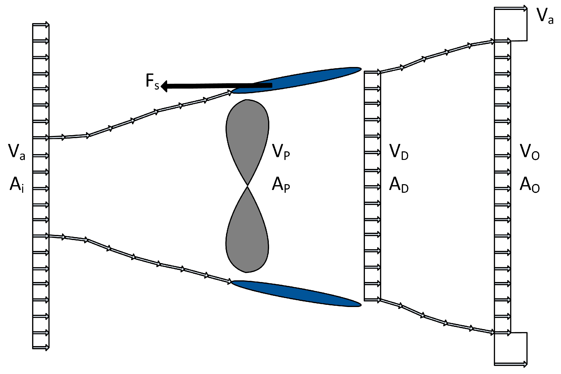
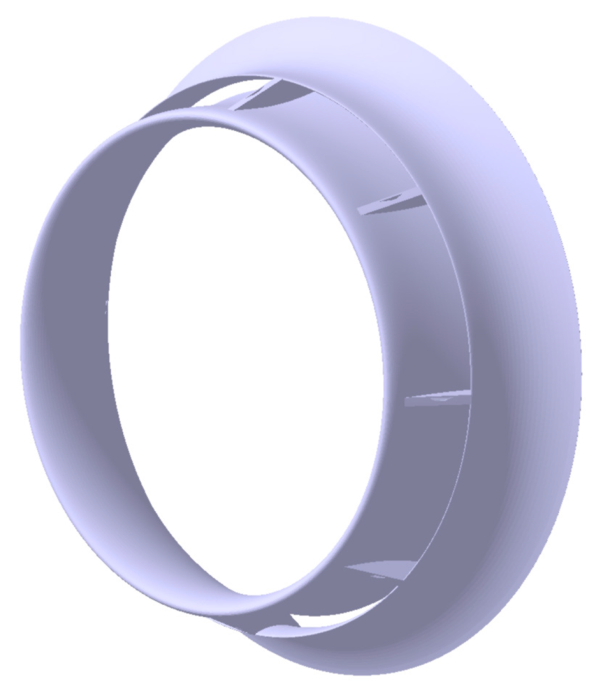
2.1. Ducted Wind Turbine
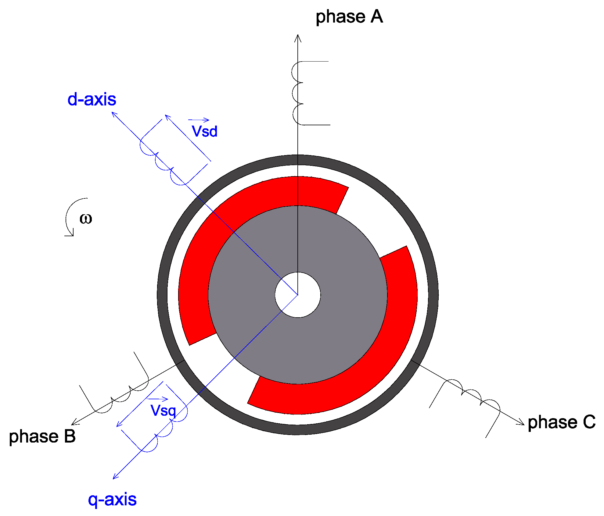
2.2. Permanent Magnet Generator
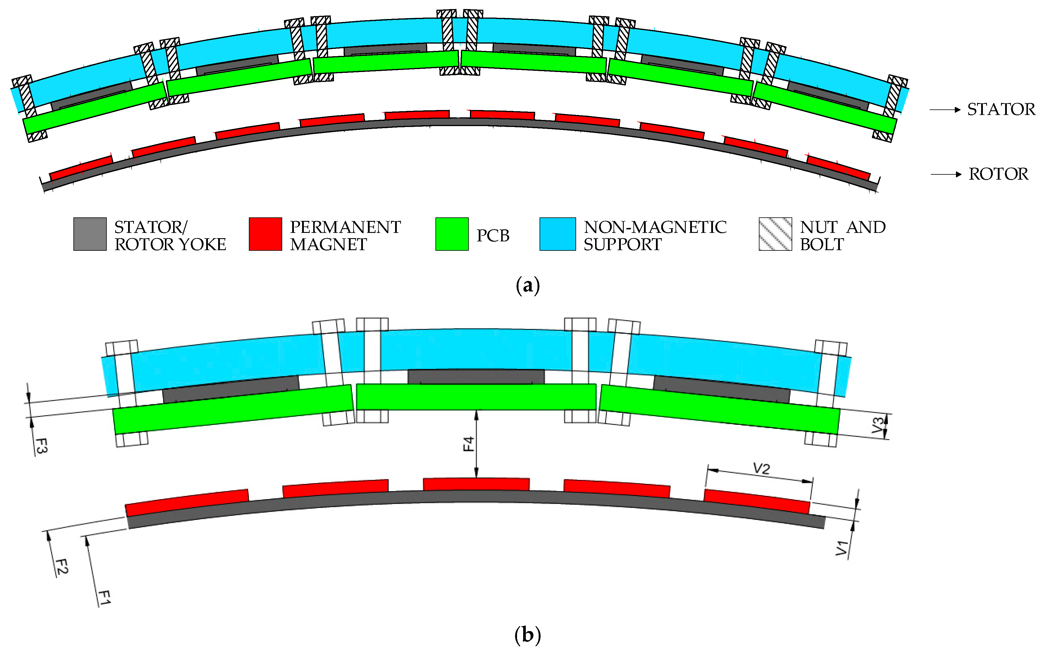
- a segmented back iron, composed by one U-shaped core for each phase coil, can be used for the stator (as shown in Figure 5a); this solution allows to reduce the weight of the stator yoke and makes easier the manufacturing and assembly process, especially for machines with large diameters; and,
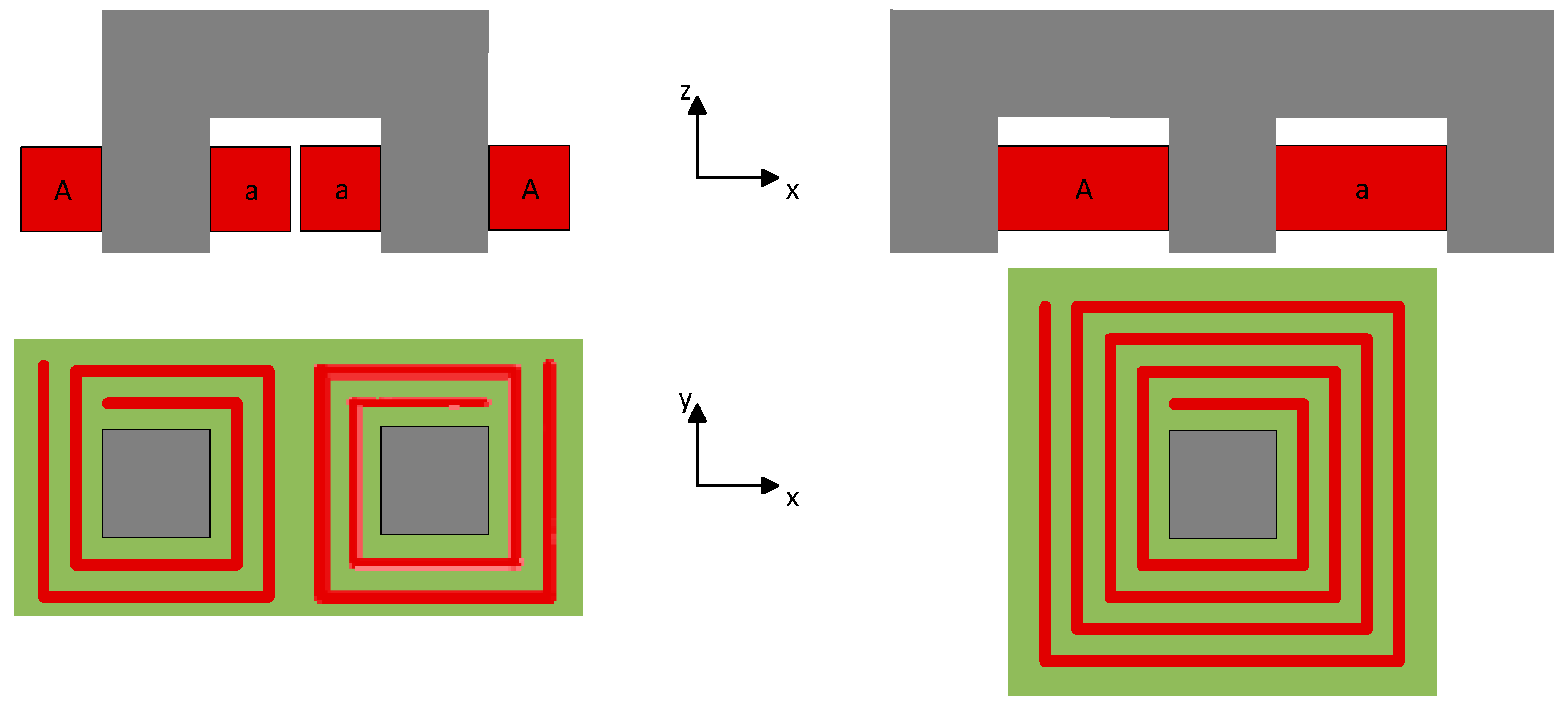
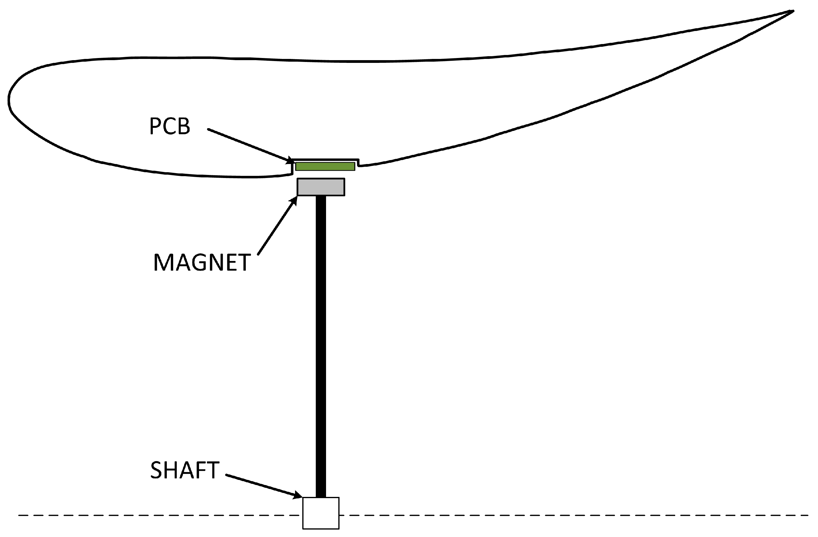
- for a given number of turns and thickness of the copper traces, the dimensions of the PCB in the axial direction can be shortened (as schematically shown in Figure 6); this is due to the reduction of the non-active parts of each phase coil.
3. Scalability Rules
4. Automated Design Tool
4.1. Multi-Objective Optimization
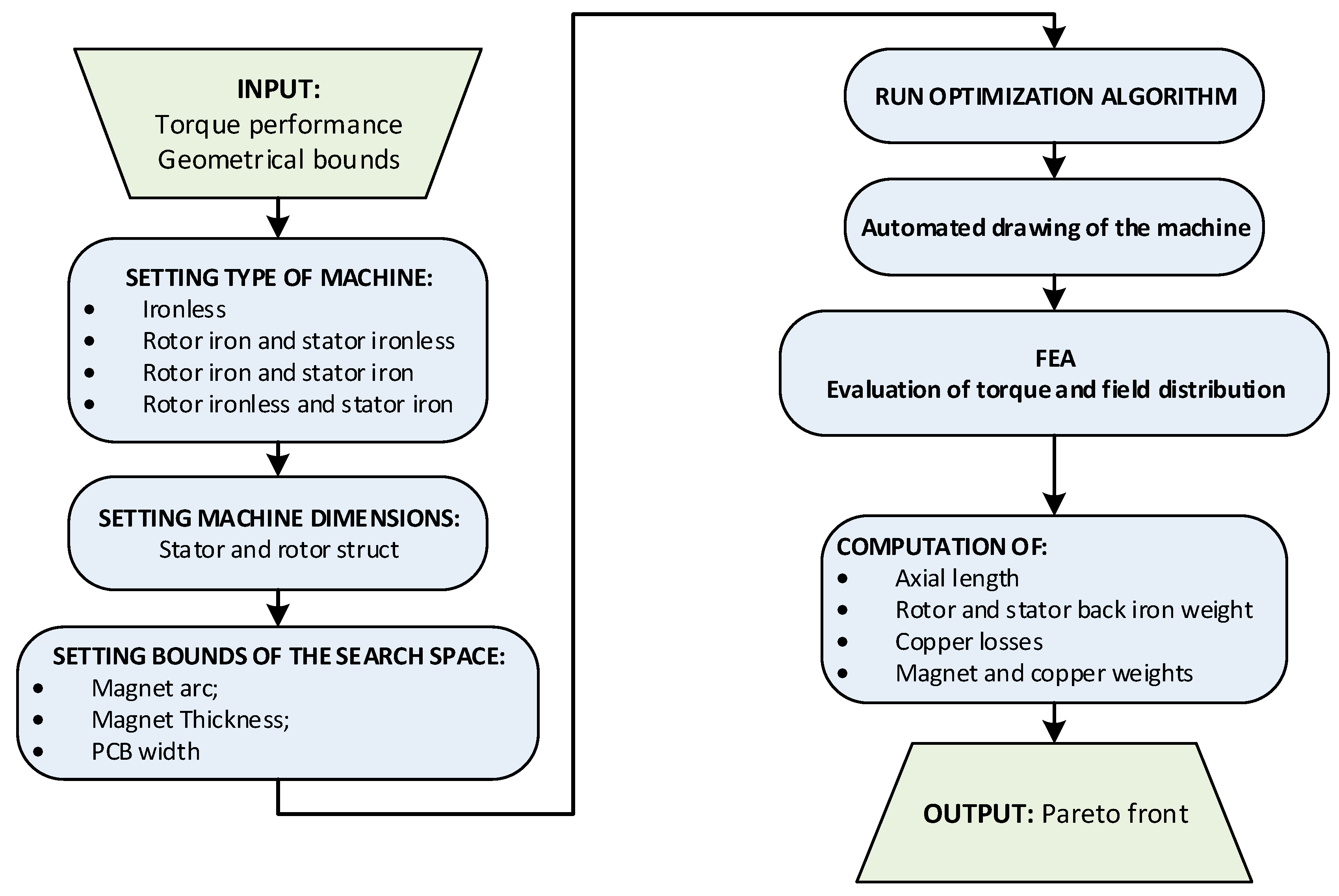
- two-dimensional (2D) magneto-static simulations are performed, considering few equally spaced rotor positions along one pole pitch;
- the electrical machine geometry is described by a limited number of parameters;
- a reduced portion of the entire geometry is analyzed, taking advantage of the machine symmetries; and,
- the computation is parallelized among all the cores of a workstation through the parallel toolbox provided by Matlab.
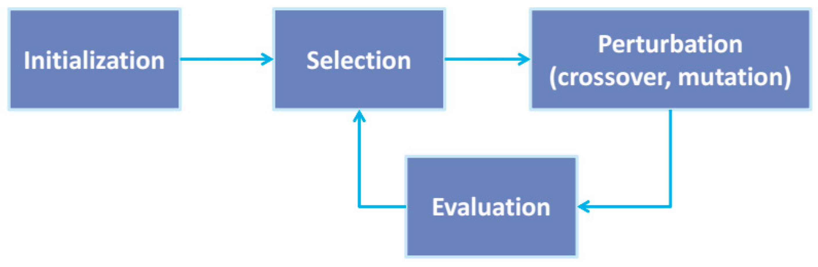
Meta-Heuristic Algorithm
- a combined population CP(i) is formed considering a set P(i) of Npop solutions originated from the (i − 1)-th iteration and a second set Q(i) of Npop solutions obtained from P(i), through crossover and mutation;
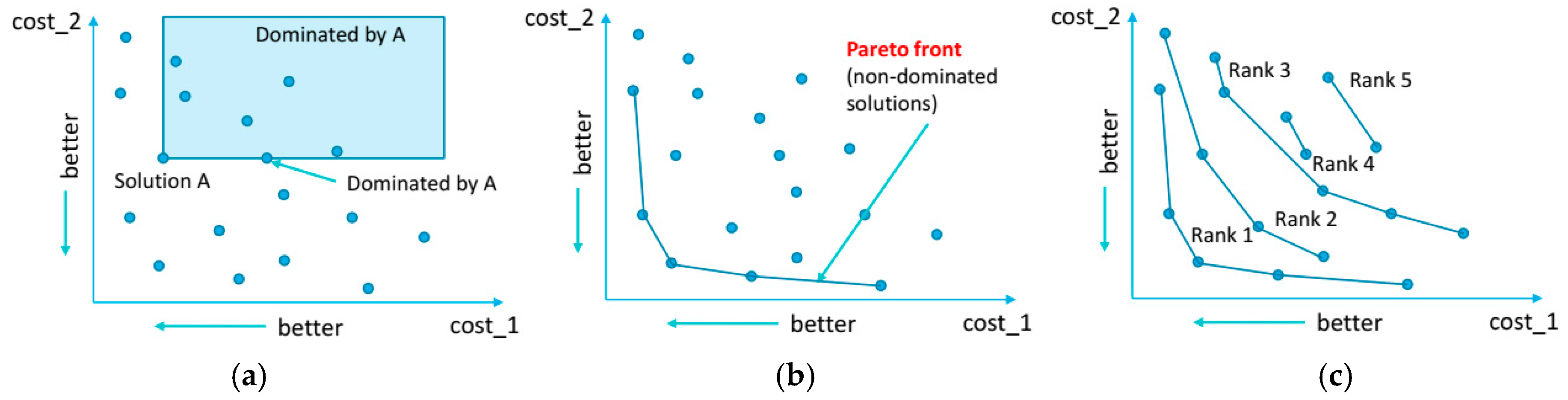
- the population CP(i), whose size is 2Npop, is sorted according to the non-domination criterion; therefore, a rank is assigned to each solution based on its non-domination level;
- Npop solutions are collected, starting from the 1st rank, in order to form the set P(i + 1); if the number of solutions belonging to the 1st rank is less than Npop, the remaining candidates are collected from the subsequent non-dominated set (i.e., the 2nd rank) and so on until the size Npop is reached; and,
- the combined population CP(i + 1) for the (i + 1)-th iteration is finally obtained considering the combination between the population P(i + 1) and the population Q(i + 1) originated from P(I + 1) through crossover and mutation.
4.2. Machine Parameterization
4.3. Cost Functions
- the material cost, which is proportional to the weight for both the PMs and the copper, is indirectly considered; and,
- the impact of the mechanical issues related to the rotor integrity, which are proportional to the rotor mass, can be estimated.
5. Case of Study
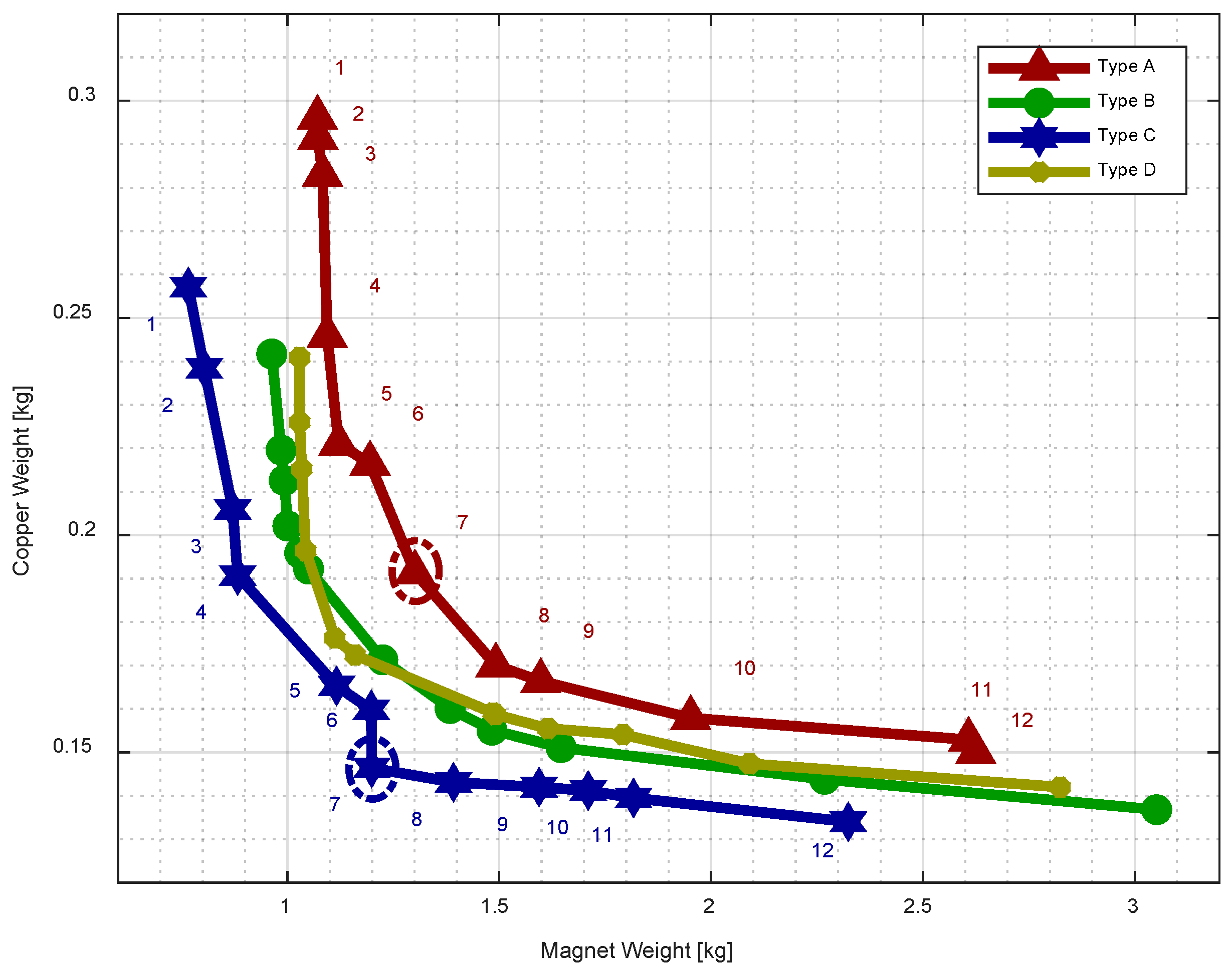
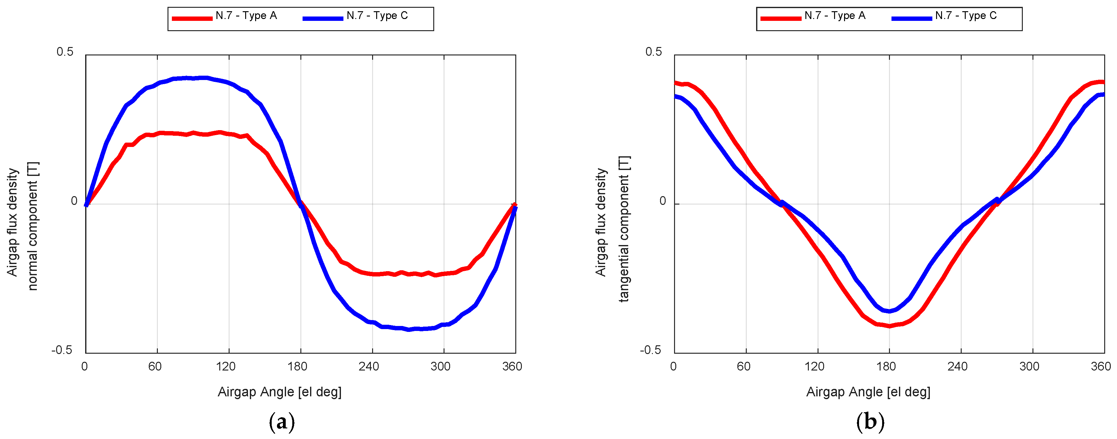
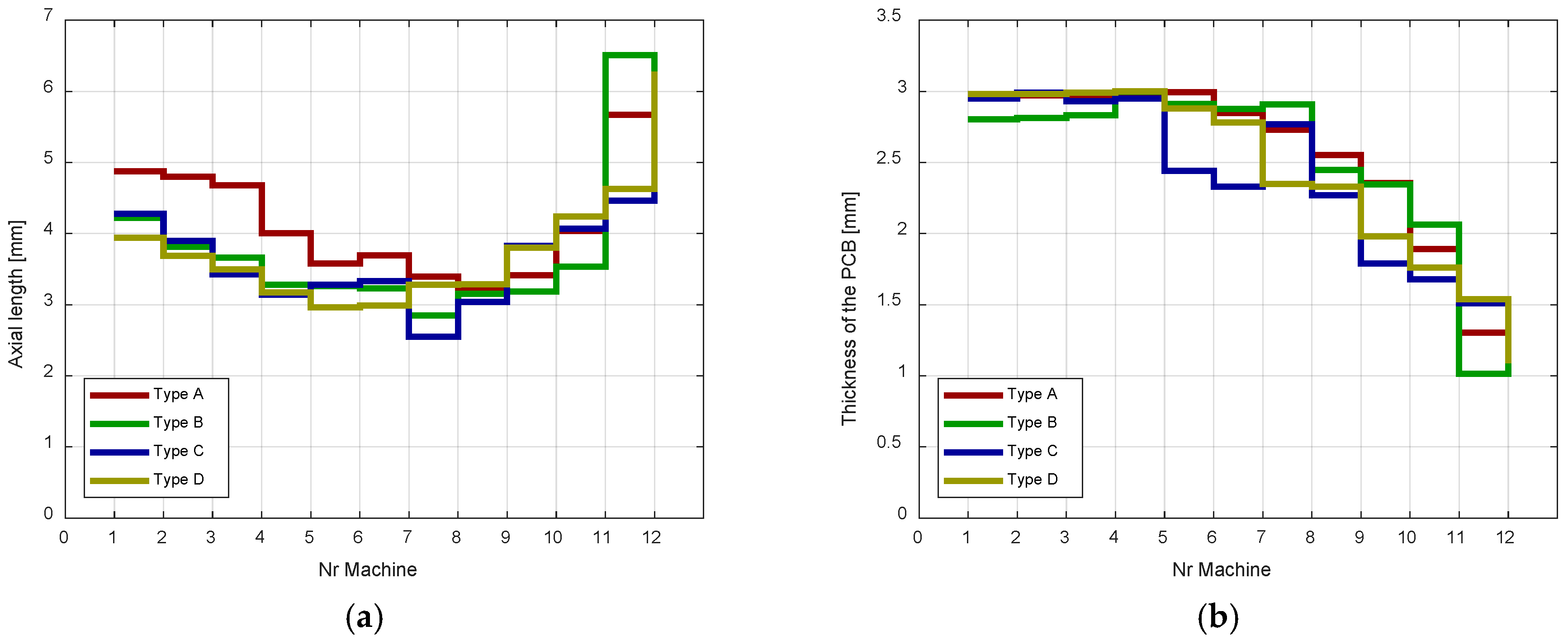
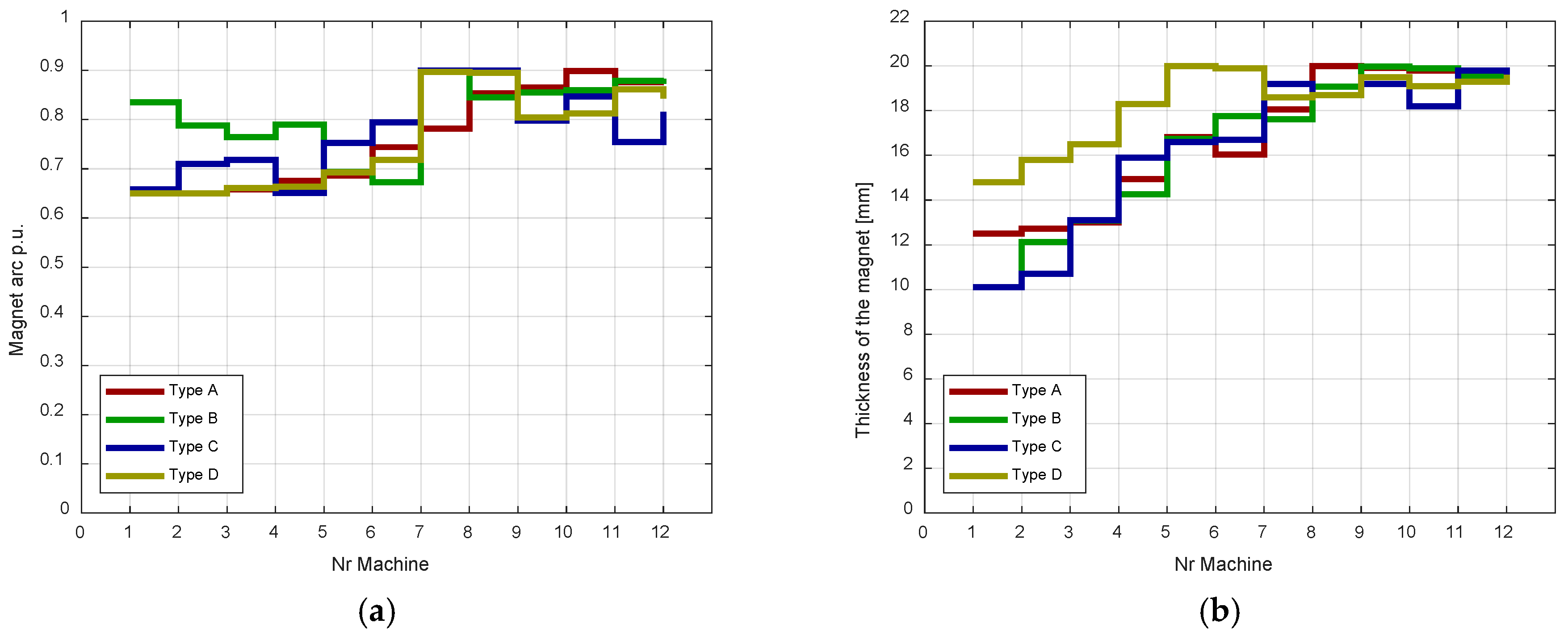
- Type A: machine with non-magnetic material for both stator and rotor yokes (ironless machine);
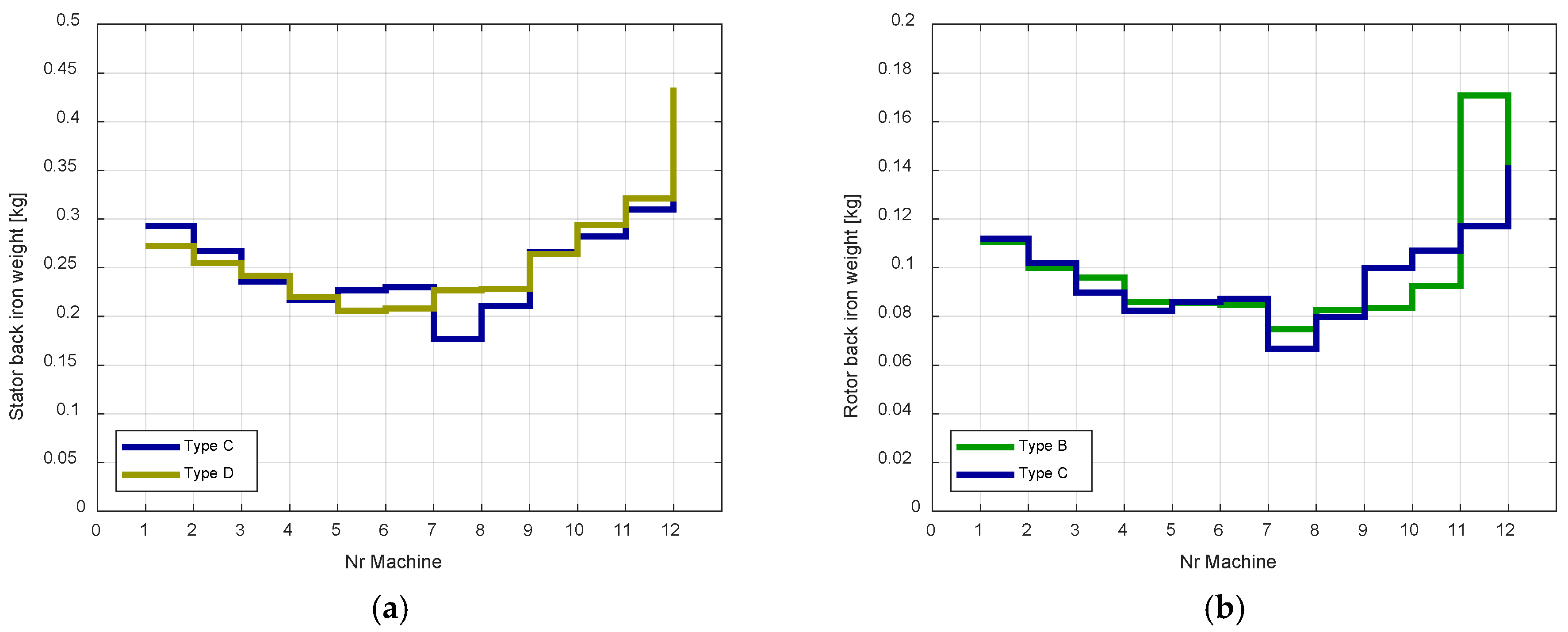
- Type B: machine with non-magnetic material for the stator yoke and ferromagnetic material (M-19 29 Ga) for the rotor yoke;
- Type C: machine with ferromagnetic material (M-19 29 Ga) for both stator and rotor yokes; and,
- Type D: machine with non-magnetic material for the rotor yoke and ferromagnetic material (M-19 29 Ga) for the stator yoke.
5.1. Comparison
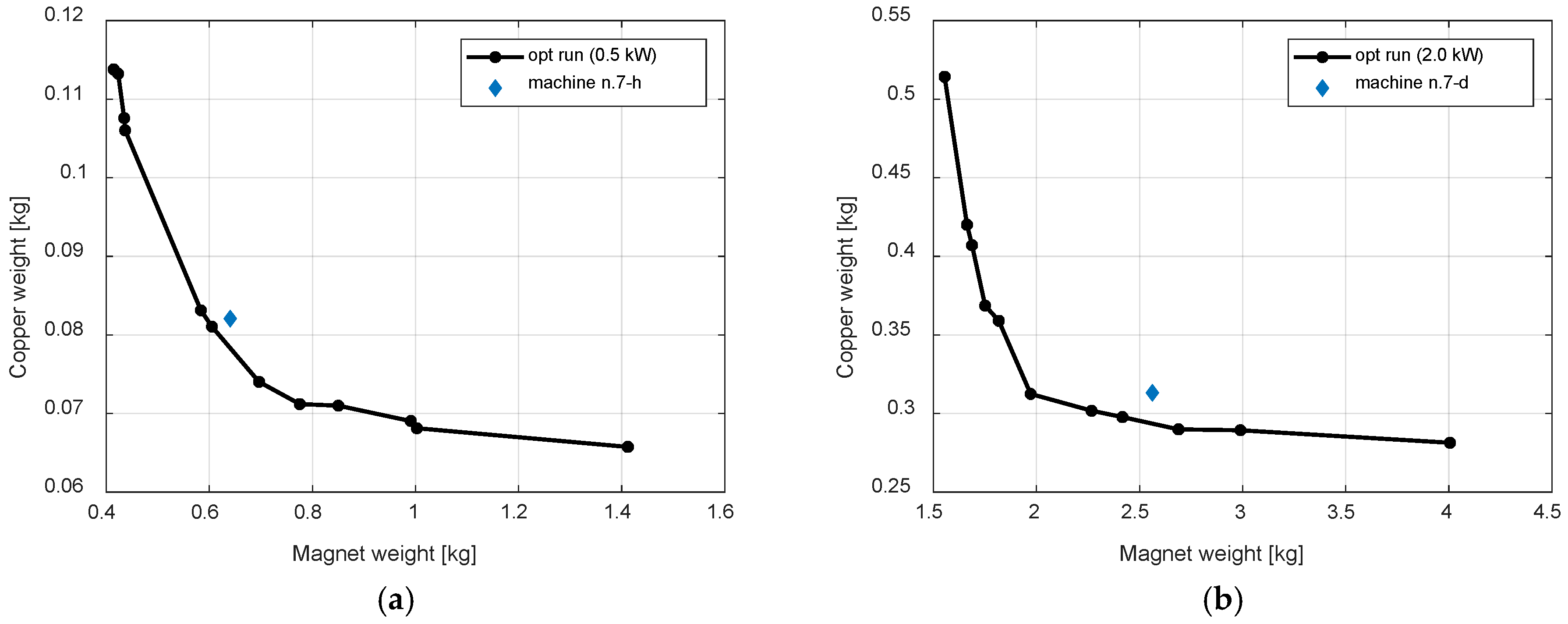
5.2. Scalability
6. Conclusions
Author Contributions
Funding
Acknowledgments
Conflicts of Interest
Nomenclature
| Symbols | |
| A | Wind turbine rotor swept area |
| C | Rotor circumference |
| CP | Power coefficient |
| D | Rotor diameter |
| F | Force at airgap |
| iSdq | Stator current in the dq-reference frame |
| L | Axial length |
| P | Output power |
| R | Rotor radius |
| T | Output torque |
| λ | Tip Speed Ratio |
| λdq | Flux linkage in the dq-reference frame |
| ρ | Air density |
| RS | Stator resistance |
| Ttarget | Target torque |
| va | Wind speed upstream the streamtube |
| vp | Wind speed at the rotor |
| vO | Wind speed downstream the streamtube |
| vSdq | Stator voltage in the dq-reference frame |
| ω | Rotational speed |
| Acronyms | |
| CP | Combined Population |
| CFD | Computational Fluid Dynamic |
| DAWT | Diffuser-Augmented Wind Turbines |
| DC | Direct Current |
| DL | Double Layer |
| FE | Finite Element |
| FEA | Finite Element Analysis |
| FEMM | Finite Element Method Magnetics |
| NSGA | Nondominated Sorting Genetic Algorithm |
| PCB | Printed Circuit Board |
| PM | Permanent Magnet |
| p.u. | Per Unit |
| S-HAWT | Shrouded Horizontal Axis Wind Turbines |
| SL | Single Layer |
References
- Wu, Y.K.; Tsai, C.Z.; Li, Y.H. Design of wind power generators: Summary and comparison. In Proceedings of the 2018 IEEE International Conference on Applied System Invention (ICASI), Chiba, Japan, 13–17 April 2018; pp. 1314–1317. [Google Scholar]
- Cuesta, A.B.; Gomez-Gil, F.J.; Fraile, J.V.M.; Rodríguez, J.A.; Calvo, J.R.; Vara, J.P. Feasibility of a Simple Small Wind Turbine with Variable-Speed Regulation Made of Commercial Components. Energies 2013, 6, 3373–3391. [Google Scholar] [CrossRef] [Green Version]
- Blaabjerg, F.; Liserre, M.; Ma, K. Power Electronics Converters for Wind Turbine Systems. IEEE Trans. Ind. Appl. 2012, 48, 708–719. [Google Scholar] [CrossRef]
- Stiebler, M. Wind Energy Systems for Electric Power Generation; Springer: Berlin/Heidelberg, Germany, 2008. [Google Scholar]
- Blaabjerg, F.; Ma, K. Wind Energy Systems. Proc. IEEE 2017, 105, 2116–2131. [Google Scholar] [CrossRef]
- Potgieter, J.H.J.; Kamper, M.J. Double PM-Rotor, Toothed, Toroidal-Winding Wind Generator: A Comparison with Conventional Winding Direct-Drive PM Wind Generators over a Wide Power Range. IEEE Trans. Ind. Appl. 2016, 52, 2881–2891. [Google Scholar] [CrossRef]
- Artal-Sevil, J.S.; Dufo, R.; Domínguez, J.A.; Bernal-Agustín, J.L. Small wind turbines in smart grids. Transformation of electrical machines in permanent magnet synchronous generators. In Proceedings of the 2018 Thirteenth International Conference on Ecological Vehicles and Renewable Energies (EVER), Monte-Carlo, Monaco, 10–12 April 2018; pp. 1–8. [Google Scholar]
- Zeinali, R.; Ertan, H.B.; Yamali, C.; Tarvirdilu-Asl, R. Magnetically geared direct drive wind generator thermal analysis. In Proceedings of the 2017 International Conference on Optimization of Electrical and Electronic Equipment (OPTIM) & 2017 International Aegean Conference on Electrical Machines and Power Electronics (ACEMP), Brasov, Romania, 25–27 May 2017; pp. 462–469. [Google Scholar]
- Polinder, H.; van der Pijl, F.F.A.; de Vilder, G.J.; Tavner, P.J. Comparison of direct-drive and geared generator concepts for wind turbines. IEEE Trans. Energy Convers. 2006, 21, 725–733. [Google Scholar] [CrossRef]
- Li, H.; Chen, Z. Overview of different wind generator systems and their comparisons. IET Renew. Power Gener. 2008, 2, 123–138. [Google Scholar] [CrossRef]
- Baroudi, J.A.; Dinavahi, V.; Knight, A.M. A review of power converter topologies for wind generators. Renew. Energy 2007, 32, 2369–2385. [Google Scholar] [CrossRef]
- Yuan, T.; Yang, N.; Zhang, W.; Cao, W.; Xing, N.; Tan, Z.; Li, G. Improved Synchronous Machine Rotor Design for the Easy Assembly of Excitation Coils Based on Surrogate Optimization. Energies 2018, 11, 1311. [Google Scholar] [CrossRef]
- Higuchi, T.; Yokoi, Y.; Abe, T.; Sakimura, K. Design Analysis of a Novel Synchronous Generator for Wind Power Generation. Machines 2014, 2, 202–218. [Google Scholar] [CrossRef] [Green Version]
- Stamenkovic, I.; Milivojevic, N.; Schofield, N.; Krishnamurthy, M.; Emadi, A. Design, Analysis, and Optimization of Ironless Stator Permanent Magnet Machines. IEEE Trans. Power Electron. 2013, 28, 2527–2538. [Google Scholar] [CrossRef]
- Stegmann, J.A.; Kamper, M.J. Design Aspects of Double-Sided Rotor Radial Flux Air-Cored Permanent-Magnet Wind Generator. IEEE Trans. Ind. Appl. 2011, 47, 767–778. [Google Scholar] [CrossRef]
- Peng, G.; Wei, J.; Shi, Y.; Shao, Z.; Jian, L. A Novel Transverse Flux Permanent Magnet Disk Wind Power Generator with H-Shaped Stator Cores. Energies 2018, 11, 810. [Google Scholar] [CrossRef]
- Jamali Arand, S.; Ardebili, M. Multi-objective design and prototyping of a low cogging torque axial-flux PM generator with segmented stator for small-scale direct-drive wind turbines. IET Electr. Power Appl. 2016, 10, 889–899. [Google Scholar] [CrossRef]
- IPC-2221. Generic Standard for Printed Wiring Boards. Available online: http://shop.ipc.org/IPC-2221B-English-P (accessed on 21 September 2018).
- Cupertino, F.; Ettorre, S. Torque production capabilities of electrical machines with planar windings. In Proceedings of the 38th Annual Conference on IEEE Industrial Electronics Society (IECON 2012), Montreal, QC, Canada, 25–28 October 2012; pp. 2080–2085. [Google Scholar]
- Yan, G.J.; Hsu, L.Y.; Wang, J.H.; Tsai, M.C.; Wu, X.Y. Axial-Flux Permanent Magnet Brushless Motor for Slim Vortex Pumps. IEEE Trans. Magn. 2009, 45, 4732–4735. [Google Scholar] [CrossRef]
- Moury, S.; Iqbal, M.T. A permanent magnet generator with PCB stator for low speed marine current applications. In Proceedings of the 2009 1st International Conference on the Developments in Renewable Energy Technology (ICDRET), Dhaka, Bangladesh, 17–19 December 2009; pp. 1–4. [Google Scholar]
- Hsu, L.Y.; Yan, G.J.; Tsai, M.C. Novel flexible printed circuit windings for slotless linear motor design. In Proceedings of the 2010 International Conference on Electrical Machines and Systems, Incheon, Korea, 10–13 October 2010; pp. 1578–1582. [Google Scholar]
- Ustun, O.; Tuncay, R.N. Design, analysis, and control of a novel linear actuator. IEEE Trans. Ind. Appl. 2006, 42, 1007–1013. [Google Scholar] [CrossRef]
- Hu, J.-F.; Wang, W.-X. Upgrading a Shrouded Wind Turbine with a Self-Adaptive Flanged Diffuser. Energies 2015, 8, 5319–5337. [Google Scholar] [CrossRef] [Green Version]
- Ohya, Y.; Karasudani, T. A shrouded wind turbine generating high output power with wind-lens technology. Energies 2010, 3, 634–649. [Google Scholar] [CrossRef]
- Khamlaj, T.A.; Rumpfkeil, M.P. Theoretical analysis of shrouded horizontal axis wind turbines. Energies 2017, 10, 38. [Google Scholar] [CrossRef]
- Werkle, M.J.; Presz, W.M., Jr. Ducted wind/water turbines and propellers revisited. J. Propuls. Power 2008, 24, 1146–1150. [Google Scholar] [CrossRef]
- Torresi, M.; Postiglione, N.; Filianoti, P.F.; Fortunato, B.; Camporeale, S.M. Design of a ducted wind turbine for offshore floating platforms. Wind Eng. 2016, 40, 468–474. [Google Scholar] [CrossRef]
- Deb, K.; Pratap, A.; Agarwal, S.; Meyarivan, T. A fast and elitist multiobjective genetic algorithm: NSGA-II. IEEE Trans. Evol. Comput. 2002, 6, 182–197. [Google Scholar] [CrossRef] [Green Version]
- Meeker, D.C. Finite Element Method Magnetics, Version 4.2. Available online: http://www.femm.info (accessed on 3 May 2017).
- Meeker, D.; Bianchi, N.; Gyselinck, J.; Sabariego, R.V.; Alberti, L.; Pellegrino, G.; Cupertino, F. Electrical machine analysis using free software. In Proceedings of the 2017 IEEE Energy Conversion Congress and Exposition (ECCE), Cincinnati, OH, USA, 1–5 October 2017; pp. 1–289. [Google Scholar]
- Fatemi, A.; Ionel, D.M.; Demerdash, N.A.O.; Nehl, T.W. Fast Multi-Objective CMODE-Type Optimization of PM Machines Using Multicore Desktop Computers. IEEE Trans. Ind. Appl. 2016, 52, 2941–2950. [Google Scholar] [CrossRef]
- Cupertino, F.; Pellegrino, G.; Gerada, C. Design of Synchronous Reluctance Motors with Multiobjective Optimization Algorithms. IEEE Trans. Ind. Appl. 2014, 50, 3617–3627. [Google Scholar] [CrossRef]
- Di Nardo, M.; Galea, M.; Gerada, C.; Palmieri, M.; Cupertino, F. Multi-physics optimization strategies for high speed synchronous reluctance machines. In Proceedings of the 2015 IEEE Energy Conversion Congress and Exposition (ECCE), Montreal, QC, Canada, 20–24 September 2015; pp. 2813–2820. [Google Scholar]
- Rosu, M.; Zhou, P.; Lin, D.; Ionel, D.M.; Popescu, M.; Blaabjerg, F.; Rallabandi, V.; Staton, D. Automated Optimization for Electric Machines. In Multiphysics Simulation by Design for Electrical Machines, Power Electronics and Drives; Wiley-IEEE Press: Hoboken, NJ, USA, 2018; Volume 1, p. 312. [Google Scholar]
- Cupertino, F.; Palmieri, M.; Pellegrino, G. Design of high-speed synchronous reluctance machines. In Proceedings of the 2015 IEEE Energy Conversion Congress and Exposition (ECCE), Montreal, QC, Canada, 20–24 September 2015; pp. 4828–4834. [Google Scholar]
- Cupertino, F.; Leuzzi, R.; Monopoli, V.G.; Cascella, G.L. Maximisation of power density in permanent magnet machines with the aid of optimisation algorithms. IET Electr. Power Appl. 2018, 12, 1067–1074. [Google Scholar] [CrossRef]
- Duan, Y.; Ionel, D.M. A Review of Recent Developments in Electrical Machine Design Optimization Methods with a Permanent-Magnet Synchronous Motor Benchmark Study. IEEE Trans. Ind. Appl. 2013, 49, 1268–1275. [Google Scholar] [CrossRef]
- Goldberg, D.E. Genetic Algorithms in Search, Optimization, and Machine Learning, 1st ed.; Addison-Wesley: Boston, MA, USA, 1989; ISBN 0201157675. [Google Scholar]


| Parameter | Lower Bound | Upper Bound | Unit |
|---|---|---|---|
| Magnet arc | 0.65 | 0.9 | p.u. |
| Magnet thickness | 10 | 20 | mm |
| PCB thickness | 1 | 3 | mm |
| Parameter | N.7-Type A | N.7-Type C |
|---|---|---|
| Power [kW] | 1 | 1 |
| Electromagnetic torque [Nm] | 14.4 | 14.4 |
| Copper weight [kg] | 0.19 | 0.15 |
| Magnet weight [kg] | 1.30 | 1.20 |
| Thickness of the magnet [mm] | 18.1 | 19.2 |
| Thickness of the PCB [mm] | 2.7 | 2.8 |
| Axial length [mm] | 3.4 | 2.6 |
| Magnet arc [p.u.] | 0.78 | 0.90 |
| Copper loss [W] | 15 | 11 |
| Iron loss [W] | 0 | 19 |
| Efficiency [%] | 98.5 | 97 |
| Parameter | Starting Machine | Half-Power Machine | Double-Power Machine |
|---|---|---|---|
| Target Power [kW] | 1 | 0.5 | 2 |
| Turbine diameter [mm] | 1440 | 1020 | 2040 |
| Rotational speed [rpm] | 663 | 937 | 468 |
| Target torque [Nm] | 14.4 | 5.1 | 40.8 |
| Generator axial length [mm] | 2.6 | 1.9 | 3.7 |
| Copper weight [kg] | 0.15 | 0.08 | 0.31 |
| Magnet weight [kg] | 1.20 | 0.64 | 2.55 |
© 2018 by the authors. Licensee MDPI, Basel, Switzerland. This article is an open access article distributed under the terms and conditions of the Creative Commons Attribution (CC BY) license (http://creativecommons.org/licenses/by/4.0/).
Share and Cite
Palmieri, M.; Bozzella, S.; Cascella, G.L.; Bronzini, M.; Torresi, M.; Cupertino, F. Wind Micro-Turbine Networks for Urban Areas: Optimal Design and Power Scalability of Permanent Magnet Generators. Energies 2018, 11, 2759. https://doi.org/10.3390/en11102759
Palmieri M, Bozzella S, Cascella GL, Bronzini M, Torresi M, Cupertino F. Wind Micro-Turbine Networks for Urban Areas: Optimal Design and Power Scalability of Permanent Magnet Generators. Energies. 2018; 11(10):2759. https://doi.org/10.3390/en11102759
Chicago/Turabian StylePalmieri, Marco, Salvatore Bozzella, Giuseppe Leonardo Cascella, Marco Bronzini, Marco Torresi, and Francesco Cupertino. 2018. "Wind Micro-Turbine Networks for Urban Areas: Optimal Design and Power Scalability of Permanent Magnet Generators" Energies 11, no. 10: 2759. https://doi.org/10.3390/en11102759