Sensorless Energy Conservation Control for Permanent Magnet Synchronous Motors Based on a Novel Hybrid Observer Applied in Coal Conveyer Systems


College of Instrumentation Science and Optoelectronics Engineering, Beijing University of Aeronautics and Astronautics, Beijing 100191, China
*
Author to whom correspondence should be addressed.
Energies 2018, 11(10), 2554; https://doi.org/10.3390/en11102554
Submission received: 31 August 2018
/
Revised: 20 September 2018
/
Accepted: 22 September 2018
/
Published: 25 September 2018
(This article belongs to the Section F: Electrical Engineering)
Abstract
:A large number of permanent magnet synchronous motors (PMSMs) are used to drive coal conveyer belts in coal enterprises. Sensorless energy conservation control has important economic value for these enterprises. The key problem of sensorless energy conservation control for PMSMs is how to decompose the stator current through estimating the rotor position and speed accurately. Then a double closed loop control for stator current and speed is formed to make the stator current drive the motor as an entire torque current. In this paper, the proposed startup estimation algorithm can utilize the current model of PMSM as reference model to estimate the rotor speed and position in the startup stages. It is not dependent on the back electromotive force (EMF) which is used by the general estimation algorithm. However, the resistance will change with the temperature shift of stator windings, and these changes will cause the reference current model to be inaccurate and influence the rotor speed and position estimation precision. Thus, startup estimation algorithm switches to the proposed operation estimation algorithm which is based on the robust sliding mode theory and is not dependent on the motor parameters. The advantages of startup estimation algorithm and operation estimation algorithm are combined to form a hybrid observer. This hybrid observer realizes the accurate estimation of the rotor speed and position from start-up to operation. The stator current is precisely decomposed. The excitation current is controlled to 0. Meanwhile, the double closed-loop control of current and speed is achieved. The stator current is as entire torque current to drive motor. The closed-loop control, which is based on the proposed rotor position and speed estimation algorithm, achieve the most efficient conversion of electrical energy.
1. Introduction
The permanent magnet synchronous motor (PMSM) is widely applied in industrial fields, such as electric vehicles, elevators, and other high-power transmission systems [1,2] because of its high power factor and high energy density. In a coal mine enterprise, are a large number of PMSMs are used to drive coal conveyer belts. The PMSM that drives the coal conveyer belt often starts and operates with a full load of coal. With the general driven method for PMSM, the current of PMSM needs to exceed the 50% rated current to meet the torque requirement with a full load coal. In other words, it takes the 1.5 times the rated current to produce the rated torque by the normal method, and 50% of the energy is wasted. This will seriously affect the economic benefits of the coal enterprise.
Some literatures [3,4,5,6] have studied how to increase the torque and reduce the torque ripple, but their feedback about rotor position and speed are measured by speed or position sensors. In order to adapt to the harsh working environment in coal mine such as abundant dust and high humidity, the drive motor is controlled without position and speed sensors to ensure the stability and reliability of the transmission system. The high speed performance of PMSMs is improved by designing and optimizing the rotor structure in [7], but if the control performance of PMSMs is low, the structural improvement of high speed performance will be limited.
In order to ensure the high control performance of PMSMs, a double closed loop control for stator current and speed is adopted to make the stator current drive the motor as an entire torque current. Thus, the current must be decomposed accurately. The key of current decomposition is to estimate the rotor position and speed accurately and form a double closed loop control. The estimated rotor position can decompose the stator current into torque current and excitation current accurately, meanwhile, the excitation current is controlled to 0. The estimated rotor speed can be fed back to the closed-loop control of speed.
The speed and rotor position estimation methods are divided into several categories. At present, the estimation method based on back-electromotive force (EMF) is widely studied [8,9,10,11,12,13]. On examining these references, the speed and rotor position are estimated by innovative algorithms based on the back-EMF signals. However, in the startup stage, the speed is very low and the back-EMF is not induced effectively. Therefore, in the start-up stage, the back-EMF signal is weak and easily disturbed. The accuracy of the estimation algorithm based on back-EMF will be greatly influenced by this weak and disturbed back-EMF in this startup stage.
To solve the problem that the back-EMF cannot be utilized to estimate the speed and rotor position in the stage of start-up, in [14,15,16,17,18,19,20], the rotor position and speed are estimated by the signal injection method. Many other injection signals are selected for sensorless control of PMSM. They include pseudo-random high-frequency square-wave voltage injection [14], square-wave signal injection [15], carrier signal injection [16], HF test current injection [17] and high-frequency signal injection [18]. However, these injection signals are superimposed on the normal drive signal to excite the motor. Therefore, these special injected signals will cause the fluctuation of the electromagnetic torque easily.
In [21], the sliding mode control is applied to improve the performance of sensorless PMSMs. However, the focus of this article is on high speed control of PMSMs. The PMSM in this paper needs to be adjusted from low speed to high speed. Under low speed, the phenomenon of chattering in sliding mode theory will lead to a larger rotor position and speed estimation error.
A research on nonlinear control for PMSMs was done by [22]. This back-stepping technique is very effective in improving the performance of the PMSM, but the speed feedback in back-stepping technique needs to be measured by an encoder. In order to adapt to the harsh working environment in coal mines such as abundant dust and high humidity, the PMSM in this paper needs to adopt the sensorless control mode without encoder.
In a previous work [23], an improved phase-locked loop is used to estimate the position and speed of sensorless PMSMs only at high speed too. The rotor position is estimated by variations of inductances in [24], but the identification excitation signals, which are injected into the motor to identify the inductance when the motor runs, easily cause control signal distortion at high speed. A study on estimation for rotor speed and position was done by [25] according to a novel zero-sequence model. Previous work, such as [26], deals only with the estimation of rotor speed and position based on the back-EMF model. The approach taken by [27] is model predictive control for sensorless drive of PMSMs. The predictive model is derived by the state equation of PMSM in the - two-phase stationary coordinate system. A paper relevant to estimation for rotor speed and position was published by [28]. In this reference, an extended flux model is used to estimate rotor speed and position. Both the PMSM state equation and all kinds of standard models of PMSM depend on the motor parameters. The estimation error easily increases when the standard models change because of the variations of PMSM parameters.
In [29,30], although the torque and flux linkage of PMSM can be controlled under variable parameters, the control method of these references is applied to low-power PMSMs. In addition, the online parameter identification [31,32,33,34] can also solve this problem. The details on parameter identification are discussed in [35], where the results of parameter identification are imbedded into an intelligent drive algorithm to correct the PMSM model in real time. However, the combination of the online identification algorithm and the estimation algorithm will greatly take up the calculation resources of the DSP. This will lead to the poor real-time performance of the controller. The research reported in reference [36] focuses on an accelerated algorithm for parameter identification, but this algorithm requires additional processor and hardware support. Considering that the stator resistance will change with the temperature shift of the motor stator windings, there is a functional relationship between resistance and temperature. Some studies on temperature estimation of stator winding are discussed in [37,38], but the function relationship between temperature and stator resistance is too complex. The stator resistance cannot be estimated accurately by using the temperature in real time.
In order to ensure that the rotor speed and position can be accurately estimated from startup to operation, in this paper, aiming at the problem that the estimation error for rotor speed and position is large because of the weak back-EMF in the startup stage, a startup estimation algorithm which is based on current model of PM motor and independent on the back-EMF signal is proposed. Aiming at the problem that the estimation error for rotor speed and position is large because the variation of resistance can cause an inaccurate reference current model of the PMSM in the operation stage, an operation estimation algorithm which is based on the robust sliding mode theory and is not dependent on the motor parameters, is proposed. Meanwhile, the inaccurate estimation of the operation estimation algorithm in the startup stage can be compensated by the startup estimation algorithm. The two algorithms form a hybrid observation algorithm to ensure the stable and reliable operation. According to the accurate estimation for rotor position and speed, a closed-loop system is implemented. The stator current is controlled as the whole torque current to drive the motor, and the energy consumption of PMSM is greatly saved. Meanwhile, the influence of current on rotor flux is eliminated, and the electromagnetic torque is more stable. The out of step situation for PMSMs because of the unstable electromagnetic torque has been avoided. The PMSM starts directly, and its reliability has been improved greatly.
In the Materials and Methods section, the principle of energy conservation during startup and operation of a PMSM and the general method for starting and controlling the PMSM are introduced. The theoretical analysis and algorithm design of proposed start-up estimation algorithm and operation estimation algorithm are given. In the Results (Section 3), the PMSM experimental platform is described. On this experimental platform, the proposed algorithm is verified according to the experiment results. In Section 4, the obtained results and how these results can be perceived in perspective of previous studies that have tackled similar problems are discussed. Finally, the conclusions are drawn in the final Conclusions section.
2. Materials and Methods
2.1. Principle of Energy Conservation in Startup and Operation of PMSM
Because the energy of the PMSM is essentially reflected by the current, the efficiency of controlling PMSM energy conversion is actually the efficiency of controlling current work. As shown in Figure 1, the current space vector is composed by , and in stator windings. can be decomposed into a component which is oriented to the direction of rotor flux and a component which is orthogonal to the direction of rotor flux . The electromagnetic torque is generated by the rotor flux an . It can be expressed as a formula , where, is a constant. Meanwhile, the will generate the increasing magnetic effect or the weakened magnetic effect for the rotor flux . If generates the weak magnetic effect for the rotor flux , then this part of the current will be equivalent to counteract the torque effect which is generated by the torque current. This part of energy which plays a negative role is a huge waste. If generates the increasing magnetic effect for the rotor flux , since the magnetization point of the rotor is generally designed near the saturation region of the magnetization curve, increasing magnetic by current will lead the magnetization point of the rotor into saturation region of magnetization curve. It means that even if the current increases, the flux will not increase again. This part of the current is also wasted. When the motor starts, the phenomenon that the motor current is large but the output torque is small often occurs. The reason is that a large part of the stator current does some useless work, and the actual torque current component is small. Thus, we have to increase the amplitude of to increase the torque current, but with this method, the excitation current is also greatly increased, it results in a great waste of energy. The emphasis of this paper is to reduce the starting current from three times or even five times rated current to the rated current, meanwhile, the starting torque is not reduced. It means that the entire stator current is controlled to produce torque. The efficiency of energy conversion is greatly improved.
2.2. The General Method for Sensorless Starting and Controlling PMSM
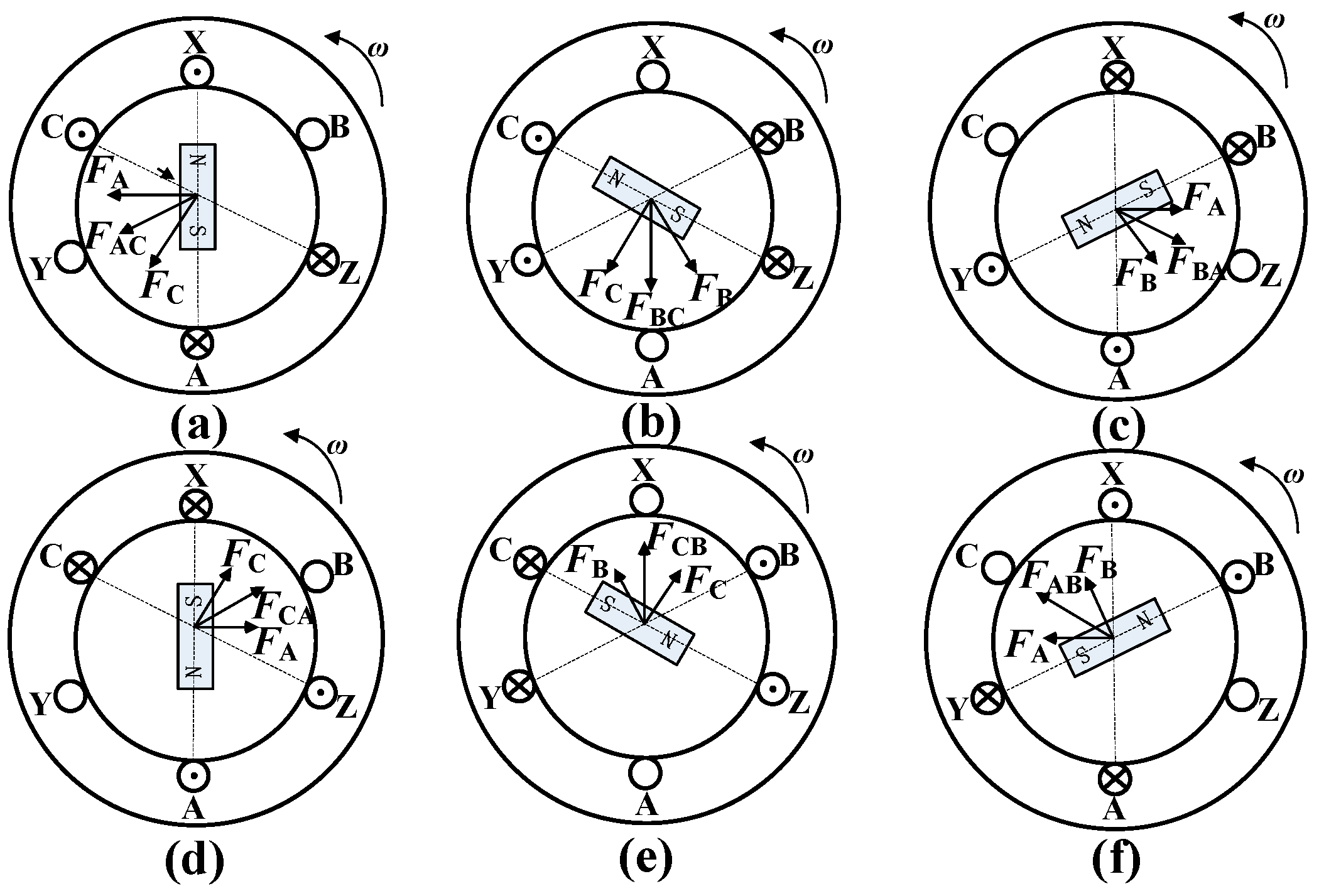
The rotational conduction of two-phase stator windings is adopted as the general senseless drive method for PMSM. When phase-b is disconnected, while phase-a and phase-c are connected in series, the flux generated by current in phase-a is FA. The flux generated by current in phase-c is FC. The synthetic flux of FA and FC is FAC, which is oriented to Y. Similarly, the next moment, as shown in Figure 2b, phase-a is disconnected while phase-b and phase-c is connected in series. The synthetic flux of FB and FC is FBC, which is oriented to A. In this way, there are six combinations because of the two phase conduction in the three-phase stator windings. These six combinations make the space flux to rotate around the stator space, as shown in Figure 2c–f. Electromagnetic torque produced by interaction of space flux and rotor flux drives the rotor to rotate. This general drive method is reliable, but the rotor needs to be dragged to the given position to determine the switch order before starting the PMSM. A large DC current needs to be provided before startup to drag the rotor to the given position. With this method, when the PMSM connects with a heavy load, the current of driving rotor needs to be very large. It is easy to cause the over-current fault in the inverter. In addition, because the synthetic flux has only six directions, the component of the synthetic flux along the rotor direction is not 0. This part of the non-zero flux, which is produced by the current along the rotor direction, is not involved in the formation of the electromagnetic torque. Therefore, this part of the current will be wasted completely.
2.3. The Double Closed-Loop Startup and Control Method for PMSM Based on Hybrid Observer
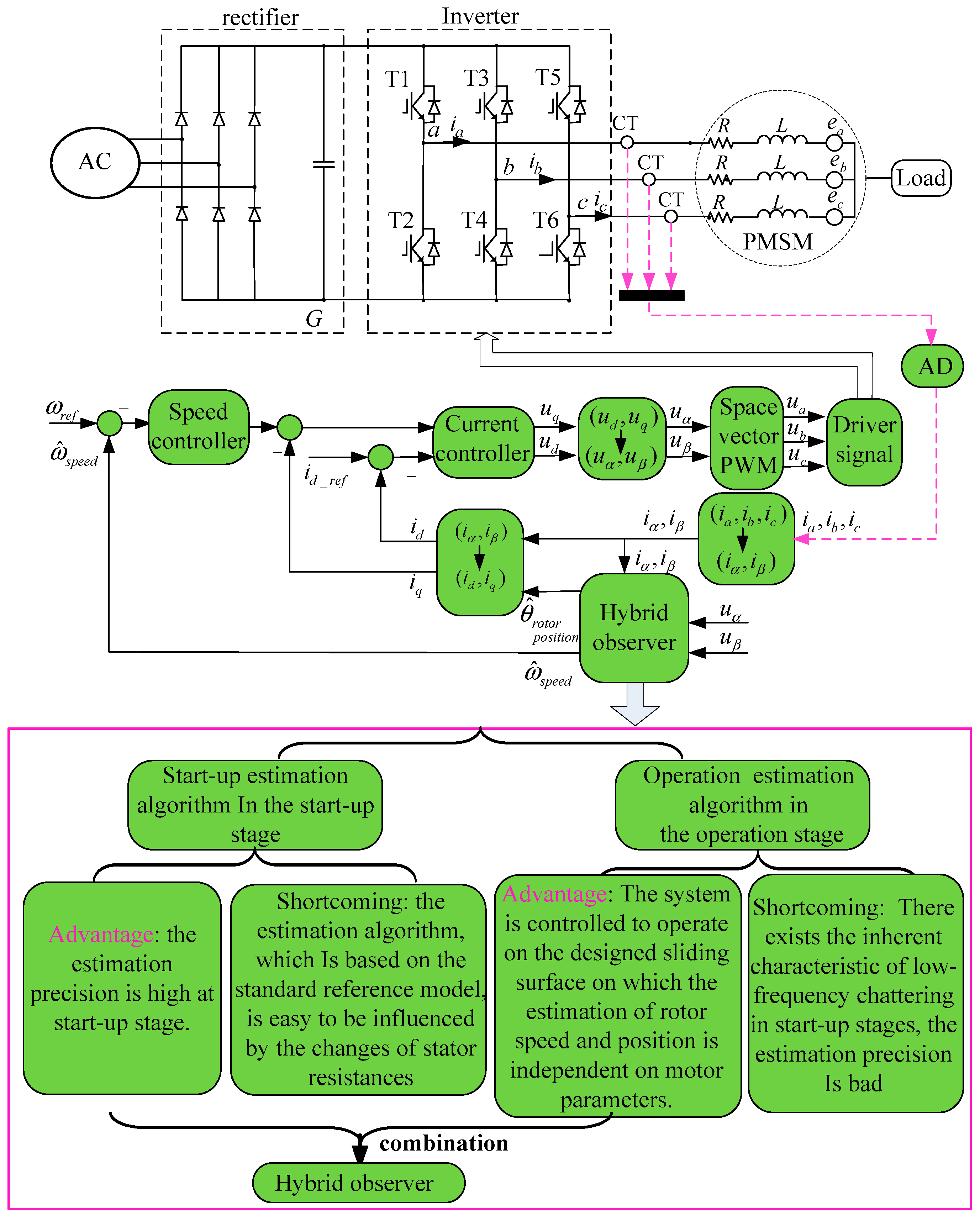
Figure 3 shows the principle of sensorless double closed-loop control and the hybrid observer design scheme. The key of double closed loop control is the accurate estimation of rotor speed and position. By this hybrid observer, the rotor position can be estimated accurately. If the rotor position is estimated accurately, the space current vector can be decomposed into the component current whose direction is along the rotor flux and the other component current whose direction is perpendicular to the rotor flux. The current component whose direction is along the rotor flux direction is controlled to 0. Thus, the space current vector can be controlled to be orthogonal with the rotor flux. The enough electromagnetic torque can be produced.
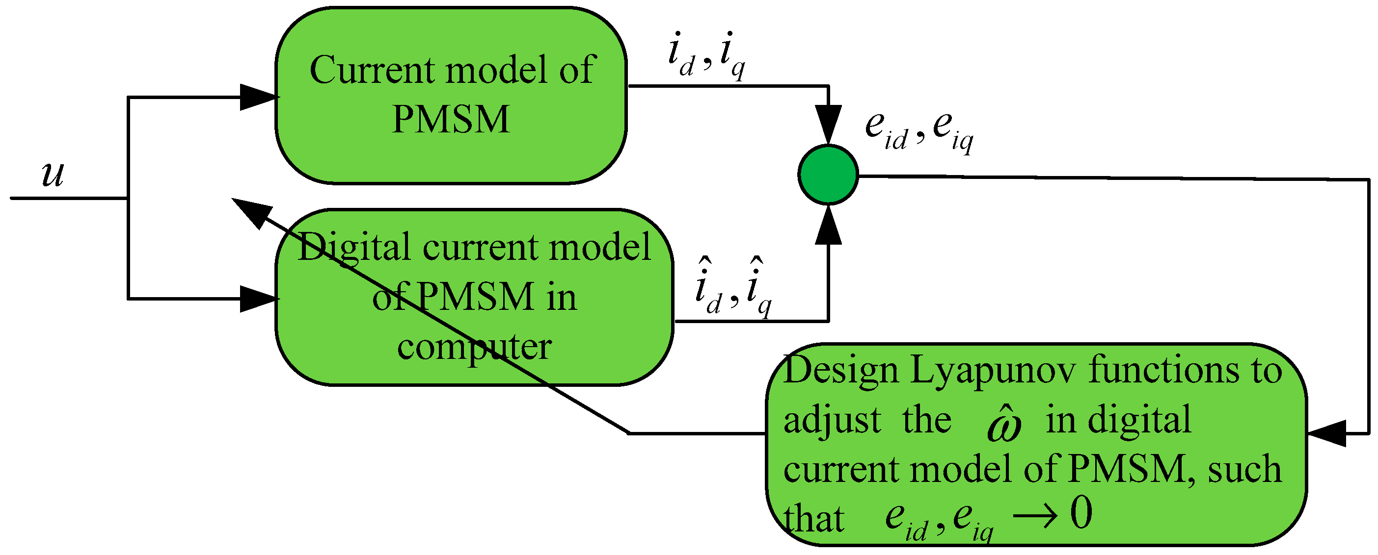
The hybrid observer consists of start-up estimation algorithm and operation estimation algorithm. In the start-up algorithm, the Lyapunov function is designed to estimate the rotor speed and position according to the PMSM current model. The startup estimation algorithm doesn’t depend on the back-EMF when the motor starts, however, it depends on the motor parameters. When the PMSM outputs power, the resistance of the PMSM will change with the temperature shift of the stator winding. These changes can cause the reference current model to be inaccurate and lead to inaccurate estimation for rotor speed and position. In this case, the start-up estimation algorithm switches to the operation estimation algorithm which is independent on motor parameters when the motor is running for a period of time.
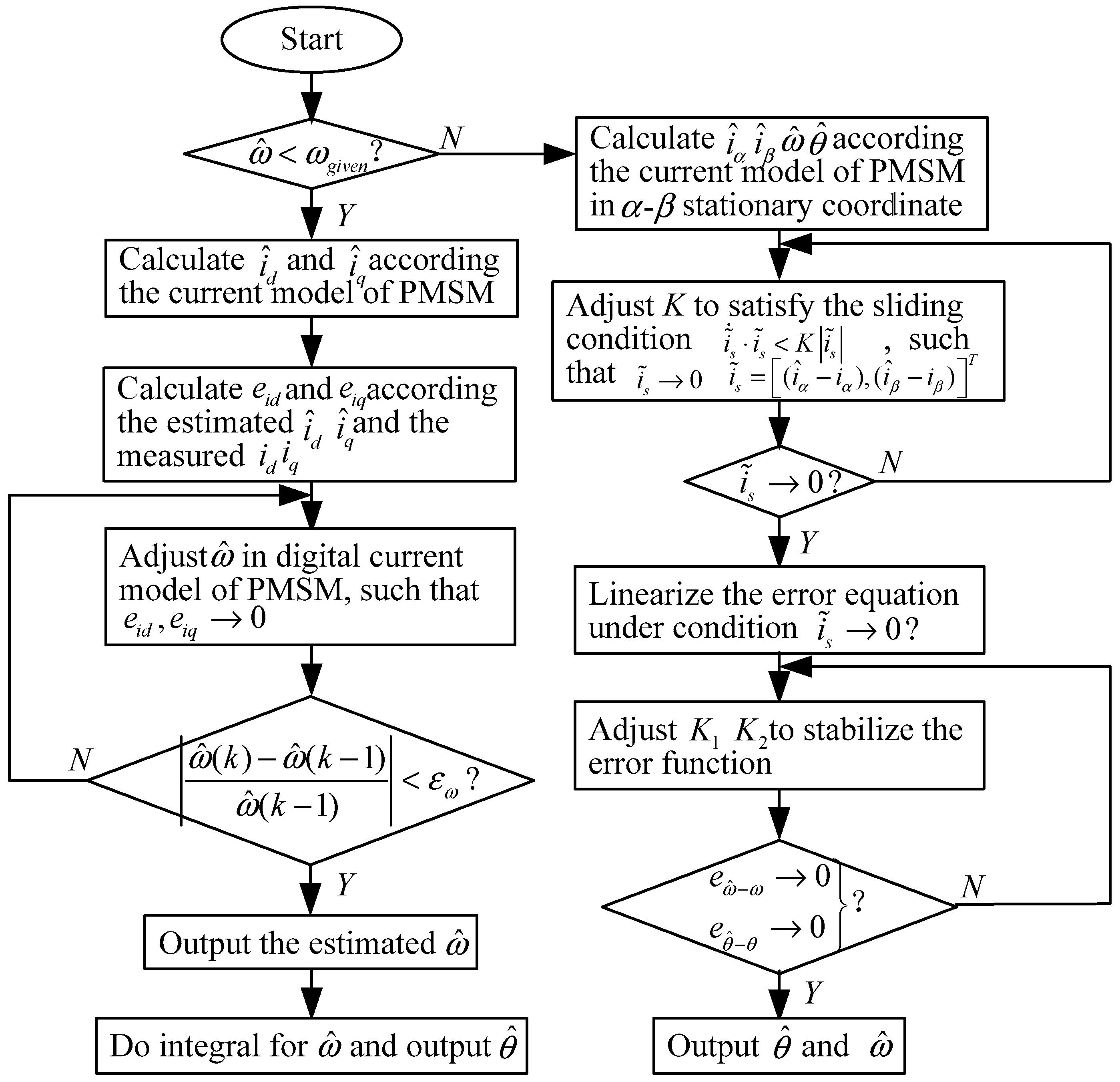
In this proposed operation estimation algorithm, the system is controlled to operate on the designed sliding surface on which the estimation of rotor speed and position is independent on motor parameters. The speed and rotor position can be estimated accurately. Figure 4 shows a flowchart of the hybrid observer. The advantages of the two algorithms are combined to form a hybrid observation algorithm. When , it means that the PMSM is in the startup stage and the back-EMF has not been effectively induced, the estimation algorithm based reference current model is adopted. When , it means that the PMSM is in the operation stage and the back-EMF has been induced, the estimation algorithm is switched to the operation estimation algorithm.
2.4. The Derivation of the Voltage Equation of PMSM in - Two-Phase Stationary Coordinate System and - Two-Phase Rotation Coordinate System
As shown in Figure 5, space vector can be represented in the -- three-phase coordinate system, and it also can be represented in the - coordinate system as follows:
where, the coefficient is used to guarantee the equal-vector transformation.
Whether in a three-phase coordinate system or in a two-phase coordinate system, the space voltage vector equation of the PMSM can be expressed as follows:
Because the rotor of PMSM in this paper is surface-mounted, the air gap between the rotor and the stator is uniform, the phase inductance and resistance are symmetrical. In addition, the space flux vector is composed of the stator flux vector which is generated by three phase currents and rotor flux vector . Therefore, the following equation can be obtained:
As shown in the Figure 5, the rotor flux vector can be represented as follows:
where, represents the amplitude of the rotor flux vector and represents the angle of the rotor flux vector.
Substituting Equations (3) and (4) into Equation (2), we can get:
Since:
Substituting Equations (6), (7) and (8) into Equation (5), meanwhile, sorting out the equation, we can get:
This is the voltage equation of PMSM in the - two-phase stationary coordinate system. The transformation of PMSM equation from - two-phase stationary coordinate system to the d-q two-phase rotation coordinate system is called the Park transformation. The transformation relationship of voltage and current is as follows:
Substituting Equations (10) and (11) into Equation (9), we can get:
Since:
Sorting out Equation (12), we can get:
This is the voltage equation of PMSM under the d-q two-phase rotation coordinate system.
The motion equations of PMSM are as follows:
where, the electromagnetic torque equation is:
in addition, is the load torque; is number of poles; is the moment of inertia; is the viscous friction coefficient; is the angle between the current vector and the rotor flux.
As shown in Figure 5, the in (16) is actually the component of the current vector on the d axis. Therefore, the can be represented by and as follows:
Substituting Equations (16) and (17) into Equation (15), meanwhile, sorting out the equation, we can get:
Combining Equations (9), (18) and (19), we can obtain the state equation of PMSM in - two-phase stationary coordinate system:
2.5. Theoretical Analysis of Start-Up Estimation Algorithm
According to Equation (14), the state equation of the PMSM in the rotating coordinate system can be described as:
Assume that , , ,
Equation (21) can be converted to the following form:
The estimated equation can be obtained according to Equation (22):
The error equation between the estimated equation and physical equation of PMSM can be obtained by implementing these two equations subtraction operations Equation (23)–Equation (22).
Let:
The error equation can be expressed as follows:
The Lyapunov function can be designed as follows:
The differential of can be expressed as:
Since , if , then . Substituting Equation (26) into Equation (28) and according to Equations (24) and (25), we can get:
Simplify Equation (29), and define , we can obtain:
From Equation (30), the relationship between the differential of speed error and the current can be obtained:
Substituting Equation (31) into Equation (30), we can get:
The integral of Equation (31) can be written as:
where, represents the error between the estimated speed and the real speed. When the motor starts, , , The first estimation for speed after startup is this error . The second estimation for speed is as follows: . By analogy, the estimate speed of the next moment can be obtained according to the error. Meanwhile, the rotor position can be obtained by integral of the speed . Figure 6 shows the diagrammatic scheme of startup estimation algorithm for rotor speed and position.
2.6. Theoretical Analysis of Operation Observer Algorithm
According to Equation (20), the state equation of PMSM in - two-phase stationary coordinate system can be regarded as a nonlinear system:
where .
In Equation (34), the state variable can be divided into two parts, one part of the state variable is which can be measured. The other part of state variable is which is needed to be estimated by the designed observer.
The easily measured state variables and can be defined as:
The needed to be estimated state variables can be defined as:
Equation (34) can be written as follows:
where according to Equation (20):
According to the description of state equation of PMSM, a digital model can be constructed in the processor. The input of the digital model is equal to the actual input of motor. The state variables in the digital model are the estimation quantities of the state variables of the PMSM.
The digital model of PMSM in processor can be expressed as:
where , and .
Since:
the following equation can be obtained:
The idea is that the error equation between the estimated equation and physical equation of PMSM can be obtained by implementing two subtraction operation Equation (41)–Equation (37) and Equation (42)–Equation (38). The error equation can be expressed as follows:
where:
If the state variables in the error state equations converge to 0, we can consider that the estimation values of the state variables have converged to the real values. Therefore, by comparing the measurable and the outputs of the operation estimation algorithm, the system is controlled on the designed sliding surface on which the estimation of rotor speed and position is independent on motor stator resistance.
In Equations (45) and (46), and respectively are expanded as the Taylor series near , and the high orders polynomial above 2-order are ignored. The linearized equation of state equation can be obtained:
where:
where:
Thus, Equations (45) and (46) can be written as:
Since can be measured, can be known. To design sliding surface and to control the system operating on this sliding surface, the following condition must be satisfied:
where:
Thus, if:
then:
We can get:
Substituting Equation (66) into Equation (57), we can get:
where:
Substituting Equation (66) into Equation (58), we can get:
Substituting Equation (67) into Equation (69), and eliminating , we can get:
Therefore, the equation can be stabilized as long as the eigenvalues of the matrix are assigned to the negative real part.
Thus, . Then it can be considered that the estimation values for rotor position and speed converge to the real value.
The following is the pole assignment for the equation .
We can achieve the stabilization for the Equation (70) by designing .
Since:
If we design , , such that:
then:
has characteristic roots with the negative real. Finally, the stabilization of the equation is accomplished.
Considering:
Then, contains the factor:
such that:
Meanwhile, existing L such that:
Therefore, we can get:
From the above analysis, it can be seen that the gain matrices and are determined by choosing , , and the expression form of Equation (72) can be obtained, thus the poles of the matrix are assigned to the negative real part. Finally, the target that error state Equation (70) converges to 0 is achieved. It means that , the estimation of the speed and rotor position converge to the real value. Figure 7 represents the diagrammatic scheme of operation estimation algorithm for the rotor speed and position.
3. Results
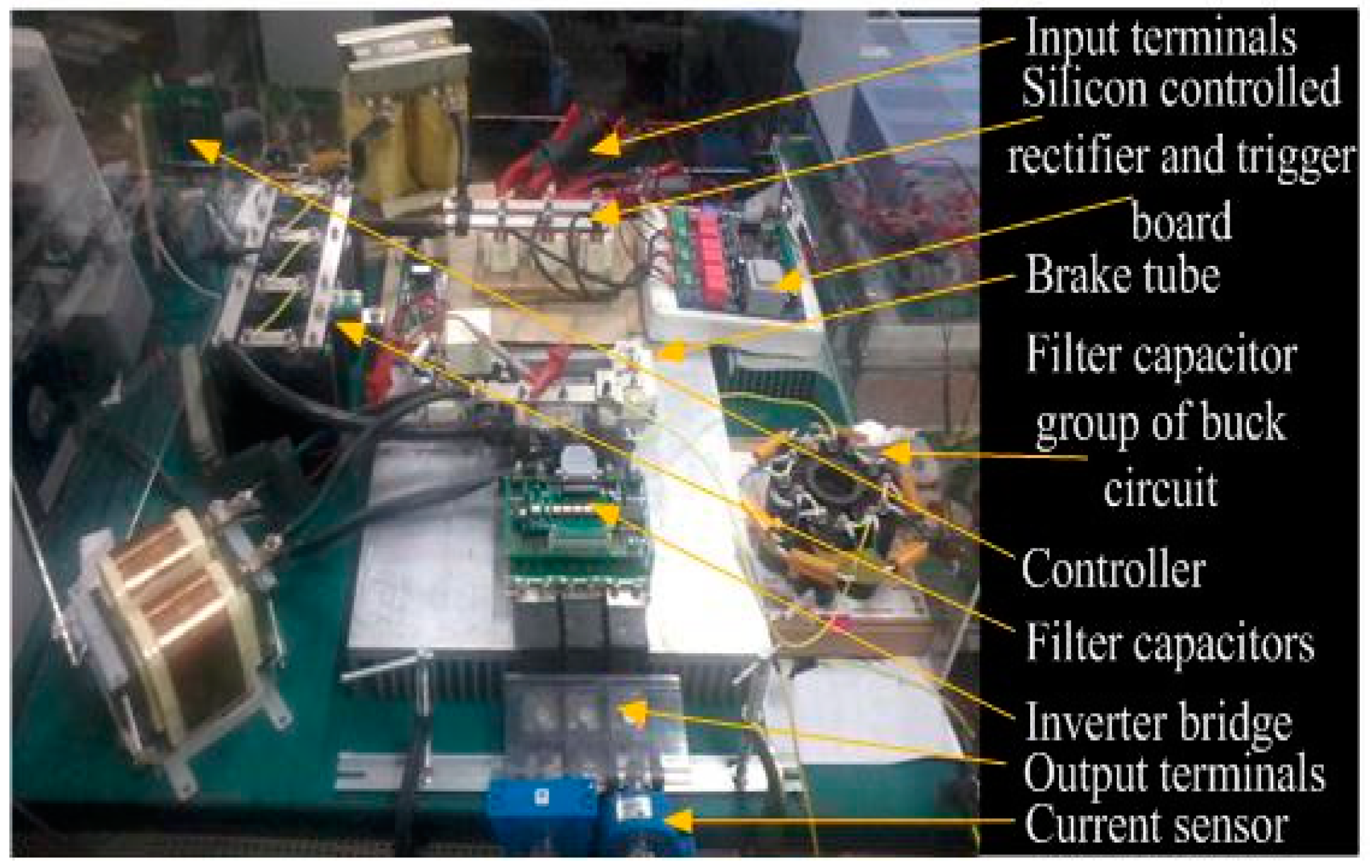
3.1. Introduction of the Experiment Platform
The proposed estimation algorithm of hybrid observer has been successfully implemented on the experimental platform shown in Figure 8. The experimental platform consists of the control system and the experimental motors. As shown in Figure 9, the experimental motors consist of the PMSM and the load generator. While the PMSM starts, the load generator will power on and produce the reversed electromagnetic torque as the load.
The estimation algorithms are digitally implemented with the high speed Texas Instruments DSP (TMS320F28335), which is a new 32-bit floating-point DSP Controller provides 150 MHz CPU frequency, 18 PWM outputs, and so on- based control board. Full-controllable switching devices are adopted in the inverter. The double closed-loop method is adopted to control the PMSM. The inner loop of the double closed-loop is the current loop and the outer loop of the double-closed loop is the speed loop. The feedbacks of rotor speed and position are provided by proposed hybrid observer.
3.2. Description and Analysis of the Experimental Results
Firstly, define the three stages in Figure 10, Stage I: startup stages, Stage II: the stage of just reaching given speed, Stage III: the stage of operating for a period of time at given speed. Figure 10 shows the speed which is estimated by operation estimation algorithm and start-up estimation algorithm respectively and its error from stage I to stage III.
The middle of Figure 10b shows the speed estimated by start-up estimation algorithm from stage I to stage III. According to the start-up estimation algorithm, the Lyapunov function is designed to estimate rotor speed and position based on the current model of PMSM in the startup stages. As shown in the middle of Figure 10b, the start-up estimation algorithm which is designed according to the designed scheme in Figure 6 can achieve a good observation accuracy in stage I. The estimation error is only 1.4%. However, because the large current can make the stator winding heat and cause the stator resistance change, these changes will lead to an inaccurate reference model. The observation accuracy of start-up estimation algorithm has gradually decline. As shown in bottom of Figure 10b, the estimation error of the start-up estimation algorithm reaches to 2.96% in stage II. At the stage III, as shown in top of Figure 10b, the estimation error has reached to 5.52%. It can be predicted that with the motor continues running, the start-up estimation algorithm will gradually become invalid even not convergent.
Therefore, it is necessary to switch the operation estimation algorithm which is independent on motor parameters. Middle of Figure 10a shows the speed estimated by operation estimation algorithm from stage I to stage III. From middle of Figure 10a, it can be seen that the estimation accuracy of operation estimation algorithm is very poor in stage I because the inherent low frequency chattering on the sliding surface. The estimation error reaches 42%.
As shown in the bottom of Figure 10a, with the increase of the speed, the estimation error still reaches 4.72% in the stage II because the accumulated estimation error in startup stage is larger. With the increase of running time, the operation state of system on the sliding surface is more stable, and estimation error is smaller. As shown in top of Figure 10a, in stage III, the estimation error drops to 2.75%.
Longitudinal comparison for middle of Figure 10a, bottom of Figure 10a and top of Figure 10a, the estimation error of the operation estimation algorithm is from 42% to 4.72% then to 2.75% when the PMSM operates from stage I to stage II then to stage III. The estimation error is gradually reducing. It also shows that because of the inherent feature of low-frequency chattering for operation estimation algorithm, the operation estimation algorithm is not suitable in start-up stage.
Compared with the operation estimation algorithm, the estimation error of the start-up estimation algorithm is from 1.4% to 2.96% then to 5.52%, when the PMSM runs from stage I to stage II then to stage III. Correspondingly, the estimation error of the operation estimation algorithm is from 42% to 4.72% then to 2.75%, when the PMSM runs from stage I to stage II then to stage III. It can be concluded that the hybrid observer can well combine the advantages of the start-up estimation algorithm and operation estimation algorithm. The accurate speed estimation is achieved to guarantee closed-loop speed.
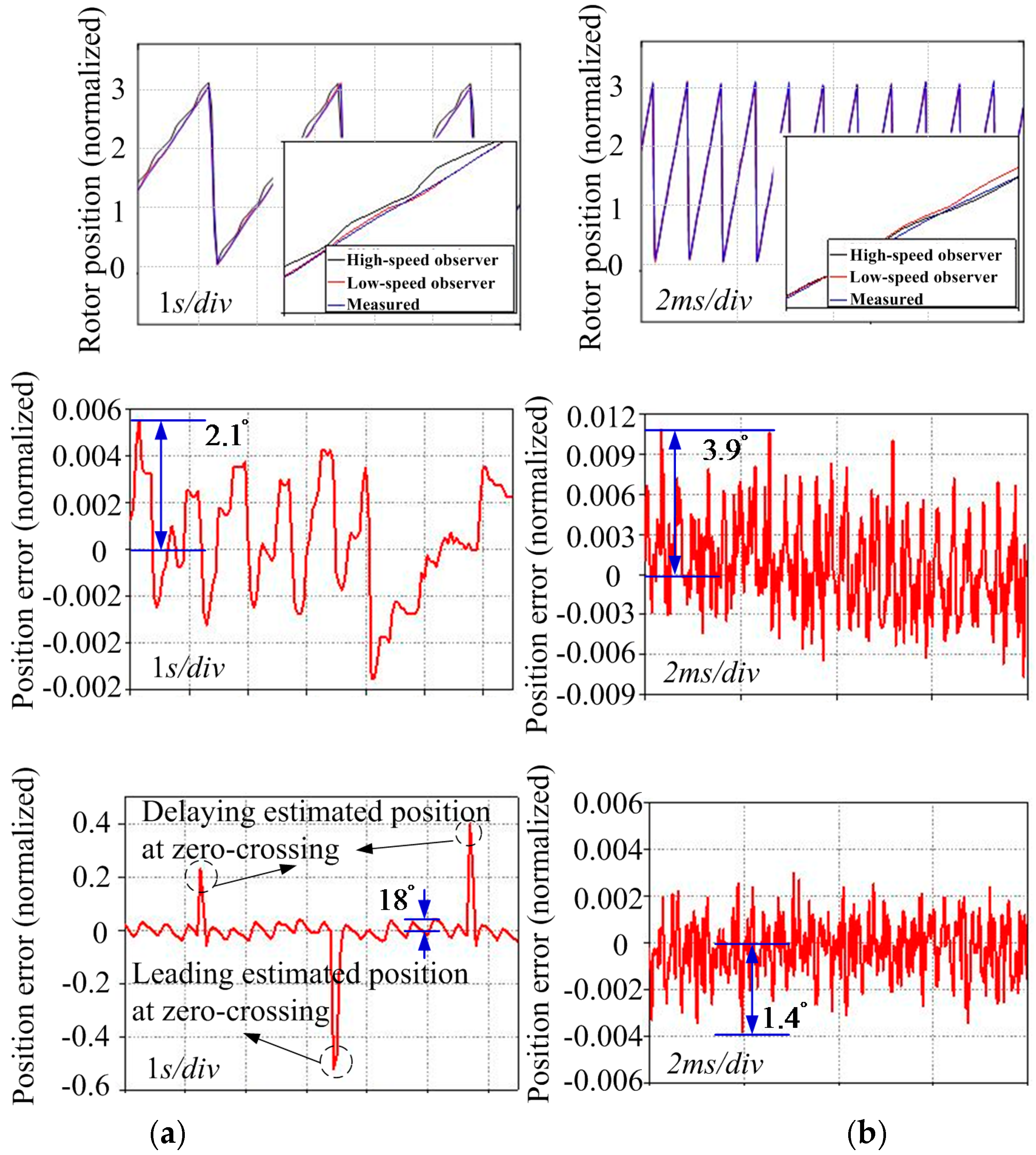
Figure 11 shows the rotor position, which is estimated by start-up estimation algorithm and operation estimation algorithm respectively, and its error from stage I to stage III. The top of Figure 11a represents the comparison between the measured rotor position and the rotor position estimated by the start-up estimation algorithm and the operation estimation algorithm in the startup stage. The middle of Figure 11a shows the error between the measured rotor position and the rotor position estimated by startup estimation algorithm in startup stage. The max error is . In contrast, as shown in the bottom of Figure 11a, in the startup stage, the rotor position estimated by operation estimation algorithm is not only inaccurate, with an error reaching , but phase delay at the zero crossing point also exists.
It can be concluded that the position observation precision of start-up estimation algorithm is higher than that of operation estimation algorithm in start-up stage. As shown in middle of Figure 11b, the estimation error of rotor position is increased from at startup stage to at a given speed. It shows that the estimation accuracy of the start-up estimation algorithm is getting worse. In contrast, although the estimation performance of the operation estimation algorithm is poor in the start-up stage, estimation precision of operation estimation algorithm is high at the operation stage. The estimation error of rotor position has been reduced to at the given speed. Correspondingly, as shown in the bottom of Figure 11a and the bottom of Figure 11b, the estimation error of the operation estimation algorithm for rotor position is from to .
It can be concluded that the hybrid observer can combine well the advantages of the start-up estimation algorithm and operation estimation algorithm. The rotor position estimation can be estimated accurately by this hybrid observer to guarantee the current decomposition.
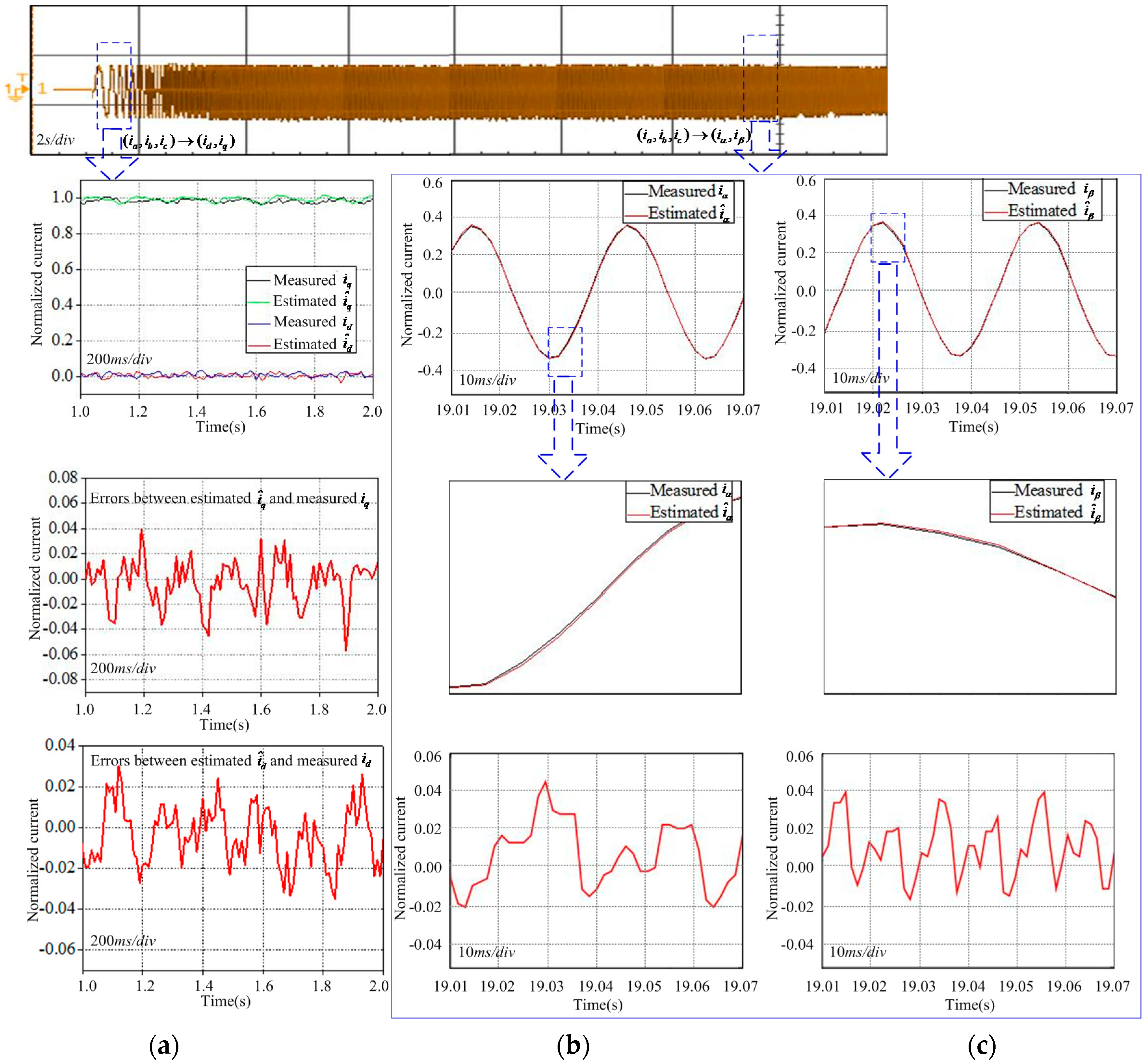
The top of Figure 12 represents the phase-current waveform when PMSM runs from start-up to given speed under the sensorless closed-loop control algorithm. According to the design scheme shown in Figure 6, the top of Figure 12a represents the and which are the real output of the motor and the and which are the estimation of the start-up estimation algorithm.
The middle of Figure 12a represents the error between the estimated by start-up estimation algorithm and the real measured current according to the design scheme shown in Figure 6. Correspondingly, the bottom of Figure 12a represents the error between the estimated by start-up estimation algorithm and the real measured current according to the design scheme shown in Figure 6. These errors correspond to the and in Equations (71) and (72). From Equation (23), it can be seen that the speed estimation can be adjusted to control the and which are the outputs of the start-up estimation algorithm. The error between the estimated current , and the measured current , is used to correct the speed estimation according to Equation (32). Finally, the outputs of the start-up estimation algorithm , can follow the measured , . As shown in the middle of Figure 12a and the bottom of Figure 12a, the error and are tiny.
This means that the speed estimation algorithm in start-up estimation algorithm makes the estimated currents and corresponding with the real measured currents and . Finally, the estimated speed tends to the actual speed. Figure 12b,c represent the comparison for the current and , which are estimated by operation estimation algorithm, and the measured current and , according to the design scheme shown in Figure 7. The bottom of Figure 12b represents the error between the estimated and the measured . The bottom of Figure 12c represents the error between the estimated and the measured . From Figure 12b,c, it can be seen that and which are estimated by operation estimation algorithm have follow the measured and . According to the design scheme shown in Figure 7, firstly, the experiment phenomenon that and follow and strictly show that the system has been controlled on the sliding surface on which the estimation of rotor speed and position is independent on motor parameters. Further, synthesized the experimental result shown in top of Figure 10a and bottom of Figure 11b, the state variables, which consist of the speed estimation error and rotor position estimation error, has converged to 0 by the pole placement. The accurate estimation for speed and rotor position has been achieved.
4. Discussion
From the above description and analysis for the experimental results, it can be seen that the proposed hybrid observer has solved several problems well. Firstly, the hybrid observer can accurately estimate the rotor speed and position from start-up to operation at a given speed. In the startup stage, the startup estimation algorithm in the hybrid observer works. As shown in the above-mentioned theoretical analysis of start-up estimation algorithm, the startup estimation algorithm can estimate the rotor speed and position accurately based on the current PMSM model without using the back-EMF information. Thus, the problem that the estimation error for rotor speed and position is large because of the weak back-EMF during the startup stage has been solved. As the PMSM continues to operate, the operation estimation algorithm in the hybrid observer begins to work. It means that the estimation algorithm for the rotor speed and position is switched from the start estimation algorithm to the operation estimation algorithm at this time. When the PMSM runs, the stator resistances will change because of the temperature variation of the stator windings. These changed stator resistances will lead to an inaccurate PMSM reference current model. Thus, the estimation error for rotor speed and position is large because of the inaccurate reference current model of PMSM in the operation stage. However, the operation estimation algorithm, which is based on the robust sliding mode theory and is not dependent on the motor parameters, can guarantee the accurate estimation for the rotor speed and position in the case of variable motor parameters.
From the experimental results of the startup estimation algorithm, it can be seen that the rotor speed and position estimation errors increase with the operation of the PMSM. Since the startup estimation algorithm is based on the standard reference model, the estimation accuracy of the start-up estimation algorithm is easily influenced by the resistance variation which is caused by the temperature shift of the stator windings. The speed estimation error reaches 4.72%, and the rotor position estimation error is when the PMSM has operated for a while. Accordingly, the operation estimation algorithm is based on sliding mode theory and has good robustness. At this time, the startup estimation algorithm switches to the operation estimation algorithm, which ensures the accurate estimation of the rotor speed and position at the operation stage.
From the experimental results of the operation estimation algorithm, it can be seen that although the estimation accuracy of the operation estimation algorithm is poor during the startup stage, with the running of the PMSM, it can estimate the rotor speed and position accurately because of the good robustness. Therefore, the advantages of the startup estimation algorithm and operation estimation algorithm are combined to form a hybrid observer. The rotor speed and position can be accurately estimated by this hybrid observer from the startup stage to the operation stage. The precise feedback of rotor position and speed ensures that the double closed-loop control shown in Figure 2 can be implemented well.
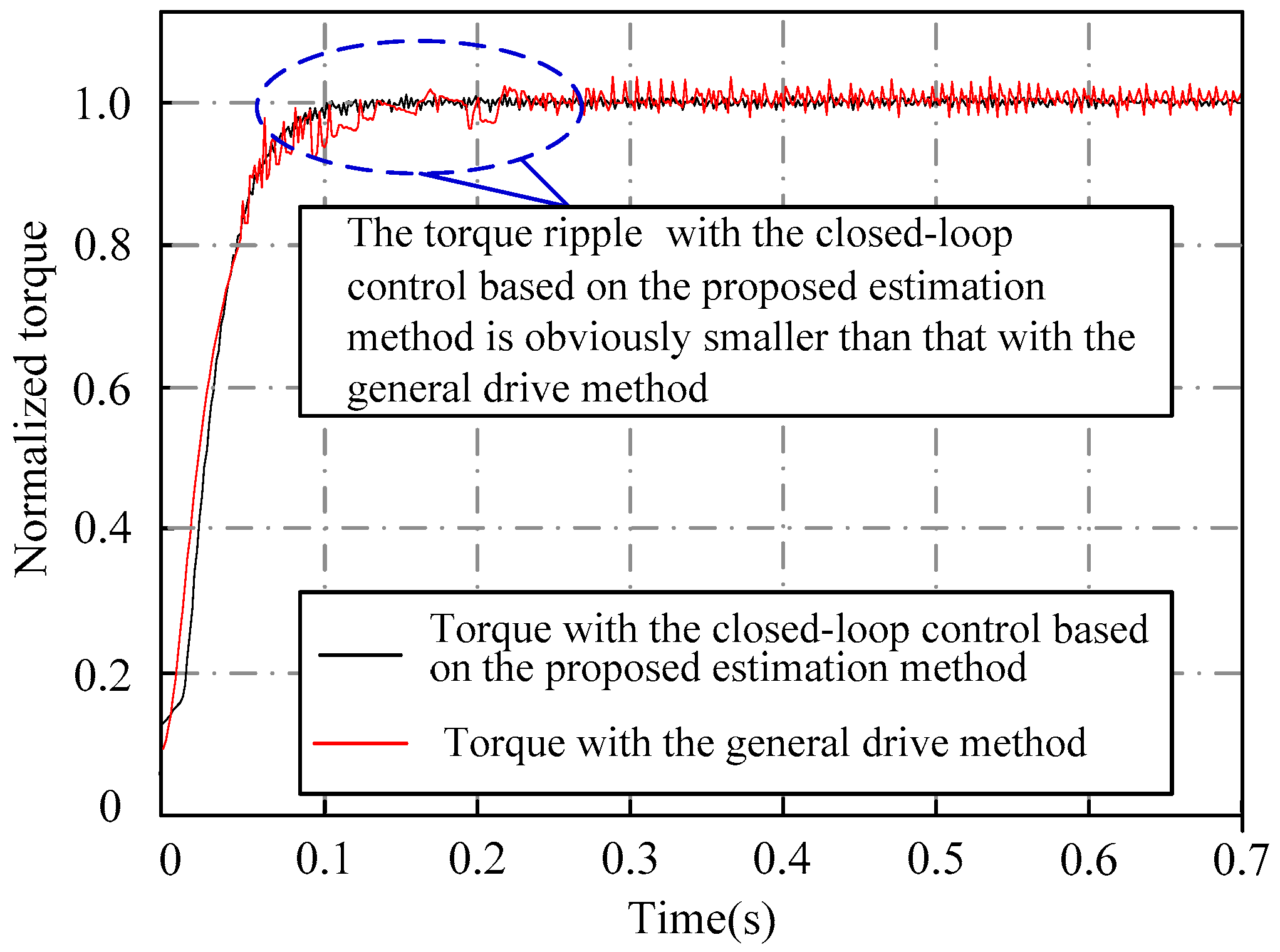
Secondly, as mentioned about the general PMSM control method, this general method has caused a lot of waste of electric energy. As shown in Figure 13, when the full load PMSM is driven by the general method, the driving current is about 1.5 times the rated current, but these 1.5 times the rated current only produce the rated torque shown in Figure 14. It can be seen that about 50% of the rated current is wasted, because the current along the rotor directions is not involved in the formation of the electromagnetic torque.
In this paper, the closed-loop control, which is based on the proposed rotor position and speed estimation algorithm, can control the current that is along the rotor direction to 0 in real time. In this method, the stator current is completely controlled as the torque current to drive the PMSM. The stator current is utilized with maximum efficiency. As shown in the top of Figure 12, when the full load PMSM is driven by the proposed method, the driving current is the rated current. The rated stator current drives the motor as the complete torque current, and this rated stator current generates rated torque is shown in Figure 14. In the case of generating the same torque, the closed-loop control based on the proposed rotor position and speed estimation algorithm, drives the full load PMSM with less than 50% of the rated current that the general method does. At the same time, because the current component along the rotor flux direction is controlled to 0 by closed-loop control based on the proposed rotor position and speed estimation algorithm, the flux produced by this current component will not increase or weaken the rotor flux. In contrast, with the general control method, a current component along the rotor flux direction exists. This current component will result in an enhancement or weakening effect on the rotor flux. Thus the electromagnetic torque will fluctuate. Figure 14 illustrates that the torque ripple generated by the general method is larger than that of the closed-loop method.
Moreover, the closed-loop system based on hybrid observer starts the PMSM without dragging the rotor to a given position. The problem that the PMSM is out of step because of the incorrect pre-positioning has been solved. The PMSM starts directly, and its reliability has been improved.
5. Conclusions
This paper proposes a startup estimation algorithm, which is based on a PMSM current model and is independent on the back-EMF signal, to estimate the rotor speed and position at the startup stage. With the operation of the PMSM, in order to avoid large estimation errors of the startup estimation algorithm because of the variable current model, the operation estimation algorithm, which is based on the robust sliding mode theory and is not dependent on the motor parameters, is proposed. The two algorithms form a hybrid observation algorithm to ensure the accurate estimation of rotor speed and position from startup to operation. Some validation experiments were done to verify the effectiveness of the proposed algorithm. One of the validation experiments is the comparison of current amplitudes when the PMSM starts and operates with the proposed algorithm and the general algorithm, respectively. This verification experiment shows that much more electrical energy can be conserved by the proposed method. Another validation experiment is the comparison of torque when the PMSM starts and operates with the proposed algorithm and the general algorithm, respectively. This verification experiment shows that torque ripple is less when using the proposed method, and with this method, a PMSM can be driven more reliably than with the general control method.
Author Contributions
This paper is the results of the hard work of all of the authors. S.L. conceived and designed the proposed method. S.L. and X.Z. conceived and analyzed the data; S.L. contributed to the reviewing of the document, and S.L. and X.Z. wrote the paper. All authors gave advice for the manuscript.
Funding
This work was supported by the National Natural Science Foundation of China under Grant 61721091, by the Civil Aerospace Advance Research Project, and by the National Natural Science Foundation of China under Grant 61873020.
Conflicts of Interest
The author declares no conflict of interest.
References
- Zhang, C.; Guo, Q.; Li, L. System Efficiency Improvement for Electric Vehicles Adopting a Permanent Magnet Synchronous Motor Direct Drive System. Energies 2017, 10, 2030. [Google Scholar] [CrossRef]
- Wang, G.; Xu, J.; Li, T.; Zhang, G.; Zhan, H.; Ding, L.; Xu, D. Weight-Transducerless Starting Torque Compensation of Gearless Permanent-Magnet Traction Machine for Direct-Drive Elevators. IEEE Trans. Ind. Electron. 2014, 61, 4594–4604. [Google Scholar] [CrossRef]
- Yu, L.; Zhang, Y.; Huang, W. Accurate and Efficient Torque Control of an Interior Permanent Magnet Synchronous Motor in Electric Vehicles Based on Hall-Effect Sensors. Energies 2017, 10, 410. [Google Scholar] [CrossRef]
- Feng, G.; Lai, C.; Kar, N.C. Practical Testing Solutions to Optimal Stator Harmonic Current Design for PMSM Torque Ripple Minimization Using Speed Harmonics. IEEE Trans. Power Electron. 2018, 33, 5181–5191. [Google Scholar] [CrossRef]
- Song, Q.; Li, Y.; Jia, C. A Novel Direct Torque Control Method Based on Asymmetric Boundary Layer Sliding Mode Control for PMSM. Energies 2018, 11, 657. [Google Scholar] [CrossRef]
- Liu, X.; Du, J.; Liang, D. Analysis and Speed Ripple Mitigation of a Space Vector Pulse Width Modulation-Based Permanent Magnet Synchronous Motor with a Particle Swarm Optimization Algorithm. Energies 2016, 9, 923. [Google Scholar] [CrossRef]
- Torrent, M.; Perat, J.I.; Jiménez, J.A. Permanent Magnet Synchronous Motor with Different Rotor Structures for Traction Motor in High Speed Trains. Energies 2018, 11, 1549. [Google Scholar] [CrossRef]
- Lin, T.C.; Zhu, Z.Q.; Liu, J.M. Improved Rotor Position Estimation in Sensorless-Controlled Permanent-Magnet Synchronous Machines Having Asymmetric-EMF With Harmonic Compensation. IEEE Trans. Ind. Electron. 2015, 62, 6131–6139. [Google Scholar] [CrossRef]
- Zhan, H.; Zhu, Z.Q.; Odavic, M. Nonparametric Sensorless Drive Method for Open-Winding PMSM Based on Zero-Sequence Back EMF With Circulating Current Suppression. IEEE Trans. Power Electron. 2017, 32, 3808–3817. [Google Scholar] [CrossRef]
- Song, J.; Kim, K. Practical Approach to Localize Simultaneous Triple Open-Switches for a PWM Inverter-Fed Permanent Magnet Synchronous Machine Drive System. Energies 2018, 11, 101. [Google Scholar] [CrossRef]
- Zhao, J.; Gu, Z.; Li, B.; Liu, X.; Li, X.; Chen, Z. Research on the Torque and Back EMF Performance of a High Speed PMSM Used for Flywheel Energy Storage. Energies 2015, 8, 2867–2888. [Google Scholar] [CrossRef] [Green Version]
- Jung, T.; Jang, J.H.; Park, C. A Back-EMF Estimation Error Compensation Method for Accurate Rotor Position Estimation of Surface Mounted Permanent Magnet Synchronous Motors. Energies 2017, 10, 1160. [Google Scholar] [CrossRef]
- Lin, F.-J.; Hung, Y.-C.; Chen, J.-M.; Yeh, C.-M. Sensorless IPMSM Drive System Using Saliency Back-EMF-Based Intelligent Torque Observer with MTPA Control. IEEE Trans. Ind. Inform. 2014, 10, 1226–1241. [Google Scholar]
- Wang, G.; Yang, L.; Yuan, B.; Wang, B.; Zhang, G.; Xu, D. Pseudo-Random High-Frequency Square-Wave Voltage Injection Based Sensorless Control of IPMSM Drives for Audible Noise Reduction. IEEE Trans. Ind. Electron. 2016, 63, 7423–7433. [Google Scholar] [CrossRef]
- Xu, P.L.; Zhu, Z.Q. Novel Square-Wave Signal Injection Method Using Zero-Sequence Voltage for Sensorless Control of PMSM Drives. IEEE Trans. Ind. Electron. 2016, 63, 7444–7454. [Google Scholar] [CrossRef]
- Xu, P.L.; Zhu, Z.Q. Carrier Signal Injection-Based Sensorless Control for Permanent-Magnet Synchronous Machine Drives Considering Machine Parameter Asymmetry. IEEE Trans. Ind. Electron. 2016, 63, 2813–2824. [Google Scholar] [CrossRef]
- Seilmeier, M.; Piepenbreier, B. Sensorless Control of PMSM for the Whole Speed Range Using Two-Degree-of-Freedom Current Control and HF Test Current Injection for Low-Speed Range. IEEE Trans. Power Electron. 2015, 30, 4394–4403. [Google Scholar] [CrossRef]
- Ramezani, M.; Ojo, O. The Modeling and Position-Sensorless Estimation Technique for A Nine-Phase Interior Permanent-Magnet Machine Using High-Frequency Injections. IEEE Trans. Ind. Appl. 2016, 52, 1555–1565. [Google Scholar]
- Lin, T.C.; Zhu, Z.Q. Sensorless Operation Capability of Surface-Mounted Permanent-Magnet Machine Based on High-Frequency Signal Injection Methods. IEEE Trans. Ind. Appl. 2015, 51, 2161–2171. [Google Scholar] [CrossRef]
- Chen, Z.; Gao, J.; Wang, F.; Ma, Z.; Zhang, Z.; Kennel, R. Sensorless Control for SPMSM With Concentrated Windings Using Multisignal Injection Method. IEEE Trans. Ind. Electron. 2014, 61, 6624–6634. [Google Scholar] [CrossRef]
- Wang, M.; Tsai, T. Sliding Mode and Neural Network Control of Sensorless PMSM Controlled System for Power Consumption and Performance Improvement. Energies 2017, 10, 1780. [Google Scholar] [CrossRef]
- Rahman, M.A.; Vilathgamuwa, D.M.; Uddin, M.N.; Tseng, K.J. Nonlinear control of interior permanent-magnet synchronous motor. IEEE Trans. Ind. Appl. 2003, 39, 408–416. [Google Scholar] [CrossRef] [Green Version]
- Chen, G.R.; Yang, S.C.; Hsu, Y.L.; Li, K. Position and Speed Estimation of Permanent Magnet Machine Sensorless Drive at High Speed Using an Improved Phase-Locked Loop. Energies 2017, 10, 1571. [Google Scholar] [CrossRef]
- Qiu, X.; Wang, W.; Yang, J.; Jiang, J.; Yang, J. Phase-Inductance-Based Position Estimation Method for Interior Permanent Magnet Synchronous Motors. Energies 2017, 10, 2002. [Google Scholar] [CrossRef]
- Zhan, H.; Zhu, Z.Q.; Odavic, M.; Li, Y. A Novel Zero-Sequence Model-Based Sensorless Method for Open-Winding PMSM With Common DC Bus. IEEE Trans. Ind. Electron. 2016, 63, 6777–6789. [Google Scholar] [CrossRef]
- Wang, G.; Li, T.; Zhang, G.; Gui, X.; Xu, D. Position Estimation Error Reduction Using Recursive-Least-Square Adaptive Filter for Model-Based Sensorless Interior Permanent-Magnet Synchronous Motor Drives. IEEE Trans. Ind. Electron. 2014, 61, 5115–5125. [Google Scholar] [CrossRef]
- Rovere, L.; Formentini, A.; Gaeta, A.; Zanchetta, P.; Marchesoni, M. Sensorless Finite-Control Set Model Predictive Control for IPMSM Drives. IEEE Trans. Ind. Electron. 2016, 63, 5921–5931. [Google Scholar] [CrossRef] [Green Version]
- Zhao, Y.; Zhang, Z.; Qiao, W.; Wu, L. An Extended Flux Model-Based Rotor Position Estimator for Sensorless Control of Salient-Pole Permanent-Magnet Synchronous Machines. IEEE Trans. Power Electron. 2015, 30, 4412–4422. [Google Scholar] [CrossRef]
- Lee, J.S. Stability Analysis of Deadbeat-Direct Torque and Flux Control for Permanent Magnet Synchronous Motor Drives with Respect to Parameter Variations. Energies 2018, 11, 2027. [Google Scholar] [CrossRef]
- Kim, Y.; Seo, H.T.; Kim, S.K.; Kim, K.S. A Robust Current Controller for Uncertain Permanent Magnet Synchronous Motors with a Performance Recovery Property for Electric Power Steering Applications. Energies 2018, 11, 1224. [Google Scholar] [CrossRef]
- Lai, C.; Feng, G.; Mukherjee, K.; Loukanov, V.; Kar, N.C. Torque Ripple Minimization for Interior PMSM with Consideration of Magnetic Saturation Incorporating Online Parameter Identification. IEEE Trans. Magn. 2017, 53, 1236. [Google Scholar] [CrossRef]
- Deng, W.; Xia, C.; Yan, Y.; Geng, Q.; Shi, T. Online Multiparameter Identification of Surface-Mounted PMSM Considering Inverter Disturbance Voltages. IEEE Trans. Energy Convers. 2017, 32, 202–212. [Google Scholar] [CrossRef]
- Zhang, J.; Hang, J.; Ding, S.; Cheng, M. Online Diagnosis and Localization of High-Resistance Connection in PMSM With Improved Fault Indicator. IEEE Trans. Power Electron. 2017, 32, 3585–3594. [Google Scholar] [CrossRef]
- Long, J.; Yang, M.; Lang, X.; Lv, X.; Liu, X.; Xu, D. Advanced online parameter identification-based PWM predictive control for AC servo systems. In Proceedings of the IECON 2016—42nd Annual Conference of the IEEE Industrial Electronics Society, Florence, Italy, 23–26 October 2016; pp. 2672–2677. [Google Scholar]
- Mercorelli, P. Parameters identification in a permanent magnet three-phase synchronous motor of a city-bus for an intelligent drive assistant. Int. J. Model. Identif. Control 2014, 21, 352–361. [Google Scholar] [CrossRef]
- Liu, Z.; Li, X.; Wu, L.; Zhou, S.; Liu, K. GPU-Accelerated Parallel Coevolutionary Algorithm for Parameters Identification and Temperature Monitoring in Permanent Magnet Synchronous Machines. IEEE Trans. Ind. Inform. 2015, 11, 1220–1230. [Google Scholar] [CrossRef]
- Cao, Z.; Li, W.; Zhang, X.; Fan, Y.; Zeng, J. Influence of Single Dual Ventilation Path on Fluid Field and Temperature Field of HVLSSR-PMSM with Air-Cooled Hybrid Ventilation Systems. Energies 2018, 11, 1343. [Google Scholar] [CrossRef]
- Jun, B.; Park, J.S.; Choi, J.H.; Lee, K.D.; Won, C.Y. Temperature Estimation of Stator Winding in Permanent Magnet Synchronous Motors Using d-Axis Current Injection. Energies 2018, 11, 2033. [Google Scholar] [CrossRef]
Figure 1.
Vector diagram about current decomposition based on initial rotor position.

Figure 2.
Schematic diagram of stator winding conduction and synthetic flux.

Figure 3.
Sensorless double closed-loop control and the design scheme of hybrid observer.

Figure 4.
The flowchart for the implementation of hybrid observer.

Figure 5.
Schematic diagram of winding relationship in different coordinate systems.
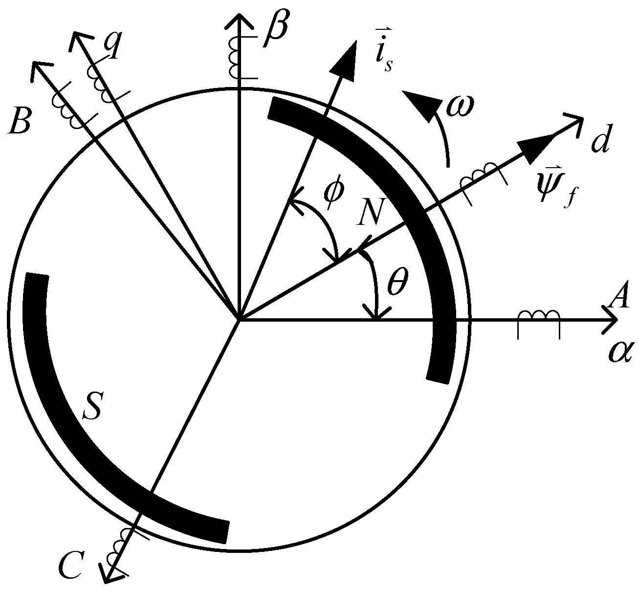
Figure 6.
Design scheme of start-up estimation algorithm.

Figure 7.
Design scheme of operation estimation algorithm.
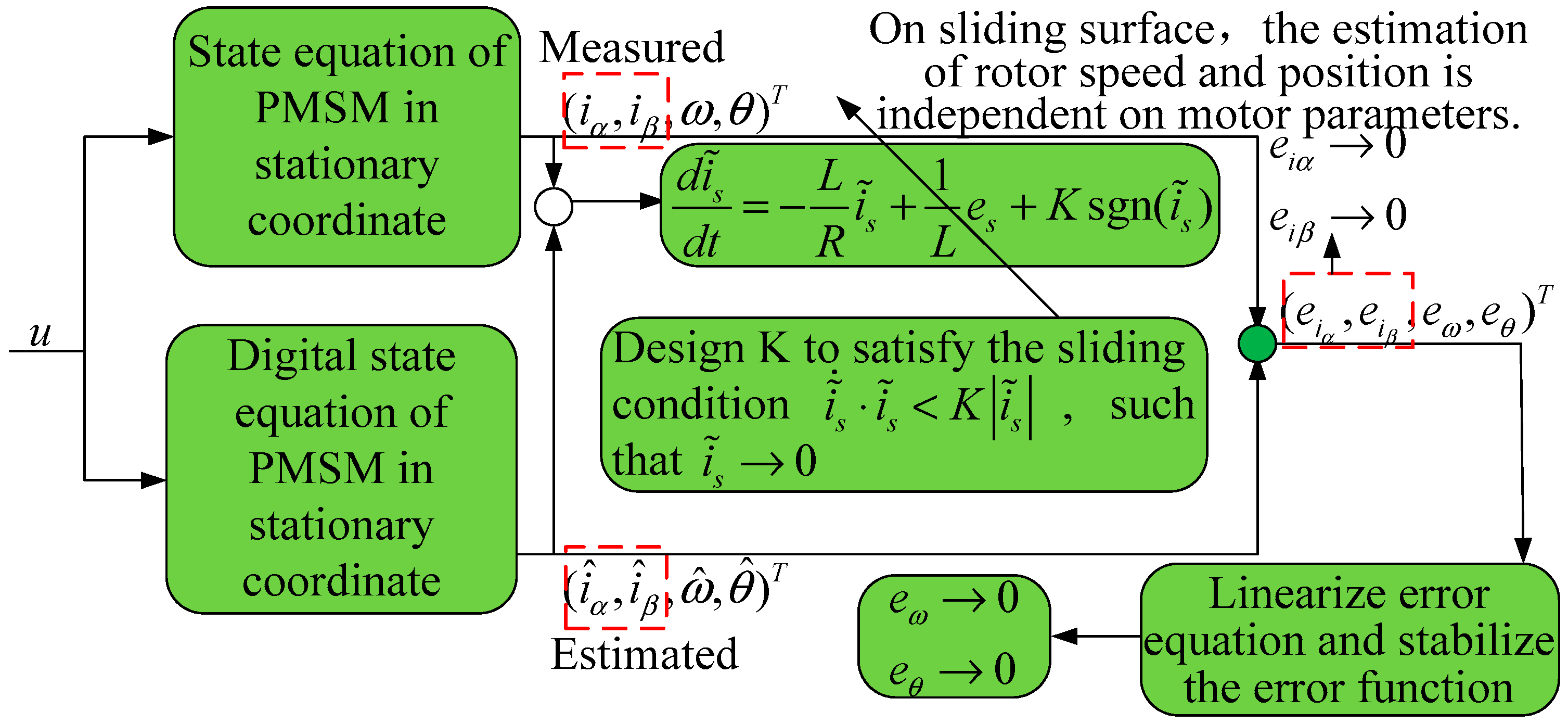
Figure 8.
Inverter platform.

Figure 9.
Experiment platform for start-up and operation with load.
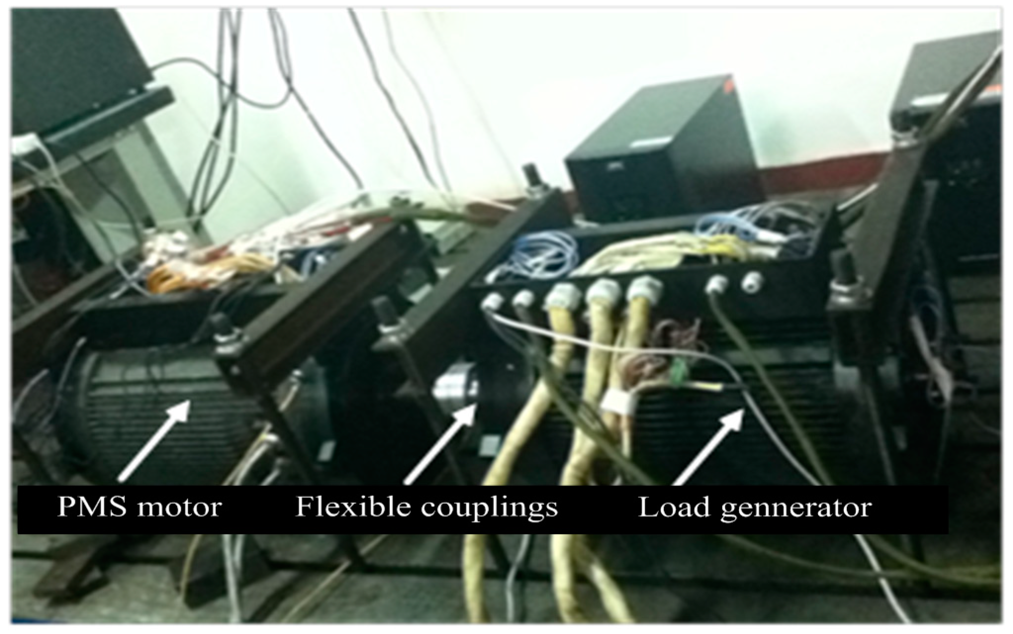
Figure 10.
Speed estimation and its error (a) operation estimation algorithm (b) start-up estimation algorithm.
Figure 10.
Speed estimation and its error (a) operation estimation algorithm (b) start-up estimation algorithm.
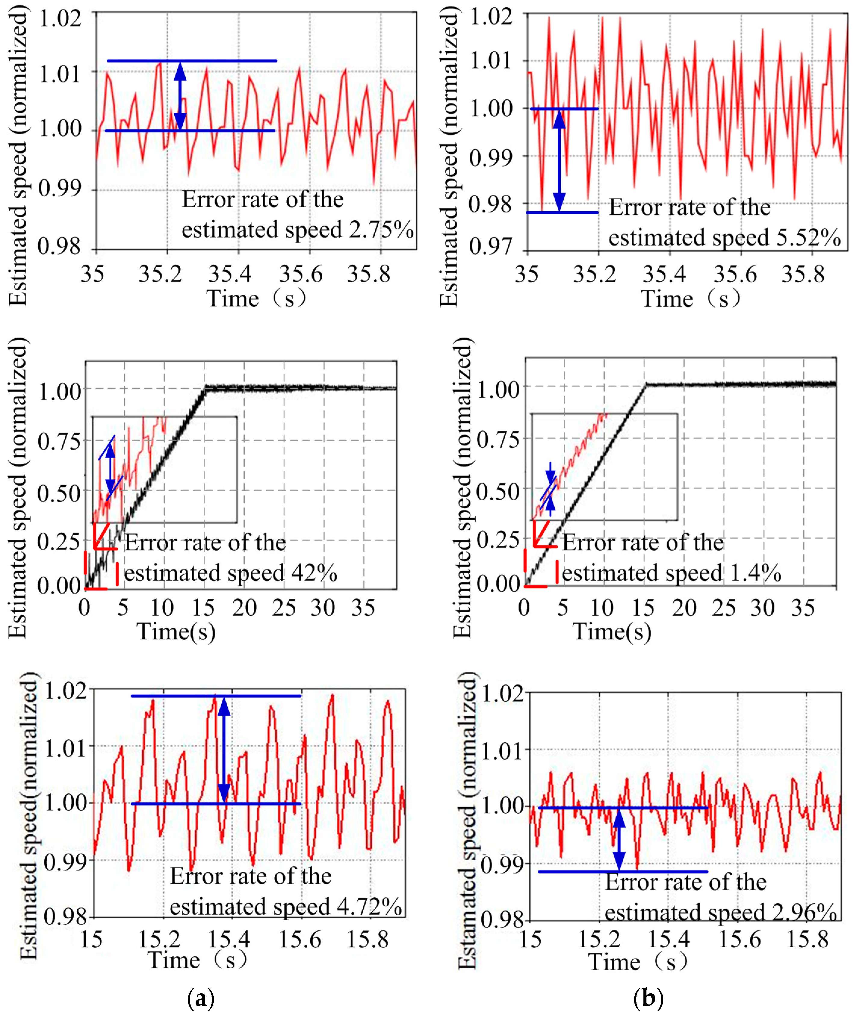
Figure 11.
Position estimation and its error (a) start-up estimation algorithm (b) operation estimation algorithm.
Figure 11.
Position estimation and its error (a) start-up estimation algorithm (b) operation estimation algorithm.

Figure 12.
Comparison for the output current of the observer and the measured current (a) Comparison for the output current of the start-up estimation algorithm and the measured current (b) and (c) Comparison for the output current of the operation estimation algorithm and the measured current.
Figure 12.
Comparison for the output current of the observer and the measured current (a) Comparison for the output current of the start-up estimation algorithm and the measured current (b) and (c) Comparison for the output current of the operation estimation algorithm and the measured current.

Figure 13.
Operation current of PMSM by general drive method.
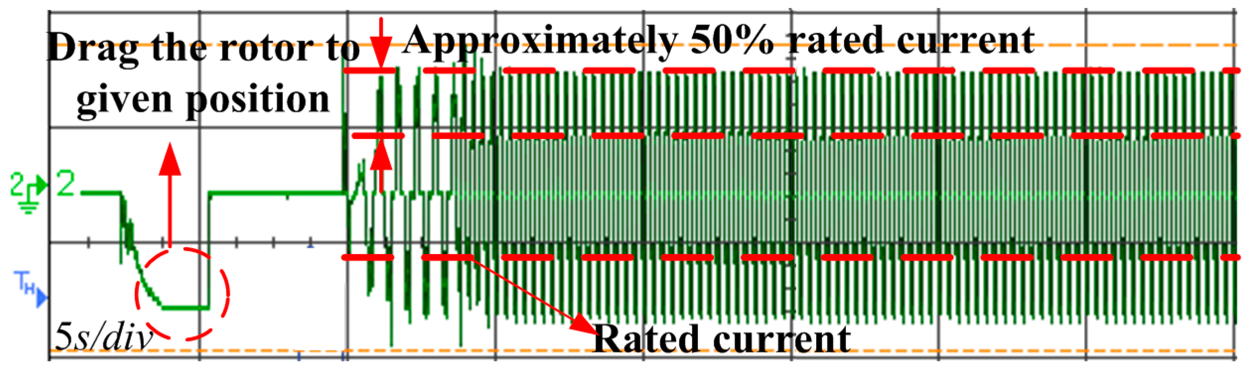
Figure 14.
Measured torque.

© 2018 by the authors. Licensee MDPI, Basel, Switzerland. This article is an open access article distributed under the terms and conditions of the Creative Commons Attribution (CC BY) license (http://creativecommons.org/licenses/by/4.0/).
Share and Cite
MDPI and ACS Style
Li, S.; Zhou, X. Sensorless Energy Conservation Control for Permanent Magnet Synchronous Motors Based on a Novel Hybrid Observer Applied in Coal Conveyer Systems. Energies 2018, 11, 2554. https://doi.org/10.3390/en11102554
AMA Style
Li S, Zhou X. Sensorless Energy Conservation Control for Permanent Magnet Synchronous Motors Based on a Novel Hybrid Observer Applied in Coal Conveyer Systems. Energies. 2018; 11(10):2554. https://doi.org/10.3390/en11102554
Chicago/Turabian StyleLi, Shun, and Xinxiu Zhou. 2018. "Sensorless Energy Conservation Control for Permanent Magnet Synchronous Motors Based on a Novel Hybrid Observer Applied in Coal Conveyer Systems" Energies 11, no. 10: 2554. https://doi.org/10.3390/en11102554
Note that from the first issue of 2016, this journal uses article numbers instead of page numbers. See further details here.