Numerical Study on Melting Heat Transfer in Dendritic Heat Exchangers

1
School of Energy Science and Engineering, Central South University, Changsha 410083, China
2
School of Civil Engineering and Architecture, East China Jiaotong University, Nanchang 330013, China
*
Author to whom correspondence should be addressed.
Energies 2018, 11(10), 2504; https://doi.org/10.3390/en11102504
Submission received: 22 August 2018
/
Revised: 16 September 2018
/
Accepted: 18 September 2018
/
Published: 20 September 2018
Abstract
:The dendritic fin was introduced to improve the solid-liquid phase change in heat exchangers. A theoretical model of melting phase change in dendritic heat exchangers was developed and numerically simulated. The solid-liquid phase interface, liquid phase rate and dynamic temperature change in dendritic heat exchanger during melting process are investigated and compared with radial-fin heat exchanger. The results indicate that the dendritic fin is able to enhance the solid-liquid phase change in heat exchanger for latent thermal storage. The presence of dendritic fin leads to the formation of multiple independent PCM zones, so the heat can be quickly diffused from one point to across the surface along the metal fins, thereby making the PCM far away from heat sources melt earlier and faster. In addition, the dendritic structure makes the PCM temperature distribution more uniform over the entire zone inside heat exchangers due to high-efficient heat flow distribution of dendritic fins. As a result, the time required for the complete melting of the PCM in dendritic heat exchanger is shorter than that of the radial-fin heat exchanger.
1. Introduction
The solid-liquid phase change process has a wide range of applications in industrial fields such as waste heat recovery [1,2,3], thermal energy storage [4,5], heat dissipation in electronic device [6,7,8,9] and building energy conservation [10,11], because of its significant advantages such as high energy density, minor volume change, and simple device structure. However, the thermal conductivity of most known phase change materials (PCM) is relatively low, which makes the heat transfer efficiency of the PCM heat storage process relatively low [5]. This property seriously restricts the application of thermal storage using solid-liquid phase change. Therefore, effectively improving the heat transfer efficiency in the solid-liquid phase change heat transfer process has become a key issue for the promotion and application of solid-liquid phase change to thermal storage in related fields. It has become a popular topic in the field of solid-liquid phase change heat transfer during past decades.
There has been a great deal of numerical and experimental works conducted to investigate the solid-liquid phase change heat transfer. As early as 1996, a numerical study concerning the thermal performance of water saturated in Al foam was completed by Tong et al. [12]. Feng et al. [13] compared the numerical simulation with an experimental study on the solidification behaviors of water saturated in open-cell metal foam to examine the heat transfer enhancement of solidification. Recently, Tian and Zhao [14] performed a numerical study on the melting heat transfer of PCM filled in metal foam. Their analysis implied that the enhancement of performance due to the higher thermal conductivity of metal foam would offset or exceed the natural convection loss as a consequence of the suppression of the flow resistance natural convection. The experimental study on the melting behaviors of paraffin saturated in open-celled metal foams performed by Li et al. [15] continued to provide data that is in good agreement with the numerical work done by themselves.
As a typical fractal geometry [16,17], dendritic structures are common in nature, such as the cardiac vascular system, the bifurcated structure of branches of trees, and the veins of leaves [17,18,19,20,21]. In addition, the blood circulation system in the human body with aorta (with an inner diameter of about 5 cm) bifurcating to the capillaries (with an inner diameter of only 8 to 10 μm) is also a typical dendritic structure [22]. These dendritic structures in nature are the results of the evolution of natural environment. The basic feature of the dendritic structure is bifurcation [17]. They have highly-efficient heat and mass transfer properties. At present, the dendritic structure has been widely used in optimizing the design of the channel structure in heat exchangers [23,24], chemical reactors [25], fuel cells [26,27] and microfluidic systems [28,29]. Moreover, the disc-shaped heat exchangers of dendritic structure, as a kind of point-to-area heat transfer structure, has been proved to be able to make even heat flow distribution and hence improve heat transfer performance as compared with traditional fin heat exchangers [30]. For this reason, the dendritic structure is introduced to improve heat transfer process of the solid-liquid phase change and hence enhance the thermal storage performance of heat exchangers.
Although heat transfer, fluid flow [30,31,32,33], and reaction transport [25,26] in dendritic structures have been well-studied, little attention has been paid to the enhancement of solid-liquid phase change heat transfer by the use of dendritic structures. In order to make an in-depth analysis of the heat transfer characteristics of the solid-liquid phase change and corresponding enhancement mechanism for the dendritic structure, dendritic structure fin is introduced to configure on the tube for increasing the heat transfer rate during the PCM melting process. In addition, a theoretical model of the PCM solid-liquid phase change heat transfer process within the dendritic heat exchanger was developed and numerically simulated. The melting characteristics and dynamic temperature evolution in the dendritic heat exchangers were studied and compared with the corresponding radial-fin structure, in an effort to reveal the heat transfer enhancement mechanism of the dendritic structure for PCM solid-liquid phase change.
2. Mathematical Model
2.1. Dendritic Heat Exchanger
In order to analyze the heat transfer improvement of the solid-liquid phase change using dendritic fins, a two-dimensional heat exchangers is investigated as an example. The geometrical structure of heat exchanger is shown in Figure 1. The dendritic fins are evenly distributed around the tube in an annular array with θ = 60°, where θ is the angle between each dendritic fin. The relationship between the length ln of the nth level bifurcation and the length ln+1 of the n + 1th level bifurcation can be defined by
where N is the bifurcation number at each level (i.e., N = 2), and D is fractal dimension of the bifurcation length for the dendritic fins (D = 2 is adopted in this study). The relationship of the each level for fin width is defined by
where dn is the fin width for the nth level bifurcation. In the formula, Δ is the fractal dimension of fin width (Δ = 3 is adopted in this study).
As shown in Figure 1, the geometry of the heat changer with dendritic structure presents an axisymmetric form. In order to simplify the calculation, only one-fourth of heat exchanger is numerically studied. The specific geometric structure is shown in Figure 2. For the heat exchanger, it is a tube configured with dendritic fins, the inner and outer radius of tube are Rin = 6 mm, Rout = 9 mm, and the outer diameter of heat exchange is Rc = 49 mm. It should be noted that the red area (see Figure 2) represents the heat source, and the black area is the metal fin with dendritic structure. In this paper, the metal fins are made of aluminum, and the space within the fins is filled with lauric acid (C12H24O2), which is a commonly used phase change material in engineering applications. The physical properties are of lauric acid and metal fin is shown in Table 1.
2.2. Control Equations and Boundary Conditions
In order to simplify the simulation, a 2D geometry is chosen to construct the geometry of the dendritic heat exchanger. The assumption of 2D geometry with no consideration of natural convection can be applied for the dendritic heat exchanger in the vertical state in the mathematical model. The available model capable of modeling PCM phase change includes the front tracking method, enthalpy method, effective heat capacity method, etc. Compared with other methods, the advantages of enthalpy-porosity method includes [34,35]: (1) The enthalpy-porosity method allows a fixed-grid solution of the coupled momentum and energy equations to be undertaken without resorting to variable transformations; (2) The enthalpy-porosity method introduces the liquid fraction of PCM to indicate the liquid-solid phase evaluation instead of tracking the location of phase interface directly; (3) The energy equation for the solid and liquid PCM can be unified in a formula. Therefore, the Enthalpy-Porosity model is used to solve the solid-liquid phase change problem in this study. It is believed in the model that the mushy zone with the coexistence of solid-liquid is compared to a porous medium, and the share of the liquid PCM in the mushy zone is equivalent to the porosity of porous medium. Based on this, the heat transfer of the solid phase, liquid phase and mushy phase is unified modelling. The enthalpy method is used to describe the melting process of PCM between dendritic fins. To simplify the calculation, the following assumptions are made in the numerical solution:
- (1)
- The physical properties (density, thermal conductivity, etc.) of the PCM are considered as constant;
- (2)
- Natural convection in the PCM liquid phase zone is ignored;
- (3)
- In the phase change process of PCM, there is solid state, liquid state, and solid-liquid coexistence state.
- (4)
- The specific heat capacity and thermal conductivity of the PCM in the mushy zone change linearly;
Based on the Enthalpy-porosity model, the non-steady heat transfer process of the PCM and dendritic fins during melting process was modeled, and the following energy equations use the enthalpy and temperature as variables [34,35]
where ρ, λ and h respectively represent the density, thermal conductivity and enthalpy, and τ represents time. It should be noted that the enthalpy h of the PCM in the solid phase zone is the sensible heat hT, while the enthalpy h in the liquid phase zone and the mushy zone of the phase change material is the sum of sensible heat hT and the latent heat Δh. The expression is
where cp is the specific heat capacity of PCM, and Tref is the reference temperature.
The Enthalpy-Porosity model does not directly track the movement of the solid-liquid interface during the melting phase change process of the PCM. Instead, the enthalpy-porosity equation replaces the phase interface in the solid-liquid phase transition process. The mushy zone is regarded as the porous medium filled with the liquid phase PCM, and the liquid phase ratio β is introduced to characterize the fraction of the liquid phase occupied by the phase change material, and β is generally defined by
In the formula, Ts and Tl are the solidus temperature and liquidus temperature of PCM, respectively. The enthalpy-porosity method introduces a quantity called the liquid fraction to describe the fraction of the cell volume that is in liquid form. The liquid fraction is calculated at each iteration by the use of enthalpy balance equation. When the material is completely solidified in a cell, the porosity is zero. The porosity is 1 when the material is completely melted in a cell.
After introducing the concept of liquid volume fraction β, the enthalpy h of PCM in energy equation can be unified to
where Lp represents the latent heat of PCM. In addition, according to the Assumption (4), the specific heat capacity and thermal conductivity of the PCM in the mushy zone are linearly changed.
The internal pipeline of heat exchangers is such that the heat fluid serves as a heat source. That is, the boundary of the inner wall surface of the pipeline can be set as a constant temperature boundary. Assume that a heat insulating layer is arranged outside the heat exchangers. Therefore, it can be assumed that the outer wall surface of the heat exchangers is an adiabatic boundary. Due to the symmetrical structure of the heat exchanger, the other two boundaries (see Figure 2) are also adiabatic. The dendritic fins are thermally coupled to the PCM surface at the conjugant boundary with the same temperature and continuous heat flux.
At the initial moment, the dendritic fins and the PCM between the fins are in thermal equilibrium. Therefore, the temperature of the whole zone of heat exchanger is the same. Assume that the pipe wall temperature Tw and the initial temperature T0 are constant, and the initial temperature difference ΔT is defined as ΔT = Tw − T0. In the numerical, the heating boundary temperature Tw of the pipe is set at 350 K, and the initial temperature T0 at 300 K, so ΔT = 50 K.
2.3. Numerical Solutions
In order to study the enhancement of the dendritic structure on the PCM solid-liquid phase change, it is necessary to solve the control equations of the two-dimensional non-steady heat transfer model with PCM phase change, with an emphasis on heat release characteristics of PCM between dendritic fins during melting.
Due to the complex structure of the dendritic fins and the complex coupling boundary in contact with PCMs, the entire dendritic heat exchangers are meshed structurally, and part of the acquired structure grid is shown in Figure 3a. The finite volume method is used to solve the energy equation. In each control unit volume, a discrete equation used the enthalpy as a variable. A fully implicit control volume finite difference scheme is applied in the discrete equation. In the process of numerical solution, at each time step, the known enthalpy hτ(k) and the liquidus ratio βτ(k) at the previous moment in each control unit volume are substituted into the discrete energy equation to solve the next moment enthalpy value hτ(k+1) and liquid phase rate βτ(k+1). In this process, liquid phase rate of PCM, β, can be obtained by enthalpy conservation. At each time step, the enthalpy and liquid ratios of the PCM at the each control volume for the computational domain can be calculated by the numerical solution of the resulting system of algebraic equations using the Gauss-Seidel iterative technique. As the time proceeds, the time-dependence of enthalpy and liquid fraction can be obtained for the heat exchanger, i.e., the heat transfer characteristics of the dendritic heat exchanger during the PCM melting process are obtained.
It should be noted that during each iteration, if the absolute values of the enthalpy hτ(k) at a moment and the enthalpy hτ(k+1) at the next moment are within the calculated residual 10−9, it can be considered that this time step iteration has converged. Conversely, it is necessary to sub-relax the enthalpy values obtained from the discrete equations of the energy equations. The relaxation factor is set as 0.9. The corrected enthalpy values are then entered in the next iteration. In order to understand the melting process at different zones of the PCM between the dendritic fins, several corresponding temperature monitoring points are set to determine the trend of temperature changes at important locations in the PCM area. In addition, in order to eliminate the correlation between the numerical calculation results and the number of structured grids, the solutions of numerical equations are independent from the grid, and grid independence is also tested to confirm the optimal number of cells for numerical solution. In this paper, the melting heat transfer in heat exchanger is simulated using Ansys Fluent.
Figure 3b depicts the grid number on the average temperature of PCM in the dendritic heat exchanger during melting process with different mesh sizes. In the present simulations, the grid number varies from 21,394 to 273,673. As shown in the figure, with the increase of grid number, the difference of PCM average temperature during melting process can be considered negligible when the grid number Ng > 127,291. Considering the time cost, the grid number is chosen as Ng = 127,291 in the simulation.
3. Results and Discussion
In order to verify the enhancement of the dendritic structure in the solid-liquid phase change heat transfer process, the melting processes of the PCM in the heat exchangers with radial-fin and dendritic structures were comparatively studied. Considering the importance of fin volume in the application latent heat storage thermal energy storage, the evaluation of thermal performance for the heat exchangers with a dendritic structure and a radial plain fin structure is based on the same fin volume (i.e., also same mass of fin). For the two-dimensional cross section, the fin area occupying the whole cross-sectional area of the heat exchanger is identical. In addition, these two heat exchangers exhibit six identical fins around the axis of the pipeline in an annular array. The specific dimensions are as shown in Table 2. In the simulation, the heat exchangers are imposed by the same heat boundary condition with a constant temperature. The manufacturing methods, including the die casting and line cutting, can be applied to produce the dendritic fin. For large-scale applications with die casting, the cost of dendritic fin is possibly the same as those with flat plain fins or wavy fins.
3.1. Melt Phase Change Characteristics
When pure PCM undergoes a solid-liquid phase change, it is necessary to improve the heat transfer performance of solid-liquid phase change due to the low thermal conductivity of PCM. To this end, the fins are usually used to strengthen the melting rate of the PCM in heat exchangers. To analyze the solid-liquid phase change heat transfer of the PCM enhanced by dendritic structure, Figure 4 compares the evolution of the solid-liquid interface of the PCM between the dendritic fins and radial fins during melting process under the same initial temperature difference. As can be seen from the figure, during the melting process, the solid-liquid interface of the PCM between radial fins moves very slowly and almost straight along the vertical direction of the fins towards the outer area. However, the PCM between dendritic fins form multiple independent PCM zones of different sizes due to the division of the fins, so that the heat can be quickly diffused from one point to across the surface along the metal fins, thereby making the PCM in the far area of the heat sources and metal fins melt earlier. Moreover, compared with the radial-fin structure, some PCM between dendritic fins and farther away from the heat sources can also melt at a faster rate.
To further analyze the influence of the dendritic structure on solid-liquid phase change, Figure 5 shows liquid phase ratios of PCM as a function of time during the melting process under the same initial temperature difference. It can be clearly seen from the figure that for the same volume of PCM, the time required for the PCM to complete the melting process in dendritic heat exchanger is less than those in the radial-fin heat exchanger. This implies that under the case of heating the boundary with constant temperature, the heat fluxes of dendritic heat exchanger is larger than the corresponding heat exchanger with radial plain fins. This is mainly due to the fact that the specific surface area of the dendritic fins is larger than that of the radial-fin structure, which increases the contact area with the PCM, thereby enhancing the heat transfer rate during the melting process. It is interesting to observe from Figure 5 that at the initial moment of melting, the melting rate of the PCM between radial fins is slightly faster than that of the PCM between dendritic fins. This is attributed to the thicker radial fins as compared with the dendritic structure, so the fin efficiency of main fin with radial structure is relatively high, and the nearby PCM therefore have a faster melting rate at the initial stage. In addition, it should be noted that the growth tendencies of the liquid phase rate for the PCM between the fins tend to level off with time. Due to the further development of the PCM melting process, the temperature difference between the fin and PCM gradually decreases, correspondingly resulting in an increase in the thermal resistance in heat transfer. Therefore, the melting rate of the PCM between metal fins will be reduced accordingly.
3.2. Dynamic Temperature Changes
Dendritic fins have an important role in the PCM melting process. To understand this, Figure 6 compares the temperature dynamic change of the PCM in the heat exchanger between dendritic structure and radial-fin structure. As seen from the figure, in the area near the heat source, the dynamic temperature changes of the PCM between the dendritic fins and radial fins are almost the same. However, as the distance from the heat source increases, the dynamic temperature change of the PCM between dendritic fins is higher than that between the radial fins. The explanation for this phenomenon is that the heat transfer rate in the PCM between dendritic fins is higher during the melting process, thereby effectively improving the heat transfer of the entire PCM area in heat exchangers. In addition, during the melting process of PCM, the dynamic temperature difference of the PCM at different positions in dendritic heat exchanger is distinctly smaller than that in the radial-fin heat exchanger. This phenomenon indicates that the dendritic fins not only improve the melting rate of the PCM, but also effectively optimize the even temperature distribution across the entire PCM zone.
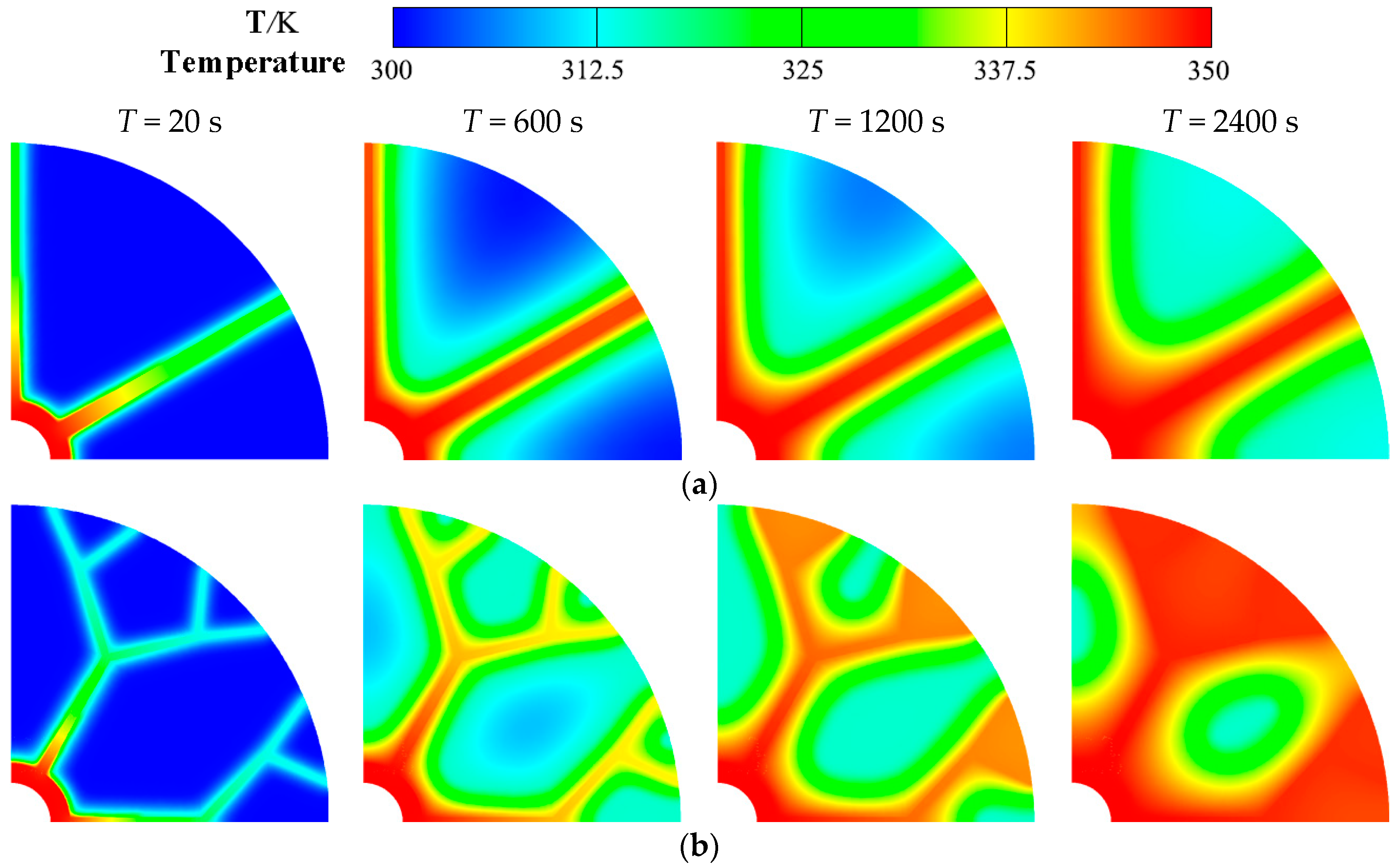
Figure 7 compares the temperature distribution during PCM melting between the dendritic and the radial-fin heat exchanger. This temperature distribution helps to visualize the heat transfer characteristics of PCM between metal fins during melting. It can be clearly seen from the figure that during the PCM melting process, the temperature difference between the different zones inside heat exchangers of radial-fin structure is relatively obvious, where the high temperature zone is mainly concentrated near the fins and the temperature is relatively low farther from the fins. However, due to the highly-efficient heat flow distribution of dendritic fins, heat can quickly spread out along the fins from point to area, making the temperature spread more uniform throughout the PCM area.
4. Conclusions
In this paper, a two-dimensional model of unsteady heat transfer with PCM melting is developed and numerically simulated. The solid-liquid phase interface, liquid phase rates and dynamic temperature change in dendritic heat exchanger during the melting process is presented and compared with plain radial fin. It is indicated that the dendritic structure enhances the solid-liquid phase change in heat exchangers for latent thermal storage. The main conclusions can be drawn as follows:
- (1)
- The solid-liquid phase interface in the heat exchanger with plain radial fin moves very slowly and almost straight along the vertical direction of the fins towards the outer area. However, the presence of dendritic fin leads to the formation of multiple independent PCM zones, and make the PCM far away from heat sources melt earlier and faster.
- (2)
- The whole heat transfer performance in dendritic heat exchanger is superior owing to additional fin surface-area and better fin configuration. The time required for the complete melting of the PCM in dendritic heat exchanger is shorter than that of the radial-fin heat exchanger.
- (3)
- The temperature difference in the whole region of PCM within heat exchangers with radial plain fin is clear, however, the dendritic structure makes the PCM temperature distribution over the entire zone more uniform inside heat exchangers due to the highly-efficient heat flow distribution of dendritic fins.
Author Contributions
Conceptualization, X.L. and S.L.; Methodology, X.L.; Writing-Original Draft Preparation, X.L.; Writing-Review & Editing, X.L., S.L.; All authors read and approved the final manuscript.
Funding
This work was funded by the National Natural Science Foundation of China under Grant No. 21466012.
Conflicts of Interest
The authors declare no conflict of interest.
Nomenclature
| cp | specific heat capacity |
| D | fractal dimension of bifurcation length |
| d | fin width |
| hT | sensible heat |
| h | enthalpy |
| Lp | latent heat |
| l | fin length |
| N | bifurcation number |
| Ng | grid number |
| Rc | outer diameter of heat exchange |
| Rin | inner radius of tube |
| Rout | outer radius of tube |
| T0 | initial temperature |
| Tl | liquidus temperature |
| Tp | temperature of solid-liquid interface |
| Tref | reference temperature |
| Ts | solidus temperature |
| Tw | wall temperature |
| Greek Symbols | |
| β | liquid phase ratio |
| Δ | fractal dimension of fin width |
| θ | angle between each fin |
| λ | thermal conductivity |
| ρ | density |
| τ | time |
References
- Shon, J.; Kim, H.; Lee, K. Improved heat storage rate for an automobile coolant waste heat recovery system using phase-change material in a fin–tube heat exchanger. Appl. Energy 2014, 113, 680–689. [Google Scholar] [CrossRef]
- Merlin, K.; Soto, J.; Delaunay, D.; Traonvouez, L. Industrial waste heat recovery using an enhanced conductivity latent heat thermal energy storage. Appl. Energy 2016, 183, 491–503. [Google Scholar] [CrossRef]
- Dal Magro, F.; Jimenez-Arreola, M.; Romagnoli, A. Improving energy recovery efficiency by retrofitting a PCM-based technology to an ORC system operating under thermal power fluctuations. Appl. Energy 2017, 208, 972–985. [Google Scholar] [CrossRef]
- Deng, Z.L.; Liu, X.D.; Zhang, C.B.; Huang, Y.P.; Chen, Y.P. Melting behaviors of PCM in porous metal foam characterized by fractal geometry. Int. J. Heat Mass Transf. 2017, 113, 1031–1042. [Google Scholar] [CrossRef]
- Sharma, A.; Tyagi, V.V.; Chen, C.R.; Buddhi, D. Review on thermal energy storage with phase change materials and applications. Renew. Sustain. Energy Rev. 2009, 13, 318–345. [Google Scholar] [CrossRef]
- Liu, X.D.; Chen, Y.P.; Shi, M.H. Dynamic performance analysis on start-up of closed-loop pulsating heat pipes (CLPHPs). Int. J. Therm. Sci. 2013, 65, 224–233. [Google Scholar] [CrossRef]
- Behi, H.; Ghanbarpour, M.; Behi, M. Investigation of PCM-assisted heat pipe for electronic cooling. Appl. Therm. Eng. 2017, 127, 1132–1142. [Google Scholar] [CrossRef]
- Wu, J.F.; Shi, M.H.; Chen, Y.P.; Li, X. Visualization study of steam condensation in wide rectangular silicon microchannels. Int. J. Therm. Sci. 2010, 49, 922–930. [Google Scholar] [CrossRef]
- Bondareva, N.S.; Sheremet, M.A. Conjugate heat transfer in the PCM-based heat storage system with finned copper profile: Application in electronics cooling. Int. J. Heat Mass Transf. 2018, 124, 1275–1284. [Google Scholar] [CrossRef]
- Saffari, M.; de Gracia, A.; Fernández, C.; Cabeza, L.F. Simulation-based optimization of PCM melting temperature to improve the energy performance in buildings. Appl. Energy 2017, 202, 420–434. [Google Scholar] [CrossRef]
- Chen, Z.Q.; Gao, D.Y.; Shi, J. Experimental and numerical study on melting of phase change materials in metal foams at pore scale. Int. J. Heat Mass Transf. 2014, 72, 646–655. [Google Scholar] [CrossRef]
- Tong, X.L.; Khan, J.A.; RuhulAmin, M. Enhancement of heat transfer by inserting a metal matrix into a phase change material. Numer. Heat Transf. Part A Appl. 1996, 30, 125–141. [Google Scholar] [CrossRef]
- Feng, S.S.; Zhang, Y.; Shi, M.; Wen, T.; Lu, T.J. Unidirectional freezing of phase change materials saturated in open-cell metal foams. Appl. Therm. Eng. 2015, 88, 315–321. [Google Scholar] [CrossRef]
- Tian, Y.; Zhao, C.Y. A numerical investigation of heat transfer in phase change materials (PCMs) embedded in porous metals. Energy 2011, 36, 5539–5546. [Google Scholar] [CrossRef] [Green Version]
- Li, W.Q.; Qu, Z.G.; He, Y.L.; Tao, W.Q. Experimental and numerical studies on melting phase change heat transfer in open-cell metallic foams filled with paraffin. Appl. Therm. Eng. 2012, 37, 1–9. [Google Scholar] [CrossRef]
- Zhang, C.B.; Chen, Y.P.; Deng, Z.L.; Shi, M.H. Role of rough surface topography on gas slip flow in microchannels. Phys. Rev. E 2012, 86, 016319. [Google Scholar] [CrossRef] [PubMed]
- Bejan, A.; Errera, M.R. Deterministic tree networks for fluid flow: Geometry for minimal flow resistance between a volume and one point. Fractals 1997, 5, 685–695. [Google Scholar] [CrossRef]
- Errera, M.; Bejan, A. Deterministic tree networks for river drainage basins. Fractals 1998, 6, 245–261. [Google Scholar] [CrossRef]
- Zhang, C.B.; Deng, Z.L.; Chen, Y.P. Temperature jump at rough gas–solid interface in Couette flow with a rough surface described by Cantor fractal. Int. J. Heat Mass Transf. 2014, 70, 322–329. [Google Scholar] [CrossRef]
- Pelletier, J.D.; Turcotte, D.L. Shapes of river networks and leaves: Are they statistically similar? Philos. Trans. R. Soc. B-Biol. Sci. 2000, 355, 307–311. [Google Scholar] [CrossRef] [PubMed]
- Neagu, M.; Bejan, A. Constructal-theory tree networks of “constant” thermal resistance. J. Appl. Phys. 1999, 86, 1136–1144. [Google Scholar] [CrossRef]
- Gabryś, E.; Rybaczuk, M.; Kędzia, A. Blood flow simulation through fractal models of circulatory system. Chaos Solitons Fractals 2006, 27, 1–7. [Google Scholar] [CrossRef]
- Zhang, C.B.; Chen, Y.P.; Wu, R.; Shi, M.H. Flow boiling in constructal tree-shaped minichannel network. Int. J. Heat Mass Transf. 2011, 54, 202–209. [Google Scholar] [CrossRef]
- Zimparov, V.; Da Silva, A.; Bejan, A. Constructal tree-shaped parallel flow heat exchangers. Int. J. Heat Mass Transf. 2006, 49, 4558–4566. [Google Scholar] [CrossRef]
- Chen, Y.P.; Zhang, C.B.; Wu, R.; Shi, M.H. Methanol steam reforming in microreactor with constructal tree-shaped network. J. Power Source 2011, 196, 6366–6373. [Google Scholar] [CrossRef]
- Senn, S.; Poulikakos, D. Laminar mixing, heat transfer and pressure drop in tree-like microchannel nets and their application for thermal management in polymer electrolyte fuel cells. J. Power Source 2004, 130, 178–191. [Google Scholar] [CrossRef]
- Senn, S.; Poulikakos, D. Tree network channels as fluid distributors constructing double-staircase polymer electrolyte fuel cells. J. Appl. Phys. 2004, 96, 842–852. [Google Scholar] [CrossRef]
- Chen, Y.P.; Deng, Z.L. Hydrodynamics of a droplet passing through a microfluidic T-junction. J. Fluid Mech. 2017, 819, 401–434. [Google Scholar] [CrossRef]
- Chen, Y.P.; Liu, X.D.; Shi, M.H. Hydrodynamics of double emulsion droplet in shear flow. Appl. Phys. Lett. 2013, 102, 051609. [Google Scholar] [CrossRef]
- Wang, X.-Q.; Mujumdar, A.S.; Yap, C. Thermal characteristics of tree-shaped microchannel nets for cooling of a rectangular heat sink. Int. J. Therm. Sci. 2006, 45, 1103–1112. [Google Scholar] [CrossRef]
- Chen, Y.P.; Zhang, C.B.; Shi, M.H.; Yang, Y.C. Thermal and hydrodynamic characteristics of constructal tree-shaped minichannel heat sink. AIChE J. 2010, 56, 2018–2029. [Google Scholar] [CrossRef]
- Wechsatol, W.; Lorente, S.; Bejan, A. Tree-shaped flow structures with local junction losses. Int. J. Heat Mass Transf. 2006, 49, 2957–2964. [Google Scholar] [CrossRef]
- Chen, Y.P.; Gao, W.; Zhang, C.B.; Zhao, Y.J. Three-dimensional splitting microfluidics. Lab Chip 2016, 16, 1332–1339. [Google Scholar] [CrossRef] [PubMed]
- Voller, V.R.; Prakash, C. A fixed grid numerical modelling methodology for convection-diffusion mushy region phase-change problems. Int. J. Heat Mass Transf. 1987, 30, 1709–1719. [Google Scholar] [CrossRef]
- Brent, A.; Voller, V.; Reid, K. Enthalpy-porosity technique for modeling convection-diffusion phase change: application to the melting of a pure metal. Numer. Heat Transf. Part A Appl. 1988, 13, 297–318. [Google Scholar]
Figure 1.
Schematic of dendritic heat exchangers.
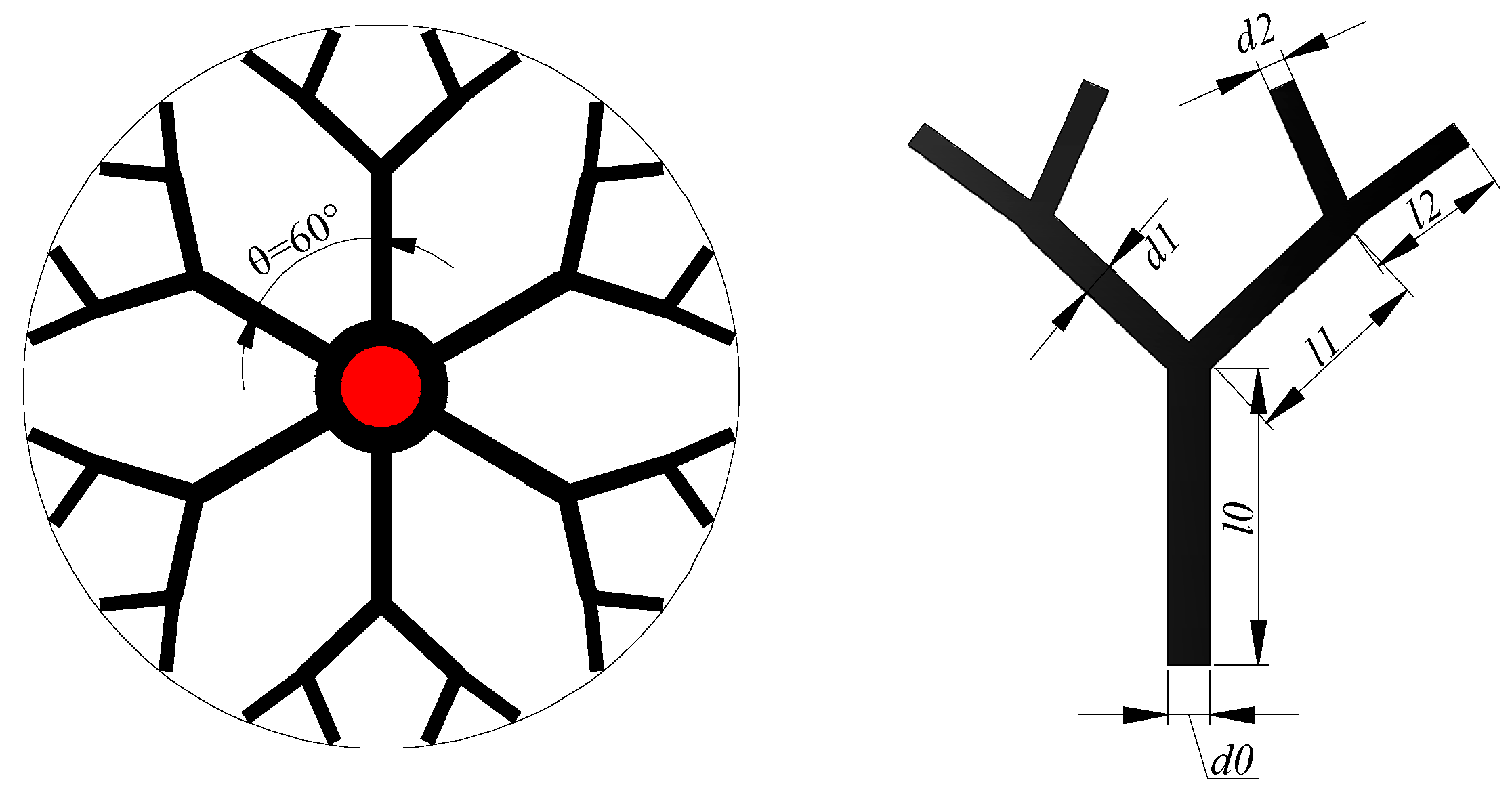
Figure 2.
Computational domain of a dendritic heat exchanger.

Figure 3.
Local mesh and grid independence test for numerical simulation: (a) Local mesh; (b) Grid independence test.
Figure 3.
Local mesh and grid independence test for numerical simulation: (a) Local mesh; (b) Grid independence test.
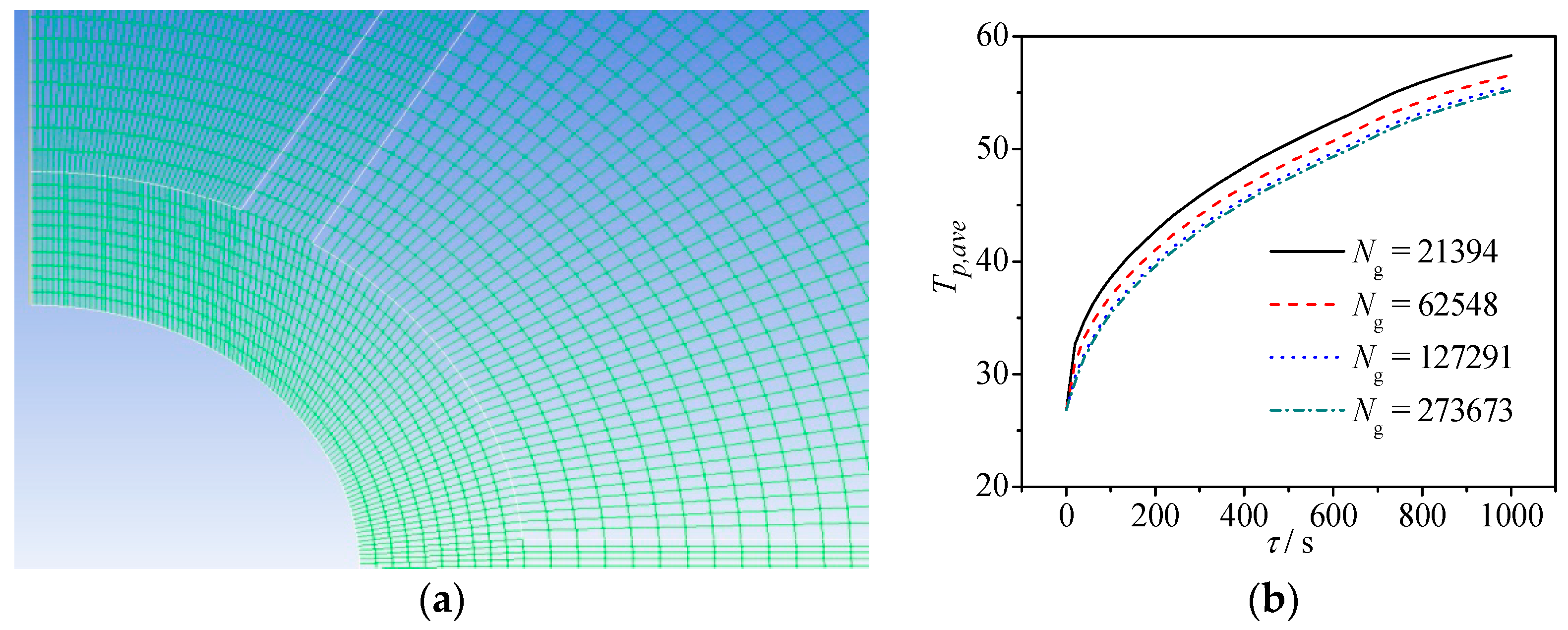
Figure 4.
Evolution of solid-liquid phase interface during PCM melting: (a) Radial-fin structure; (b) Dendritic structure.
Figure 4.
Evolution of solid-liquid phase interface during PCM melting: (a) Radial-fin structure; (b) Dendritic structure.
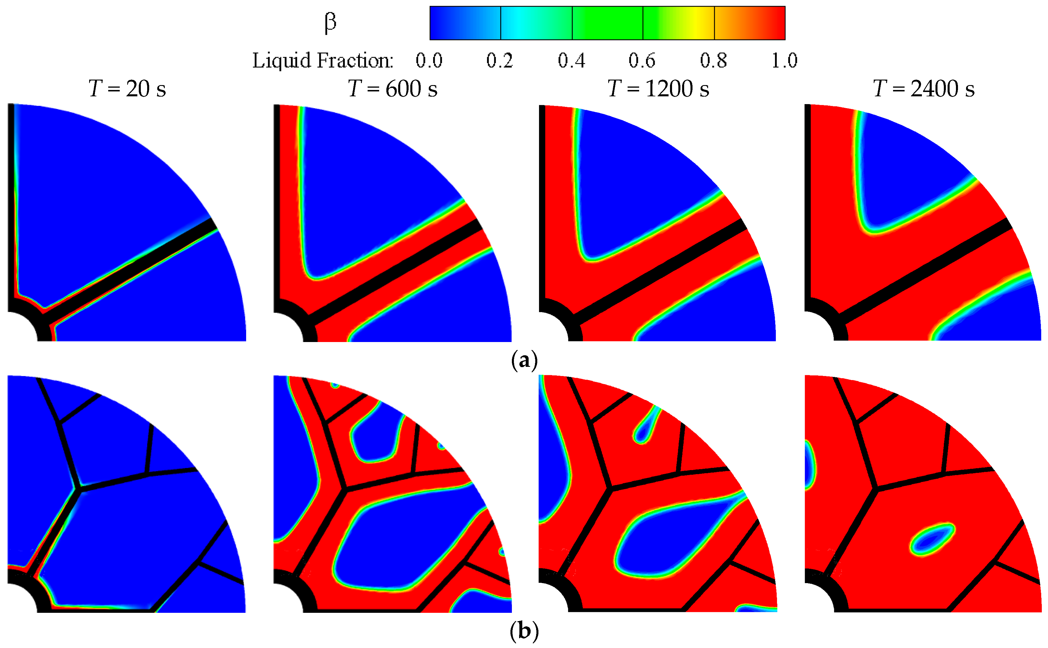
Figure 5.
Liquid phase rates of PCMs in heat exchangers during melting.
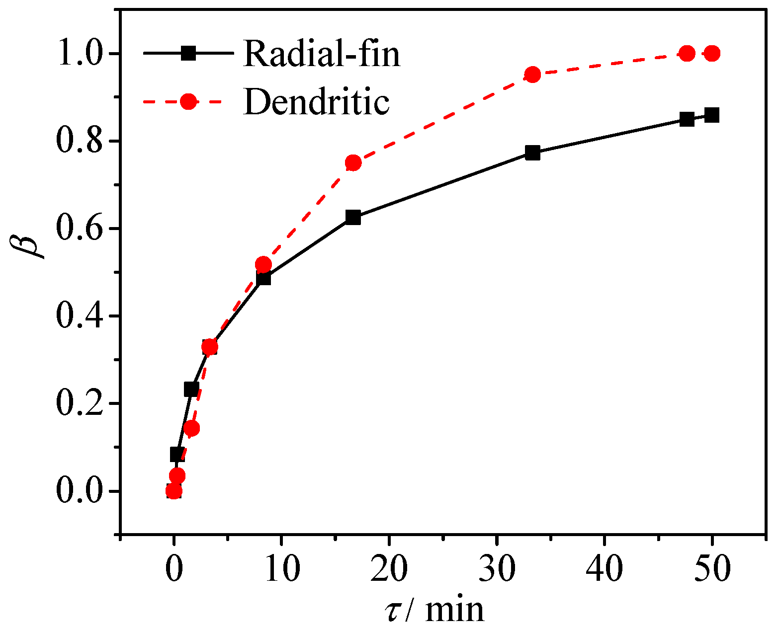
Figure 6.
Temperature evolution of PCM in radial-fin and dendritic heat exchangers: (a) Dynamic temperature variations; (b) Positions of temperature.
Figure 6.
Temperature evolution of PCM in radial-fin and dendritic heat exchangers: (a) Dynamic temperature variations; (b) Positions of temperature.
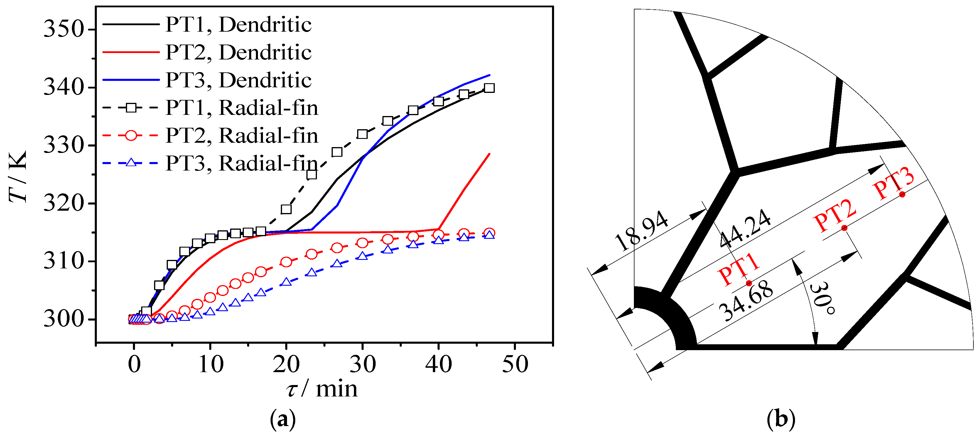
Figure 7.
Dynamic temperature changes in radial-fin and dendritic heat exchangers: (a) Radial-fin structure; (b) Dendritic structure.
Figure 7.
Dynamic temperature changes in radial-fin and dendritic heat exchangers: (a) Radial-fin structure; (b) Dendritic structure.

Table 1.
Physical properties of phase change materials and metal fin.
| Material | Density P (Kg/M3) | Specific Heat Capacity C (J/Kg·K) | Thermal Conductivity Λ (W/M·K) | Latent Heat of Phase Change Lp (J/Kg) | Phase Change Temperature Tp (K) |
|---|---|---|---|---|---|
| Lauric acid (C12H24O2) | 1000 | 2150 | 0.15 | 178,000 | 315 (Solid Phase) 317 (Liquid phase) |
| Aluminum | 2719 | 871 | 202.4 | / | / |
Table 2.
Dimensions of single radial-fin and dendritic fins.
| Fin Shape | Length, l (mm) | Width, d (mm) |
|---|---|---|
| Radial-fin | 39.5 | 4.8 |
| Dendritic | l0 = 9.3 | d0 = 2.47 |
| l1 = 13.15 | d1 = 1.96 | |
| l2 = 18.6 | d2 = 1.56 |
© 2018 by the authors. Licensee MDPI, Basel, Switzerland. This article is an open access article distributed under the terms and conditions of the Creative Commons Attribution (CC BY) license (http://creativecommons.org/licenses/by/4.0/).
Share and Cite
MDPI and ACS Style
Luo, X.; Liao, S. Numerical Study on Melting Heat Transfer in Dendritic Heat Exchangers. Energies 2018, 11, 2504. https://doi.org/10.3390/en11102504
AMA Style
Luo X, Liao S. Numerical Study on Melting Heat Transfer in Dendritic Heat Exchangers. Energies. 2018; 11(10):2504. https://doi.org/10.3390/en11102504
Chicago/Turabian StyleLuo, Xinmei, and Shengming Liao. 2018. "Numerical Study on Melting Heat Transfer in Dendritic Heat Exchangers" Energies 11, no. 10: 2504. https://doi.org/10.3390/en11102504
Note that from the first issue of 2016, this journal uses article numbers instead of page numbers. See further details here.