Article

Analytical Investigation of the Heat-Transfer Limits of a Novel Solar Loop-Heat Pipe Employing a Mini-Channel Evaporator

1
School of Engineering, University of Hull, Hull HU6 7RX, UK
2
Department of Thermal Science and Energy Engineering, University of Science and Technology of China, Hefei 230026, China
*
Authors to whom correspondence should be addressed.
Energies 2018, 11(1), 148; https://doi.org/10.3390/en11010148
Submission received: 21 November 2017 / Revised: 2 January 2018 / Accepted: 4 January 2018 / Published: 8 January 2018
(This article belongs to the Special Issue Solar Technologies for Buildings)

Abstract

:
This paper presents an analytical investigation of heat-transfer limits of a novel solar loop-heat pipe developed for space heating and domestic hot water use. In the loop-heat pipe, the condensate liquid returns to the evaporator via small specially designed holes, using a mini-channel evaporator. The study considered the commonly known heat-transfer limits of loop-heat pipes, namely, the viscous, sonic, entrainment, boiling and heat-transfer limits due to the two-phase pressure drop in the loop. The analysis considered the main factors that affect the limits in the mini-channel evaporator: the operating temperature, mini-channel aspect ratio, evaporator length, evaporator inclination angle, evaporator-to-condenser height difference and the dimension of the holes. It was found that the entrainment is the main governing limit of the system operation. With the specified loop design and operational conditions, the solar loop-heat pipe can achieve a heat-transport capacity of 725 W. The analytical model presented in this study can be used to optimise the heat-transfer capacity of the novel solar loop-heat pipe.

1. Introduction

Loop-heat pipes (LHPs) are two-phase heat-transfer (evaporation/condensation) devices that are able to transfer large amounts of heat over long distances due to a capillary or gravitational structure [1,2]. The major advantages of LHPs compared to heat pipes (HPs) are an ability to operate against gravity and a higher maximum heat-transport capacity [1]. The maximum heat-transport capacity for an LHP system is governed by different limits, including the viscous, sonic, entrainment, boiling and capillary limits [3]. The minimum value of these limits represents the maximum heat-transport capacity of the LHP system, which is the maximum amount of heat the LHP system could transfer. This maximum heat-transfer capacity represents the most significant performance characteristic of an LHP [3]. Due to the above advantages, LHPs are ideally suitable for use in solar collection systems for hot water and space heating use, which allow heat to be collected by an evaporator outside a building, and transfer it to water flowing across the heat exchanger. Therefore, in recent years, some numerical and experimental studies have been performed to study the heat-transfer limit and thermal performance of conventional LHPs applied to solar collectors [4,5,6,7]. Existing solar LHPs are not technically mature; there are still opportunities to enhance their maximum heat-transport capacity and thermal performance [3]. An efficient way to enhance the thermal performance of solar LHPs could be the use of mini-channel heat pipes (MCHPs) in the evaporator. MCHPs are characterised by a hydraulic diameter range of 0.5 to 5 mm [8]. To our knowledge, this way to improve the thermal performance of solar LHPs has not yet been investigated and reported. However, the use of mini-channels in solar heat pipe collectors has been numerically and experimentally investigated because of their higher thermal performance compared to conventional HPs [9,10,11,12]. In order to improve the performance of solar LHP systems, in this study a novel solar LHP system employing a mini-channel heat pipe evaporator is proposed. However, before a thermal performance characterisation of the novel LHP system is conducted, there is a need to assess its maximum heat-transport capacity. Few studies have been performed upon the heat-transfer limits of solar LHPs for the determination of their heat-transfer governing limit and maximum heat-transport capacity [13,14]. The available studies concern solar LHPs that employ conventional wicked evaporator channels with a hydraulic diameter greater than 4 mm. Wang and Zhao [13] showed that, for their solar LHP system (with heat pipe diameter ranges from 4 to 10 mm), the capillary limit was the governing heat-transfer limit for heat pipe diameters above 5.6 mm, while the entrainment limit was the governing limit for diameters below 5.6 mm. Zhang et al. [14] showed that the capillary limit was the main governing limit of their LHP system (with heat pipe diameter ranges from 14 to 22 mm).
In this paper, an analytical investigation of the heat-transfer limits for a novel solar LHP, employing a wickless mini-channel heat pipe evaporator, is realised. Firstly, the novel solar LHP operation and design characteristics are presented. Particularly, a special design for the condensate return path to the mini-channel evaporator is proposed. Secondly, the paper presents a computer model developed to estimate the heat-transfer limits (viscous, sonic, entrainment, boiling and pressure-drop limits) of the LHP system and then its heat-transport capacity. Finally, the paper presents a parametric analysis of the main factors of the mini-channel heat pipe evaporator that can affect the heat-transfer capacity system.

2. Methods

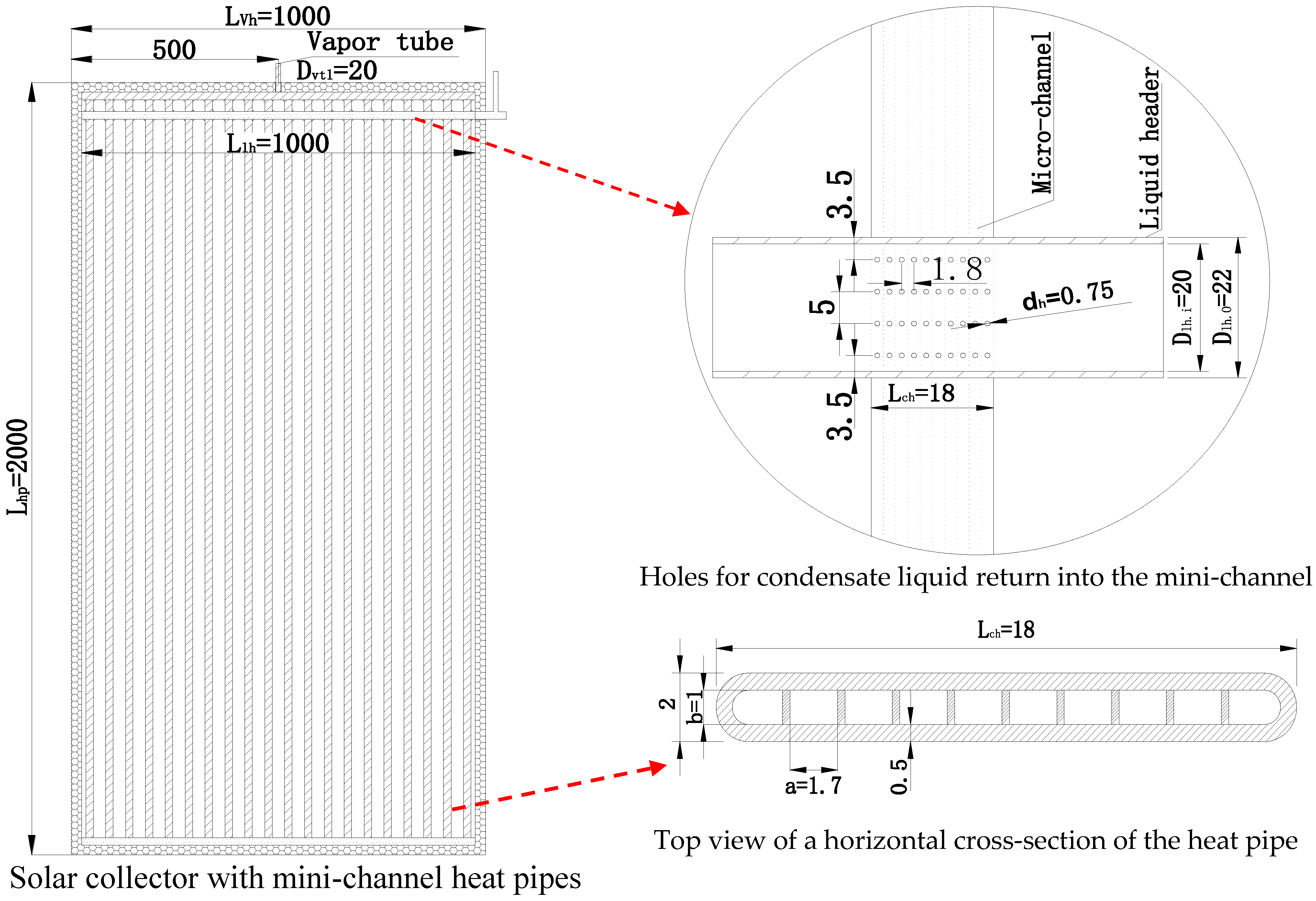
LHP System Description and Operation

The loop-heat pipe studied is described in Figure 1. The system is filled with the refrigerant R134a instead of water, which is chemically incompatible with the aluminium mini-channel. In fact, the water interaction with the aluminium can lead to a corrosion reaction without natural inhibition. This corrosion can generate non-condensable gas and then causes the breakage of the internal vacuum, which causes the non-functioning of the heat pipe [15]. The system is composed of the following main elements (Figure 1): the evaporator mini-channel, the condenser (shell and tube heat exchanger), the vapour transportation line (vtl), the liquid transportation line (ltl), the vapour header (vh), the liquid header (lh) and the liquid collector at the bottom of the evaporator. The fluid evaporated in the mini-channel is collected by the vapour header and transferred towards the heat exchanger via the vapour transportation line. After condensation at the heat exchanger, the liquid returns to the water header and enters the evaporator through small holes (Figure 1 and Figure 2). The natural fluid circulation in the loop-heat pipe system is governed by the pressure head between the condenser and the bottom of the evaporator. The solar collector is composed of 20 mini-channel heat pipes. Each mini-channel is composed of 10 ports (Figure 2). The condensed liquid enters into each port via four small holes with 0.75 mm diameter. The holes were placed on one side of each mini-channel port (Figure 2). They do not exist at the opposite side of the wall to avoid blocking the vapour flow because of a higher gravitational effect when the evaporator is inclined.
Table 1 summarises the first set of the LHP system components. These values will be used to experimentally study the thermal performance of the system.

3. Mathematical Equations for Heat-Transfer Limits

Five main heat-transfer limits that affect the system operation are considered, namely, the viscous limit QVL, sonic limit QSL, entrainment limit QEL, boiling limit QBL and pressure-drop limit QPL. These limits depend on the working fluid, the heat pipe dimensions, and the heat pipe operating temperature tv. The minimum value of these limits determines the maximum heat-transfer capacity of the LHP system. These limits are defined as following:

3.1. Viscous Limit QVL

The viscous limit occurs at low operating temperatures, when the viscous forces are larger than the pressure gradients [1]. This results in an insufficient pressure available to drive the vapour, and leads to the evaporator dry-out. The viscous limit at the evaporator can be expressed [16,17]:
Q VL , e = N ch   A v   r v   h fg ρ v P v 12   μ v   L hp .
By considering the liquid thickness in the micro-channel port, the vapour area Av can be expressed as the following:
A v = a × ( b δ lf ) ,
where ‘a’ is the mini-channel port width, ‘b’ is the mini-channel port height and δ lf is the liquid film thickness. This liquid film is formed by the condensate liquid from the four holes in the mini-channel (Figure 2). According to Imura et al. [18], the average film thickness with a current flow may be approximated to that without one because the average film thickness becomes a little larger. The liquid film thickness δ lf can be approximated as follows:
δ lf = ( 3 μ l 2 ρ l 2 g ) 1 / 3 Re 1 / 3   for   Re 400 ,
and
δ lf = 0.369 ( 3 μ l 2 ρ l 2 g ) 1 / 2 Re 1 / 2   for   Re > 400 ,
where Re is the Reynolds number, μl the liquid dynamic viscosity, g the gravitational acceleration. The Reynolds number is given by:
Re = ρ l U l δ lf μ l .
U l is the superficial velocity of the liquid film. Since the liquid flow through the holes of the microchannel depends of the driving force of the LHP, which is the pressure head, it is suitable to link it with the superficial flow. To consider this effect, the superficial velocity is linked to the pressure head by the following equation (it is simply expressed as the liquid flow throughout a hole caused by the pressure head):
U l = A h ( 2 g   H hp he ) 1 2 A l   ( 1 Cd 2 ( d h D lh ) ) ,
where Ah is the hole’s section, H hp he is the pressure head (height difference between the top of the evaporator and the heat exchanger), dh is the hole’s diameter and Dlh is the diameter of liquid header. The mass velocity Ul is assumed the same for the four holes, and then the film thickness is assumed the same along the adjacent wall. Al is the liquid film section expressed as following:
A l   = a × δ lf ,
where ‘a’ is the mini-channel port width. Cd [-], the discharge coefficient of the flow from the liquid head to the hole, is expressed as following [19]:
C d = 0.611   [ 87   ( μ l ρ l   d h g   H hp , he ) 1.43 +   ( 1 + 4.5   μ l ρ l   D H g   H hp , he ) 1.26 ] 0.7 .
The liquid thickness is calculated iteratively by assuming that the liquid mass flow from the liquid header is equal to the mass flow of the liquid film. Equation (1) can be applied to the other components of the loop, for example, the vapour transportation line Q v ,   vtl , the vapour header Q v ,   vh and the heat exchanger Q v ,   he . Thus, the minimum among these items would be the viscous limit of the system.
Q VL = min ( Q VL ,   vtl ,   Q VL ,   vh , Q VL ,   he , Q VL ,   e )

3.2. Sonic Limit QSL

The sonic limit is due to the fact that at low vapour densities the corresponding vapour flow rate in the heat pipe may result in very high vapour speed, and a choked vapour flow can occur in the vapour passage [1,16]. The sonic limit at the evaporator can be expressed as:
Q SL , e = N ch   A v ρ v h fg [ ( γ v   R v T v ) 2 ( γ v   + 1 ) ] 1 2 .
Equation (10) can be applied to the other components of the loop, for example, the vapour transportation line Q SL ,   vtl , the vapour header Q SL ,   vh and the heat exchanger Q SL ,   he . Thus, the minumum among these items would be the sonic limit of the system.
Q SL = min ( Q SL ,   vtl ,   Q SL ,   vh ,   Q SL ,   he , Q SL ,   e )

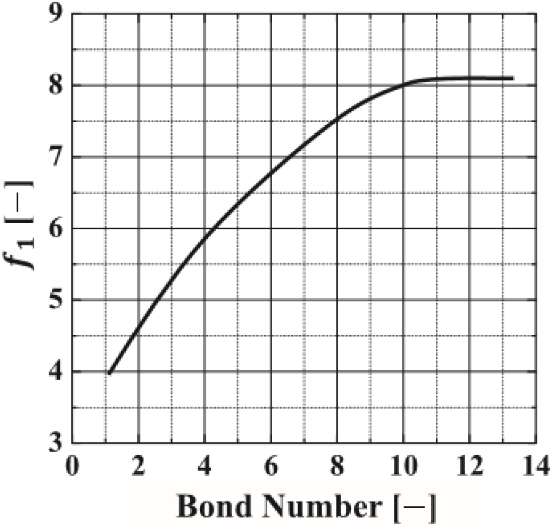
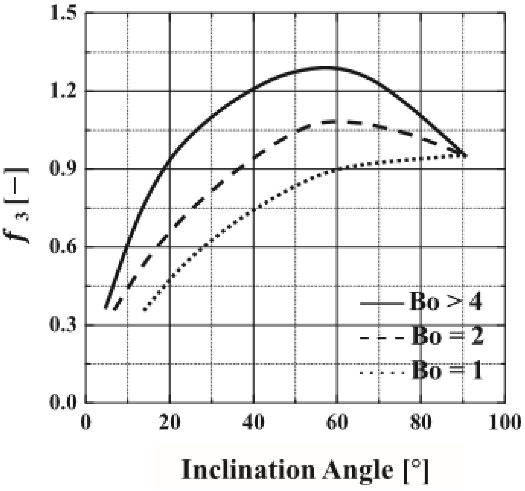
3.3. Entrainment Limit QEL

The entrainment limit refers to the case of high shear forces that are developed when the vapour passes over the liquid in the counter-flow direction, and liquid droplets may be entrained with the vapour towards the condenser. The entrainment limit exists in two parts of the system, in the evaporator and in the condenser. The entrainment limit for a wickless heat pipe can be expressed as follows [17]:
Q EL , hp =   N ch   f 1 f 2 f 3 ( A v )   h fg   ρ v 1 2   [ ( g   ( ρ l ρ v ) σ ) ] 1 2 ,
where f1 (Figure A1), f2 and f3 (Figure A2) are variables given in [16] and presented in Appendix A.
For the heat exchanger, the entrainment limit is given by:
Q EL , he = π   ( D he , i 2 δ w 2 ) 2 h fg   ( σ ρ v D w ) 0.5 ,
where D he , i is the heat-exchanger’s internal diameter, δ w is the liquid thickness (Appendix C (A11)) and D w is the condensed liquid hydraulic diamater. The smaller of Q EL , hp and Q EL , he represents the entrainment limit of the system, as shown:
Q EL = min ( Q EL , hp ,   Q EL , he ) .

3.4. Boiling Limit QBL

The boiling limit occurs when the applied evaporator heat flux is sufficient to cause nucleate boiling. This creates vapour bubbles that partially block the liquid return and can lead to evaporator dry-out. The boiling limit can occur at the evaporator and the condenser. The boiling limit for the evaporator can be expressed as follows [20]:
Q BL , hp = N ch   Ku   h fg   ρ v 1 2 ( ( g   ( ρ l ρ v ) σ ) ) 1 4 ,
where
Ku = 0.14   ( 1 T v T c ) 1 / 5 ( ρ l g b 2 σ ) 1 2 ( b Le ) 0.9 ( 1 + ( ρ v ρ l ) 1 4 ) 2 × ( 1 + ( 0.0125 T v T c + 1.01 ) β ) 2 .
The boiling limit for the heat exchanger can be expressed as follows [13,14]:
Q BL , he = 2   π   L hx λ w   T v   ( 2 σ r b ) h fg   ρ v   log ( D he , i D he , i 2 δ w ) ,
where λ w is the thermal conductivity of the water and rb is the critical radius of bubble generation and is assumed to be 2.54 × 10⁻⁷ m [14].
The smaller of Q BL , he and Q BL , he represents the boiling limit of the heat pipe system, as shown:
Q BL = min ( Q BL , hp ,   Q BL , he ) .

3.5. Pressure-Drop Limit QPL

The heat-transfer limit due to the pressure-drop limit QPL is reached when the condensate return level reaches the end of the condenser, and then any further increase of the heat-transfer rate causes the condensate to block part of the condenser, increasing the overall thermal resistance of the heat pipe [21]. The balance of the pressure drop is crucial for the loop operation; the total pressure head Δ P g must be superior to the total pressure drop Δ P t in the loop:
Δ P g Δ P t ,
where Δ P t = Δ P vtl , v + Δ P ltl , l + Δ P vh , v + Δ P lh , l + Δ P e + Δ P cond .
Δ P vtl , v is the vapour pressure drop in the vapour transportation line and Δ P ltl , l is the liquid pressure drop in the liquid transportation lines. Δ P vh , v is the pressure drop in the vapour header, Δ P lh , l is the pressure drop in the liquid header, Δ P e is the two phase pressure drop in the evaporator and Δ P cond (Pa) is the two-phase pressure drop in the condenser. By solving Equation (19), the heat-transfer limit due to the pressure drop QPL can be obtained. The items in Equation (19) can be addressed as follows.
The gravitational pressure Δ P g : ΔPg is the gravitational pressure caused by the height difference between the top of the heat exchanger and the bottom of the mini-channel evaporator, and can be expressed as [13,14]:
Δ P g = ρ l   g   ( H he / 2 + H he , hp + L hp   sin ( β ) ) ,
where H he is the height of the heat exchanger and H he , hp is the height difference between the outlet of the heat exchanger and the top of the evaporator. L hp is the evaporator length and β is the evaporator inclination.
The pressure drop in the evaporator ΔPe: The two-phase pressure drop in the mini-channel evaporator is expressed as follows [22]:
Δ P e = Δ P tp , F + Δ P tp , G + Δ P tp , A ,
where Δ P tp , F is the frictional pressure drop, Δ P tp , G (Pa) is the gravitational and Δ P tp , A (Pa) accelerational pressure drops as given in Appendix B.
The pressure drops in the vapour transportation line Δ Pvtl,v and the vapour header Δ Pvh,v: The vapour pressure drop in the vapour transportation line and the vapour header could be expressed as [23,24]:
Δ P vtl , v = ( C vtl ( f vtl , v Re vtl , v ) μ v 2 π ( D vtl / 2 ) 4 ρ v   h fg )   L vtl Q PL ,
where QPL is the pressure-drop limit, estimated at ~3.6. f vtl , v , and C vtl are given in Appendix C (A10).
The vapour pressure drops in the vapour header ΔPvh,v can be expressed by Equation (22) similarly.
Two-phase pressure drop in the condenser ΔPcond: The Muller-Steinhagen and Heck correlation [25] is used to estimate the two-phase pressure drop in the condenser. The correlation is given as:
dP dz = Λ   ( 1 x ) 1 / 3 + ( dP dz ) LO x 3 ,
where Λ and ( dP dz ) LO are given in Appendix D.
Total vapour pressure drop ΔPv: Total vapour pressure drop could be written as follows:
Δ P v   = Δ P e , v   + Δ P vtl , v   + Δ P vh , v   + Δ P he , v   .
Liquid pressure drop in the liquid header Δ P lh : The liquid pressure drop in liquid header can be expressed by the following equation:
Δ P lh = ( 8   μ l π ( ( D lf ) / 2 ) 4 ρ l   h fg )   L lh Q PL .
Liquid pressure drop in the liquid transportation line Δ P ltl , l can be expressed by the same form as Equation (25).

3.6. Algorithm for the Computer Model

The modelling approach used to calculate the heat-transfer limits of the LHP has been validated experimentally for a mini-channel heat pipe [26], and the mini-channel evaporator model used has been validated by much experimental data in the literature [22]. The algorithm used to compute the five heat-transfer limits is described as follows. Figure 3 presents the chart of the computer model.
  • Given the geometry of the solar LHP, technical parameters are presented in Table 1.
  • Given a certain operating temperature, the thermodynamic properties of the refrigerant are estimated.
  • Calculating the viscous limits at an appropriate region in the operation, and taking the minimum value as the viscous limit by Equations (1) and (9).
  • Calculating the sonic limit at an appropriate region in the operation, and taking the minimum value as the sonic limit by Equations (10) and (11).
  • Calculating the entrainment limits at an appropriate region in the operation, and taking the minimum value as the entrainment limit by Equations (12)–(14).
  • Calculating the boiling limits at an appropriate region in the operation, and taking the minimum value as the boiling limit by Equations (15), (17) and (18).
  • Running a numerical iteration to calculate the pressure-drop limit.
    (a)
    Given the initial value of QPL.
    (b)
    Gravity pressure is estimated Δ Pg by Equation (20).
    (c)
    Total pressure drop in the loop is estimated Δ Pt by Equation (19).
    (d)
    If [( Δ Pg Δ Pt)/ Δ Pg] < −0.5% (error allowance), then decrease QPL by 10.
    (e)
    If [( Δ Pg Δ Pt)/ Δ Pg] > −0.5% (error allowance), then increase QPL by 10.
    (f)
    If −0.5% ≤ [( Δ PG Δ Pt)/ Δ Pg] ≤ 0.5% (error allowance), heat balance is achieved and real value of QPL can be obtained.
  • Taking the minimum value, the five limits as the governing limit of the system operation.
  • Program stops.

4. Results and Discussion

4.1. The Impact of the Operating Temperature of the Mini-Channel Evaporator

By using the computer model, the influence of the operating temperature on the different heat-transfer limits was investigated. Table 2 presents the variation of the five heat-transfer limits (viscous, sonic, entrainment, boiling and pressure). For each given operating temperature, the governing heat-transfer limit (in bold in the table) is the minimum value of the five heat-transfer limits. At a given operating temperature, this minimum value represents the maximum heat-transport capacity of the system.
Table 2 shows that the viscous and sonic limits (QVL and QSL) increase with the operating temperature tv; however, the entrainment limit, the boiling limit and the pressure-drop limit decrease when the temperature is increased. For each operating temperature, the governing heat-transfer limit is the entrainment limit. The viscous limit QVL occurs in the vapour transportation line. The viscous limit reflects the difficulty of the vapour flow because of higher viscous forces, and is related to the Reynolds number. When the temperature increases, the Reynolds number, which is related to the working fluid thermodynamic properties, rises. Therefore, the vapour pressure difference becomes larger to overcome the viscous forces, and thus facilitates the vapour flow, and consequently the viscous limit increases. The sonic limit QSL also appears in the evaporator. The sonic limit increases with the vapour flow rate. Increasing the operating temperature would cause a smaller vapour density and a higher vapour flow rate. Therefore, the sonic limit of the system would be higher. The sonic limit increases and tends to a limit where any increase in temperature does not affect the vapor speed and tends to be constant. Otherwise, the increased vapour flow, because of the temperature rise, increases the possibility to entrain droplets from the evaporator towards the vapour transportation line, and thus the entrainment limit QEL that occurs in the mini-channel evaporator becomes lower. As with the entrainment limit, the boiling limit decreases when there is an increase in the operating temperature, because of the increase of the evaporation rate that can lead to the dry-out. This increased operating temperature increases the total pressure drop in the loop ΔPt because of higher flow velocity, and as a result, the heat-transfer limit QPL due to the pressure drop decreases.

4.2. The Impact of the Heat Pipe Aspect Ratio

Table 3 presents the effect of the aspect ratio on heat-transfer limits when the operating temperature tv is held at 50 °C and the height from the top of the absorber to the bottom of the condenser Hhp,he is 0.6 m. The aspect ratio (b/a) is the ratio of the mini-channel port height ‘b’ by its width ‘a’. Table 3 shows that all the heat-transfer limits increase with the aspect ratio. The increase of the aspect ratio by increasing ‘b’ on one hand creates higher vapour transporting space Av and thus higher evaporation rate, and on the other hand, leads to higher Bond number Bo (gravitational forces become more important compared to tension forces); as a result, the entrainment of the liquid droplets decreases and consequently the entrainment limit QEL increases. Low aspect ratios lead to decreased entrainment limits because the higher vapour flow, the small vapour space and the lower importance of gravitational forces (lower Bond number Bo) favour the entrainment of liquid droplets towards the condenser. As the aspect ratio increases, the vapour transportation space and the importance of gravitational forces (higher Bond number Bo) increase, enabling more liquid to return along the heat pipe, which causes higher boiling limitation QBL. As the vapour space increases, the shear forces decrease and the entrainment decreases slightly, tending to a constant value. Increasing the heat pipe ratio leads to a higher Reynolds number and thus lower viscous forces, and therefore, the LHP viscous limit QVL increases. The increase of the aspect ratio causes lower vapour speed, and as a result, the sonic limit increases. The sonic limit QSL first appears at the evaporator; as the vapour spaces increase, the sonic limit appears in the vapour transportation line and becomes constant. The fact that the aspect ratio increases allows more space for the vapour flow and a lower pressure drop, meaning that there is a higher heat-transfer limit QPL due to the pressure drop.

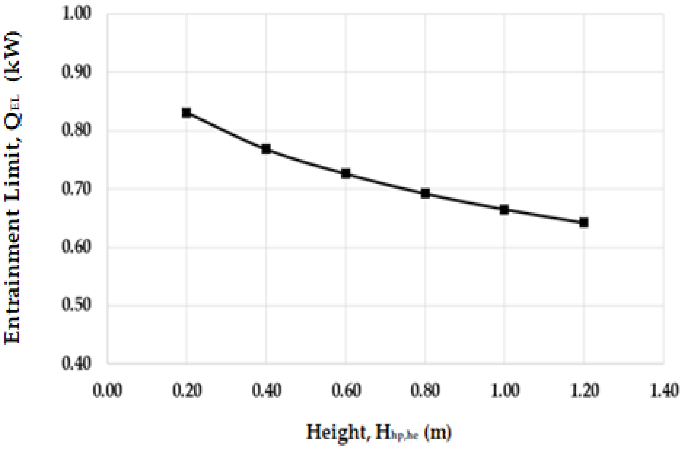
4.3. The Impact of the Condenser-to-Absorber Height Difference

Table 4 presents the effect of condenser-to-absorber height difference Hhp-he (Figure 1) on heat-transfer limits when the operating temperature tv is held at 50 °C and the aspect ratio at 0.58 (0.001/0.0017). It shows that the entrainment is the governing heat-transfer limit and it increases with an increase of the condenser-to-absorber height difference. The viscosity and sonic limits decrease with the height difference because of the reduction of the vapour space due the increase of the liquid film thickness δ lf . Figure 4 presents the evolution of the liquid thickness in function of the height Hhp,he.
The pressure limit remained unchanged because the impact height variation on the pressure drop was not considered.
An approximate linear relation is found and the increase of the height difference leads to an increase of the maximum heat-transfer capacity (Figure 5). This effect can be explained by the influence of gravity. A greater height difference leads to a higher gravitational force, which increases the liquid film thickness δ lf in the mini-channel evaporator.

4.4. Impact of the Individual Hole’s Dimension

For the loop-pipe system pipe with a 0.58 aspect ratio, an evaporator-to-condenser height difference Hhp,he of 0.6 m and the operating temperature of 50 °C, the impact of the individual hole’s diameter on the heat-transfer limits was investigated. As shown in Table 5, the hole diameter (Figure 2) has an influence on viscous limit, sonic limit and the entrainment limit. Increasing the hole’s diameter increases the liquid film thickness in the micro-channel and increased the possibility to entrain the liquid towards the condenser, and so the entrainment limit becomes lower. This increase of liquid film thickness decreases the vapour space and then causes the decrease of the sonic and viscous limits.

4.5. Impact of the Evaporator Inclination Angle

While maintaining an aspect ratio (b/a) of 0.58, an operational temperature tv of 50 °C, an evaporator length Lhp of 1.9 m, an evaporator-to-condenser height difference Hhp,he at 0.6 m and keeping the other LHP parameters the same, a change of the evaporator inclination angle β would influence the heat-transfer limits of the LHP. Table 6 shows that the entrainment limit is the governing limit, and increases with the evaporator inclination angle, while the other three limits all remain the same expect for the boiling limit, which increases and attains a maximum at 60° and then decreases. The entrainment limit increases between 0° to 60°, attains a maximum at 60° and afterwards decreases between 60–90° (Figure 6). The behaviour of this curve reflects the evolution of different parameters f1 and f3 of Equation (12) with the Bond number (Appendix A). Equation (12), used to estimate the entrainment limit of the wickless heat pipe (thermosyphon), is empirical, and many experimental studies show that the maximal heat-transport capacity occurs when the wickless heat pipe is at 60–80° to the horizontal, not vertical [17].
A higher inclination angle led to higher hydrostatic force, which improved the system capability in transporting the condensed liquid film flow, and thus led to increased heat flux while the other limits remained constant.

4.6. Impact of the Evaporator Length

While keeping the operational temperature, evaporator diameter, evaporator inclination angle, evaporator-to-condenser height difference and other LHP parameters constant, a change in the evaporator length can influence the heat-transfer limits of the LHP. Table 7 shows that by increasing the evaporator length, the viscous limit decreases while the boiling limit varies in the opposite trend. The viscous limit trend can be explained by the fact that the increase of the heat-pipe length increases the vapour distance, which could reduce the vapour volume flow rate and lead to a lower viscous limit. The sonic limit remains constant while the pressure limit increases slightly with evaporator length because of the pressure-drop decrease. The entrainment limit was found to be the main governing heat-transfer limit. The entrainment limit is constant because there is no interrelation (Equation (12)) between the entrainment limit and the heat-pipe length. Otherwise, the boiling limit became larger as the increased evaporator length led to an increased vapour space in the LHP, evaporation rate of the fluid and operating temperature.

5. Conclusions

This paper presented a numerical investigation of the heat-transfer limits for a novel solar LHP system using a mini-channel heat-pipe evaporator. Six main limits of the LHP, namely, the entrainment, viscous, boiling, sonic and pressure limits, were considered. The influence of the main mini-channel evaporator parameters (aspect ratio, length, inclination angle), the LHP operating temperature and the condenser-to-absorber height difference on the limits were assessed. The study showed that, for all varied parameters, the entrainment limit was the main governing heat-transfer limit of the novel solar LHP because of higher vapour flow and shear forces in the mini-channel evaporator. With the considered design of the LHP system and operational conditions, the system can achieve a heat-transfer limit of 725 W. Operation of the system with higher operating temperature enables higher heat-transfer capacity of the system. Similarly, the aspect ratio should be relatively larger and the condenser-to-absorber height difference should be low to avoid a higher liquid film thickness that could decrease the maximum heat-transport capacity of the system. The inclination of the mini-channel evaporator should enhance the maximum heat-transfer capacity of the system. The increase of the mini-channel length would lead an increased maximum heat-transfer capacity of the system. Finally, the computer model presented in this study can be used to optimise the heat-transfer capacity of the novel solar LHP.

Acknowledgments

The authors would acknowledge our appreciation to the financial supports from the EPSRC (EP/R004684/1) and Innovate-UK (TSB 70507-481546) for the Newton Fund—China-UK Research and Innovation Bridges Competition 2015 Project ‘A High Efficiency, Low Cost and Building Integrate-able Solar Photovoltaic/Thermal (PV/T) System for Space Heating, Hot Water and Power Supply’ and DongGuan Innovative Research Team Program (No. 2014607101008).

Author Contributions

Xudong Zhao conceived and proposed the research; Thierno M. O. Diallo, Min Yu, Jinzhi Zhou and Xudong Zhao participated to the novel Solar LHP system conception and design; Thierno M. O. Diallo, Min Yu, Jinzhi Zhou, Xudong Zhao and Jie Ji, conducted the numerical model development, simulations analysis and participated to write the paper; David hardy participated to the system analysis and the paper writing.

Conflicts of Interest

The authors declare no conflict of interest.

Nomenclature

Across-section[m2]
amini-channel width[m]
bmini-channel height[m]
BoBond number[-]
Cddischarge coefficient[-]
Ddiameter[m]
Dhhydraulic diameter[m]
fFanning friction factor[-]
f1factor 1[-]
f2factor 2[-]
f3factor 3[-]
ggravitational acceleration9.81 [m/s2]
Gmass velocity[kg/m2/s]
Hheight[m]
hfglatent heat of vaporisation[J/kg]
Llength[m]
MMach number[-]
Nnumber[-]
Nchnumber channel ports[-]
Ppressure[Pa]
ΔPpressure drop[Pa]
Qheat-transfer limit[W]
rbcritical radius of bubble generation[m]
Rspecific gas constant[J/(kg K)]
ReReynolds number[-]
t/Ttemperature[°C/°K]
Usuperficial velocity[m/s]
vvelocity[m/s]
xvapour quality[-]

Subscripts

Aaccelerational
BLboiling limit
chchannel
condcondenser
Ffrictional
eevaporator
ELentrainment limit
ffluid
Ffrictional
fgfluid gas
ggravity
Ggravitational
hhole
heheat exchanger
hpheat pipe
hp-heheat-pipe-to-heat-exchanger
iinner
kliquid or vapour
lfliquid film
lhliquid header
LOliquid only
ltlliquid transportation line
lliquid
oouter
pports
PLpressure limit
SLsonic limit
ttotal
tptwo-phase
vvapour
vhvapour header
VLviscosity limit
VOvapour only
vtlvapour transportation line
wwater

Greek Symbols

αvoid fraction
βinclination angle[o]
Δdifference
γratio of specific heat
λ thermal conductivity[W/(m·K)]
μdynamic viscosity[Pa·s]
ρdensity[kg/m3]
δ liquid film thickness[m]
σsurface tension[N/m]
v specific volume[m3/kg]

Appendix A

The factor f1 depends on the Bond number and can be obtained by the following curve:
Figure A1. Variation of factor f1 with the Bond number [27,28].
Energies 11 00148 g0a1
The factor f2 is function of the dimensionless parameter Kp obtained with the following equation [16]:
f 2 = K p 0.17   when   K p 4 × 10 4   and   f 2 = K p 0.17   when   K p > 4 × 10 4 ,
where
K p = P v g   ( ρ l ρ v ) σ 0.5 .
The factor f3 is a function of the inclination angle of the wickless heat pipe and the Bond number:
Figure A2. Variation of factor f3 with the inclination angle β and the Bond number [27,28].
Energies 11 00148 g0a2
The Bond number for the mini-channel port can be expressed as follows:
Bo = g   ( ρ l ρ v ) b 2 σ .

Appendix B

The accelerational pressure gradient is expressed as follows:
( dP dz ) A = G 2 d   dz [ v v x 2 α + v l ( 1 x ) 2 ( 1 α ) ] ,
where: α (-) is the void fraction, v v is the vapour specific volume, v l is the liquid specific volume, x [−] vapour quality, G is the mass velocity, and
α = [ 1 + ( 1 x x ) ( ρ v ρ l ) ] 1 .
The gravitational pressure gradient:
( dP dz ) G = [ α   ρ v + ( 1 α ) ρ l ]   g   sin ( β ) ,
where β is the channel inclination angle, ρ g is the gas density, ρ l is the liquid density. The frictional pressure gradient is given by:
( dP dz ) F = 2 f tp v l G 2 D h ( 1 + x v fg v l ) ,
where f tp is the two-phase frictionnal coefficient, f tp = 16   Re tp 1 for Retp < 2000;   f tp = 0.079   Re tp 0.25 for 2000 ≤ Retp < 20,000;   f tp = 0.046   Re tp 0.2 for Retp ≥ 20,000. Retp is the two-phase Reynolds number. The two-phase pressure drop is given by:
Δ P e =   0 L e [ ( dP dz ) F ( dP dz ) G ( dP dz ) A ] dz .

Appendix C

Re v , vtl = 4   Q PL π μ v   h fg D v , vtl   M v , vtl = 4   Q PL π D v , vtl 2 ρ v   h fg   ( R v t v γ v ) 0.5
Cvtl and fvtl with different conditions as follows:
  • If   Re v , vtl 2300   and   M v , vtl 0.2 , ( f v , vtl Re v , vtl ) = 16 , C v , vtl = 1 .
  • If   Re v , vtl 2300   and   M v , vtl > 0.2 , ( f v , vtl Re v , vtl ) = 0.038 ,   C v , vtl = ( 1 + ( γ v 1 2 ) M vtl , v 2 ) 0.5 .
  • If   Re v , vtl > 2300   and   M v , vtl 0.2 , ( f v , vtl Re v , vtl ) = 0.038 ,   C v , vtl = Re vtl , v 0.75 .
  • If   Re v , vtl > 2300   and   M v , vtl 0.2 ,
( f v , vtl Re v , vtl ) = 0.038 ,   C v , vtl = ( 1 + ( γ v 1 2 ) M vtl , v 2 ) 0.5 Re v , vtl 0.75 .
δ w = 0.93   ( v l μ l ) 2 / 3 σ l 1 / 6 ( ρ l g ) 0.5

Appendix D

The term Λ is a combination of the liquid- and vapour-phase pressure gradients and is given as:
Λ = ( dP dz ) LO + 2 [ ( dp dz ) VO ( dp dz ) LO ] x ,
where ( dP dz ) LO = f LO 2   G h , e 2 D ρ l   and   ( dp dz ) VO = f VO 2   G h , e 2 D ρ g .
The friction factors are given by the following relation:
f = 0.079   Re D 0.25
where the Reynolds number is defined using the total mass flux and the liquid or vapour viscosity, as appropriate.
Re D = GD μ k

References

  1. Launay, S.; Sartre, V.; Bonjour, J. Parametric analysis of loop heat pipe operation: A literature review. Int. J. Therm. Sci. 2007, 46, 621–636. [Google Scholar] [CrossRef]
  2. Bertela, M.; Prakash, J. Transport of thermal energy by a simple two-phase loop. Int. J. Energy Res. 1988, 12, 679–698. [Google Scholar] [CrossRef]
  3. Wang, Z.; Yang, W. A review on loop heat pipe for use in solar water heating. Energy Build. 2014, 79, 43–154. [Google Scholar] [CrossRef]
  4. Walker, A.; Mahjouri, F.; Stiteler, R. Evacuated Tube Heat-Pipe Solar Collectors Applied to the Recirculation Loop in A Federal Building; National Renewable Energy Lab.: Golden, CO, USA, 2004.
  5. Khairnasov, S.M.; Naumova, A.M. Heat pipes application to solar energy systems. Appl. Sol. Energy 2016, 52, 47–60. [Google Scholar] [CrossRef]
  6. Zhou, J.; Zhao, Z.; Ma, X.; Du, Z.; Fan, Y.; Cheng, Y.; Zhang, X. Clear-days operational performance of a hybrid experimental space heating system employing the novel mini-channel solar thermal & PV/T panels and a heat pump. Sol. Energy 2017, 155, 464–477. [Google Scholar]
  7. Hou, L.; Quan, Z.; Zhao, Y.; Wang, L.; Wang, G. An experimental and simulative study on a novel photovoltaic-thermal collector with micro heat pipe array (MHPA-PV/T). Energy Build. 2016, 124, 60–69. [Google Scholar] [CrossRef]
  8. Hopkins, R.; Faghri, A.; Khrustalev, D. Flat Miniature Heat Pipes with Micro Capillary Grooves. J. Heat Transf. 1999, 121, 102–109. [Google Scholar] [CrossRef]
  9. Zhou, J.; Zhao, Z.; Ma, X.; Zhu, Z.; Qiu, Z.; Ji, J.; Du, Z.; Yu, M. Experimental investigation of a solar driven direct-expansion heat pump system employing the novel PV/micro-channels-evaporator modules. Appl. Energy 2016, 178, 484–495. [Google Scholar] [CrossRef]
  10. Deng, Y.; Zhao, Y.; Quan, Z.; Zhua, T. Experimental study of the thermal performance for the novel flat plate solar water heater with micro heat pipe array absorber. Energy Proc. 2015, 70, 41–48. [Google Scholar] [CrossRef]
  11. Deng, Y.; Zhao, Y.; Wang, W.; Quan, Z.; Wang, L.; Yu, D. Experimental investigation of performance for the novel flat plate solar collector with micro-channel heat pipe array (MHPA-FPC). Appl. Therm. Eng. 2013, 54, 440–449. [Google Scholar] [CrossRef]
  12. Zhu, T.; Diao, Y.; Zhao, Y.; Li, F. Thermal performance of a new CPC solar air collector with flat micro-heat pipe arrays. Appl. Therm. Eng. 2016, 98, 1201–1213. [Google Scholar] [CrossRef]
  13. Wang, Z.; Zhao, Z. Analytical study of the heat transfer limits of a novel loop heat pipe system. Int. J. Energy Res. 2011, 35, 404–414. [Google Scholar] [CrossRef]
  14. Zhang, X.; Zhao, X.; Xu, J.; Yu, X. Study of the heat transport capacity of a novel gravitational loop heat pipe. Int. J. Low Carbon Tech. 2013, 8, 210–223. [Google Scholar] [CrossRef]
  15. Kuroda, M.; Chang, J.; Gwin, P.; Mongia, R. Development of aluminium-water heat pipes. In Proceedings of the 17th International Heat Pipe Conference (17th IHPC), Kanpur, India, 13–17 October 2013. [Google Scholar]
  16. Ochterbeck, J.M. Heat Pipes Heat Transfer Handbook; Wiley: New York, NY, USA, 2003; Volume 1. [Google Scholar]
  17. Reay, D.; Kew, P. Heat Pipes Theory, Design and Applications, 5th ed.; Elsevier: Oxford, UK, 2006; ISBN 978-0-7506-6754. [Google Scholar]
  18. Imura, H.; Kusuda, H.; Funatsu, S. Flooding velocity in a counter-current annular two-phase flow. Chem. Eng. Sci. 1977, 32, 79–87. [Google Scholar] [CrossRef]
  19. Swamee, P.K.; Swamee, N. Discharge equation of a circular sharp-crested orifice. J. Hydraul. Res. 2010, 48, 106–107. [Google Scholar] [CrossRef]
  20. Grooten, M.H.M.; van der Geld, C.W.M. The Effect of the Angle of Inclination on the Operation Limiting Heat Flux of Long R-134a Filled Thermosyphon. J. Heat Transf. 2010, 132, 05150. [Google Scholar] [CrossRef]
  21. Milanez, H.F.; Mantelli, M.B.H. Heat transfer limit due to pressure drop of two-phase loop thermosiphon. Heat Pipe Sci. Technol. Int. J. 2010, 1, 237–250. [Google Scholar]
  22. Kim, S.M.; Mudawar, I. Universal approach to predicting two phase frictional pressure drop for mini/micro-channel saturated flow boiling. Int. J. Heat Mass Transf. 2013, 58, 718–734. [Google Scholar] [CrossRef]
  23. Riffat, S.B.; Zhao, X.; Doherty, P.S. Analytical and numerical simulation of the thermal performance of ‘mini’ gravitational and ‘micro’ gravitational heat pipes. Appl. Therm. Eng. 2002, 22, 1047–1068. [Google Scholar] [CrossRef]
  24. Chi, S.W. Heat Pipe Theory and Practice; McGraw-Hill: New York, NY, USA, 1976. [Google Scholar]
  25. Müller-Steinhagen, H.; Heck, K. A Simple Friction Pressure Drop Correlation for Two-Phase Flow in Pipes. Chem. Eng. Process 1986, 20, 297–308. [Google Scholar] [CrossRef]
  26. Zhao, X. Investigation of a Novel Heat Pipe Solar Collector/CHP System. PhD Thesis, University of Nottingham, Nottingham, UK, 2003. [Google Scholar]
  27. Seo, J.; Bang, I.C.; Lee, J.Y. Length effect on entrainment limit of Large-L/D vertical heat pipe. In. J. Heat Mass Transf. 2016, 97, 751–759. [Google Scholar] [CrossRef]
  28. Engineering Science Data Unit. Heat Pipes-Performance of Two-Phase Closed Thermosyphons; Data Item No. 81038; ESDU: London, UK, 1981. [Google Scholar]
Figure 1. Schematic of the novel solar loop-heat pipe.
Energies 11 00148 g001
Figure 2. Solar collector with mini-channel heat pipes and condensate liquid pathway (units in mm).
Energies 11 00148 g002
Figure 3. Computer model flow chart.
Energies 11 00148 g003
Figure 4. Impact of the height Hhp-he on the liquid film thickness δlf.
Energies 11 00148 g004
Figure 5. Impact of the height Hhp,he on the entrainment limit.
Energies 11 00148 g005
Figure 6. Impact of the evaporator inclination angle on the entrainment limit.
Energies 11 00148 g006
Table 1. Design parameters of the LHP operation and heat exchanger.
ParametersNomenclatureValueUnit
Mini-channel port widtha0.0017m
Mini-channel port heightb0.001m
Evaporator lengthLhp1.9m
Number of mini-channel heat pipesNhp20-
Number of mini-channel portsNp10-
Total number of mini-channel portsNch200-
Operating temperature rangetv20–60oC
Evaporator-to-condenser height differenceHhp-he0.6m
Transportation line outer diameterDltl,o/Dvtl,o0.015m
Transportation line inner diameterDltl,i/Dvtl,i0.0174m
Liquid head lengthLlh1m
Liquid head diameterDlh0.022m
Vapour header lengthLvh1m
Hole diameterdh0.00075m
Transportation line lengthLltl/Lvtl1/1m
Heat exchanger central tube total lengthLhe5m
Table 2. Impact of the operating temperature.
Operating Temperature tv (°C)Viscous Limit QVL (kW)Sonic Limit QSL (kW)Entrainment Limit QEL (kW)Boiling Limit QBL (kW)Pressure-Drop Limit QPL (kW)
25183.0081.800.8882.8924.40
30233.0091.900.8852.8822.70
40350.00102.000.8012.7219.70
45409.00107.000.7672.6218.30
50465.00110.000.7252.5017.01
55515.00111.000.6772.3615.01
60555.00111.050.6232.1914.46
Table 3. Impact of the aspect ratio.
Aspect Ratiob (mm)/a (mm)Viscous Limit QVL (kW)Sonic Limit QSL (kW)Entrainment Limit QEL (kW)Boiling Limit QBL (kW)Pressure-Drop Limit QPL (kW)
0.29(0.0005/0.0017)3.5221.700.1261.164.01
0.58(0.001/0.0017)465.00110.000.7252.5017.01
0.86(0.0015/0.0017)2730.00122.001.4553.8820.20
1.15(0.002/0.0017)8230.00122.502.2905.2930.50
1.44(0.0025/0.0017)18,400.00122.502.3706.7154.40
1.73(0.003/0.0017)38,800.00122.502.3718.1498.19
Table 4. Impact of the condenser-to-absorber height difference.
Height Hhp,he (m)Viscous Limit QVL (kW)Sonic Limit QSL (kW)Entrainment Limit QEL (kW)Boiling Limit QBL (kW)Pressure-Drop Limit QPL (kW)
0.20699.00122.000.8312.5017.01
0.40551.00117.000.7682.5017.01
0.60465.00110.000.7252.5017.01
0.80404.00105.000.6922.5017.01
1.00359.00101.000.6652.5017.01
1.20322.0097.800.6422.5017.01
Table 5. Impact of the condenser-to-absorber height difference.
Hole Diameter dh (mm)Viscous Limit QVL (kW)Sonic Limit QSL (kW)Entrainment Limit QEL (kW)Boiling Limit QBL (kW)Pressure-Drop Limit QPL (kW)
0.301090.00122.500.962.5017.01
0.50689.00122.000.832.5017.01
0.75465.00110.000.732.5017.01
1.00141.0074.200.492.5017.01
Table 6. Impact of the evaporator inclination angle.
Angle β (°)Viscous Limit QVL (kW)Sonic Limit QSL (kW)Entrainment Limit QEL (kW)Boiling Limit QBL (kW)Pressure-Drop Limit QPL (kW)
10465.00110.000.290146.00017.01
20465.00110.000.418146.00017.01
30465.00110.000.543145.60017.01
40465.00110.000.617127.30017.01
50465.00110.000.772102.40017.01
60465.00110.000.85677.40017.01
70465.00110.000.73252.40017.01
80465.00110.000.72927.40017.01
90465.00110.000.7252.50017.01
Table 7. Impact of the evaporator length.
Evaporator Length Lhp (m)Viscous Limit QVL (kW)Sonic Limit QSL (kW)Entrainment Limit QEL (kW)Boiling Limit QBL (kW)Pressure-Drop Limit QPL (kW)
0.501310.00100.000.662.1916.79
1.00657.00100.000.662.3416.94
1.50488.00100.000.662.4416.98
1.90465.00100.000.662.5017.01

