Analysis of Combined Cycle Power Plants with Chemical Looping Reforming of Natural Gas and Pre-Combustion CO2 Capture


1
Department of Energy and Process Engineering, Norwegian University of Science and Technology, 7491 Trondheim, Norway
2
SINTEF Materials and Chemistry, 7034 Trondheim, Norway
*
Author to whom correspondence should be addressed.
Energies 2018, 11(1), 147; https://doi.org/10.3390/en11010147
Submission received: 3 December 2017
/
Revised: 4 January 2018
/
Accepted: 5 January 2018
/
Published: 8 January 2018
Abstract
:In this paper, a gas-fired combined cycle power plant subjected to a pre-combustion CO2 capture method has been analysed under different design conditions and different heat integration options. The power plant configuration includes the chemical looping reforming (CLR) of natural gas (NG), water gas shift (WGS) process, CO2 capture and compression, and a hydrogen fuelled combined cycle to produce power. The process is denoted as a CLR-CC process. One of the main parameters that affects the performance of the process is the pressure for the CLR. The process is analysed at different design pressures for the CLR, i.e., 5, 10, 15, 18, 25 and 30 bar. It is observed that the net electrical efficiency increases with an increase in the design pressure in the CLR. Secondly, the type of steam generated from the cooling of process streams also effects the net electrical efficiency of the process. Out of the five different cases including the base case presented in this study, it is observed that the net electrical efficiency of CLR-CCs can be improved to 46.5% (lower heating value of NG basis) by producing high-pressure steam through heat recovery from the pre-combustion process streams and sending it to the Heat Recovery Steam Generator in the power plant.
1. Introduction
Over the last century, CO2 emissions through burning of fossil fuels have contributed most to global warming. The projections for usage of fossil fuels are incompatible with levels required to stabilise CO2 concentrations at safe levels in the atmosphere. Hence, the need for CO2 capture and storage (CCS) from large point source emissions, like power plants, has been well debated and agreed upon. CCS is expected to contribute one sixth of the total CO2 emission reductions by the year 2050 [1].
The methods for CO2 capture in power plants have been categorized into post-combustion, pre-combustion and oxy-fuel combustion. A detailed review about their development has been presented by Boot-Handford et al. [2] and Kenarsari et al. [3]. In the current study, the focus is on pre-combustion capture and chemical looping reforming (CLR) in a natural gas (NG) fired power plant. Although post-combustion amine absorption is the most mature technology, chemical looping processes, with their ability to inherently separate CO2, possess a high thermodynamic potential (less exergy destruction) with a low energy consumption for the capture of CO2. Chemical looping processes like chemical looping combustion (CLC) and CLR use metallic oxygen carriers to convert the chemical potential of fossil fuels into work. The concept was proposed by Richter and Knoche [4] and a first-of-its-kind CLC-based power generation cycle was presented by Ishida and Jin [5], Ishida, et al. [6]. CLC converts the chemical energy of the fossil fuel into heat at relatively low temperatures (T ≈ 800–1100 °C) [7,8,9]. On the other hand, CLR converts the chemical energy of fossil fuel into a H2 rich fuel, which combusts and results in streams of higher temperature (T ≈ 1400–1500 °C) [10].
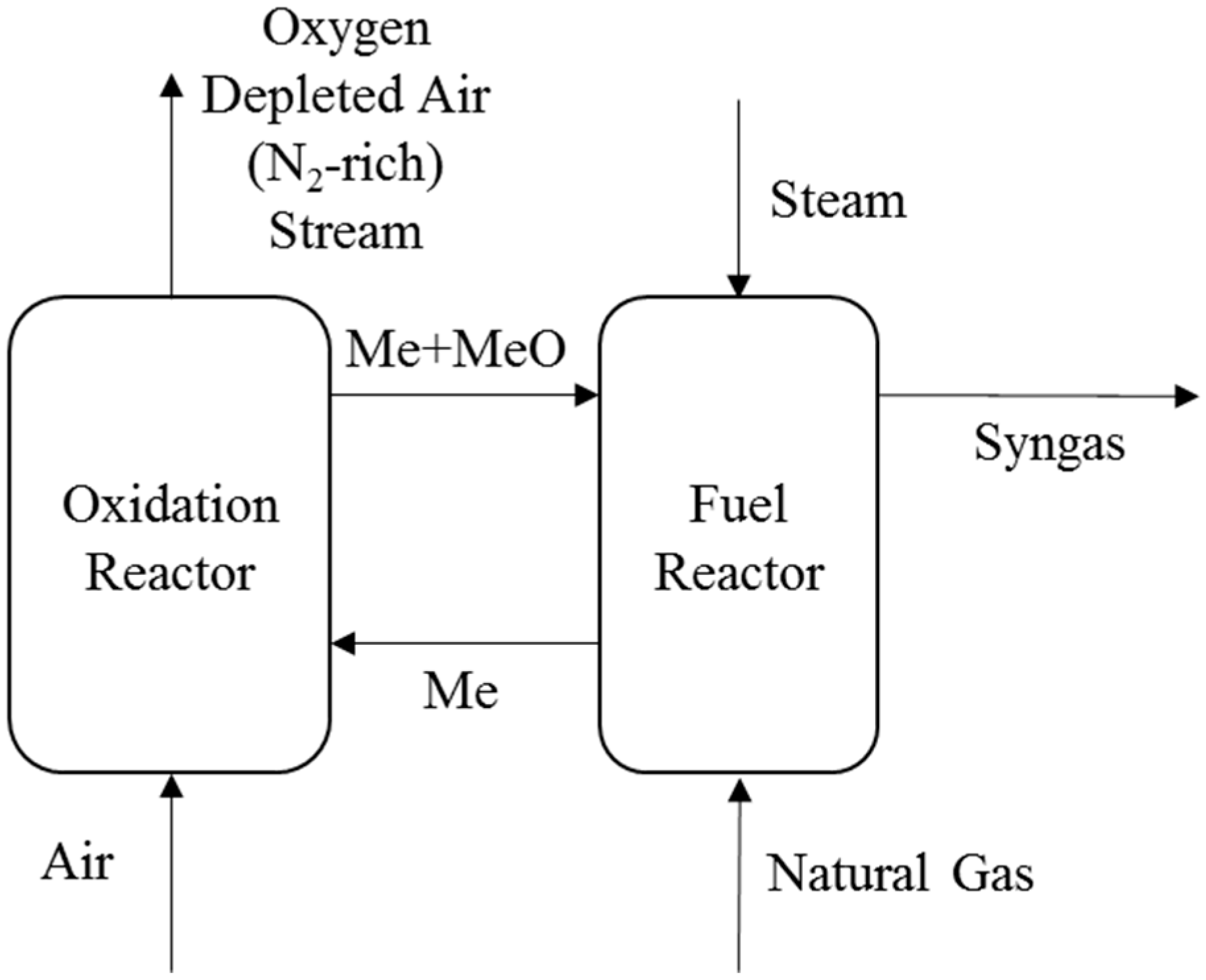
A schematic of the basic CLR process is shown in Figure 1. Compressed air reacts with metallic oxygen carrier in the oxidation reactor, which results in oxidized metallic oxygen carrier alongside an oxygen depleted air stream (N2-rich stream). The oxidized metallic oxygen carrier reacts with NG in the fuel reactor in the presence of steam to produce syngas. The reduced oxygen carrier is circulated back to the oxidation reactor. A FeO-Fe3O4 system has been assumed as the oxygen carrier in the analysis presented in this paper. Excess oxygen carrier is circulated between the two interconnected reactors to transfer heat from the oxidation reactor to the fuel reactor for endothermic reactions. The overall process is self-sustaining and requires no external heating. The CLR is generally operated above atmospheric pressures. Some practical knowledge of operating high pressure circulating reactors stems from the successful operation of a pressurized fluidized combustion bed power plant in Värtan, Sweden [11].
In the context of chemical looping processes, numerous studies have been reported in the literature on the choice of oxygen carrier [12,13], reactor scale experimental analysis and reactor modelling [14,15,16,17,18,19,20]. The focus in the mentioned literature was on hydrogen production and reactor performance. Studies have also been carried out on analysis of power generation processes with pre-combustion capture with Ca-Cu looping [21], auto-thermal reforming [22,23,24,25,26,27] and steam-methane reforming [28]. Analysis of chemical looping systems with more focus on hydrogen production from NG has been reported by Spallina et al. [29], Kathe et al. [30], Diglio et al. [31], Antzara et al. [32], and Cormos et al. [33]. Recently studies have also been reported on novel concepts to produce hydrogen using fixed beds in sorption enhanced steam methane reforming [34] and quasi-autothermal process (process concept combining CLC and steam methane reforming) [35].
The first of its kind plant-scale analysis of a NG based combined-cycle power plant with CLR, water gas shift (WGS), CO2 capture and compression was presented by the current authors in a previous paper [10]. This type of power plant is denoted as a CLR-CC plant. The net electrical efficiency for the process was estimated to be 43.1% (lower heating value of NG basis). The focus of the study presented in Nazir, Bolland and Amini [10] was on integration of the CLR process in a combined-cycle power plant with CO2 capture. The current paper goes further with analyses of the behaviour and performance of the CLR-CC power plant at different CLR design pressures and with different heat integration options. The methods used in this paper are similar to the methods used by Nazir, Bolland and Amini [10], but the scope and analysis presented in this paper are very different and is focussed on identifying design conditions for the CLR-CC process and improving its net electrical efficiency. The net electrical efficiency reported by Nazir, Bolland and Amini [10] is also different from the current study as there have been improvements in the CLR-CC process (especially multi-stage compression of the diluent N2-rich stream) in this paper. The pressure for the CLR is identified as a parameter, which not only affects the performance of the reactor, but also is important for the integration of CLR with the power generation process. The sensitivity study for pressure inside the CLR gives an insight into making decisions for design of the CLR-CC process. Improvement in the process efficiency with different heat integration options are also discussed in this paper. Section 2 of the paper describes the base case design of the CLR-CC process. Section 3 describes the methodology and the assumptions used in the study. The results and discussion are presented in Section 4 and conclusions in Section 5.
2. Process Description
This paper deals with a sensitivity study for a natural gas-based power plant with pre-combustion CO2 capture and CLR. NG is reformed and converted to H2 rich fuel alongside being subjected to CO2 capture. The decarbonized H2-rich fuel is then combusted in the gas turbine system to produce power. This section presents a brief description of the base case CLR-CC process, where the design pressure for CLR is 18 bar, and all the heat from the cooling of process streams is used to produce saturated low pressure (LP) steam. The selection of different process systems have been discussed by Nazir, Bolland and Amini [10]. The evaluated alternatives to the base case, with different design pressures for the CLR and heat integration options, are explained in the methodology section.
Figure 2 shows a schematic of the CLR-CC process where the design pressure in the oxidation reactor of the CLR is 18 bar (base case). Compressed air at 18 bar is reacted with the oxygen carrier in the oxidation reactor of the CLR. 12% by mass of the air bled at the compressor discharge in the gas turbine of the power plant is mixed with the compressed air stream from a separate air compressor before entering the oxidation reactor. The oxygen carrier is oxidized and the depleted air stream (N2-rich stream) is released which contains mainly nitrogen. NG is partially oxidized by the oxygen carrier in the presence of steam. The N2-rich stream from the oxidation reactor is expanded in a turbine (efficiency 90%) and cooled while producing LP steam and pre-heating the fuel entering the gas turbine system. A fraction of the cooled N2-rich stream is compressed (compressors with 90% efficiency) in two stages and used as diluent in the gas turbine, while the remainder is vented out to the atmosphere. The inter-stage cooling of the N2-rich stream during compression also produces LP steam. The N2-rich stream can be treated in other ways, i.e., have only a fraction of the N2-rich stream expanded in the turbine and the remainder of the N2-rich stream can be cooled and compressed before using it as diluent in the Gas Turbine system. The authors found that the efficiency penalty is least when the N2-rich stream is treated the way addressed in this paper. The efficiency penalty in treating the N2-rich stream is also a factor of the turbine and compressor efficiencies, but a detailed study of this is not within the scope of the current paper.
The syngas from the fuel reactor contains carbon monoxide which to a large extent is converted to CO2 through a WGS process. The WGS is carried out in two steps, at high (400 °C) and low temperature (200 °C) [36]. The high temperature WGS (HTS) and low temperature WGS (LTS) product streams are cooled down to the required temperature and LP steam is generated through heat recovery. The product stream from the LTS is cooled down to 50 °C and is sent to the CO2 capture section. CO2 is captured in the absorber using an activated methyl diethanolamine (a-MDEA) solution. The CO2 rich amine is then sent to the stripper for regeneration of amine. The captured CO2 is compressed to 110 bar and is ready for transportation and storage. The H2-rich stream from the top of the absorber is used as fuel in the power generation process. A fraction of the LP steam produced from cooling of the N2-rich stream, syngas and WGS reaction, is utilized in the reboiler of the stripper in the CO2 capture section. Remaining LP steam is expanded in a separate steam turbine (additional LP steam turbine with 85% efficiency) to generate power. The condensed water from the reboiler is converted to steam by utilizing heat from the syngas. The condensate from the additional LP steam turbine is sent to the condenser in the power plant.
The H2-rich stream is compressed (compressor with 85% efficiency), pre-heated and mixed with the diluent N2-rich stream before being combusted with air in a GE 9371FB gas turbine system. The selected gas turbine is robust to changes in fuel type and also supports fuel which is rich in hydrogen [23,37]. The gas turbine exhaust is passed through the Heat Recovery Steam Generator (HRSG) to produce steam for the steam cycle before being released to the atmosphere. The steam cycle consists of three pressure level steam generators and steam turbines at 166 bar, 32.7 bar, 3.4 bar for high pressure (HP), medium pressure (MP) and low pressure (LP) steam, respectively. The water and steam mixture from the steam turbine (ST) system is condensed in a condenser to prepare feed water for the steam cycle. A natural draft cooling tower supplies the cooling water to the condenser and it fulfils the cooling water requirement in the entire process.
The power plant comprises of two gas turbines (GT), two HRSGs with one steam turbine system comprising of one high pressure steam turbine, one medium pressure steam turbine and two low pressure turbines. The chosen power plant configuration is the same as a natural gas combined cycle (NGCC) plant without CO2 capture as reported by the European Benchmarking Task Force (EBTF) [37]. The HRSG, as shown in Figure 3, comprises of low, medium and high pressure economizers, boilers and super-heaters. The exhaust from the GT provides heat to produce superheated HP, MP and LP steam, which is expanded in the respective turbines to produce power. The MP steam also undergoes a reheat before being expanded in the MP steam turbine. In the base case design described above, the additional steam generated from the heat of reforming and shift reactions is not added to the HRSG. Generating steam at high pressure and mixing it with streams in the HRSG improves the process efficiency. Analysis of cases with different heat recovery and integration options is discussed in the following sections.
3. Methodology
To analyse the CLR-CC process, three different process simulation tools were used to establish the mass and heat balance calculations. Thermodynamic equilibrium conditions are assumed in all components. The air compressor and CLR were simulated using Aspen Plus V8.6 (Aspen Technology, Inc., Bedford, Massachusetts, USA). The equilibrium conditions for gas-solid reactions in the CLR can be simulated in Aspen Plus, but not in Aspen HYSYS since the thermodynamic property data for solids is in Aspen Plus [38]. The WGS, CO2 capture and CO2 compression processes were simulated using Aspen HYSYS V8.6 since it provides an option to use the Acid Gas thermodynamic model which is well suited for amine systems [39]. The combined cycle power plant was analysed using the Thermoflex component of the Thermoflow suite V26 (Thermoflow Inc., Southborough, MA, USA), since Thermoflow contains a database of standard commercial gas turbine systems [40]. The models were linked using Microsoft Excel (Microsoft Corporation, Redmond, Washington, USA). Net electric efficiency on a LHV basis, is chosen as the parameter that indicates the performance of the power plant. The net electric efficiency (η) of the process is defined as:
The Peng Robinson model was used to estimate the equilibrium conditions in CLR and WGS processes [14]. The Gibbs Reactor module is used to simulate the conditions in the oxidation and fuel reactors of the CLR. In the base case design, the Oxidation Reactor of CLR is operated at a pressure close the pressure of the compressor bleed from the GT system, which is 18 bar. Compressor bleed flow is 12% by mass of the air entering the GT system. The percentage of air bled from the compressor of the gas turbine system can be varied and the effect on the overall performance can be observed. A sensitivity on the percentage of the air bled is not in scope of this study. The remainder of the air needed is taken from the atmosphere and compressed using a separate air compressor, which operates with a polytropic efficiency of 90.9%. A steam to carbon ratio of 0.9 is assumed at the inlet of the fuel reactor. Steam is extracted from the MP Steam Turbine in the power plant. The air flow and the oxygen carrier circulation is adjusted to get a 99% conversion of CH4 at equilibrium in the fuel reactor alongside limiting the oxidation reactor outlet temperature to 1200 °C. At such high temperatures, there exists a risk of agglomeration and sintering of oxygen carrier material that affects the techno-economic performance of the reactor [41]. Anyhow, in this paper the agglomeration and sintering effects of the oxygen carrier is neglected as the current paper focuses on the thermodynamic behaviour of the overall process. The pressure drop in the oxidation and fuel reactors is 5%. The compositions, temperatures and pressures for air and NG has been considered from EBTF report [37].
The HTS and LTS processes were simulated using the equilibrium reactor module in Aspen HYSYS. A pressure drop of 3% was assumed in each of the WGS steps in this study. The heat exchangers between the processes have a 2% pressure drop on the gaseous stream and 0.4 bar pressure drop when the fluid flowing is liquid [37]. Saturated LP steam at 3.8 bar is produced when process streams are cooled. The CO2 capture section consists of an absorber and a stripper, where 45% by mass a-MDEA is used as a solvent. The a-MDEA solvent serves well for CO2 capture for moderate partial pressures of CO2 at the absorber inlet [42]. The design conditions in the absorber and regenerator to capture CO2 and regenerate the amine are adjusted to maintain a CO2 capture rate of 95% across the absorber. Saturated LP steam at 3.8 bar is used in the reboiler of the stripper to regenerate the amine. The captured CO2 is compressed and pumped to 110 bar through a compression cycle proposed by EBTF [37].
The combined cycle power plant has been modeled using the Thermoflex component of Thermoflow suite. The GT is run at 100% load with a LHV fuel input of approximately 1.55 GW at the GT inlet and 1430 °C as the Turbine Inlet Temperature (TIT). Based on these constraints, the amount of fuel input is estimated. To compensate for the compressor bleed in the GT system, which is used in the oxidation reactor in CLR, the same amount of N2-rich stream, coming as an outlet from oxidation reactor, is added to the GT combustor as a diluent.
In the current study, the process is analyzed at different CLR design pressure conditions to understand its effect on the net electrical efficiency of the CLR-CC process. Four different heat integration options have also been analysed to improve the efficiency of the base case process. The modifications in the process with respect to the base case and assumptions for different cases are described in Section 3.1 and Section 3.2.
3.1. Different Design Pressures for the Chemical Looping Reforming
The sensitivity study is carried out for the process at six different design pressures for CLR (including the base case), without changing the design of the process significantly. P5, P10, P15, base case (P18), P25 and P30 represent the cases where the pressures at the inlet of the oxidation reactor are 5, 10, 15, 18, 25 and 30 bar, respectively. In cases P5, P10 and P15, the air bled from the compressor in the GT system is at 5, 10 and 15 bar, respectively. The compressor discharge pressure in the GT system is 18.6 bar. Hence, in cases P18, P25 and P30, the air bled from the compressor is at the discharge pressure. In cases P25 and P30, an additional air compressor is added to the process to raise the pressure of the air bleed stream from the discharge pressure to the respective pressure at the inlet of the oxidation reactor in CLR. The efficiency of the additional air compressor in cases P25 and P30 is similar to the efficiency of the air compressor that is compressing atmospheric air used in the oxidation reactor. The HRSG design was not changed while studying the effect of pressure in CLR on the efficiency of the process.
3.2. Options for Heat Integration
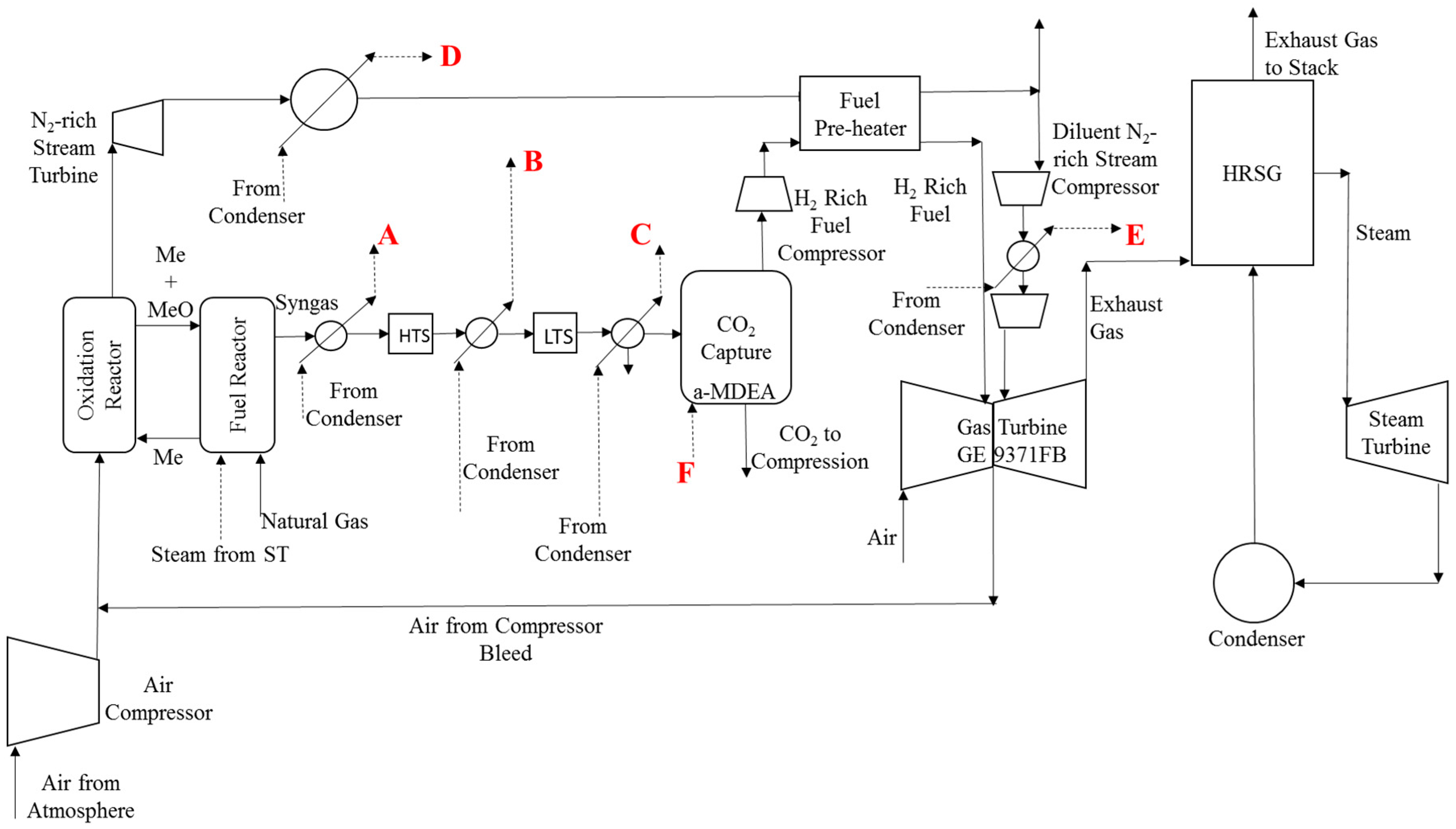
Options for heat integration, the base case followed by four other cases is described below. Figure 4 shows the schematic of the GSR-CC process with the points where steam is produced from heat recovery from the process streams. Table 1 shows the type of steam produced from heat recovery at the respective points shown in Figure 4. In all the cases considered to study different heat integration options, the process conditions in CLR, WGS, CO2 capture and compression sections are same as in the base case, except for the quality of steam prepared from cooling of process streams. The conditions of the steam produced are based on the point at which it is integrated in the steam cycle and the pressure drops encountered in economizers, boilers and super-heaters in the HRSG.
Base Case: The stream data including the compositions, temperatures and pressures of each process stream for the base case are shown in Table 2 This base case is the same as case P18 (base case) defined earlier when cases to study the sensitivity with respect to pressures have been defined. Syngas, HTS and LTS product streams, N2-rich stream from turbine and diluent N2-rich stream during the inter-stage compression is cooled to produce saturated LP steam at 3.8 bar. A fraction of the saturated LP steam is used in the reboiler of the CO2 capture section and the remainder of it is sent to steam turbine to produce work.
Case 1: Syngas at 984 °C is cooled to 400 °C to produce superheated HP steam at 166 bar and 600 °C, which is mixed with the HP steam from the HRSG before being expanded in the HP turbine. The N2-rich stream from the turbine is cooled to produce superheated MP steam at 36.4 bar and 371 °C, which is mixed with MP steam before the reheat, and sent to the HRSG. Saturated LP steam at 3.8 bar is prepared from cooling of the LTS product and is sent to the HRSG for LP superheating. Heat from the HTS product and diluent N2-rich stream from the inter-stage cooling of the compressor is used to produce saturated LP steam at 3.8 bar for the reboiler.
Case 2: Syngas is cooled from 984 °C to 400 °C to produce saturated HP steam at 174.4 bar, which is mixed with saturated HP steam from the HP boiler in the HRSG, and sent to the HP super heater. The N2-rich stream from the turbine is cooled to produce superheated MP steam at 36.4 bar and 371 °C, which is mixed with MP steam before the reheat, and sent to the HRSG. Saturated LP steam at 3.8 is prepared from cooling of the LTS product and is sent to the HRSG for LP superheating. Heat from HTS product and the diluent N2-rich stream from the inter-stage cooling of the compressor is used to produce saturated LP steam at 3.8 bar for the reboiler.
Case 3: Syngas from the CLR and N2-rich stream from the turbine is cooled to produce saturated HP steam at 174.4 bar, which is mixed with HP steam from the HP boiler in the HRSG, and then sent to the HP super heater. Saturated LP steam is prepared from cooling of the LTS product and is sent to the HRSG for LP superheating. Heat from the HTS product and diluent N2-rich stream from the inter-stage cooling of the compressor is used to produce saturated LP steam at 3.8 bar for the reboiler.
Case 4: Syngas, N2-rich stream, diluent N2-rich stream in the inter-stage compression and HTS product are cooled to produce saturated HP steam at 174.4 bar. This saturated HP steam is mixed with the HP steam from the HP boiler in the HRSG and sent to the HP super heater. LTS product is cooled to produce saturated LP steam at 3.8 bar, which is mixed with the LP steam from the LP boiler, and then sent to the LP super heater. Superheated LP steam is extracted from the inlet of the LP turbine in the steam cycle, and is used in the reboiler.
4. Results and Discussion
4.1. Sensitivity Study for Pressure in Chemical Looping Reforming
A sensitivity study was carried out to understand the performance at different design pressures for the CLR. The process is analysed at 5, 10, 15, 18, 25 and 30 bar pressure in the CLR represented as cases P5, P10, P15, base case (P18), P25 and P30, respectively. As discussed in the previous sections, in the base case, the design pressure for CLR is 18 bar, which is close to the pressure of air bleed at the compressor discharge from the gas turbine system in the power plant. The main results for the sensitivity study at different design pressures in the CLR are presented in Table 3. The power produced or consumed by different components in the process is given as a percentage of the total LHV of the NG fuel input to the process. The negative (“−”) sign indicates that the respective component consumes power and hence acts as a penalty on the efficiency of the process. As seen in Table 3, the power generated from the gas turbine system is high at lower design pressures (5–15 bar) for CLR, since the air bleed from the compressor is at lower pressure, which requires less compression power compared to the air bleed at the compressor discharge. Similarly, net power generated from the steam cycle is high at lower design pressures for CLR (5–18 bar) since it requires steam for reforming at lower pressures which is extracted from the MP steam turbine, and hence lowering the power loss from MP turbine.
The power generated from the N2-rich stream turbine increases with an increase in design pressures in the CLR since the pressure ratio in the turbine is high. At higher design pressures in the CLR, more heat is present in the process streams to produce LP steam, which is expanded in the additional LP steam turbine resulting in higher power output from it. The efficiency penalty from the air compressor is high at higher pressures. For pressures more than the compressor discharge pressure of air bleed from the gas turbine, as in cases P25 and P30, an additional air compressor is required to compress the air bleed from the discharge pressure to the required design pressure for the CLR. The efficiency penalty for the air compressor for cases P25 and P30 in Table 3 includes the penalty due to the additional air compressor. The energy penalty due to the H2-rich fuel compressor is less at higher design pressures for the CLR, since the H2-rich fuel stream is coming out of the absorber in CO2 capture section at higher pressures. There is no significant difference in energy penalty due to the N2-rich stream compressor, the CO2 compressors and pump, pump for regenerated amine and auxiliaries in the cases shown in Table 3.
All the components listed in Table 3, except the Gas Turbine, Steam Turbine and Auxiliaries, would be added to adapt a NGCC plant for pre-combustion capture of CO2. Another interesting point to notice is that at lower pressures (5–15 bar) for CLR, the sum of percentage of LHV of NG fuel for additional components is negative and hence a higher penalty on the efficiency of the process. At higher pressures (18–30 bar), the sum of the percentage of LHV of NG for additional components is positive. Anyhow, the sum is very close to zero when the design pressure for CLR is 18 bar, which is very close to the pressure of the air bleed from the compressor discharge in the GT. This is mainly because the power output from the N2-rich stream turbine and the additional LP steam turbine nullifies the penalty from compressors for the diluent N2-rich stream, H2-rich fuel, air and CO2 alongside pump for the amine and other auxiliaries. Although the efficiency of the compressors and turbines is going to affect the outcome from each component, the efficiencies were assumed constant in all the cases presented in this paper. The net electrical efficiency of the CLR-CC process is high at higher design pressures for the CLR. Anyhow, for pressures more than 18 bar, an additional air compressor needs to be included in the process to compress the air bleed from discharge pressure to the required pressure for CLR.
4.2. Heat Integration Options
Table 4 presents the main results from analysis of the performance of the power plant with CLR and CO2 capture for the five different cases of heat integration as discussed in the methodology section. The ‘+’ and ‘−’ signs in Table 4 relate to power production and consumption, respectively. The design pressure for the CLR is chosen to be 18 bar and is kept the same in all the five cases. The net electrical efficiency for the base case is 42.5%. The net electrical efficiencies and the net electrical output for all the other cases are higher than for the base case, since the heat from the process streams is used to generate steam of higher quality to generate more power with the steam turbine. The amount of steam produced has an impact on the power consumed by auxiliaries, especially the work involved in pumping the condensate. The power output or the power consumed from the other sections in the process except the steam turbine and auxiliaries do not differ significantly across all the cases.
In Case 1, the net electrical efficiency for the power plant is 46.5%, where the heat is used to generate superheated HP and MP steam for power production, alongside LP steam for the stripper reboiler. The net electrical efficiency in Case 2 is 44.4%, where the heat from the process streams is used to generate saturated HP steam and superheated MP steam for power production and saturated LP steam for the reboiler. In Case 3, the net electrical efficiency is the same as in Case 2, but the heat from the process streams is used to produce saturated HP steam for power production and saturated LP steam for the stripper reboiler. Case 4 has a net electrical efficiency of 44.8%, where the heat from the process streams is used to produce saturated HP and LP steam for power production, and the steam required in the stripper reboiler is extracted from the LP steam turbine in the steam cycle.
The net electrical efficiency in Case 1 is the highest. Anyhow, producing superheated HP steam by recovering heat from a stream of gas containing H2 and CO at high temperatures and pressures might cause corrosion of tubes in the form of metal dusting. Metal dusting is highly prevalent when temperatures of streams are between 450 and 800 °C and the gas stream containing H2 and CO is cooled to produce steam [43]. Hence, metal dusting could be a limiting factor in improving the efficiency of the process.
5. Conclusions
This paper discusses the sensitivity study for the defined CLR-CC process at different design pressures in the CLR and for different options of heat integration. The CLR-CC process consists of CLR of NG followed by a water-gas shift, CO2 capture and compression, and a combined cycle power plant. The net electrical efficiency of the process at pressures in the CLR between 5 and 30 bar and with sub-optimal heat integration varies between 40.5% and 42.9%. The net electrical efficiency of the process is higher at higher design pressures in CLR. Anyhow, at pressures higher than the air bleed pressure at the end of the compressor discharge in the GT (more than 18 bar), an extra compressor is required to compress the air bleed to the required pressure in CLR. A study on the trade-off between gains in efficiency versus the cost due to an additional compressor is necessary to comment if it is better to operate the CLR-CC process at higher pressures (greater than 18 bar). The compressor and turbine efficiencies also have an effect on the overall efficiencies of the process, but they have been considered constant in all the cases in this paper.
Five different options of heat integration have been studied in this paper. As reported in Nazir, Bolland and Amini [10], the reforming and water-gas shift processes release a lot of heat, which can be converted into work. The pressure and degree of superheat of steam produced from the heat of reforming and water-gas shift processes affects the overall process efficiency. Producing HP steam and integrating it with the HRSG which eventually helps in producing more power through steam cycle in the power plant, improves the net electrical efficiency of the CLR-CC process. The net electrical efficiency can increase up to 46.5% from 42.5% just by improving the quality of steam produced while cooling process streams. Anyhow, operation challenges like metal dusting might limit the improvement in efficiency.
Acknowledgments
This publication forms a part of the EU-FP7 project titled “A Multiscale Simulation-Based Design Platform for Cost-Effective CO2 Capture Processes using Nano-Structured Materials (NanoSim)” and project number 604656. The authors thank the European Commission for the funding. The authors would also like to acknowledge the partners: SINTEF Materials and Chemistry, Universidade de Coimbra, ANDRITZ Energy & Environment GmbH, DCS Computing GmbH, Institut National Polytechnique de Toulouse (INPT), University College London, Technische Universitaet Graz for their support.
Author Contributions
Shareq Mohd Nazir has been responsible for process modeling and simulation, analysis of the results and writing the paper. Olav Bolland and Shahriar Amini have contributed to the paper through rigorous technical discussions, suggestion and comments and reviewing the manuscripts.
Conflicts of Interest
The authors declare no conflict of interest.
References
- Energy Technology Perspectives (ETP). Energy Technology Perspectives 2012; International Energy Agency: Paris, France, 2012. [Google Scholar]
- Boot-Handford, M.E.; Abanades, J.C.; Anthony, E.J.; Blunt, M.J.; Brandani, S.; Mac Dowell, N.; Fernández, J.R.; Ferrari, M.C.; Gross, R.; Hallett, J.P.; et al. Carbon capture and storage update. Energy Environ. Sci. 2014, 7, 130–189. [Google Scholar] [CrossRef]
- Kenarsari, S.D.; Yang, D.; Jiang, G.; Zhang, S.; Wang, J.; Russell, A.G.; Wei, Q.; Fan, M. Review of recent advances in carbon dioxide separation and capture. RSC Adv. 2013, 3, 22739–22773. [Google Scholar] [CrossRef]
- Richter, H.J.; Knoche, K.F. Reversibility of Combustion Processes; ACS Symposium Series; ACS Publications: Washington, DC, USA, 1983; pp. 71–85. [Google Scholar]
- Ishida, M.; Jin, H. A new advanced power-generation system using chemical-looping combustion. Energy 1994, 19, 415–422. [Google Scholar] [CrossRef]
- Ishida, M.; Zheng, D.; Akehata, T. Evaluation of a chemical-looping-combustion power-generation system by graphic exergy analysis. Energy 1987, 12, 147–154. [Google Scholar] [CrossRef]
- Consonni, S.; Lozza, G.; Pelliccia, G.; Rossini, S.; Saviano, F. Chemical-looping combustion for combined cycles with CO2 capture. J. Eng. Gas Turbines Power 2006, 128, 525–534. [Google Scholar] [CrossRef]
- Naqvi, R.; Bolland, O. Multi-stage chemical looping combustion (CLC) for combined cycles with CO2 capture. Int. J. Greenh. Gas Control 2007, 1, 19–30. [Google Scholar] [CrossRef]
- Iloeje, C.; Zhao, Z.; Ghoniem, A.F. Analysis of thermally coupled chemical looping combustion-based power plants with carbon capture. Int. J. Greenh. Gas Control 2015, 35, 56–70. [Google Scholar] [CrossRef]
- Nazir, S.M.; Bolland, O.; Amini, S. Full plant scale analysis of natural gas fired power plants with pre-combustion CO2 capture and Chemical Looping Reforming (CLR). Energy Procedia 2017, 114, 2146–2155. [Google Scholar] [CrossRef]
- Nag, P.K. Power Plant Engineering, 2nd ed.; Tata McGraw-Hill Publishing Company Limited: New York, NY, USA, 2001. [Google Scholar]
- Tang, M.; Xu, L.; Fan, M. Progress in oxygen carrier development of methane-based chemical-looping reforming: A review. Appl. Energy 2015, 151, 143–156. [Google Scholar] [CrossRef]
- Adanez, J.; Abad, A.; Garcia-Labiano, F.; Gayan, P.; De Diego, L.F. Progress in chemical-looping combustion and reforming technologies. Prog. Energy Combust. Sci. 2012, 38, 215–282. [Google Scholar] [CrossRef] [Green Version]
- Yahom, A.; Powell, J.; Pavarajarn, V.; Onbhuddha, P.; Charojrochkul, S.; Assabumrungrat, S. Simulation and thermodynamic analysis of chemical looping reforming and CO2 enhanced chemical looping reforming. Chem. Eng. Res. Des. 2014, 92, 2575–2583. [Google Scholar] [CrossRef]
- Bischi, A.; Langørgen, Ø.; Morin, J.X.; Bakken, J.; Ghorbaniyan, M.; Bysveen, M.; Bolland, O. Hydrodynamic viability of chemical looping processes by means of cold flow model investigation. Appl. Energy 2012, 97, 201–216. [Google Scholar] [CrossRef] [Green Version]
- Pröll, T.; Kolbitsch, P.; Bolhàr-Nordenkampf, J.; Hofbauer, H. Chemical looping pilot plant results using a nickel-based oxygen carrier. Oil Gas Sci. Technol. 2011, 66, 173–180. [Google Scholar] [CrossRef]
- Pröll, T.; Bolhàr-Nordenkampf, J.; Kolbitsch, P.; Hofbauer, H. Syngas and a separate nitrogen/argon stream via chemical looping reforming—A 140 kW pilot plant study. Fuel 2010, 89, 1249–1256. [Google Scholar] [CrossRef]
- Ortiz, M.; de Diego, L.F.; Abad, A.; García-Labiano, F.; Gayán, P.; Adánez, J. Hydrogen production by auto-thermal chemical-looping reforming in a pressurized fluidized bed reactor using Ni-based oxygen carriers. Int. J. Hydrog. Energy 2010, 35, 151–160. [Google Scholar] [CrossRef] [Green Version]
- De Diego, L.F.; Ortiz, M.; García-Labiano, F.; Adánez, J.; Abad, A.; Gayán, P. Hydrogen production by chemical-looping reforming in a circulating fluidized bed reactor using Ni-based oxygen carriers. J. Power Sources 2009, 192, 27–34. [Google Scholar] [CrossRef] [Green Version]
- Rydén, M.; Lyngfelt, A.; Mattisson, T. Synthesis gas generation by chemical-looping reforming in a continuously operating laboratory reactor. Fuel 2006, 85, 1631–1641. [Google Scholar] [CrossRef]
- Martínez, I.; Murillo, R.; Grasa, G.; Fernández, J.R.; Abanades, J.C. Integrated combined cycle from natural gas with CO2 capture using a Ca-Cu chemical loop. AIChE J. 2013, 59, 2780–2794. [Google Scholar] [CrossRef]
- Romano, M.C.; Chiesa, P.; Lozza, G. Pre-combustion CO2 capture from natural gas power plants, with ATR and MDEA processes. Int. J. Greenh. Gas Control 2010, 4, 785–797. [Google Scholar] [CrossRef]
- Nord, L.O.; Anantharaman, R.; Bolland, O. Design and off-design analyses of a pre-combustion CO2 capture process in a natural gas combined cycle power plant. Int. J. Greenh. Gas Control 2009, 3, 385–392. [Google Scholar] [CrossRef]
- Ertesvåg, I.S.; Kvamsdal, H.M.; Bolland, O. Exergy analysis of a gas-turbine combined-cycle power plant with precombustion CO2 capture. Energy 2005, 30, 5–39. [Google Scholar] [CrossRef]
- Corradetti, A.; Desideri, U. Analysis of gas-steam combined cycles with natural gas reforming and CO2 capture. J. Eng. Gas Turbines Power 2005, 127, 545–552. [Google Scholar] [CrossRef]
- Lozza, G.; Chiesa, P. Natural gas decarbonization to reduce CO2 emission from combined cycles—Part I: Partial oxidation. J. Eng. Gas Turbines Power 2000, 124, 82–88. [Google Scholar] [CrossRef]
- Zohrabian, A.; Mansouri Majoumerd, M.; Soltanieh, M.; Sattari, S. Techno-economic evaluation of an integrated hydrogen and power co-generation system with CO2 capture. Int. J. Greenh. Gas Control 2016, 44, 94–103. [Google Scholar] [CrossRef]
- Lozza, G.; Chiesa, P. Natural gas decarbonization to reduce CO2 emission from combined cycles—Part II: Steam-Methane reforming. J. Eng. Gas Turbines Power 2000, 124, 89–95. [Google Scholar] [CrossRef]
- Spallina, V.; Gallucci, F.; Romano, M.C.; Van Sint Annaland, M. Pre-combustion packed bed chemical looping (PCCL) technology for efficient H2-rich gas production processes. Chem. Eng. J. 2016, 294, 478–494. [Google Scholar] [CrossRef]
- Kathe, M.V.; Empfield, A.; Na, J.; Blair, E.; Fan, L.-S. Hydrogen production from natural gas using an iron-based chemical looping technology: Thermodynamic simulations and process system analysis. Appl. Energy 2016, 165, 183–201. [Google Scholar] [CrossRef]
- Diglio, G.; Bareschino, P.; Mancusi, E.; Pepe, F. Simulation of hydrogen production through chemical looping reforming process in a packed-bed reactor. Chem. Eng. Res. Des. 2016, 105, 137–151. [Google Scholar] [CrossRef]
- Antzara, A.; Heracleous, E.; Bukur, D.B.; Lemonidou, A.A. Thermodynamic analysis of hydrogen production via chemical looping steam methane reforming coupled with in situ CO2 capture. Int. J. Greenh. Gas Control 2015, 32, 115–128. [Google Scholar] [CrossRef]
- Cormos, C.C.; Petrescu, L.; Cormos, A.M. Assessment of hydrogen production systems based on natural gas conversion with carbon capture and storage. In Computer Aided Chemical Engineering; Elsevier: Amsterdam, The Netherlands, 2014; Volume 33, pp. 1081–1086. [Google Scholar]
- Diglio, G.; Hanak, D.P.; Bareschino, P.; Mancusi, E.; Pepe, F.; Montagnaro, F.; Manovic, V. Techno-economic analysis of sorption-enhanced steam methane reforming in a fixed bed reactor network integrated with fuel cell. J. Power Sources 2017, 364, 41–51. [Google Scholar] [CrossRef]
- Diglio, G.; Bareschino, P.; Mancusi, E.; Pepe, F. Novel quasi-autothermal hydrogen production process in a fixed-bed using a chemical looping approach: A numerical study. Int. J. Hydrog. Energy 2017, 42, 15010–15023. [Google Scholar] [CrossRef]
- Newsome, D.S. The water-gas shift reaction. Catal. Rev. 1980, 21, 275–318. [Google Scholar] [CrossRef]
- EBTF (European Tenpin Bowling Federation). European Best Practice Guidelines for Assessment of CO2 Capture Technologies; CESAR—Project 7th FrameWork Programme. Collaborative Project—GA No. 213569; European Commission: Brussels, Belgium, 2011. [Google Scholar]
- AspenPlus. Aspen Plus V8.6 User Guide; Aspen Technology Inc.: Bedford, MA, USA, 2017. [Google Scholar]
- AspenHYSYS. Aspen HYSYS V8.6 User Guide; Aspen Technology Inc.: Bedford, MA, USA, 2017. [Google Scholar]
- Thermoflow. Thermoflow Suite V26 User Guide; Thermoflow Inc.: Southborough, MA, USA, 2017. [Google Scholar]
- Cho, W.C.; Kim, C.G.; Jeong, S.U.; Park, C.S.; Kang, K.S.; Lee, D.Y.; Kim, S.D. Activation and reactivity of iron oxides as oxygen carriers for hydrogen production by chemical looping. Ind. Eng. Chem. Res. 2015, 54, 3091–3100. [Google Scholar] [CrossRef]
- Appl, M. Ammonia: Principles and Industrial Practice; WILEY-VCH Verlag GmbH: Weinheim, Germany, 1999. [Google Scholar]
- Young, D.J.; Zhang, J.; Geers, C.; Schütze, M. Recent advances in understanding metal dusting: A review. Mater. Corros. 2011, 62, 7–28. [Google Scholar] [CrossRef]
Figure 1.
Schematic of the chemical looping reforming (CLR) process.

Figure 2.
Schematic of the CLR-CC process.
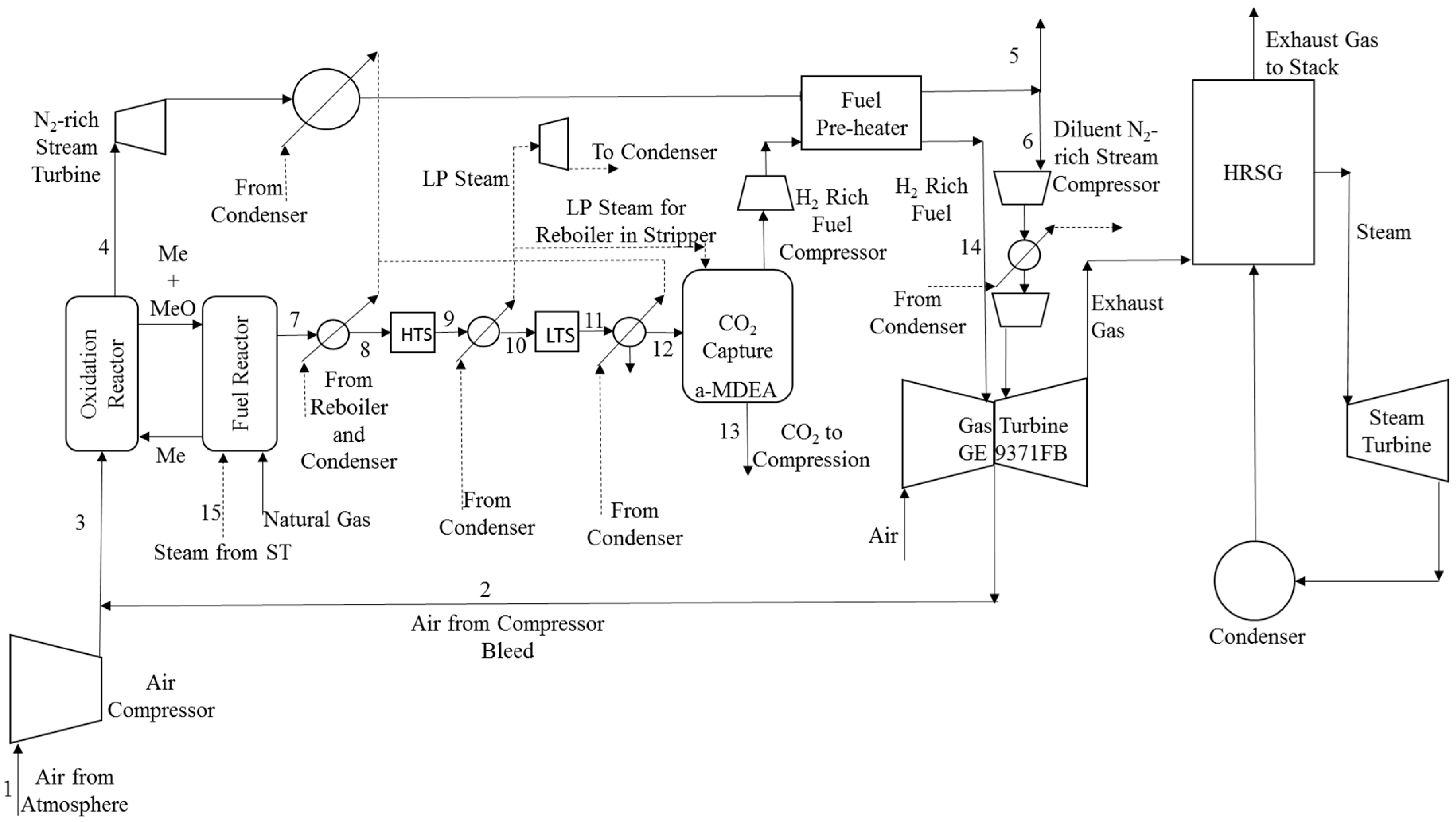
Figure 3.
Schematic of the Heat Recovery Steam Generator (HRSG) and steam turbine (ST) system.
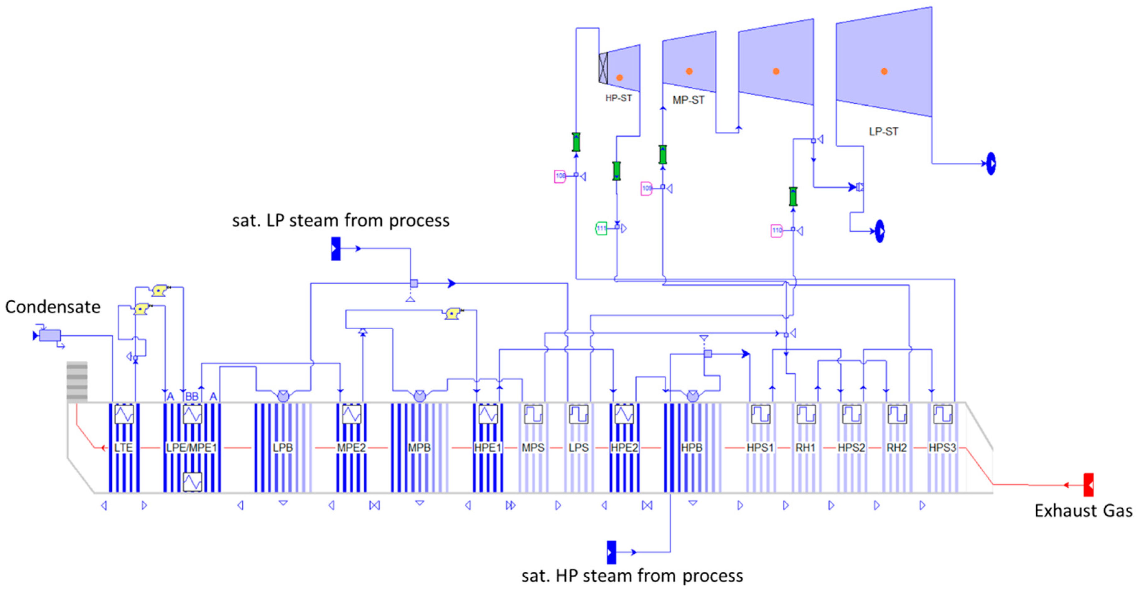
Figure 4.
Schematic of the CLR-CC process for different heat integration options.

Table 1.
Steam types in different cases for heat integration.
| Steam Type | A | B | C | D | E | F |
|---|---|---|---|---|---|---|
| Base Case | sat. LP | sat. LP | sat. LP | sat. LP | sat. LP | sat. LP |
| Case 1 | sup. HP | sat. LP | sat. LP | sup. MP | sat. LP | sat. LP |
| Case 2 | sat. HP | sat. LP | sat. LP | sup. MP | sat. LP | sat. LP |
| Case 3 | sat. HP | sat. LP | sat. LP | sat. HP | sat. LP | sat. LP |
| Case 4 | sat. HP | sat. HP | sat. LP | sat. HP | sat. HP | sup. LP |
Table 2.
Process stream data for the base case (P18).
| Stream | P (bar) | T (°C) | Flow TPH | H2O mol % | CO2 mol % | CH4 mol % | CO mol % | H2 mol % | N2 mol % | O2 mol % | Ar mol % |
|---|---|---|---|---|---|---|---|---|---|---|---|
| 1 | 1.01 | 15 | 505 | 1.01 | 0.03 | - | - | - | 77.3 | 20.74 | 0.92 |
| 2 | 18 | 416.7 | 555 | 1.01 | 0.03 | - | - | - | 77.3 | 20.74 | 0.92 |
| 3 | 18 | 416.7 | 1060 | 1.01 | 0.03 | - | - | - | 77.3 | 20.74 | 0.92 |
| 4 | 17.1 | 1199.3 | 816 | 1.22 | 0.03 | - | - | - | 97.52 | - | 1.16 |
| 5 | 1.02 | 134.8 | 261 | 1.22 | 0.03 | - | - | - | 97.52 | - | 1.16 |
| 6 | 1.02 | 134.8 | 555 | 1.22 | 0.03 | - | - | - | 97.52 | - | 1.16 |
| 7 | 16.25 | 984.5 | 575 | 31.09 | 8.31 | 0.17 | 17.87 | 42.34 | 0.22 | - | - |
| 8 | 15.60 | 400 | 575 | 31.09 | 8.31 | 0.17 | 17.87 | 42.34 | 0.22 | - | - |
| 9 | 15.13 | 503.7 | 575 | 21.54 | 17.86 | 0.17 | 8.33 | 51.89 | 0.22 | - | - |
| 10 | 14.83 | 200 | 575 | 21.54 | 17.86 | 0.17 | 8.33 | 51.89 | 0.22 | - | - |
| 11 | 14.38 | 278.4 | 575 | 14.85 | 24.55 | 0.17 | 1.64 | 58.58 | 0.22 | - | - |
| 12 | 13.82 | 50 | 479 | 0.98 | 28.54 | 0.19 | 1.90 | 68.13 | 0.25 | - | - |
| 13 | 110 | 25 | 391 | 0.27 | 99.40 | - | - | 0.32 | - | - | - |
| 14 | 13.34 | 140 | 86 | 0.60 | 1.80 | 0.27 | 2.64 | 94.34 | 0.35 | - | - |
| 15 | 18 | 283 | 166 | 100 | - | - | - | - | - | - | - |
Table 3.
Results from analysis of CLR-CC at different design pressures in chemical looping reforming (CLR).
Table 3.
Results from analysis of CLR-CC at different design pressures in chemical looping reforming (CLR).
| Pressure | Case (bar) | P5 | P10 | P15 | Base Case (P18) | P25 | P30 |
|---|---|---|---|---|---|---|---|
| Gas Turbine | %—LHV input | 30.3 | 29.4 | 28.9 | 28.5 | 28.6 | 28.7 |
| Steam Turbine | %—LHV input | 14.5 | 14.2 | 14.0 | 13.9 | 13.7 | 13.8 |
| N2-rich Stream Turbine | %—LHV input | 5.3 | 7.2 | 8.1 | 8.5 | 9.2 | 9.5 |
| Additional LP steam Turbine | %—LHV input | 2.7 | 2.8 | 3.0 | 3.1 | 3.3 | 3.4 |
| Diluent N2-rich Stream Compressor | %—LHV input | −4.8 | −4.7 | −4.7 | −4.6 | −4.5 | −4.4 |
| H2 rich fuel Compressor | %—LHV input | −3.1 | −1.9 | −1.3 | −1.0 | −0.6 | −0.4 |
| Air Compressor | %—LHV input | −1.3 | −2.1 | −2.6 | −2.9 | −3.9 | −4.5 |
| Pump for Regenerated Amine | %—LHV input | −0.1 | −0.1 | −0.1 | −0.1 | −0.2 | −0.2 |
| CO2 Compression | %—LHV input | −1.9 | −1.9 | −1.8 | −1.8 | −1.8 | −1.8 |
| Auxiliaries | %—LHV input | −1.2 | −1.2 | −1.2 | −1.2 | −1.2 | −1.2 |
| LHV of NG—Input | GW | 2.11 | 2.14 | 2.14 | 2.14 | 2.14 | 2.13 |
| Net Electrical Efficiency | % | 40.6 | 41.8 | 42.3 | 42.5 | 42.7 | 42.9 |
| CO2 Avoidance | % | 85.1 | 83.8 | 83.1 | 83.7 | 83.2 | 82.8 |
| CO2 Capture | % | 89.4 | 88.6 | 88.2 | 88.6 | 88.2 | 87.8 |
| Energy to compress captured CO2 | kWh/kg CO2 | 0.1 | 0.1 | 0.1 | 0.1 | 0.1 | 0.1 |
Table 4.
Main results for different cases of heat integration options.
| Cases | Units | Base Case | 1 | 2 | 3 | 4 |
|---|---|---|---|---|---|---|
| Gas Turbine | MW | +611 | +611 | +611 | +611 | +611 |
| Steam Turbine | MW | +298 | +452 | +403 | +403 | +415 |
| N2-rich Stream Turbine | MW | +182 | +182 | +182 | +182 | +182 |
| Additional LP steam Turbine | MW | +67 | - | - | - | - |
| Diluent N2-rich Stream Compressor | MW | −99 | −99 | −99 | −99 | −99 |
| H2 rich fuel Compressor | MW | −21 | −21 | −21 | −21 | −21 |
| Air Compressor | MW | −62 | −62 | −62 | −62 | −62 |
| Pump for Regenerated Amine | MW | −3 | −3 | −3 | −3 | −3 |
| CO2 Compressors and Pump | MW | −40 | −39 | −39 | −40 | −39 |
| Auxiliaries | MW | −25 | −27 | −23 | −22 | −25 |
| Net Electrical Output | MW | 909 | 994 | 949 | 950 | 959 |
| Mass of NG Input | TPH | 166 | 166 | 166 | 166 | 166 |
| LHV of NG—Input | MW | 2139 | 2140 | 2140 | 2139 | 2140 |
| Net Electrical Efficiency | % | 42.5 | 46.5 | 44.4 | 44.4 | 44.8 |
| CO2 Avoidance | % | 83.7 | 83.2 | 83.1 | 83.3 | 83.2 |
| CO2 Capture | % | 88.5 | 88.2 | 88.2 | 88.3 | 88.2 |
© 2018 by the authors. Licensee MDPI, Basel, Switzerland. This article is an open access article distributed under the terms and conditions of the Creative Commons Attribution (CC BY) license (http://creativecommons.org/licenses/by/4.0/).
Share and Cite
MDPI and ACS Style
Nazir, S.M.; Bolland, O.; Amini, S. Analysis of Combined Cycle Power Plants with Chemical Looping Reforming of Natural Gas and Pre-Combustion CO2 Capture. Energies 2018, 11, 147. https://doi.org/10.3390/en11010147
AMA Style
Nazir SM, Bolland O, Amini S. Analysis of Combined Cycle Power Plants with Chemical Looping Reforming of Natural Gas and Pre-Combustion CO2 Capture. Energies. 2018; 11(1):147. https://doi.org/10.3390/en11010147
Chicago/Turabian StyleNazir, Shareq Mohd, Olav Bolland, and Shahriar Amini. 2018. "Analysis of Combined Cycle Power Plants with Chemical Looping Reforming of Natural Gas and Pre-Combustion CO2 Capture" Energies 11, no. 1: 147. https://doi.org/10.3390/en11010147
Note that from the first issue of 2016, this journal uses article numbers instead of page numbers. See further details here.