1. Introduction
As the popularity of renewable energy is increased drastically, the improvement and development of advanced power interface circuits such as DC/AC or DC/AC converters are always needed in terms of the efficiency of the system. In renewable/alternative energy applications such as photovoltaic or fuel cell energy system, due to a low voltage output with a high current density, normally a boost mode DC/DC power converter is required. Recently, the ripple current generated from the fuel cells has been issued even in residential and vehicle power applications because this ripple current can propagate through the system, and such a ripple current effect may shorten the fuel cell life and cause a frequent trip due to overcurrent and even harmonics problems. The ripple current suppression is mentioned in [
1,
2,
3,
4,
5,
6,
7,
8,
9,
10,
11,
12,
13,
14,
15]. The slide mode control theory was initially carried out for variable structure systems (VSS) [
3]. Since then, due to the fact that switching frequencies of power converters has to be controlled and limited, sliding mode controller (SMC) has been difficult to apply for practical applications directly [
4,
5]. Seyed et al. [
6] proposed a sliding mode algorithm and designed a second order sliding mode model for a DC/DC buck converter for achieving the robust control and fast response especially under load and input voltage variations. The frequency is limited by a complicated algorithm. In order to expand the SMC theory on power converters, a time-optimal-based SMC method for stabilizing output voltage of buck converter under perturbations was introduced [
7]. Komurcugil [
8] proposed an adaptive terminal sliding-mode control strategy for assuring a finite time convergence of converters. To improve the dynamic response of DC-DC converter, the SMC was explicitly investigated by Tan [
9]. Compared to the SMC study on a single phase converter, this paper aims at a multiphase converter. As the switching frequency is bounded in a range, to achieve a certain performance in terms of convergences or stability, the switching frequency will be varied in various ways. Due to the nature of a single-phase converter, the ripple component will vary with the switching frequency, meaning the ripple component generated by SMC cannot be directly controlled. In a typical single-phase power converter, larger inductance or a higher switching frequency could be a solution for mitigating this ripple component, resulting in bulky volumes of the inductor or larger switching power losses. On the contrary to the single-phase power converter, a multiphase power converter with SMC can drive to generate lower harmonics contents and less switching losses [
3,
10,
11,
14,
16]. For instance, with the same input and output operation conditions, a two-phase power converter will have only one-fourth of the switching losses compared to a single-phase converter. The yielded harmonics from the multiphase power converter will have a smaller amplitude and higher frequency such that the harmonics could be easily filtered away. To generate a proper phase shift between each switching cell, a master–slave structure [
17,
18,
19] is adopted because of the simplicity in terms of self-adjusting and easy implementation instead of the ring configuration proposed in [
14,
20]. In the following sections, the description of the single-phase SMC and geometric ripple cancellation with multiple switching phase is provided in
Section 2. In
Section 3, the PSIM simulation and experimental results are provided for demonstrating the operation and validation of multiple-phase slide control mode. The conclusion is provided in
Section 4.
2. Sliding Mode Control
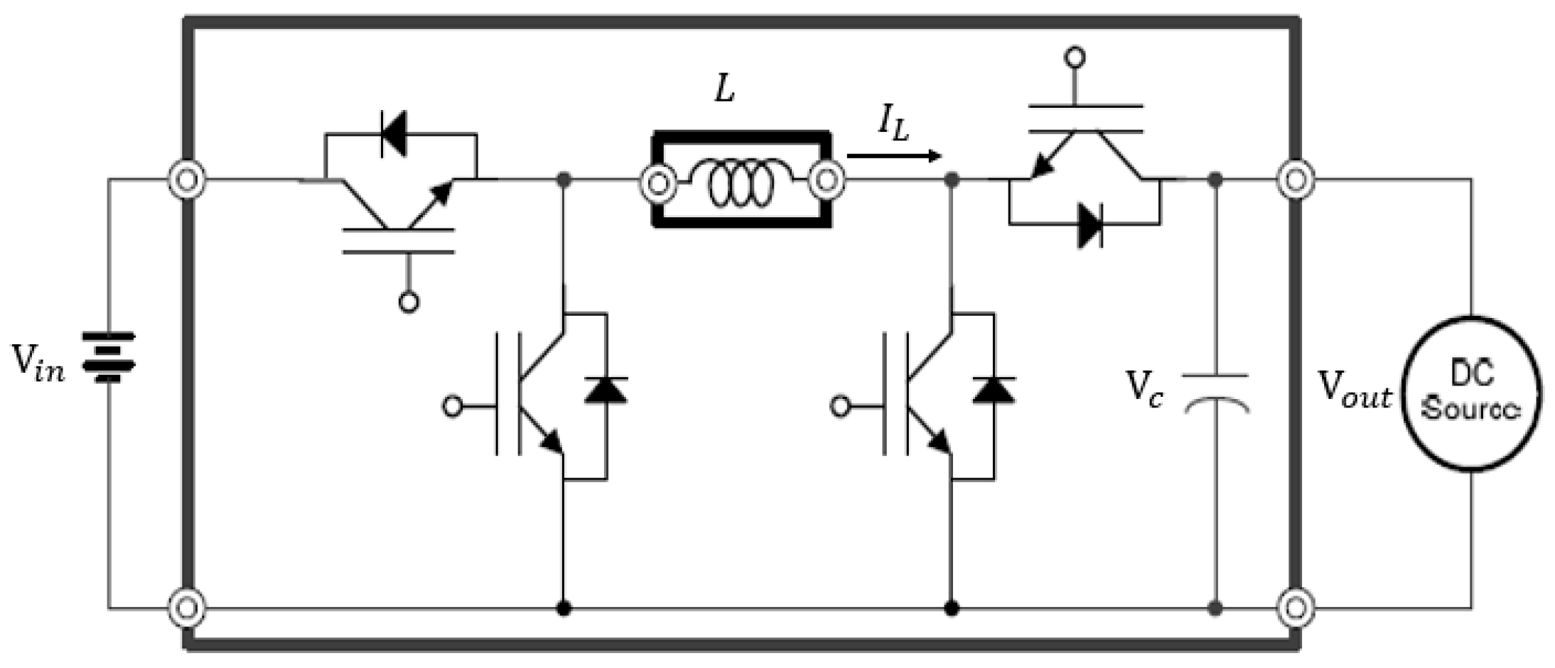
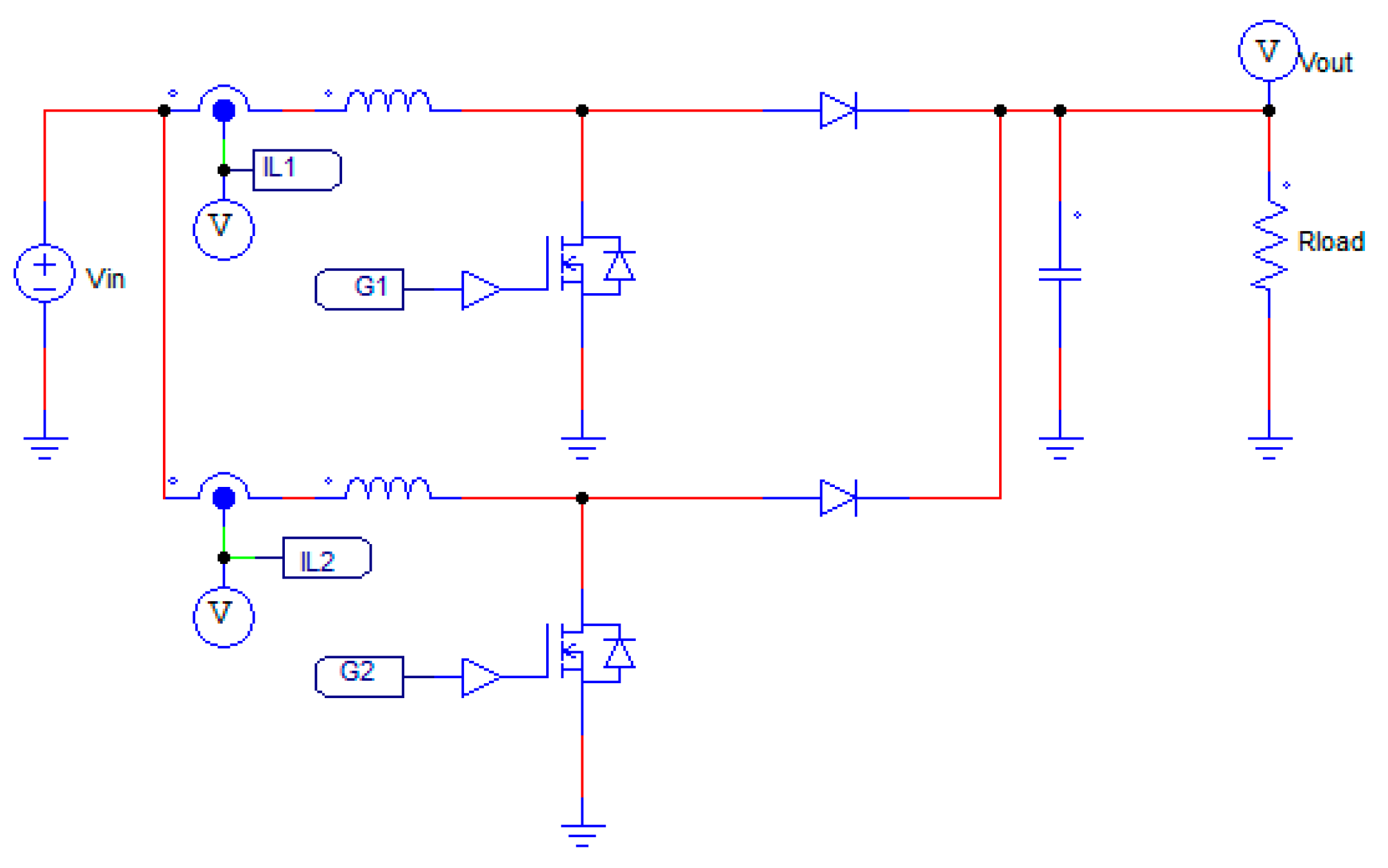
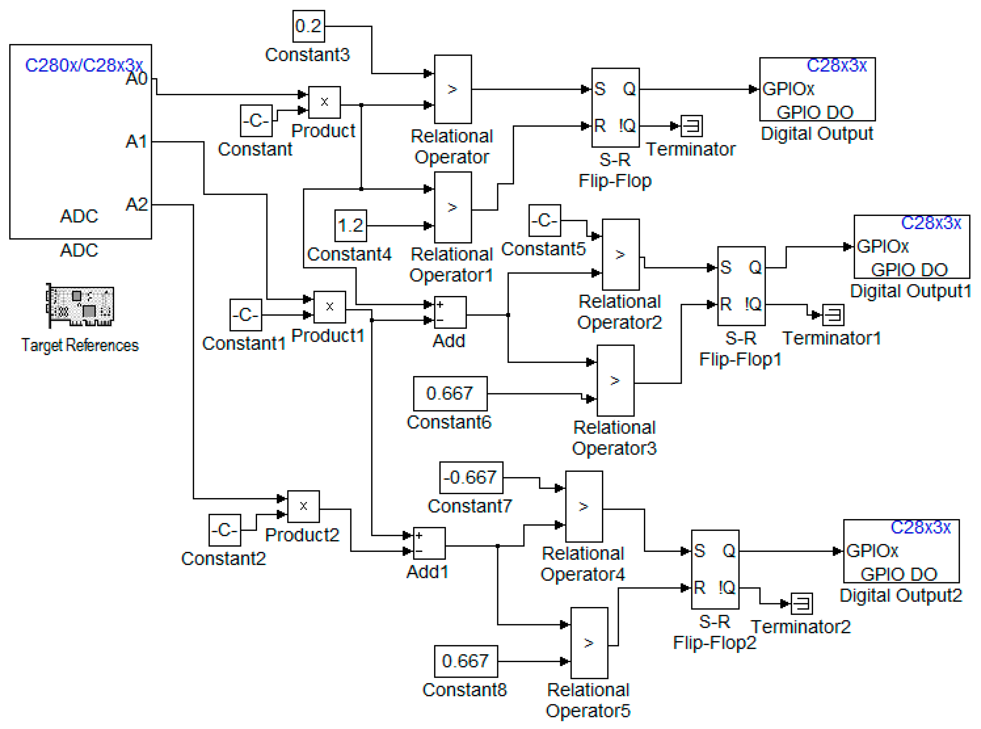
To control a DC/DC converter shown in
Figure 1 and
Figure 2, one can directly use predesigned pulse width modulation (PWM) signals with known few factors such as a load current, switching cell, acceptable ripple amplitudes, etc. It is quite simple to run a DC/DC converter under a fixed condition. In fact, the operating conditions of a practical DC-DC converter are changing under various circumstances. As a result, the ripple amplitude will be varying based on the traditional PWM control method whereas e Slide Mode Control (SMC) method can have a better advantage for this issue. By informing the control loop with the desired tolerances in advance, SMC loop can identify the switching frequency. To run a DC/DC converter using traditional PWM control method, we have to properly design a controller to avoid instability issues whenever the operating point changes with heavy control design. On the contrary, as long as the input parameters of the slide mode control loop are selected correctly, which means that those parameters can achieve Lyapunov stability in the overall operating ranges, the controller could be built easily with a minimal calculation. For example, when the circuit shown in
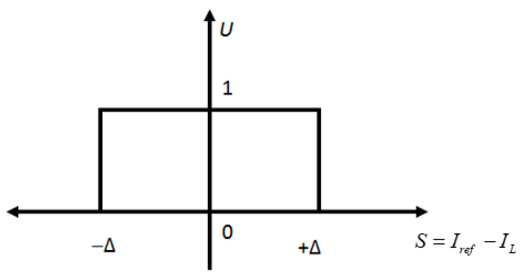
Figure 1 works as a traditional boost converter, we can design a SMC controller based on Equations (1)–(3). In this case, the input inductor current will be selected as the control input. As long as Equation (1) is always greater than zero, and Equation (2) is always less than zero, the SMC DC/DC boost converter will be always stable. To assist comprehensive understanding of the SMC, a single-phase hysteresis loop is shown in
Figure 3.
where
V is Lyapunov candidate,
s is the switching surface,
Iref is the reference current and
IL is the Inductor current.
where
Vin is the input voltage,
Vc is the capacitor voltage, and
u is the control input.
(i) Single-Phase SMC
In general, a system could be written as the following form:
where
u is the system input and has a definition of –M sign().
is the selected slide manifold of the system.
M is the positive constant.
If the sliding surface
is linearly related to the system state,
x, then the derivative of the system could be drawn as:
where
Let’s use A(x) for denoting , and use B(x) for denoting .
Assume that there are no additional unmodeled dynamics, the width of the chattering of this one-dimensional system could be presented by:
where
To understand the correlation between the widths of the chattering, dynamic the system trajectories, there should be additional information:
Also, if the system is assumed to be stable,
B(
x)
M should be greater than
A(
x) because if the system is unstable during both turn-on and turn-off periods, then the system trajectory will be definitely deviated from the slide surface, which is totally undesirable. Therefore, the
could be further written as:
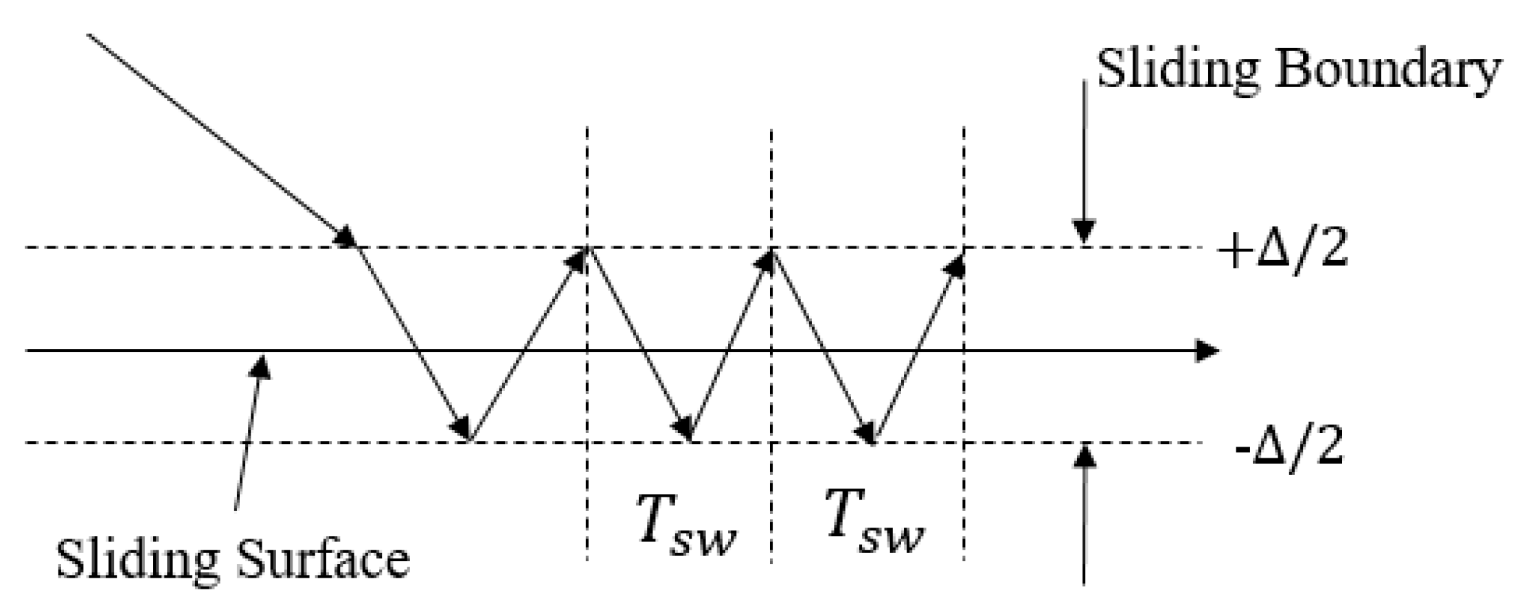
In a power converter system, the parameters of passive components such as inductor and capacitor will be definitely invariant during the operation. It means that as long as the input and output parameters (currents and voltages) of the power converter and the switching period are kept constant while operating, the sliding boundary would be inherently limited, which is shown in
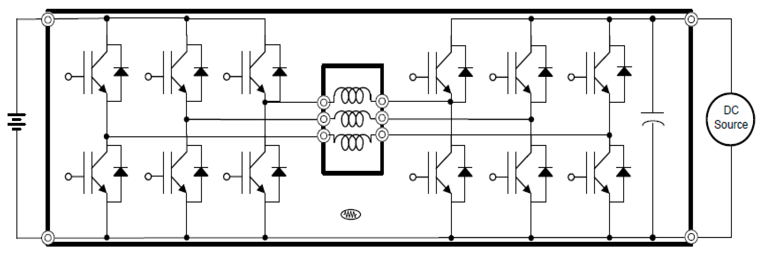
Figure 4. Changes in input parameters or output parameters potentially introduce an increase in the sliding boundary. If so, in order to diminish the chattering amplitude in a single-phase power converter, the switching frequency of the power converter has to be increased. As mentioned above, increasing switching frequency may not be beneficial for the system efficiency. Also, the width of the hysteresis loop determines the amplitude of the current chattering so that the single-phase SMC control still shares the same issue being faced with traditional PWM control. However, the multiphase converter shown in
Figure 5 can be a reasonable solution if the phase error between each phase could be maintained.
(ii) Multiple-Phase SMC
On the contrary, by using a multiple-phase power converter, the chattering issue could be dramatically mitigated, while the difficulty of the SMC design of a multiplephase power converter will get higher. It may be easy to choose an appropriate switching frequency and phase error for meeting the chattering tolerance, as long as the system parameters such as voltage, current, inductance, and capacitance are known in advance. Therefore, the multiphase SMC scheme is supposed to be handling the various system dynamics while suppressing the chattering.
There are two questions to be answered: (1) How to build the intercorrelated phase error; (2) how we could dynamically manipulate the switching frequency if the system status changes.
(1) Build intercorrelated phase error:
Based on the slide mode control scheme, the objectives in this section are to guarantee the desired phase error while making sure each slide surface will eventually converge to zero.
Given the Lyapunov theories, as long as the sliding mode condition
is guaranteed, each switching phase of the system could be definitely stable. Also, two consecutive slide surfaces can have an intercorrelation as follows:
where
k = 1, 2, 3, …
According to the
Figure 6, the Lyapunov stability on each slide surface is assured, and also every phase converges to zero eventually, which is desirable on a multiphase SMC system.
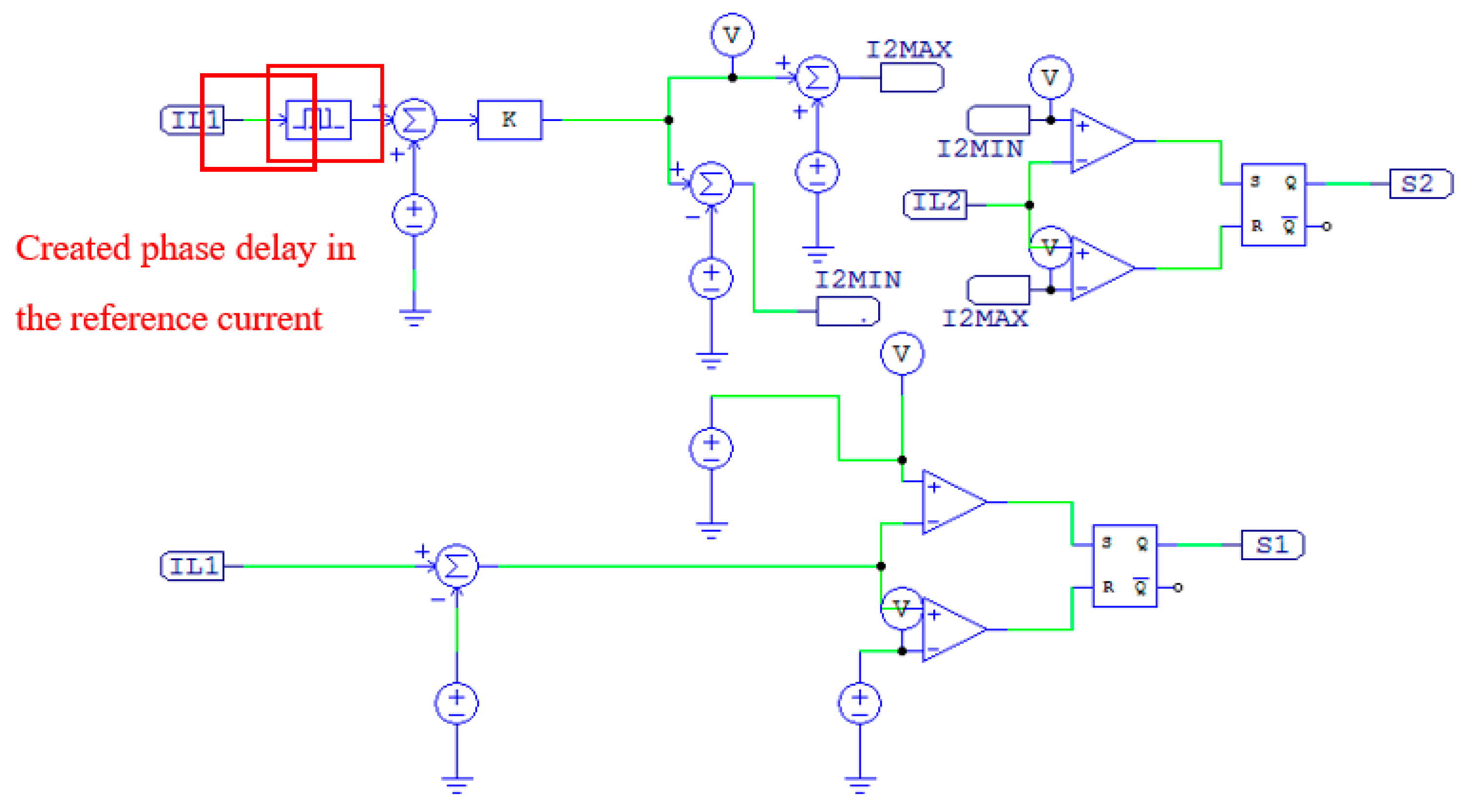
(2) Propose a master-slave slide mode control scheme:
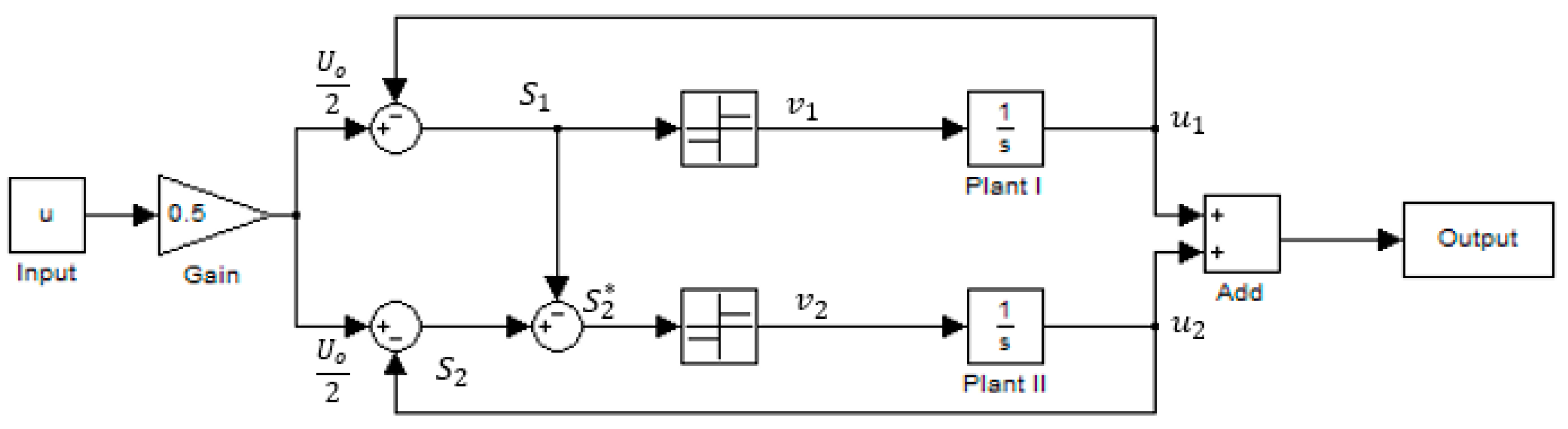
To achieve the desired phase error, a master–slave slide mode control scheme is proposed. The methodology is to have the first switching phase chattering around its desired slide surface, and then refer this trajectory to the second switching phase. And then refer the trajectory of the second sliding surface to the third switching phase. A two-phase master slide mode system can be seen in
Figure 7.
Given
Figure 7, the following equations can be considered:
where
s1 and
s2 are switching surfaces for each phase.
M is the switching gain. (In the case shown in
Figure 7,
M equals 1),
is the circuit nature. (In the case shown in
Figure 7,
equals 0).
Because both
and
have different dynamics,
and
will definitely have different hysteresis. However,
and
are supposed to have the same hysteresis. Before further the discussing of the multiphase control, the following information could be derived.
In general, the passive components in a power electronic system will be fixed in terms of parameters like inductance, capacitance, and resistance. Therefore,
M is to be constant. Assume that the multiphase SMC system works properly and the first slide surface can provide a calculated switching frequency as long as the hysteresis width of the chattering could be given. Then the hysteresis of
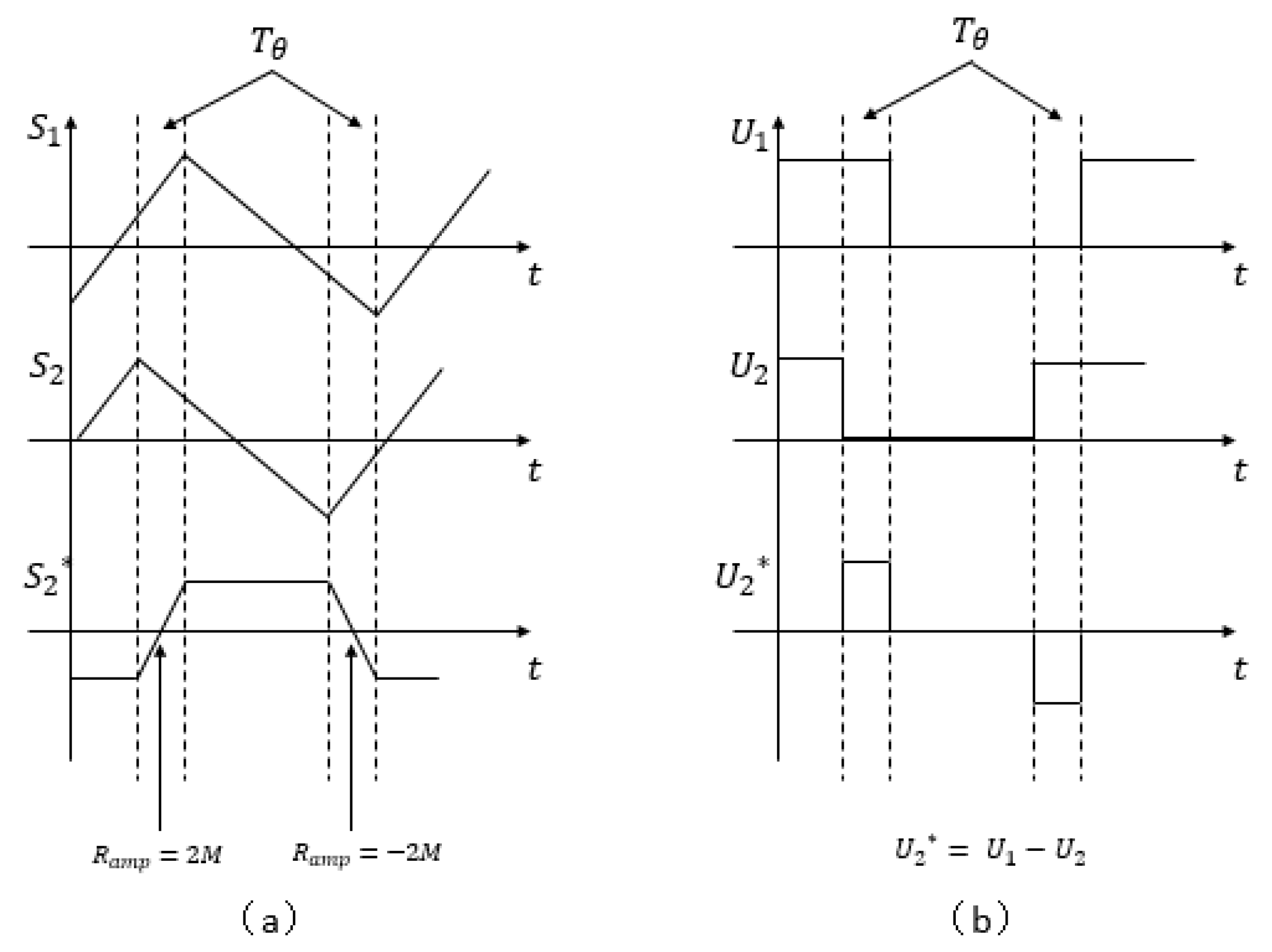
could be further derived with the calculated switching frequency, and a desired phase error. Based on the nature of the ON/OFF switching signal and above Equation (10), the slope of the
is supposed to be 2
M during the phase delay (assume that
can be 1, and
can be 0, and vice versa). So the width of the hysteresis
is:
where
is the desired phase delay.
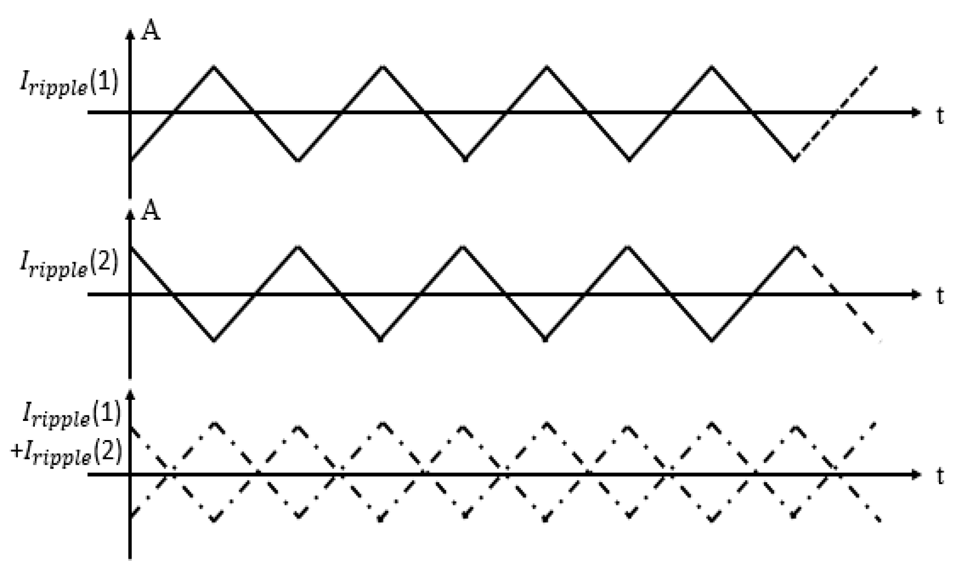
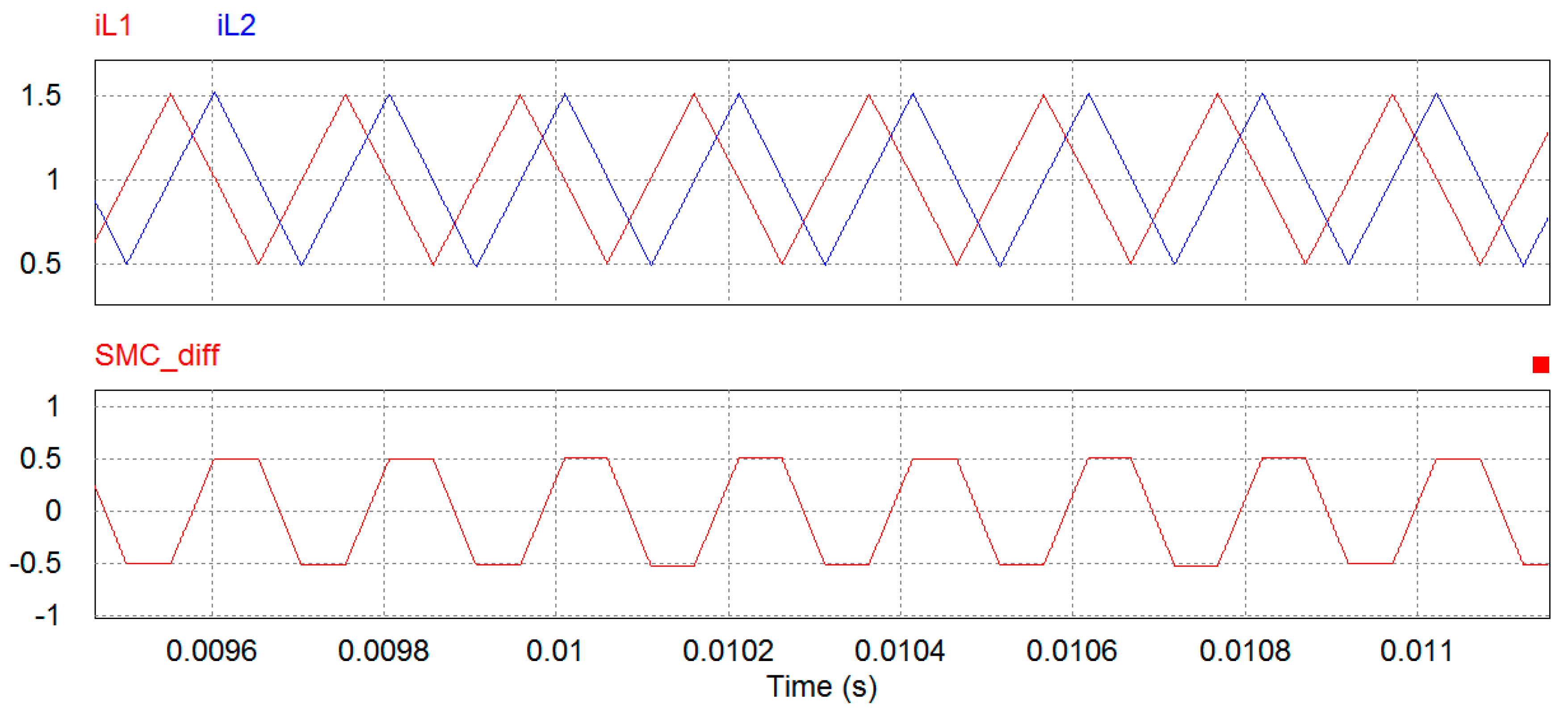
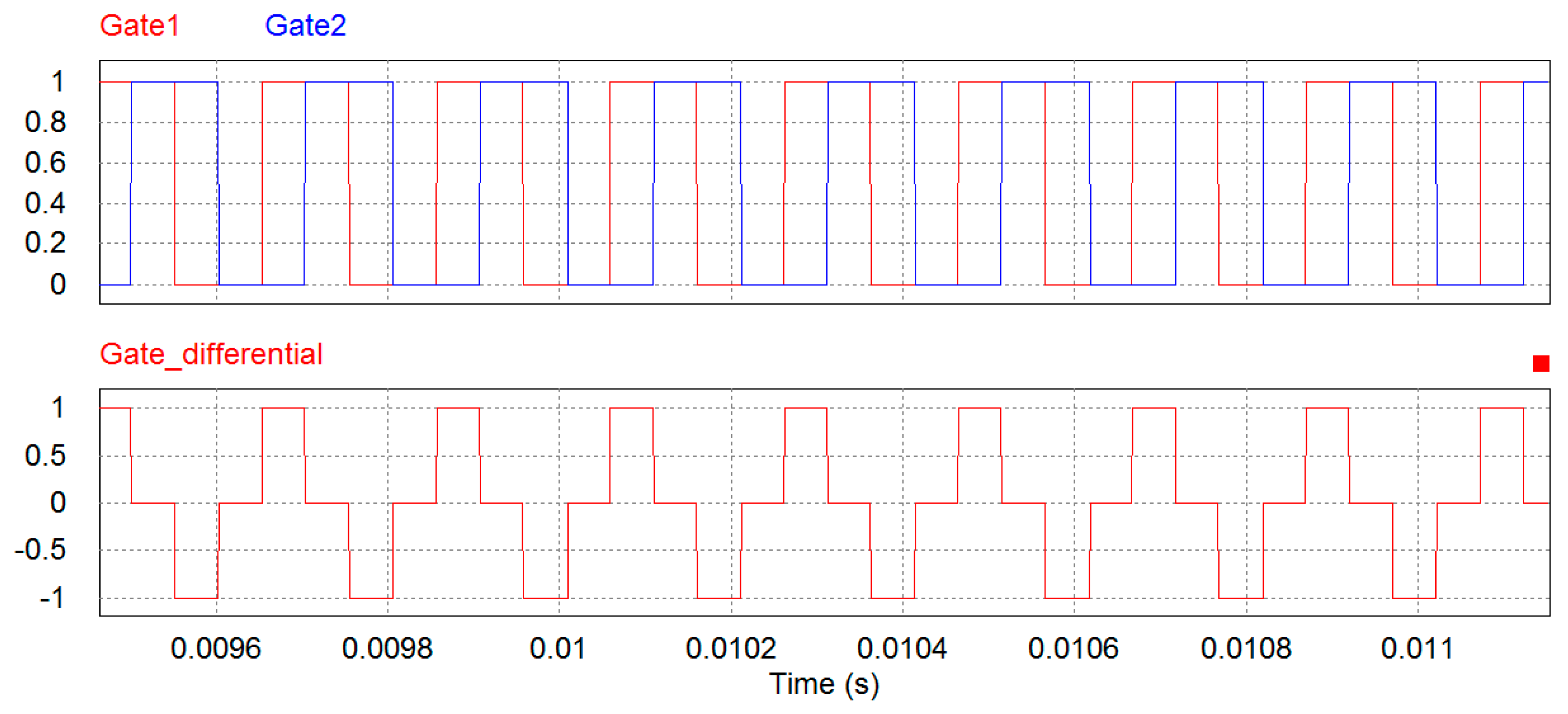
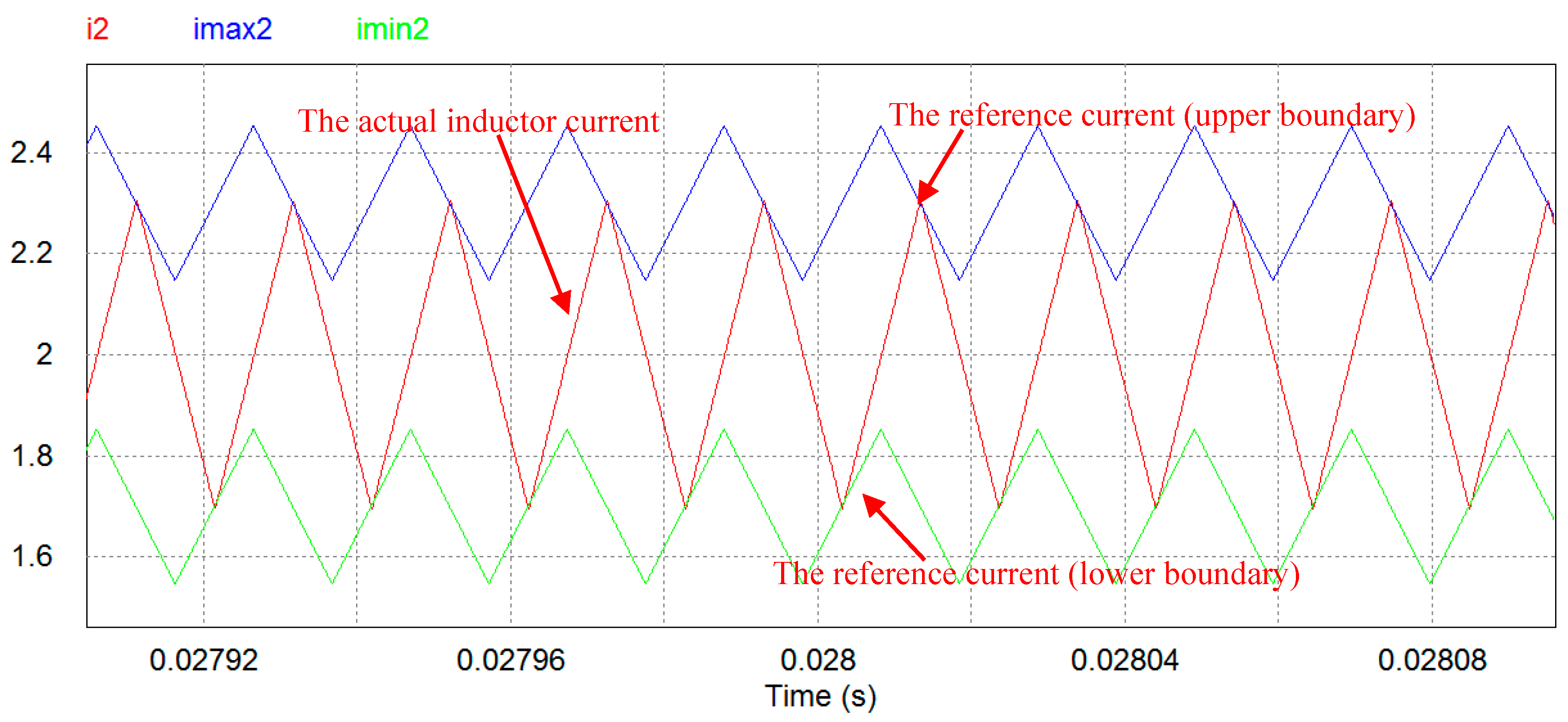
Figure 8a illustrates the consequence of having a phase delay between two switching phases.
directly presents a hysteresis loop between two switching phases. Ideally, if parameters of two switching phases,
and
are identical, then the ramps of the rising edge and falling edge of
are supposed to be also identical in terms of absolute values. In
Figure 8b,
represents the difference between inputs of two slide surfaces
and
. The polarity of
accordingly indicates the rising edge and falling edge of
.


