Article

A New Tree-Type Fracturing Method for Stimulating Coal Seam Gas Reservoirs

1
State Key Laboratory of Coal Mine Disaster Dynamics and Control, Chongqing University, Chongqing 400044, China
2
National & Local Joint Engineering Laboratory of Gas Drainage in Complex Coal Seam, Chongqing University, Chongqing 400044, China
*
Authors to whom correspondence should be addressed.
Energies 2017, 10(9), 1388; https://doi.org/10.3390/en10091388
Submission received: 20 August 2017 / Revised: 3 September 2017 / Accepted: 8 September 2017 / Published: 13 September 2017

Abstract

:
Hydraulic fracturing is used widely to stimulate coalbed methane production in coal mines. However, some factors associated with conventional hydraulic fracturing, such as the simple morphology of the fractures it generates and inhomogeneous stress relief, limit its scope of application in coal mines. These problems mean that gas extraction efficiency is low. Conventional fracturing may leave hidden pockets of gas, which will be safety hazards for subsequent coal mining operations. Based on a new drilling technique applicable to drilling boreholes in coal seams, this paper proposes a tree-type fracturing technique for stimulating reservoir volumes. Tree-type fracturing simulation experiments using a large-scale triaxial testing apparatus were conducted in the laboratory. In contrast to the single hole drilled for conventional hydraulic fracturing, the tree-type sub-boreholes induce radial and tangential fractures that form complex fracture networks. These fracture networks can eliminate the “blank area” that may host dangerous gas pockets. Gas seepage in tree-type fractures was analyzed, and gas seepage tests after tree-type fracturing showed that permeability was greatly enhanced. The equipment developed for tree-type fracturing was tested in the Fengchun underground coal mine in China. After implementing tree-type fracturing, the gas extraction rate was around 2.3 times greater than that for traditional fracturing, and the extraction rate remained high for a long time during a 30-day test. This shortened the gas drainage time and improved gas extraction efficiency.

1. Introduction

Coalbed methane (CBM), a source of clean energy, can be exploited either through boreholes drilled from the surface or from the workings of underground coal mines. Chinese CBM recovery mainly depends on underground coal mining. In 2015, underground CBM production was 13.6 billion cubic meters, accounting for 76% of the total CBM recovered in China [1]. The CBM reservoirs in Chinese mines are characterized by low saturation, low permeability, low reservoir pressure, and relatively high metamorphic grade [2]. The production of CBM from this kind of reservoir is a worldwide problem, and it is also the main difficulty in the development of Chinese CBM extraction. Moreover, the geology of CBM reservoirs in China in particular means that more than 70% of China’s coal fields are not suitable for development of large-scale ground CBM production [3]. These geological conditions make it necessary for underground mines in China to exploit coal and CBM simultaneously.
A number of different methods have been employed to improve the efficiency of underground CBM extraction. These methods include deep-hole pre-split blasting, hydraulic slotting, hydraulic flushing, and hydraulic fracturing [4,5,6,7]. Hydraulic fracturing (HF) has been used widely because it reduces stress in a large volume of the reservoir and it is simple [8]. However, problems like crack propagation toward the coal seam roof or floor, uneven crack propagation, and rapid crack closure commonly occur during HF, leading to poor fracture conductivity and low CBM extraction efficiency [9]. More importantly, conventional HF only generates a single main fracture, and “blank areas” (areas from which the gas cannot be drained) on both sides of the fracture leave gas-rich regions. These hidden trouble spots are a safety hazard for subsequent coal mining and may lead to coal and gas outbursts. Therefore, CBM exploitation in underground coal mines requires a new method for HF to stimulate the reservoir volume that will “break up” the reservoir to develop the largest contact area possible between fracture surfaces and reservoir matrix. Such action would promote large-scale and balanced stimulation of CBM production.
Scientists and engineers both in China and abroad have attempted to develop new fracturing techniques for underground CBM extraction. To improve the effective range of HF, Zhai et al. [10] combined deep-hole controlled blasting with HF. However, this method had some inherent defects, because deep-hole blasting cannot be used in areas with high gas contents [11]. Some studies applied HF in slots formed by high pressure water jet (hydraulic slotting). The purpose of this method was to use the slots to control the direction in which the hydraulic fractures extended [12,13]. However, this method has some limitations such as: the radius of the hydraulic slot is short (<2.5 m), the scope for pressure relief is limited, and the fractures beyond the relief area are still in the form of a single main fracture. This last limitation means that there are still “blank areas” on both sides of the main fracture, and for this reason this method is unable to produce a large stimulated volume in the reservoir [14,15]. As mining depths increase, the deep coal seam shows the features of high ground stress difference and frequent changes of tectonic stress [16]. For these reasons, it is difficult to control the initiation and propagation directions of the main fractures and to induce secondary fractures. Combined with the inherent lower permeability of deep coal seams, permeability improvement becomes more difficult and efficient CBM extraction is faced with additional problems.
In this paper, based on the traditional underground HF technique, a new tree-type fracturing technique is proposed. A self-propelled bit is used to drill tree-shaped boreholes parallel to coal bedding from a cross-layer main borehole. Hydraulic fracturing is then performed via main borehole and these bedding-parallel tree-type boreholes. The new methods and equipment needed for this fracturing technique are introduced in this paper. This fracturing technique generates reticular fractures. The mechanism of fracture formation and the principle of reservoir permeability improvement are analyzed theoretically. In addition, simulation experiments were conducted in the laboratory to investigate how the reticular fractures propagate in the coal seams and their effect on the stimulated CBM volume. Finally, a field test of this method was made to provide an actual application for efficient gas extraction from a coal seam.

2. Synopsis of the New Tree-Type Fracturing Technology

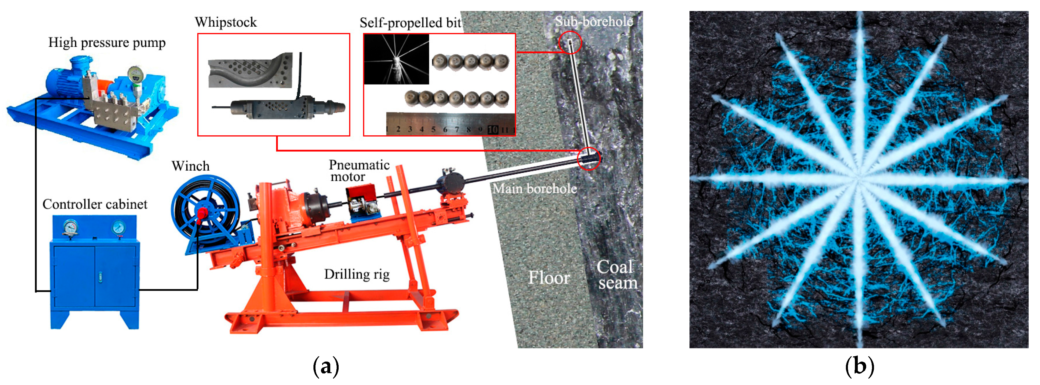
2.1. Tree-Type Fracturing Method

The equipment needed for tree-type fracturing in underground coal mines is shown in Figure 1a. First, a cross-layer borehole is drilled from a floor roadway into the coal seam. This borehole is called the main borehole. Second, a whipstock is installed at the end of the main borehole and the whipstock’s outlet aimed parallel to the bedding in the coal seam. Next, a self-propelled bit is introduced into the whipstock and negotiates the turn to go into the coal seam. This self-propelled bit is designed [17], so that it can break the coal in the seam and, using high-pressure water jets, drill a sub-borehole the length of which can be as much as 10 m. The bit moves forward under its own self-propelling force generated by backwards-facing water jets. By changing the position and orientation of the whipstock, a number of sub-boreholes can be drilled in the coal seam forming the tree-type fracturing net. When all drilling has been completed, the main borehole is cased and sealed and hydraulic fracturing is started. Initiated along the lengths of the tree-type sub-boreholes, hydraulic fractures propagate to form a tree-type net of fractures in the coal seam, as shown in Figure 1b.
Tree-type drilling and fracturing can effectively induce an extensive fracture network to homogeneously improve permeability in a coal seam and increase the efficiency of CBM extraction. Compared with traditional HF, the new method has a number of advantages including: (1) the volume of coal fractured from single-hole is larger and thus the volume with improved permeability is also larger; (2) fracturing is more homogeneous and “blank area” are eliminated; (3) the fluid pressure needed to initiate and propagate fractures is reduced and this reduces damage to the roof and floor of the coal seam; (4) the concentration of CBM in the gas extracted is improved; and (5) the equipment is small in size and well suited for use in underground coal mines.

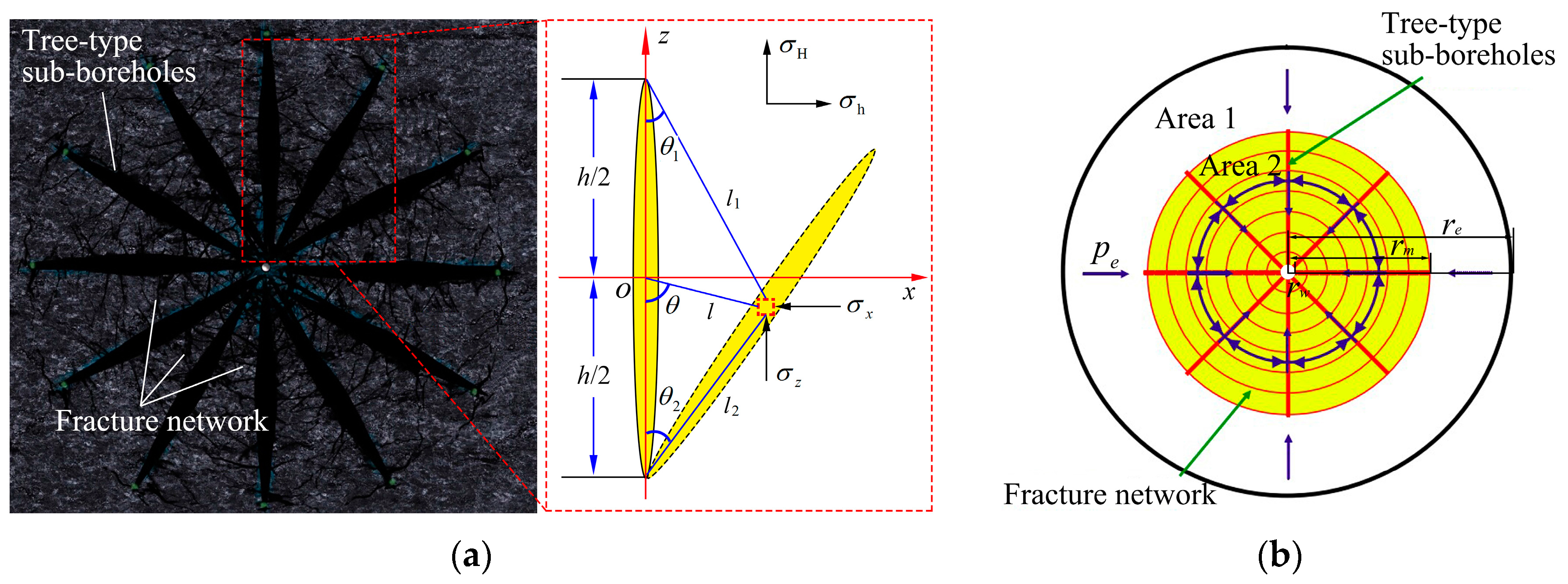
2.2. Tree-Type Sub-Borehole Fracture Theory

Controlling fracture propagation under different principal stress directions and inducing complex fractures between tree-type sub-boreholes is the key to success for tree-type fracturing. Assuming the distances between sub-boreholes are equal and taking two adjacent sub-boreholes as examples, based on the theory of elastic mechanics, the analysis of the stress induced by hydraulic fractures is a plane strain problem. According to a plane strain model, the geometry of the two-dimensional stress field can be obtained (Figure 2a). The difference in induced stress at any point can be expressed by Equation (1) [18,19]:
Δ σ h Δ σ H = p ( 2 ν 1 ) [ l ( l 1 l 2 ) 1 / 2 cos ( θ 1 2 θ 1 1 2 θ 2 ) 1 ] p l c ( c 2 l 1 l 2 ) 3 / 2 sin θ sin [ 3 2 ( θ 1 + θ 2 ) ]
where Δσh and ΔσH are, respectively, the induced stresses in the directions of minimum and maximum horizontal principal stress in MPa, p is the fluid pressure in the sub-borehole in MPa, υ is Poisson’s ratio, l, l1, and l2 are, respectively, the distances of any point from the sub-borehole center and from the two ends of sub-borehole in meters, θ is the angle between the sub-borehole direction and the line from any point to the sub-borehole center in °, θ1 and θ2 are, respectively, the angles between the axis of the sub-borehole and the line from any point to the two ends of the sub-borehole in °, and c = h/2 with h being the sub-borehole length in meters.
Assuming that the main-borehole is normal to the principal stress direction, the sub-boreholes are of equal length, and the net pressures in the holes are the same, the induced stress on adjacent sub-borehole walls can be obtained by induced stress superposition:
Δ σ = Δ σ 1 + Δ σ 2
Δ σ 1 = p ( 1 2 ν ) [ 1 l ( l 2 + c 2 ) 1 / 2 ] + p c 2 l ( l 2 + c 2 ) 3 / 2
Δ σ 2 = p ( 1 2 ν ) { 1 | ( l d ) | [ ( l d ) 2 + c 2 ] 1 / 2 } + p c 2 | ( l d ) | [ ( l d ) 2 + c 2 ] 3 / 2
where Δσ1 and Δσ2 are, respectively, the induced stress difference between two adjacent sub-boreholes in MPa and d is the sub-borehole spacing in meters.
At the end of sub-borehole, l reaches its maximum value, and the induced stress is the smallest there. That the reduced stress there is greater than ground stress difference is regarded as the fracture propagation condition. The expressions of l and d is:
{ l = 2 h sin θ 2 2 d = h sin θ 2
Substituting Equations (3)–(5) into Equation (2), the value for the induced stress difference can be obtained. According to elastic mechanics and rock failure criteria, the hydraulic fracture failure surface is always perpendicular to the direction of minimum horizontal principal stress. If the fracture is to change direction, the induced stress difference must be larger than the initial horizontal principal stress difference in the reservoir [20,21].

2.3. Gas Seepage after Tree-Type Fracturing

The traditional theoretical model for hydraulic fracturing has the hydraulic fracture as a symmetric double-wing fracture with the main fractures playing the leading role in improving the reservoir’s seepage capability [22]. Using this model, gas must seep through a relatively thick interval of coal matrix to reach a fracture. Because a complicated fracture network is formed during tree-type fracturing, the gas has only a short distance from a fracture in any direction and must seep through much thinner intervals of coal matrix to reach fractures. This is illustrated diagrammatically in Figure 2b. The yellow area (Area 2) represents the stimulated volume and the white area (Area 1) represents the area not affected by tree-type fracturing but in the seepage area. The thick red lines portray the sub-boreholes and the red circles portray the fracture network composed of hydraulic fractures and micro fractures in the coal. The blue arrows illustrate gas flow directions. Gas first flows to the fractures and then to the main borehole via the fracture network. Because the seepage distances are short, the pressure needed to drive the gas to the fractures is greatly reduced, thus achieving the effect of stimulating the reservoir.
Due to the complexity and uncertainty about the location of fractures in the stimulated yellow area (Area 2) related to the distance of any point from main borehole center r, a fractal body is used to characterize this area [23,24]. At the locations close to the main borehole center, the sub-boreholes spacing is small, the fracture distributions are dense, and the permeability of this region is big. On the contrary, the farther locations have the smaller fracture intensity and the smaller permeability. Therefore, it can be assumed that the permeability of the stimulated area is a power exponent function related to r. The fractal assumption for the permeability of the stimulated area is:
k 2 = k 1 ( r m r ) β ,   r w r r m
where k1 is the permeability of Area 1, k2 is the permeability of Area 2, and β is the dimension of the fractal area (Area 2), 0 < β < 1, and it depicts the fracture morphology and the connectivity of the fracture network. The other parameters in the model are reservoir thickness h, the radius of the main borehole rw, the viscosity of CBM μ, the initial pressure gradient G, the equivalent reservoir radius re, the reservoir boundary pressure pe and the tree-type fracturing radius rm.
For two-dimensional radial stable seepage, the pressure distribution in stimulated Area 2 and external seepage Area 1 can be established based on continuity and motion equations. By solving these control equations simultaneous, the pressure distribution formula for Area 1 can be expressed according to the coupling interface pressures being equal [25]:
p ( r ) = p e G ( r e r ) c 2 ln ( r e / r ) ,   r m r r e
and then Equation (8) can be obtained:
c 2 = p e G ( r e r m ) + r m G ln ( r e r m ) r m β r w r m 1 r ( 1 β ) d r + ln ( r e / r m )
Combined with the non-Darcy’s law [26], the capacity formula calculated by using the parameters from Area 1 is:
Q = 2 π k 1 r h μ ( d p d r G )
Substituting Equations (7) and (8) into Equation (9), the gas extraction flow for reservoirs stimulated by tree-type fracturing can be expressed as:
Q = 2 π k 1 h μ ( p e G ( r e r m ) + r m G ln ( r e r m ) r m β r w r m 1 r ( 1 β ) d r + ln ( r e / r m ) r m G )
The model derived above shows that the main parameters affecting gas extraction after implementation of tree-type fracturing are the fractal coefficient β and the fracturing radius rm. Fractal coefficient β is positive and represents the area’s permeability improvement. A larger β value indicates that the stimulation level for the reservoir is higher, the connectivity of the induced fracture is better, and the gas extraction flow is greater. For a given fractal coefficient, the larger the fracturing radius rm, the greater the gas extraction flow. The relationship between rm and extraction flow is approximately linear. When the gas pressure in the coal seam is higher, the fracturing radius will have a greater effect on the gas extraction flow.

3. Tree-Type Fracturing Laboratory Experiments

The key to successful tree-type fracturing is to induce interconnected fractures between each sub-borehole. In order to verify the feasibility of this fracturing method, tree-type fracturing simulation experiments under in situ ground stress and pore gas pressure conditions were conducted in the laboratory. After fracturing, fracture morphology and gas seepage were investigated to compare the effect of gas production improvements under different experimental conditions.

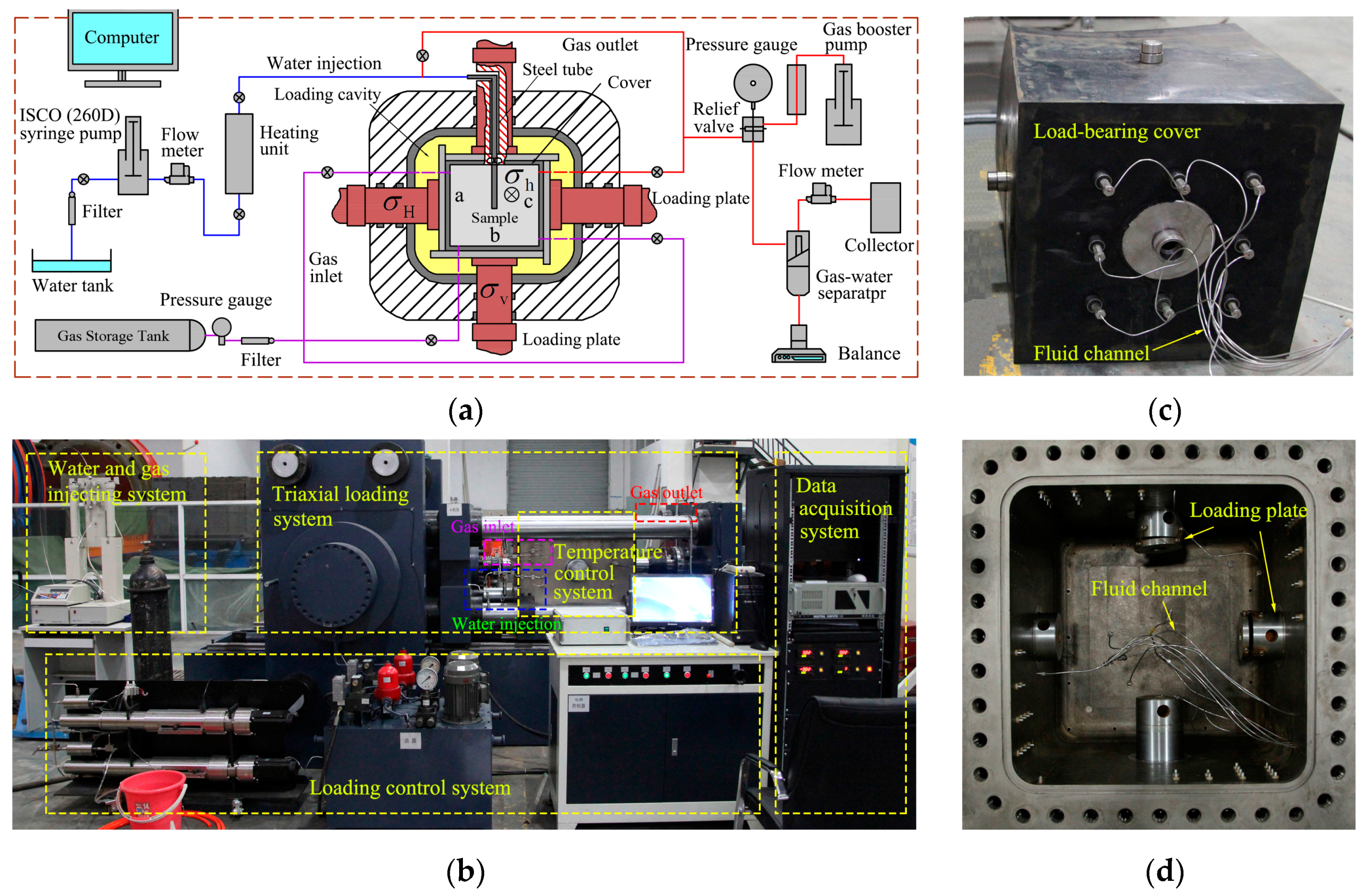
3.1. Experimental Apparatus

All experiments were carried out using a large-scale true-triaxial hydraulic fracturing test apparatus. The apparatus is shown in Figure 3a,b. It was specifically designed to be able to simulate in situ ground stresses and pore pressures in order to carry out HF and gas seepage experiments. The apparatus is composed of five main subsystems, namely the triaxial loading system, a load control system, water and gas injection systems, a temperature control system, and a real-time data acquisition system. An ISCO-260D syringe pump (Teledyne ISCO, Lincoln, NE, USA) with a maximum pressure of 51.7 MPa and a maximum flow of 107 mL/min is used for water injection. The triaxial loading and control system can apply a confining pressure of 0–25 MPa. In the vertical direction, the loading stress is equal to the confining pressure. In the axial and lateral directions, four independent mechanical loads can be imposed on the sample via electro-hydraulic servo pumps. Mechanical loading stresses can range from 0 to 35 MPa. Therefore, the stresses on the sample from the axial and lateral directions are equal to the mechanical loading stress plus the confining pressure. The accuracy of the stress control is ±1%. The oil in the confining pressure cavity is temperature-controlled and can maintain sample temperatures ranging from 20 to 100 °C. Test samples are sealed with a load-bearing cover on which there are gas inlets and outlets for gas seepage. Combined, these features mean the fracturing apparatus is capable of simulating HF under true-triaxial stress, pore pressure, and temperature conditions. It can also be used to conduct gas seepage experiments on reconstituted or fractured samples to monitor both the connectivity of hydraulic fractures and any improvements in permeability. During the experiments, the confining pressure, axial and lateral stresses, injection pressure, temperature, and strain were monitored and recorded by the real-time data acquisition system.
It is very difficult to collect and test intact coal samples for fracturing. In addition, original fractures and beddings in natural coal interfere with fracture initiation and propagation and make it difficult to observe the morphology of induced fractures. The aim of the experiment is to verify the theoretical results of fracture morphology. The homogeneous sandstone is close to theoretical assumptions and suitable for confirmatory experiment. Therefore, the fracturing experiments for this work were performed on relatively homogeneous sandstone. All samples were taken from the same large sandstone mass. The sandstone samples were cubes, with an edge of 300 mm, cut from larger blocks. A hole 15 mm in diameter and 165 mm in length was drilled at the center of each cube to simulate the main borehole that would be used for tree-type fracturing. At the bottom of the main borehole, several stimulated sub-boreholes 8 mm in diameter and 60 mm long were made with an abrasive water jet. Of course, these simulated sub-boreholes were all perpendicular to the main borehole. A high-strength AB glue was used to seal the walls of the upper portion of the main borehole making the sealed portion of the main hole 135 mm in length and leaving an open hole length of 30 mm.

3.2. Experimental Procedures

Experiments to simulate both conventional HF and tree-type fracturing under different conditions were conducted. At CBM production sites in most coal mines in China, the vertical stress on the coal seam is in most cases larger than the horizontal stresses [27]. In order to investigate the influence of horizontal stress difference on fracture morphology, the vertical stress for the experiments was set at 15 MPa, the maximum horizontal principal stress was 12 MPa, and the minimum horizontal principal stresses were 6, 7 and 8 MPa. Owing to sample size limitations, the sub-borehole length was kept constant, but in order to investigate the effect of increasing the number of sub-boreholes on fracture morphology, three, four and six sub-boreholes were tested in different experiments. The water injection flow rate was kept at 20 mL/min for all samples. The conditions under which the experiments were run are shown in Table 1.
The experimental procedures are described below.
(1)
The sample carrier was sealed with a load-bearing cover by using adhesive (Figure 3c) and then placed into the triaxial loading cavity and fixed by four mechanical loading plates (Figure 3d). The gas inlet and outlet pipes and the water injection pipe were then connected to the cover. Screens were inserted to make sure the sample was not in direct contact with the cover to ensure that the sample had full contact with seepage gas. The loading cavity was then closed and sealed.
(2)
Hydraulic oil was pumped into the loading cavity until the confining pressure reached the minimum horizontal principal stress σh. Then the axial and lateral stresses were loaded to vertical principal stress σv and the maximum horizontal principal stress σH by the servo pumps at a rate of 2 MPa/min. Next, but before fracturing was initiated, gas was injected into the sample to test sample permeability and to simulate pore pressure. Methane was used as the pore gas during testing. Gas was injected from the plane marked as “a” in Figure 3a and ejected from plane “c”. The injection pressure was 2.5 MPa [28]. When the flow of ejected gas was stable, the gas flow was used to calculate permeability [29,30]. The permeability experiments on Φ50 × 100 mm sandstone specimens taken from different directions showed that the sandstone has isotropic properties, so the permeability at a single direction can represent the permeability of sandstone [31].
(3)
After connecting the syringe pump to the simulated main borehole in the sample (by a steel tube), the real-time data acquisition system was started. The two pump plungers were filled with distilled water and then the pump was started to inject high-pressure water at the specified flow rate of 20 mL/min. The injection system pressurized until a rapid pressure drop, which indicated that the sample had fractured. The pump was shut off after the sample was fractured completely.
(4)
After fracturing, the water was drained and the gas injection system was started to conduct the gas seepage tests. Gas was injected from planes a, b and c, shown in Figure 3a, with the simulated main borehole serving as a gas outlet to measure stimulated gas production after fracturing.
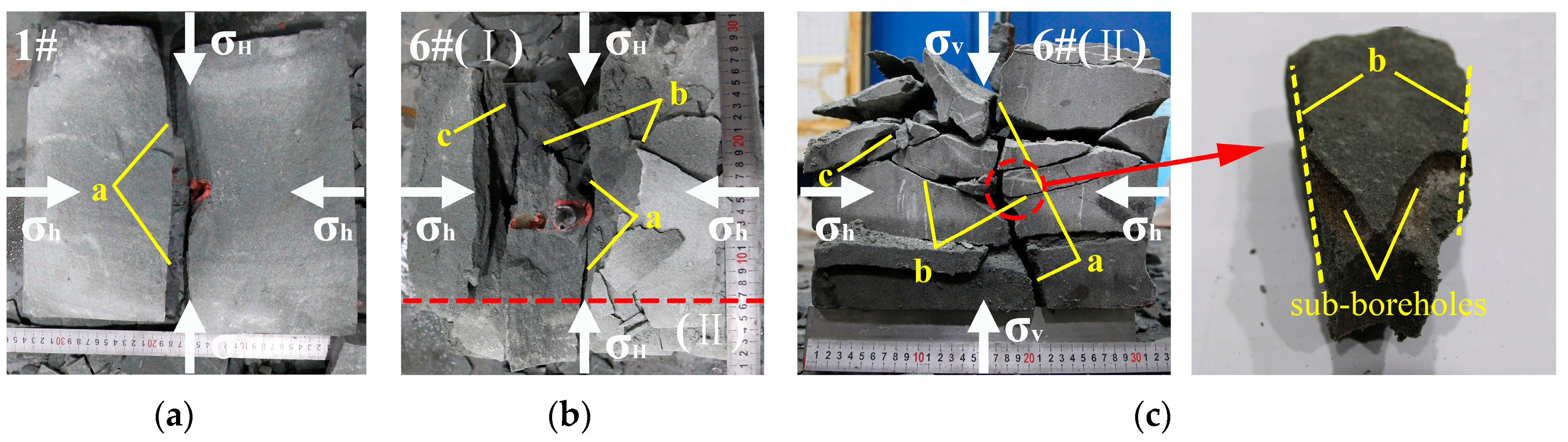
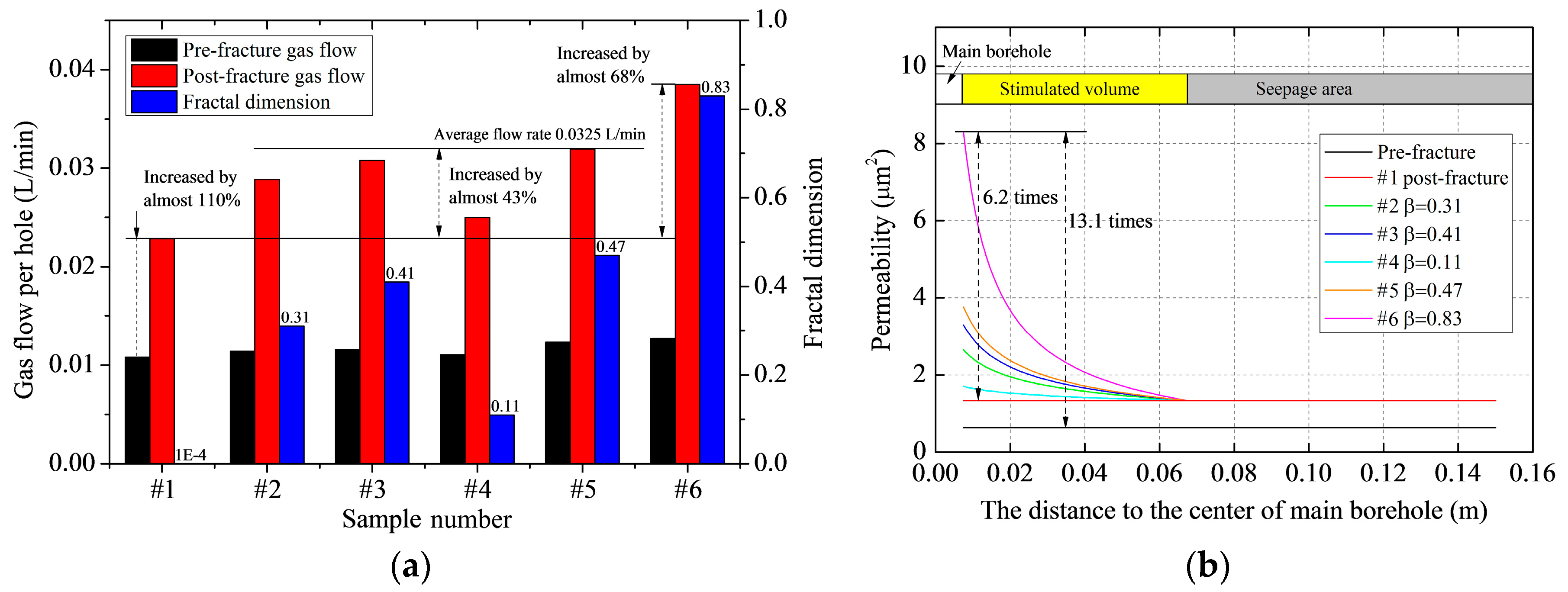
3.3. Results

The fracture morphologies of fractured samples are shown in Figure 4. The fracture morphologies in these samples show some similarities and some differences. Fractures can be divided into three types: (1) Type-a, main fractures perpendicular to the direction of minimum principal stress; (2) Type-b, tangential fractures propagating along the adjacent sub-boreholes and distributing on both sides of sub-boreholes; (3) Type-c, radial fractures changing direction to propagate along the direction perpendicular to minimum principal stress. Sample #1 is the general one not being drilled tree-type boreholes in it. There are only single Type-a main fractures induced in sample #1. Samples #2–#6 were implemented tree-type drilling and fracturing. The results of fracture morphology show that the induced fractures in sample #4 are similar to that in sample #1, and no complex fracture network is formed. For samples #2, #3, #5 and #6, Type-a main fractures, multiple Type-b and Type-c secondary fractures are induced together to form complex fracture networks.
The induced stress values calculated from Equation (2) under experimental conditions are shown in Table 1. Comparing the calculation results of samples #2, #3 and #4, the induced stress increases with the horizontal stress difference increasing under the certain construction parameters of tree-type drilling. When the horizontal stress difference (4 Mpa, 5 MPa) is less than the induced stress (5.69 MPa, 5.23 MPa), it shows that fractures are induced around the sub-boreholes and propagate to the adjacent hole. After propagating a certain distance, the fractures change direction to propagate along the direction perpendicular to the minimum principal stress. When the horizontal stress difference is increased to 6 MPa, greater than the induced stress (3.80 MPa), there are only main fractures formed at the ends of the sub-boreholes perpendicular to the minimum principal stress direction. When the horizontal ground stress difference is more than induced stress (sample #4) and the test apparatus cannot form complex fractures, increasing the number of sub-boreholes to 4 or 6 (samples #5 and #6) will increase the induced stress to 6.88 MPa or 7.64 MPa, greater than the horizontal stress difference again. This results in the formation of reticular fractures (Table 1, Figure 4).
The results from the gas seepage experiments are shown in Figure 5a. The gas flow rate in sample #1 before fracturing was 0.0108 L/min and it increased to 0.0228 L/min after conventional HF, an increase of approximately 110%. Samples #2, #3, #5 and #6 were fractured with tree-type fracturing, and their average gas flow increased by 43% more than the increase in gas flow for sample #1 after conventional HF. In sample #6, the sample with the best fracture connectivity, the post-fracturing gas flow was 0.0385 L/min, 68% higher than that of conventionally fractured sample and over 250% higher than sample #6’s non-fractured gas flow.
The fractal dimension for each sample can be calculated according to Equation (9) assuming that: (1) the radius of influence for the tree-type fracturing (the yellow Area 2 in Figure 2b) is the length of sub-boreholes; and (2) the permeability of seepage area (Area 1 in Figure 2b) is the permeability of sample #1 after being fractured by conventional HF. Fractal dimensions calculated from Equation (9) are shown in Figure 5a. When the in situ stress difference is small, Type-b fractures only form near the main borehole and the range of their influence is small (sample #2). Compared with the other samples, the overall fracture connectivity is poor and the fractal dimension is small (only 0.31). As the ground stress difference increases to approximately equal the induced stress, Type-b fractures are more uniformly distributed and they are effectively connected to each of the sub-boreholes (sample #3) and the fractal dimension is 0.41. When in situ stress difference continues to increase to be greater than the induced stress, only a single Type-a fracture is formed (sample #4). In this case, fracture connection is poor and the fractal dimension is small at 0.11.
These experiments have shown that smaller angles between the sub-boreholes are more favorable for the formation of complex fractures and smaller angles also increase the fractal dimension. Increasing the number of sub-boreholes from three to four can increase the fractal dimension to 0.47 (sample #5), and drilling six sub-boreholes increases the fractal dimension to 0.83 (sample #6). The permeabilities for each sample calculated using Equation (9) are shown in Figure 5b. In the regions near the main borehole (r = rw), the fractal dimension of the fractures is 0.83 and the permeability of the tree-type fracturing zone is 8.31 μm2, approximately 6.2 times the permeability in the conventionally fractured sample and 13.1 times the permeability in the non-fractured rock.
In summary, the in situ stress difference is the most important factor for determining whether large-radius connected reticular fractures will form. When this new fracturing technology is used in a mine, the radius of the volume of fractured rock and the connectivity of the fractures can be increased by reducing the angle between sub-boreholes to make the effective radius for gas extraction reach requirements.

4. Tree-Type Fracturing Case Study

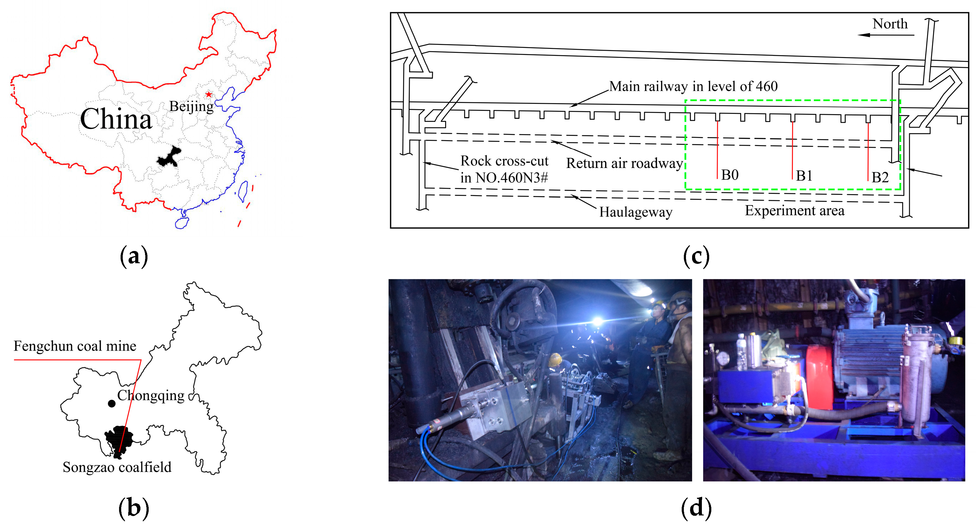
4.1. Test Site and Procedures

Laboratory experiments have confirmed the tree-type fractures propagation rules and the permeability improvement mechanism. In order to verify the feasibility of tree-type fracturing technique in coal seams, the field experiment was carried out. For the case study, the test site was in the 460 main roadway under the Fengchun coal mine, Chongqing, Southwest China (Figure 6a,b). The No. 8 coal seam, average thickness 2.29 m, was the seam used for the tree-type fracturing test. The seam’s gas content is 22.18 m3/t, the porosity is 4.52%, and the permeability coefficient is 0.015 m2/(MPa2.d). Both the roof and the floor are silty sandstone. The field B0, B1 and B2 boreholes were drilled crossing the sandstone floor to the coal seams. Because the tree-type fracturing was conducted in the coal seam, the parts of boreholes in the sandstone floor were sealed. The vertical distance from the main roadway to the seam is 32 m. Three main boreholes 87 mm in diameter separated from each other by 150 m were drilled from the main roadway to the seam. A borehole designated as B0 was used to test gas drainage without conducting any fracturing, a borehole called B1 was fractured by conventional hydraulic fracturing, and a B2 borehole was used to test tree-type fracturing. An underground drill with specialized tree-type drilling gear attached was used to drill four tree-type sub-boreholes in the No. 8 coal seam from the end of borehole B2 (Figure 6d). The average length of the sub-boreholes was 8.32 m, and the angle between sub-boreholes was 90°. After drilling was completed, the two main boreholes were sealed so they could be fractured in turn. During fracturing, the injection pressure fluctuated for a time and then suddenly dropped, indicating that the fracturing had been completed. After fracturing, gas drainage pipelines were inserted to drain CBM.

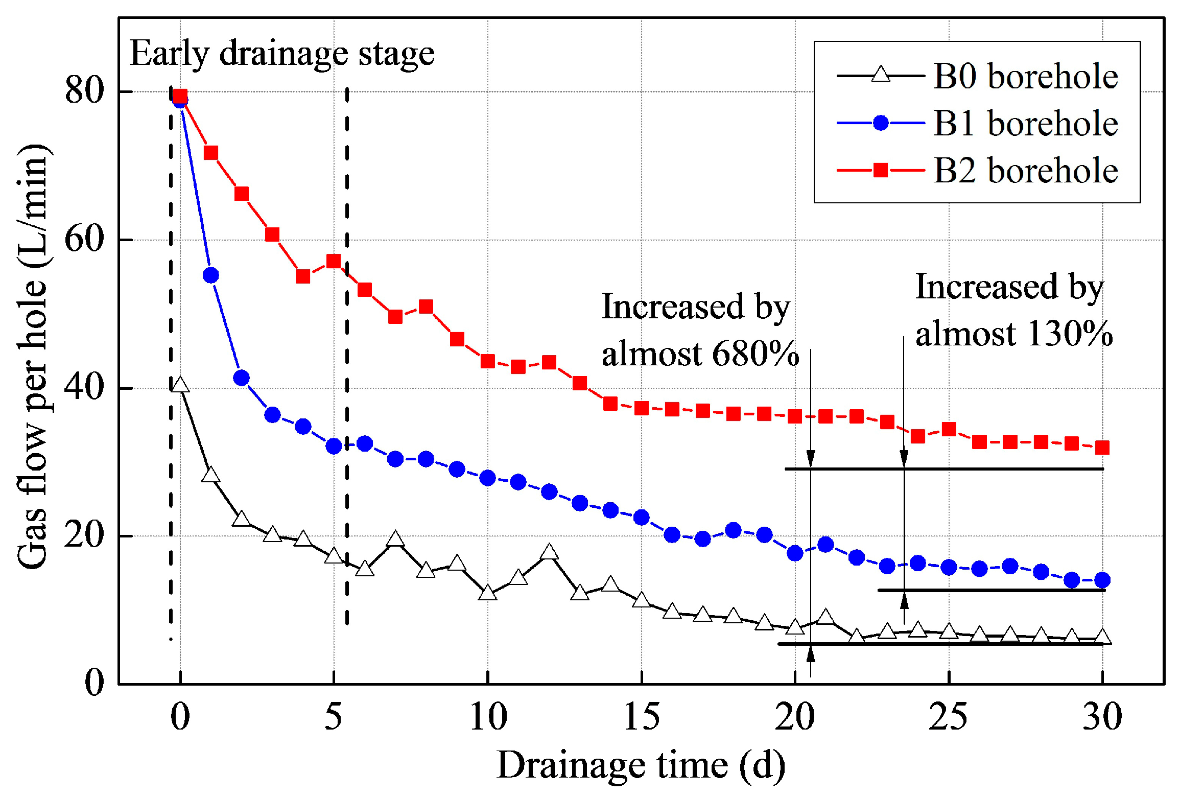
4.2. Results and Discussion

In the early stages of fracturing, the water injection pressure in both the two main boreholes rose rapidly. The pressure in the B2 borehole rose to 12.5 MPa and then wavered in a small range as fractures initiated and propagated. After about 28 min, the pressure began to decline. This showed that fractures between the sub-boreholes had become interconnected and fracturing was completed. In the B1 borehole, the pressure rose continuously and remained around 18.2 MPa for a period of time but after 11 min, the pressure dropped rapidly. Comparing the results from these two holes shows that the pressure needed for fracture propagation in tree-type boreholes is smaller than that needed for conventional fracturing in a single main borehole. The time needed for the tree-type fracturing was longer, but presumably a number of different kinds of fractures were initiated and developed.
The CBM drainage rates and the total amount of CBM drained from boreholes B0, B1 and B2 were vastly different. As shown in Figure 7, at first the gas drainage rates from boreholes B1 and B2 were both close to 80 L/min. The initial drainage rate after traditional fracturing in borehole B0 was about half as fast. After 30 days, the rate from the B1 borehole had reduced to 14.04 L/min. However, the rate of drainage from the B2 borehole attenuated relatively slowly. After 30 days, the drainage rate was still as much as 31.92 L/min, about 2.3 times that of the B1 borehole. Comparing tree-type fracturing with the traditional fracturing, the gas extraction from the tree-type fractured borehole remained at a high level for a much longer time than did gas extraction from the conventionally fractured hole. This shortened the gas drainage time and improved the overall efficiency of gas extraction.
Comprehensive analysis shows that tree-type fracturing is much more effective for extracting gas from a coal seam than conventional hydraulic fracturing. This new type of fracturing can increase coal seam permeability and improve the efficiency of gas extraction.

5. Conclusions

Based on the conventional hydraulic fracturing technology used for CBM exploitation in underground coal mines, this paper proposes a new technique of tree-type fracturing for stimulating reservoir volumes to improve gas production. This technique uses a self-propelled bit to drill tree-type boreholes. After drilling, hydraulic fracturing is conducted to generate complex, interconnected fracture networks. This fracturing method can effectively solve the problem of “blank area”, that is, volume of coal from which little or no gas can be extracted. These “blank areas” are commonly left if conventional hydraulic fracturing is used. Additionally, the new method also improves gas extraction efficiency.
The role of sub-boreholes in fracture propagation and the gas seepage after tree-type fracturing is analyzed theoretically. A model for calculating the induced stress in sub-boreholes is proposed and used to establish criteria for forming complex fractures. For a fracture to change the direction in which it propagates, the induced stress difference must be larger than the difference in the initial reservoir horizontal principal stresses. A steady state borehole fracturing productivity model was built to evaluate the fracturing effect and it shows that the fracturing radius and the connectivity of complex fractures are the decisive factors for CBM productivity.
In order to investigate the fracture morphology after implementing tree-type fracturing, simulation experiments using a large-scale true-triaxial fracturing test apparatus were conducted in the laboratory. Experimental results show that conventional hydraulic fracturing only induces single main fractures, whereas tree-type fracturing forms several main fractures plus multiple radial and tangential fractures. These fractures form complex, interconnected fracture networks. Gas seepage tests carried out after tree-type fracturing show that gas flow rates are greatly improved. As a result, gas flow in samples fractured by tree-type fracturing was as much as 68% higher than gas flow in a sample fractured by conventional hydraulic means.
Equipment for tree-type fracturing for CBM extraction in underground coal mines was developed. Moreover, field tests in the Chinese Fengchun mine show that after implementing tree-type fracturing in a borehole, the gas extraction rate was 2.3 times greater than the rate at which gas could be extracted from a borehole fractured using traditional methods. In addition, the rate at which gas was extracted from the tree-type fractured borehole remained at a high level for an extended period during a 30-day test. This shortened the gas drainage time and improved the efficiency of gas extraction. The field tests also show that the tree-type fracturing equipment is reliable, can be used in working underground mines, and can be applied to stimulate CBM production.

Acknowledgments

This study was financially supported by the National Natural Science Foundation of China (NSFC) under Grant No. 51374258 and No. 51504046, Program for Changjiang Scholars and Innovative Research Team in the University of China under Grant No. IRT13043.

Author Contributions

Qian Li, Yiyu Lu and Zhe Zhou contributed to designing the experiments, analyzing the results and writing the paper; Zhaolong Ge, Jingwei Zheng and Songqiang Xiao performed experiments.

Conflicts of Interest

The authors declare no conflict of interest.

References

  1. Tian, L.; Cao, Y.X.; Chai, X.Z.; Liu, T.J.; Feng, P.W.; Feng, H.M.; Zhou, D.; Shi, B.; Oestreich, R.; Rodvelt, G. Best practices for the determination of low-pressure/permeability coalbed methane reservoirs, Yuwu Coal Mine, Luan mining area, China. Fuel 2015, 160, 100–107. [Google Scholar] [CrossRef]
  2. Hu, G.Z.; Xu, J.L.; Zhang, F.X.; Zhao, C.C.; Qin, W.; Zhu, Y.R. Coal and coalbed methane co-extraction technology based on the ground movement in the Yangquan coalfield, China. Energies 2015, 8, 6881–6897. [Google Scholar] [CrossRef]
  3. Ranathunga, A.S.; Perera, M.S.A.; Ranjith, P.G. Deep coal seams as a greener energy source: A review. J. Geophys. Eng. 2014, 11, 063001. [Google Scholar] [CrossRef]
  4. Mu, C.M.; Wang, H.L.; Huang, W.Y.; Kuang, C.J. Increasing permeability mechanism using directional cumulative blasting in coal seams with high concentration of gas and low permeability. Rock Soil Mech. 2013, 34, 2496–2500. [Google Scholar]
  5. Lu, T.K.; Yu, H.; Zhou, T.Y.; Mao, J.S.; Guo, B.H. Improvement of methane drainage in high gassy coal seam using waterjet technique. Int. J. Coal Geol. 2009, 79, 40–48. [Google Scholar] [CrossRef]
  6. Kong, X.G.; Wang, E.Y.; Liu, X.F.; Li, N.; Chen, L.; Feng, J.J.; Kong, B.; Li, D.X.; Liu, Q.L. Coupled analysis about multi-factors to the effective influence radius of hydraulic flushing: Application of response surface methodology. J. Nat. Gas Sci. Eng. 2016, 32, 538–548. [Google Scholar] [CrossRef]
  7. Zhang, Z.B.; Li, X. Numerical study on the formation of shear fracture network. Energies 2016, 9, 299. [Google Scholar] [CrossRef]
  8. Westwood, R.F.; Toon, S.M.; Styles, P.; Cassidy, N.J. Horizontal respect distance for hydraulic fracturing in the vicinity of existing faults in deep geological reservoirs: A review and modelling study. Geomech. Geophys. Geo-Energy Geo-Resour. 2017, 3, 1–13. [Google Scholar] [CrossRef]
  9. Huang, B.X.; Liu, C.Y.; Fu, J.H.; Guan, H. Hydraulic fracturing after water pressure control blasting for increased fracturing. Int. J. Rock Mech. Min. Sci. 2011, 48, 976–983. [Google Scholar] [CrossRef]
  10. Zhai, C.; Li, M.; Sun, C.; Zhang, J.G.; Yang, W.; Li, Q.G. Guiding-controlling technology of coal seam hydraulic fracturing fractures extension. Int. J. Min. Sci. Technol. 2012, 22, 831–836. [Google Scholar] [CrossRef]
  11. Fan, J.; Dou, L.M.; He, H.; Du, T.T.; Zhang, S.B.; Gui, B.; Sun, X.L. Directional hydraulic fracturing to control hard-roof rockburst in coal mines. Int. J. Min. Sci. Technol. 2012, 22, 177–181. [Google Scholar] [CrossRef]
  12. Wang, Y.F.; Li, Y.Z. Technology and application of directional hydraulic penetration permeability improvement by guided groove. J. China Coal Soc. 2012, 37, 1326–1331. [Google Scholar]
  13. Liu, Y.; Xia, B.W.; Liu, X.T. A novel method of orienting hydraulic fractures in coal mines and its mechanism of intensified conduction. J. Nat. Gas Sci. Eng. 2015, 27, 190–199. [Google Scholar] [CrossRef]
  14. Zou, Q.L.; Lin, B.Q.; Zheng, C.S.; Hao, Z.Y.; Zhai, C.; Liu, T.; Liang, J.Y.; Yan, F.Z.; Yang, W.; Zhu, C.J. Novel integrated techniques of drilling-slotting-separation-sealing for enhanced coal bed methane recovery in underground coal mines. J. Nat. Gas Sci. Eng. 2015, 26, 960–973. [Google Scholar] [CrossRef]
  15. Yan, F.Z.; Lin, B.Q.; Zhu, C.J.; Shen, C.M.; Zou, Q.L.; Guo, C.; Liu, T. A novel ECBM extraction technology based on the integration of hydraulic slotting and hydraulic fracturing. J. Nat. Gas Sci. Eng. 2015, 22, 571–579. [Google Scholar] [CrossRef]
  16. Kozlowska, M.; Orlecka-Sikora, B.; Rudzinski, L.; Cielesta, S.; Mutke, G. A typical evolution of seismicity patterns resulting from the coupled natural, human-induced and coseismic stresses in along wall coal mining environment. Int. J. Rock Mech. Min. Sci. 2016, 86, 5–15. [Google Scholar]
  17. Lu, Y.Y.; Zhou, Z.; Ge, Z.L.; Zhang, X.W.; Li, Q. Research on and design of a self-propelled nozzle for the tree-type drilling technique in underground coal mines. Energies 2015, 8, 14260–14271. [Google Scholar] [CrossRef]
  18. Green, A.E.; Sneddon, I.N. The distribution of stress in the neighbourhood of a flat elliptical crack in an elastic solid. Math. Proc. Camb. Philos. Soc. 1950, 46, 159–163. [Google Scholar] [CrossRef]
  19. Palmer, I.D. Induced Stresses Due to Propped Hydraulic Fracture in Coalbed Methane Wells. In Proceedings of the Low Permeability Reservoirs Symposium, Denver, CO, USA, 26–28 April 1993. [Google Scholar]
  20. Pollard, D.D.; Holzhausen, G. On the mechanical interaction between a fluid-filled fracture and the earth’s surface. Tectonophysics 1979, 53, 27–57. [Google Scholar] [CrossRef]
  21. Olson, J.E. Joint pattern development: Effects of subcritical crack growth and mechanical crack interaction. J. Geophys. Res. 1993, 98, 12251–12265. [Google Scholar] [CrossRef]
  22. Cipolla, C.L.; Warpinski, N.R.; Mayerhofer, M.J.; Lolon, E.P.; Vincent, M.C. The relationship between fracture complexity, reservoir properties, and fracture-treatment design. Soc. Pet. Eng. 2010, 25, 438–452. [Google Scholar] [CrossRef]
  23. Willis-Richards, J.; Watanabe, K.; Takahashi, H. Progress toward a stochastic rock mechanics model of engineered geothermal systems. J. Geophys. Res. 1996, 101, 17481–17496. [Google Scholar] [CrossRef]
  24. Hossain, M.M.; Rahman, M.K.; Rahman, S.S. A shear dilation stimulation model for production enhancement from naturally fractured reservoirs. Soc. Pet. Eng. 2002, 7, 183–195. [Google Scholar] [CrossRef]
  25. Rubin, B. Accurate simulation of non-darcy flow in stimulated fractured shale reservoirs. Soc. Pet. Eng. 2010. [Google Scholar] [CrossRef]
  26. Braester, C.; Thunvik, R. Determination of formation permeability by double-packer tests. J. Hydrol. 1984, 72, 375–389. [Google Scholar] [CrossRef]
  27. Xu, R.T.; Li, H.J.; Guo, C.C.; Hou, Q.L. The mechanisms of gas generation during coal deformation: Preliminary observations. Fuel 2014, 117, 326–330. [Google Scholar] [CrossRef]
  28. Viete, D.R.; Ranjith, P.G. The mechanical behaviour of coal with respect to CO2 sequestration in deep coal seams. Fuel 2007, 86, 2667–2671. [Google Scholar] [CrossRef]
  29. Ranathunga, A.S.; Perera, M.S.A.; Ranjith, P.G.; Wei, C.H. An experimental investigation of applicability of CO2 enhanced coal bed methane recovery to low rank coal. Fuel 2017, 189, 391–399. [Google Scholar] [CrossRef]
  30. Ranathunga, A.S.; Perera, M.S.A.; Ranjith, P.G.; Sliva, G.P.D.D. A macro-scale view of the influence of effective stress on carbon dioxide flow behaviour in coal: An experimental study. Geomech. Geophys. Geo-Energy Geo-Resour. 2017, 3, 13–28. [Google Scholar] [CrossRef]
  31. Pride, S.R.; Berryman, J.G.; Commer, M.; Nakagawa, S.; Newman, G.A.; Vasco, D.W. Changes in geophysical properties caused by fluid injection into porous rocks: Analytical models. Geophys. Prospect. 2017, 65, 766–790. [Google Scholar] [CrossRef]
Figure 1. Illustrations showing (a) the equipment used for tree-type drilling and fracturing for gas drainage in underground coal mines and (b) tree-type sub-boreholes and the fractures propagated from them.
Energies 10 01388 g001
Figure 2. (a) Image of tree-type sub-boreholes and a diagram showing a two-dimensional plane strain model for the stress field around tree-type sub-boreholes; (b) Diagrammatic sketch showing the gas flow through a fracture network formed by tree-type drilling and fracturing.
Energies 10 01388 g002
Figure 3. (a) Diagram showing the components that make up the large-scale true-triaxial hydraulic fracturing test apparatus; (b) Photograph of the apparatus shown in (a); (c) Load-bearing cover that seals the test apparatus sample carrier; (d) The triaxial test apparatus loading cavity.
Energies 10 01388 g003
Figure 4. Images showing the samples after fracturing. (a) The sample #1 after conventional fracturing; (b) The sample #6 after tree-type fracturing; (c) The partial enlarged drawing of sample #6. The fracture morphology of sample #4 is similar to that of sample #1, and the fracture morphologies of samples #2, #3 and #5 are similar to that of sample #6. Image (I) is vertical view, and image (II) is front view.
Energies 10 01388 g004
Figure 5. Gas seepage experimental results after tree-type fracturing. (a) Gas flow rates and fractal dimension; (b) Permeability.
Energies 10 01388 g005
Figure 6. Maps showing the location of the field test study site and photographs of the drilling equipment. (a) Location of Chongqing province in China; (b) Location of the Songzao coalfield and the Fengchun mine, Chongqing province; (c) Plan showing the roadway layout of mining area No. 8 and the location of the roadway for gas drainage below the mechanical roadway in the Fengchun mine; (d) The equipment used for tree-type drilling.
Energies 10 01388 g006
Figure 7. Comparison of the gas drainage rates for three boreholes. B0 not fractured; B1 fractured using conventional hydraulic fracturing; B2 fractured using tree-type hydraulic fracturing.
Energies 10 01388 g007
Table 1. Experimental conditions for tree-type triaxial fracturing experiments.
Sample NumberTriaxial Stresses σv/σH/σh (MPa)Horizontal Stress Difference (MPa)The Number of Sub-BoreholesInitiation Pressure (MPa)The Induced Stress (MPa)Whether Fractures Are Induced?
#115/12/84017.22--------
#215/12/84315.245.69Yes
#315/12/75314.025.23Yes
#415/12/66310.183.80No
#515/12/66410.066.88Yes
#615/12/6669.257.64Yes
σv is the vertical stress in MPa, σH is the maximum horizontal stress in MPa, and σh is the minimum horizontal stress in MPa.

