
Modeling and Analysis of the Common Mode Voltage in a Cascaded H-Bridge Electronic Power Transformer


Abstract
:1. Introduction
- Due to the long power cables connecting to the grid or motors, the traveling high-rise-rate CMV wave reflected by the terminals of cables will further result in overvoltage for terminal devices and cause bearing currents that reduce the life of the motors.
- High may cause leakage currents through the parasitic capacitances, which also damage the insulation of elements in the devices, e.g., power cables; in addition, it also creates electromagnetic interference problems, which will interfere with the control systems of devices.
2. Description of the CMV in a CHB-EPT
2.1. CHB-EPT System
2.2. The CMV at the High-Voltage Side in the EPT System
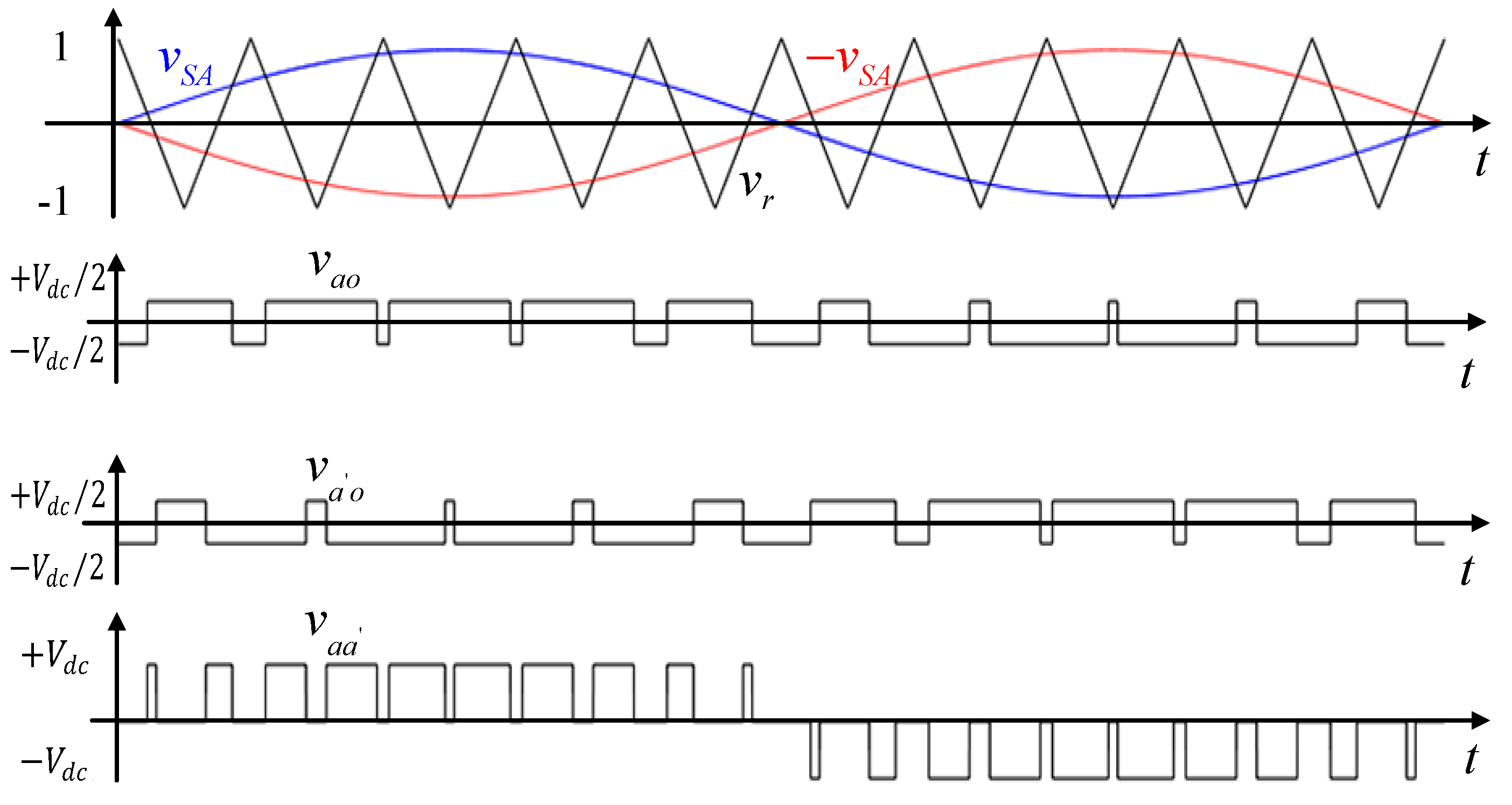
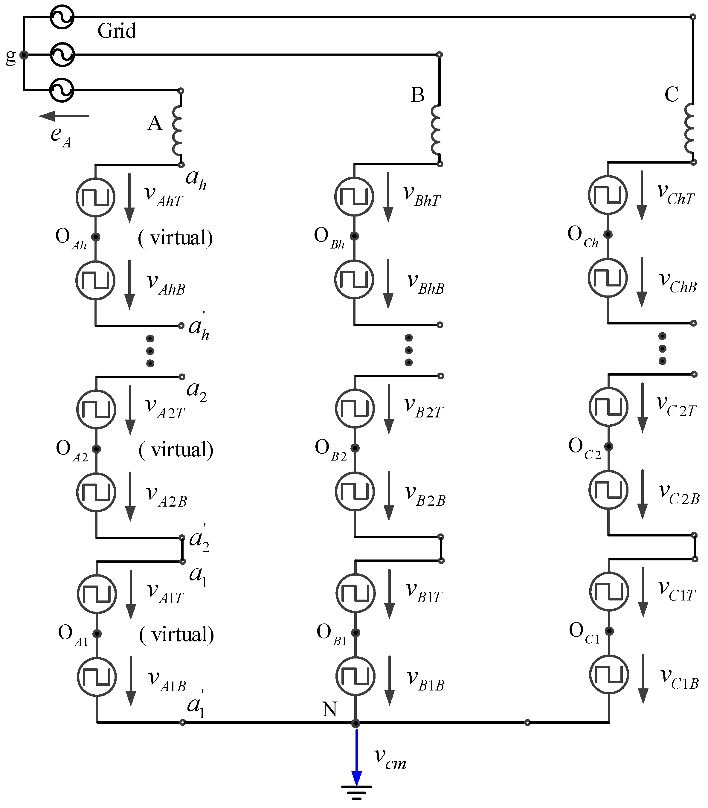
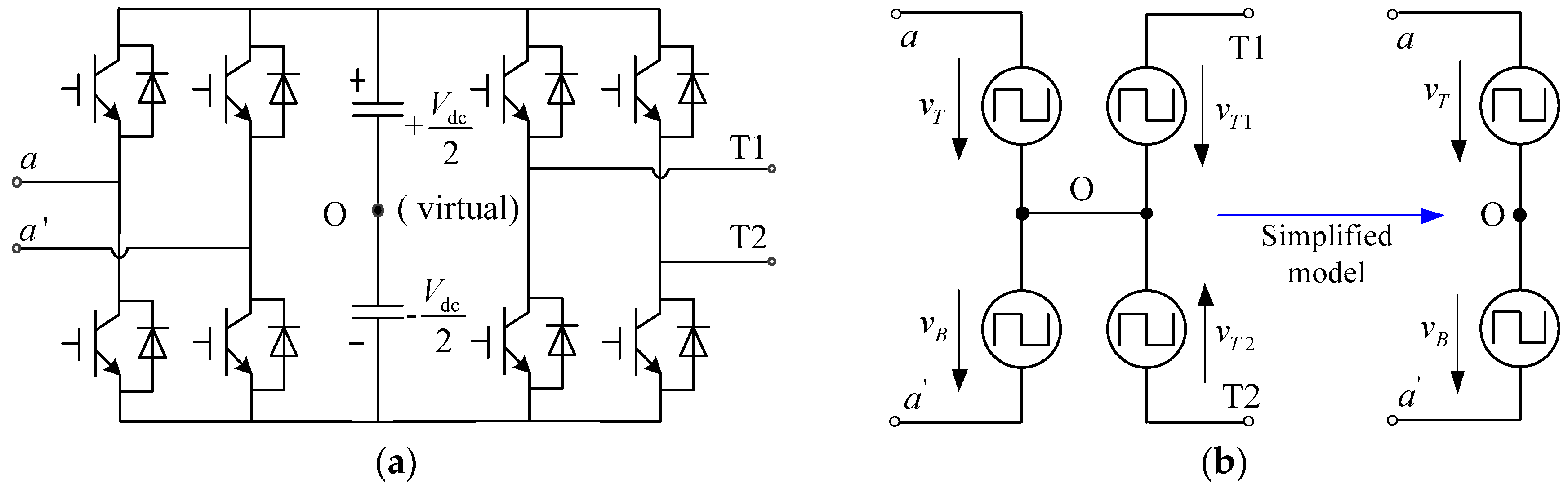
2.2.1. Voltages Generated by the HVPC
2.2.2. The CMV at Neutral Point
- Normal grid: For the three-phase balanced power grid, the voltage between the virtual grid neutral g (see the location in Figure 4) and ground can be assumed as zero so the neutral point of the grid can be chosen as the reference ground directly; then we have .
- Single-phase to ground fault: The voltage between the neutral point g of the grid and ground will shift up to phase voltage when a single-phase to ground fault occurs. For a balanced EPT, the CMV at neutral point N with respect to ground will be shifted synchronously. Then we have:where is the voltage between the neutral point of the grid in Figure 4 and ground.
2.2.3. Voltages with Respect to Ground in HVPCs
3. Analytical Calculation of Voltages in EPT
3.1. Principle and Method to Calculate Voltages in EPT System
- (1)
- Calculate the CMV at neutral point N with respect to ground, i.e., .
- (2)
- Calculate the voltage between and N, that is:where x = {A, B, C}, L = 1, 2… h.
- (3)
- Finally, obtain the voltage potential with respect to ground in HVPC L based on Equation (5).
3.2. Derivation and Calculation of the CMV at Neutral Point and Voltage Potential of HVPCs
3.2.1. The CMV with Respect to Ground at a Neutral Point
3.2.2. The Voltage with Respect to N at Point
3.2.3. Voltage Potential of HVPCs
3.3. Analysis of the Voltages
3.3.1. Analysis of the CMV with Respect to Ground at Neutral Point
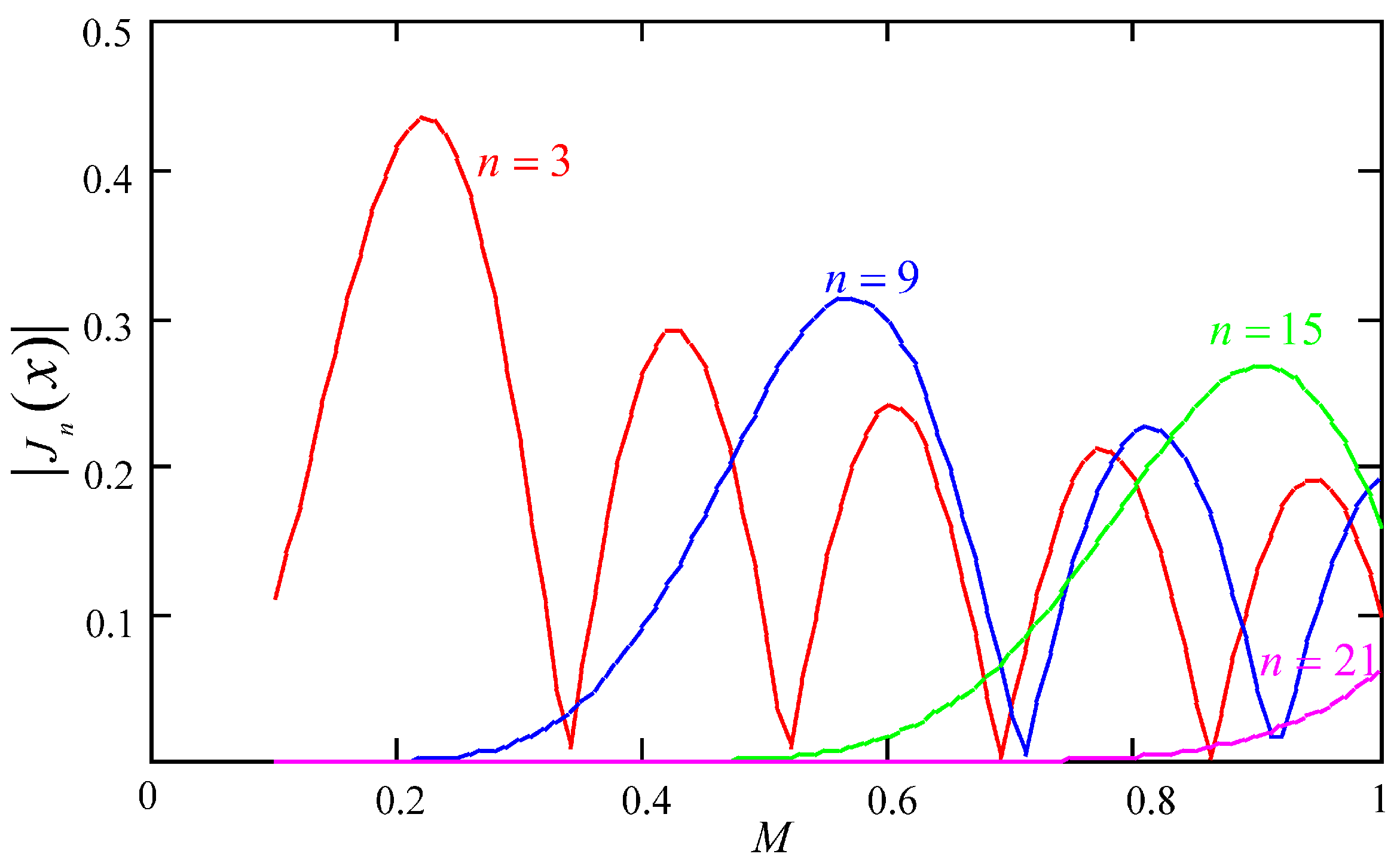
- (1)
- The relationship between the amplitude of the CMV harmonics component and the modulation ratio M
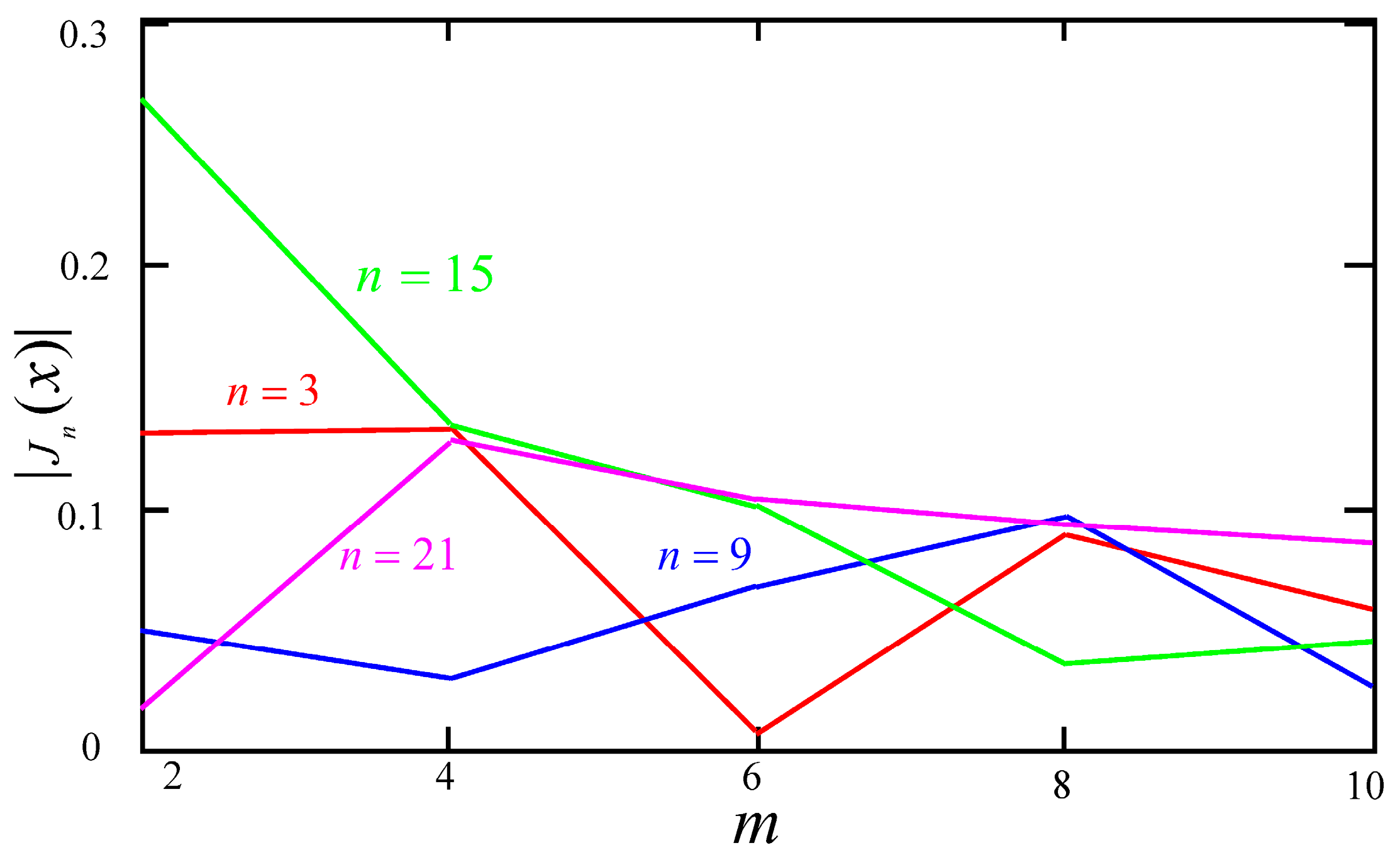
- (2)
- The relationship between the amplitude of CMV harmonics and its order
3.3.2. Analysis of the Voltage with Respect to Ground at Midpoint
3.4. Effects of SPWM Dead Time on the CMV
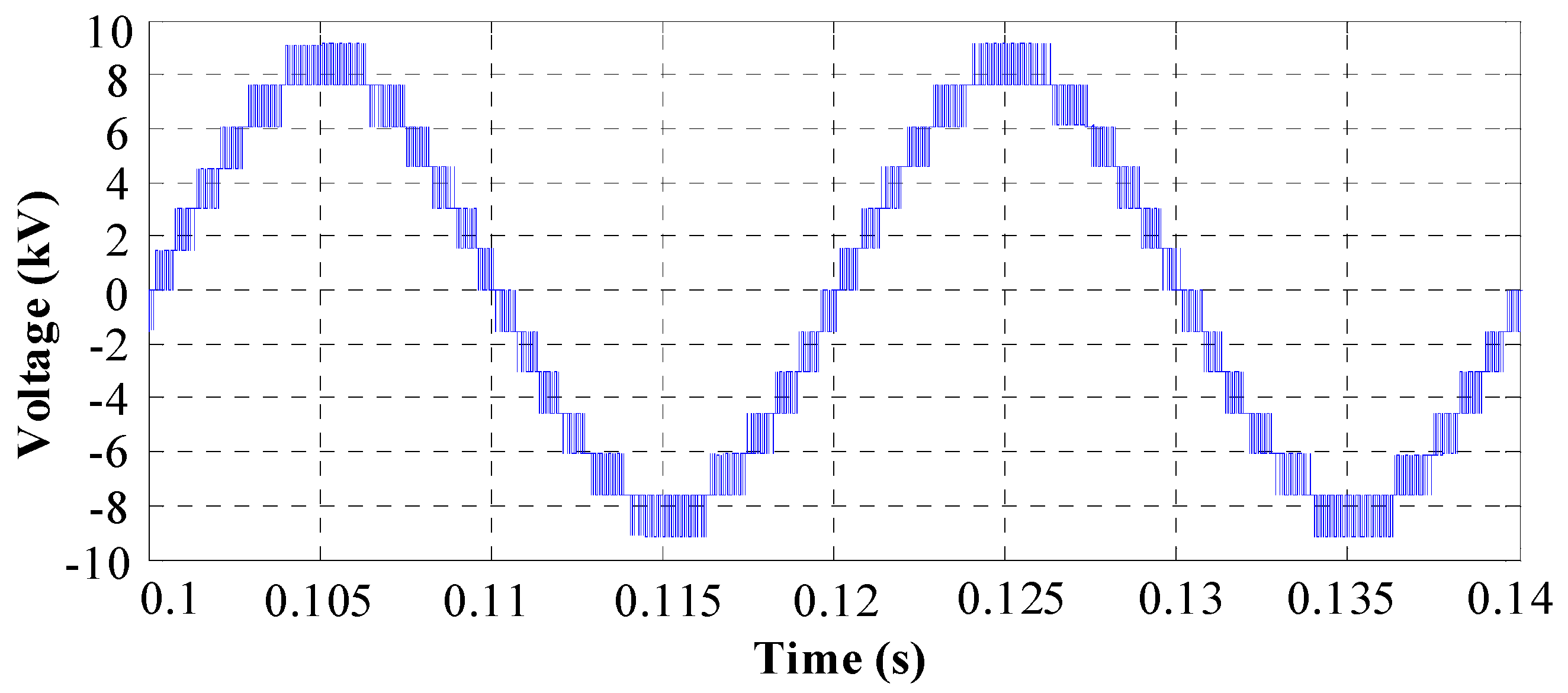
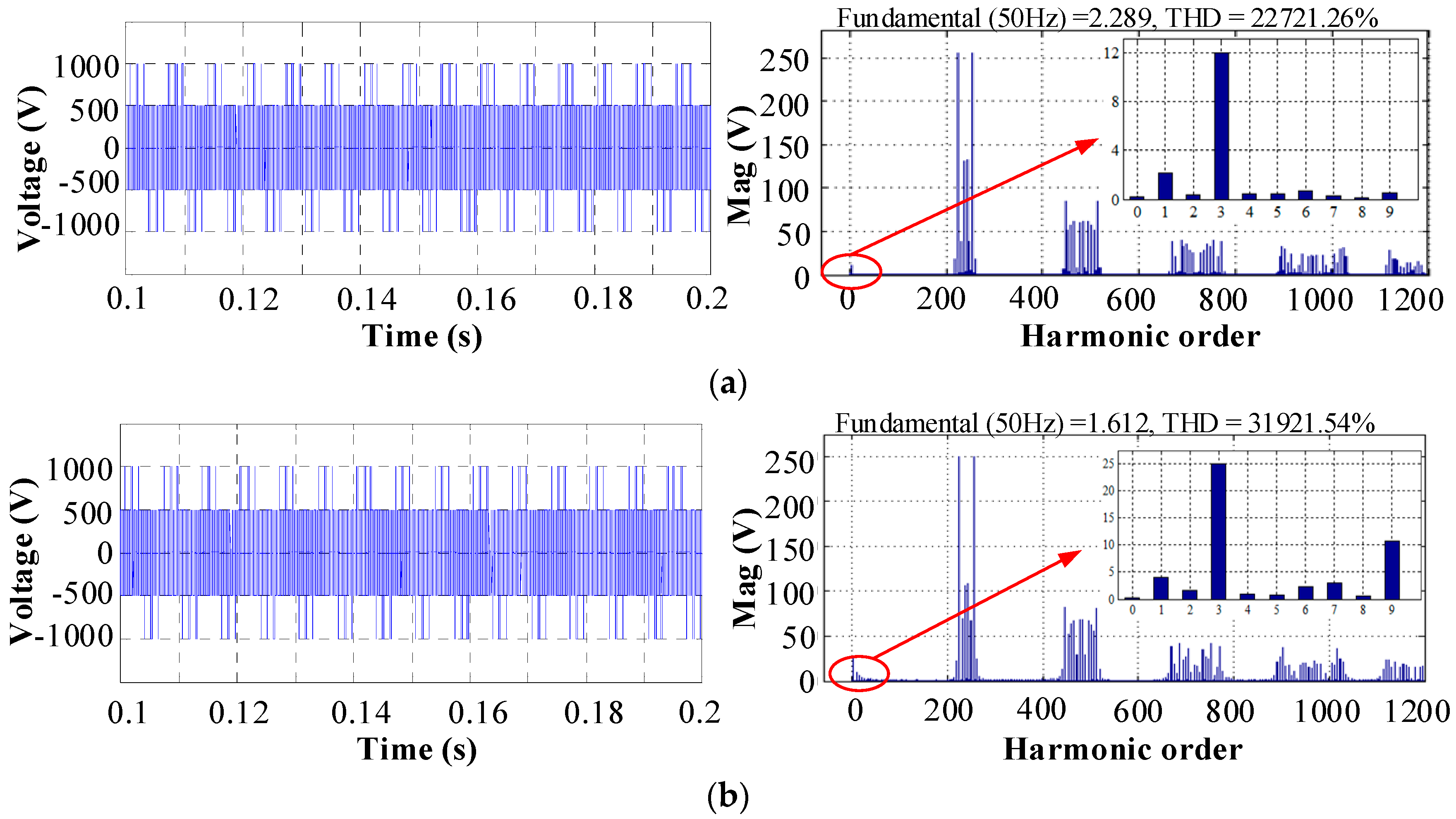
4. Simulation Results
5. Conclusions
- The CMV at the neutral point N under normal and balanced grid voltage conditions mainly consists of high-order harmonics with relatively high voltage stress for the high-voltage side of the EPT. The EPT has to sustain a higher fundamental component of the CMV, i.e., the voltage of the fault phase, when it operates under a fault grid condition (single-phase to ground fault).
- The voltage potential at each equivalent midpoint of the HVPC with respect to ground, not only includes the high-order harmonics components, but also contains the line-frequency fundamental component. Furthermore, the magnitude of the latter will increase with an increase of the sequence number of the HVPC. Obviously, the highest electrical stress will appear in the top HVPC, which provides a theoretical guide for the structural design and further power density optimization of the EPT.
- SPWM dead time has little effect on the magnitude of the CMV. In addition, it will not bring a fundamental component to the CMV at the neutral point.
Acknowledgments
Author Contributions
Conflicts of Interest
References
- Yan, B.; Wang, B.; Zhu, L. A novel, stable, and economic power sharing scheme for an autonomous microgrid in the energy internet. Energies 2015, 8, 12741–12764. [Google Scholar] [CrossRef]
- Liserre, M.; Sauter, T.; Hung, J.Y. Future energy systems: Integrating renewable energy sources into the smart power grid through industrial electronics. IEEE Ind. Electron. Mag. 2010, 4, 18–37. [Google Scholar] [CrossRef]
- Huang, A.Q.; Crow, M.L.; Heydt, G.T.; Zheng, J.P.; Dale, S.J. The future renewable electric energy delivery and management (FREEDM) system: The energy internet. Proc. IEEE 2011, 99, 133–148. [Google Scholar] [CrossRef]
- Yang, Y.; Mao, C.; Wei, T.; Wang, D.; Tian, J. Multi-function combined operation and control strategy of electronic power transformer for power quality improvement. IEEJ Trans. Electr. Electron. 2017. [Google Scholar] [CrossRef]
- Wang, D.; Tian, J.; Mao, C.; Lu, J.; Duan, Y.; Qiu, J.; Cai, H. A 10-kV/400-V 500-kVA electronic power transformer. IEEE Trans. Ind. Electron. 2016, 63, 6653–6663. [Google Scholar] [CrossRef]
- She, X.; Huang, A.Q.; Burgos, R. Review of solid-state transformer technologies and their application in power distribution systems. IEEE J. Emerg. Sel. Top. Power Electron. 2013, 1, 186–198. [Google Scholar] [CrossRef]
- Brando, G.; Dannier, A.; del Pizzo, A.; Rizzo, R. Power electronic transformer for advanced grid management in presence of distributed generation. Int. Rev. Electr. Eng. (IREE) 2011, 6, 3009–3015. [Google Scholar]
- Kolar, J.W.; Ortiz, G. Solid-state-transformers: Key components of future traction and smart grid systems. In Proceedings of the International Power Electronics Conference-ECCE Asia (IPEC 2014), Hiroshima, Japan, 18–21 May 2014. [Google Scholar]
- She, X.; Huang, A.Q. Solid state transformer in the future smart electrical system. In Proceedings of the IEEE Power and Energy Society General Meeting, Vancouver, BC, Canada, 21–25 July 2013; pp. 1–5. [Google Scholar]
- Huang, P.; Mao, C.; Wang, D. Electric field simulations and analysis for high voltage high power medium frequency transformer. Energies 2017, 10, 3. [Google Scholar] [CrossRef]
- Yang, J.; Mao, C.; Wang, D.; Lu, J.; Fu, X.; Chen, X. Fast and continuous on-load voltage regulator based on electronic power transformer. IET Electr. Power Appl. 2013, 7, 499–508. [Google Scholar] [CrossRef]
- Zhao, C.; Dujic, D.; Mester, A.; Steinke, J.K.; Weiss, M.; Lewdeni-Schmid, S.; Chaudhuri, T.; Stefanutti, P. Power electronic traction transformer—Medium voltage prototype. IEEE Trans. Ind. Electron. 2014, 61, 3257–3268. [Google Scholar] [CrossRef]
- Rendusara, D.A.; Cengelci, E.; Enjeti, P.N.; Stefanovic, V.R. Analysis of common mode voltage-’neutral shift’ in medium voltage PWM adjustable speed drive (MV-ASD) systems. IEEE Trans. Power Electron. 2002, 15, 1124–1133. [Google Scholar] [CrossRef]
- Tang, X.; Lai, C.; Liu, Z.; Zhang, M. A SVPWM to eliminate common-mode voltage for multilevel inverters. Energies 2017, 10, 715. [Google Scholar] [CrossRef]
- Aoki, N.; Satoh, K.; Nabae, A. Damping circuit to suppress motor terminal overvoltage and ringing in PWM inverter-fed ac motor drive systems with long motor leads. IEEE Trans. Ind. Appl. 1999, 35, 1014–1020. [Google Scholar] [CrossRef]
- Jiang, Y.; Wu, W.; He, Y.; Chung, S.H.; Blaabjerg, F. New passive filter design method for overvoltage suppression and bearing currents mitigation in a long cable based PWM inverter-fed motor drive system. IEEE Trans. Power Electron. 2017, 32, 7882–7893. [Google Scholar] [CrossRef]
- Lai, R.; Todorovic, M.H.; Sabate, J. Analysis and suppression of a common mode resonance in the cascaded H-bridge multilevel inverter. In Proceedings of the Energy Conversion Congress and Exposition (ECCE), Atlanta, GA, USA, 12–16 September 2010; pp. 4564–4568. [Google Scholar]
- Hava, A.M.; Ün, E. Performance analysis of reduced common-mode voltage PWM methods and comparison with standard PWM methods for three-phase voltage-source inverters. IEEE Trans. Power Electron. 2009, 24, 241–252. [Google Scholar] [CrossRef]
- Lai, Y.S.; Shyu, F.S. Optimal common-mode voltage reduction PWM technique for inverter control with consideration of the dead-time effects—Part I: Basic development. IEEE Trans. Ind. Appl. 2004, 40, 1605–1612. [Google Scholar] [CrossRef]
- Julian, A.L.; Oriti, G.; Lipo, T.A. Elimination of common-mode voltage in three-phase sinusoidal power converters. IEEE Trans. Power Electron. 1999, 14, 982–989. [Google Scholar] [CrossRef]
- Yang, B.; Li, W.; Gu, Y.; Cui, W.; He, X. Improved transformerless inverter with common-mode leakage current elimination for a photovoltaic grid-connected power system. IEEE Trans. Power Electron. 2012, 27, 752–762. [Google Scholar] [CrossRef]
- Zhou, Y.; Li, H. Analysis and suppression of leakage current in cascaded-multilevel-inverter-based PV systems. IEEE Trans. Power Electron. 2014, 29, 5265–5277. [Google Scholar] [CrossRef]
- Huber, J.E.; Kolar, J.W. Common-mode currents in multi-cell solid-state transformers. In Proceedings of the 2014 International Power Electronics Conference (IPEC), Hiroshima, Japan, 18–21 May 2014; pp. 766–773. [Google Scholar]
- Guillod, T.; Huber, J.E.; Ortiz, G.; De, A.; Franck, C.M.; Kolar, J.W. Characterization of the voltage and electric field stresses in multi-cell solid-state transformers. In Proceedings of the 2014 IEEE Energy Conversion Congress and Exposition (ECCE), Pittsburgh, PA, USA, 14–18 September 2014; pp. 4726–4734. [Google Scholar]
- Li, Y.; Wang, Y.; Li, B.Q. Generalized theory of phase-shifted carrier PWM for cascaded H-bridge converters and modular multilevel converters. IEEE J. Emerg. Sel. Topics Power Electron. 2016, 4, 589–605. [Google Scholar] [CrossRef]
- Holmes, D.; Lipo, T. Pulse Width Modulation for Power Converters: Principles and Practice, 1st ed.; Wiley: Hoboken, NJ, USA, 2003; pp. 99–119. [Google Scholar]


| Parameter | Value |
|---|---|
| Number of cascaded H-bridges | 6 per phase |
| Number of paralleled H-bridges | 6 per phase |
| Rated high voltage dc-link | 1500 V |
| Rated low voltage dc-link | 360 V |
| Capacitance in one high-voltage dc-link | 2200 |
| Capacitance in one low-voltage dc-link | 56 mF |
| Inductance of rectifier | 30 mH |
| Filter inductance of the inverter | 0.2 mH |
| Filter capacitance of the inverter | 250 |
| Rated ratio of the MFIT | 4.17:1 |
| Switching frequency at high-voltage side | 1 kHz |
| Switching frequency at low-voltage side | 4 kHz |
© 2017 by the authors. Licensee MDPI, Basel, Switzerland. This article is an open access article distributed under the terms and conditions of the Creative Commons Attribution (CC BY) license (http://creativecommons.org/licenses/by/4.0/).
Share and Cite
Yang, Y.; Mao, C.; Wang, D.; Tian, J.; Yang, M. Modeling and Analysis of the Common Mode Voltage in a Cascaded H-Bridge Electronic Power Transformer. Energies 2017, 10, 1357. https://doi.org/10.3390/en10091357
Yang Y, Mao C, Wang D, Tian J, Yang M. Modeling and Analysis of the Common Mode Voltage in a Cascaded H-Bridge Electronic Power Transformer. Energies. 2017; 10(9):1357. https://doi.org/10.3390/en10091357
Chicago/Turabian StyleYang, Yun, Chengxiong Mao, Dan Wang, Jie Tian, and Ming Yang. 2017. "Modeling and Analysis of the Common Mode Voltage in a Cascaded H-Bridge Electronic Power Transformer" Energies 10, no. 9: 1357. https://doi.org/10.3390/en10091357