1. Introduction
The bidirectional voltage source converter (BVSC) can integrate various ac/dc loads, distributed storages, distributed generation, and ac grid with high efficiency and flexible power regulation. Due to the increasing development of switching devices and renewable energy power generation, there will be more applications of bidirectional alternating current (ac)/direct current (dc) conversion, such as electric vehicles, which can store power in the night and generate power to the grid in the daytime. The growth of BVSC has been promoted by the environment pollution issues caused by the traditional fossil energy resources such as oil and coal. This has received great attention in developing countries [
1,
2]. For the high performance of the bidirectional power conversion between the ac and dc sides, the reliability of the BVSC in different working conditions, such as under unbalanced power grid, paralleled applications, or islanding mode, has been studied to ensure safe and continuous operation [
3,
4,
5]. However, much research shows that switching devices in power converters, such as an insulated gate bipolar transistor (IGBT) or a metal-oxide field-effect transistor (MOSFET), are prone to have faults caused by the surges and spikes in the conditions of high voltage and high switching frequency transition, which are a major challenge to the reliability of the power converter. On the other hand, most power converters are not designed to be redundant. Once there is a switching device fault, the power conversion will be interrupted. Therefore, the study of nonredundant fault-tolerant bidirectional power conversion is urgent and significant to enhance the reliability of the BVSC [
6,
7,
8,
9].
The three-phase four-switch (TPFS) topology was first presented for its cost-effective design, and it became a fault-tolerant topology for the switching devices open or short circuits faults of the conventional three-phase six-switch converter (TPSS) for bidirectional power conversion [
10,
11,
12,
13,
14,
15]. As a promising fault-tolerant topology for the widely used TPSS plan, the control scheme study of TPFS topology has drawn great attention. The TPFS converter is applied in motor drive applications as a low cost fault-tolerant topology. A control strategy–based single current sensor is proposed for the fault-tolerant brushless dc motor to lower cost and improve performance [
10]. A compensation scheme with different forward voltage drop values is proposed for the direct torque control of the TPFS converter to correct the stator flux imbalance and reduce the total harmonic distortion [
11]. The voltage unbalance of the dc-link split capacitors is another problem for the reliable operation of a fault-tolerant converter. The spatial repetitive controller is proposed to eliminate the dc-link central point voltage fluctuation of the TPFS converter in microgrids application [
12]. The double Fourier integral analysis is used to investigate the phase-leg switched voltage spectrum of TPFS converter. The dc-link central point voltage fluctuation can be neutralized by injecting certain terms to the modulating waveforms [
13]. A predictive torque control for TPFS inverter-fed induction motor with dc-link voltage offset suppression is proposed to balance the phase current [
14]. The TPFS inverter based on the topology of the single-ended primary-inductance converter is proposed to provide the higher output voltage, which enhances the utilization of the dc voltage [
15]. The above control method of TPFS converter is based on the space voltage vector modulation method, which needs the coordinating transformation, the complex calculation of the vector sector, and the duty ratio. Furthermore, the bidirectional power conversion of the fault-tolerant operation is not considered.
Model predictive control (MPC) has the advantages of simplicity and flexibility, and the cost function can be designed with different control objectives. Compared to classical control methods, MPC has a fast, dynamic response, good adaptability, and robustness without using the phase locked loop control and pulse width modulation (PWM) [
16,
17,
18,
19,
20]. MPC has been used in a grid-connected inverter system under normal conditions without faults. A model predictive direct power control strategy for a grid-connected inverter in a photovoltaic system is proposed, which achieve flexible power regulation and switching frequency reduction [
18]. In addition, coordinate transformation and proportional-integral regulators are not necessary. The switching table and PWM modulation module are not included either. The delay compensation method is proposed to reduce the influence of the calculation delay when there are a large number of voltage vectors [
19]. A model predictive power control method is proposed for the PWM rectifier that is able to operate under both balanced and unbalanced grid voltages [
20]. Neither complicated sequence extraction of grid voltage/current nor the phase locked loop is needed. However, this does not consider the power switching faults conditions. Although there are many studies on the model predictive control scheme of the power converter, the switching device open or short circuit faults are not considered. Therefore, the control scheme of the fault-tolerant topology needs further study.
This paper proposes a model predictive direct power control method for nonredundant fault tolerant grid-connected BVSC with high reliability. With high-penetration renewable energy and microgrids integration, the proposed method offers a higher reliability for power conversion. The main contributions of this paper are as follows:
The fault tolerant grid-connected BVSC model is established. The impacts of the unbalanced dc-link capacitor voltage on the voltage vectors are analyzed in detail.
The model predictive direct power control (MPDPC) method is designed considering direct power control and dc-link voltage balance control, which does not need double loop control, PWM modulation, or phase locked loop, and is easy to implement. The dc-link split capacitor voltage balance control is achieved by adding compensation term to the cost function, which reduces the risk of electrolytic capacitor failure for over-voltage operation.
With the proposed MPDPC, the fault-tolerant BVSC has good steady-state performance with sinusoidal output current waveforms. When the reference power changes, the fault-tolerant working modes of inverter and rectifier can be switched smoothly with good dynamic performance.
When there are phase leg faults with BVSC, the fault-tolerant converter can work continuously without disconnecting the dc side and ac grid, which enhances the reliability of the bidirectional power conversion.
2. Operation Principles of the Nonredundant Fault-Tolerant BVSC
The reliability of the BVSC depends on many elements, such as the hardware design, working conditions, and adopted power devices. As a result of switch open circuits, short circuits, and driver signal faults, it has been estimated that more than 80% of faults are caused by switching device failures [
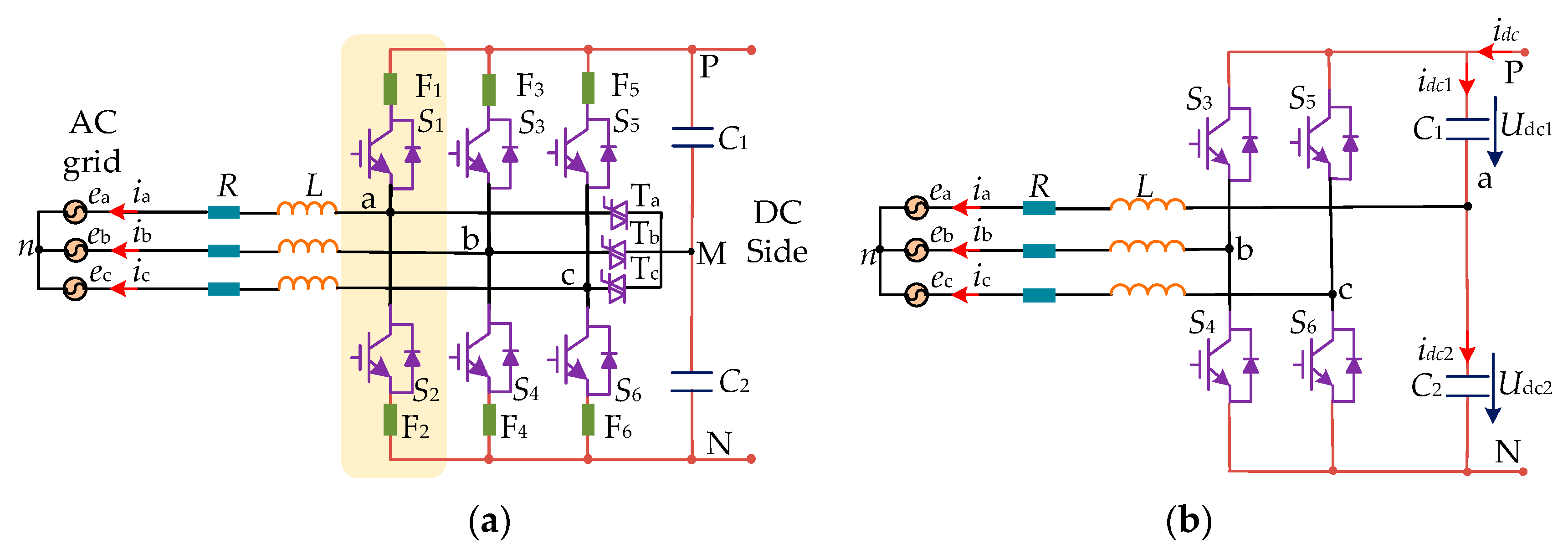
8]. Therefore, fast fuse devices can be connected in series with the switching devices to convert the short circuits to open circuits faults. The topology of nonredundant fault-tolerant BVSC is shown in
Figure 1a. The switch devices in the phase leg are IGBTs with antiparallel freewheeling diodes. The phase legs are also connected with the central point of the series capacitor by three bidirectional switches, which can be triode for alternating current (TRIAC) or IGBTs with single-phase diode rectifier. In normal operations, the bidirectional switches are in the open state. When short circuits or open circuits occur in one phase leg (such as phase a), a fast fuse device (F
1 or F
2) is opened, and the corresponding bidirectional switch T
a is conducted to achieve continuous operation [
9]. The reconstructed fault-tolerant BVSC is shown in
Figure 1b.
There are four switching devices in fault-tolerant BVSC (see
Figure 1b). The relationship between the output voltage vector and switching states of the converter is analyzed.
Si (
i =
b,
c) is defined as the switching state for fault-tolerant BVSC converter as,
The relationship between the output voltage and switching states of fault-tolerant BVSC can be expressed as [
14],
where
uan,
ubn,
ucn,
Udc1,
Udc2 are output voltages of the converter, and dc voltage of capacitor
C1,
C2, respectively.
The voltage components
uα,
uβ of the stationary coordinate system are obtained by Clark coordinate transformation. There are four switching states of (0, 0), (0, 1), (1, 0), (1, 1) in fault-tolerant BVSC. The voltages of TPFS structure in αβ stationary frame with phase a fault are shown in
Table 1.
The voltage vectors divide the vector space into four sectors, which are shown in
Figure 2. The amplitudes of the four basic voltage vectors are not equal. According to different conditions under
Udc1 =
Udc2,
Udc1 <
Udc2, and
Udc1 >
Udc2, the basic voltage vectors are different, shown in
Figure 3.
4. Model Predictive Control of Fault Tolerant BVSC
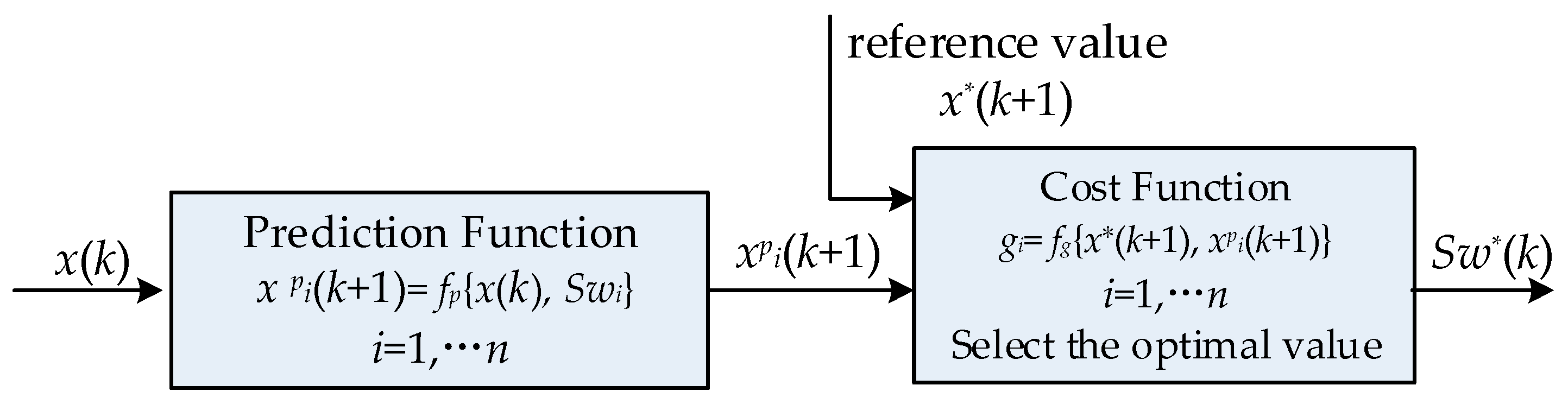
In recent years, MPC has been widely used in power electronics application fields such as motor drives, active filter, power regulation, and distributed generation. The main principle of MPC is shown in
Figure 4. The MPC system is designed to make the input variable
x be equal to the reference value
x*. In each sampling period, the optimal switching states of the power devices are solved online.
x(
k) is the input value of the
kth sampling period and is obtained by discretization of input variables. When the sampling frequency is high, the input variables in a sampling period can be considered as a constant. If the number of switching states
Sw is
n, the value of variable
xpi(
k) in the next period can be determined by function
xpi(
k)
= fp{
x(
k),
Swi},
i = 1,2
… n. Based on the working principle of the power converter, the predictive function
fp is established. The cost function
g need to be designed to select the optimal switching states
Sw*(
k) for the power converter, where
g = fg{
x*(
k + 1),
xpi(
k + 1)},
i = 1,2
… n.
x*(
k + 1) is the reference value of (
k + 1)th sampling instant. According to different control objectives, the cost function can be changed to achieve optimal performance. The output switching states of MPC can be applied to power devices directly. Therefore, the pulse width modulation (PMW) is not necessary.
For the selection of the optimal switching vector to realize model predictive control, a cost function
g is designed to compare all the predictive power values and select the voltage vector to minimize the cost function. The sum of the absolute error value between the predictive power, reference power, and dc-link voltage offset component is chosen as cost function,
where
Pref,
Qref are active power and reactive power reference value.
P(
k + 1),
Q(
k + 1) are power predictive values at the
tk+1 instant.
λ is the weighting coefficient, and Δ
Udc(
k + 1) is the predictive voltage offset at central point M of the dc-link.
In a digital implementation, there is usually a one-step delay between the selected voltage vector and the applied voltage vector, which has a significant impact on the dynamic and static performance of the system [
19]. To compensate this one-step delay in digital control, the cost function considering the tracking error at (
k + 2)th instant should be evaluated and minimized to select the best voltage vector, expressed as,
The first and second terms in the cost function penalize the power ripple. The third term is used to minimize the unbalanced dc-link capacitor voltages.
The predictive power and dc-link voltage offset at (
k + 2)th sampling period can be obtained from (
k + 1)th sampling instant and shown as,
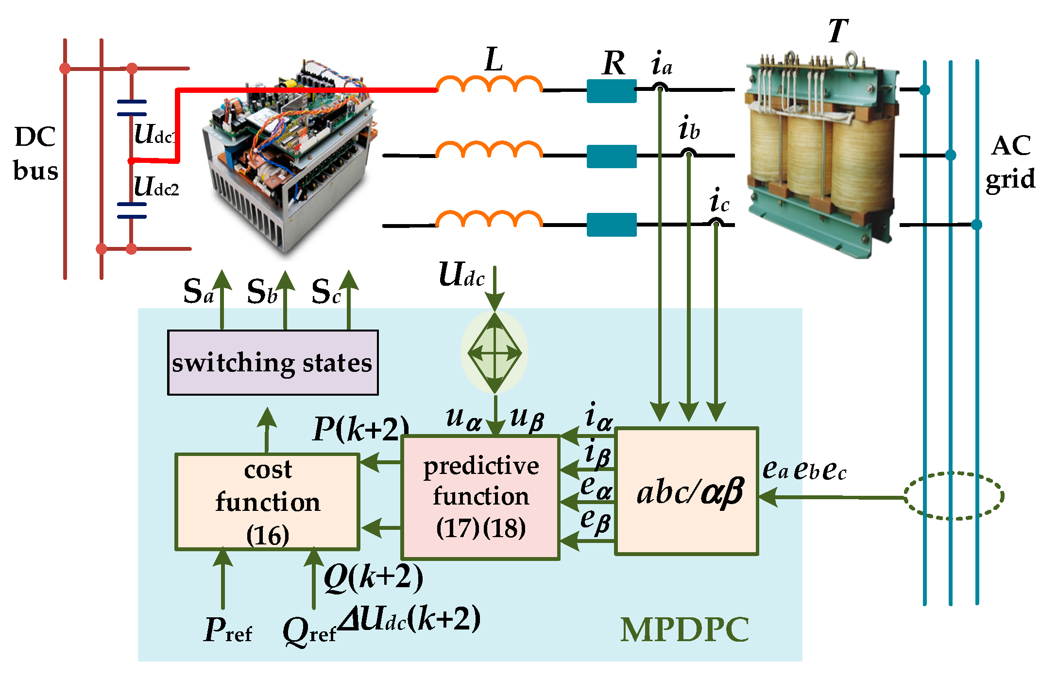
The MPDPC structure of fault-tolerant BVSC is shown in
Figure 5. The grid voltage and current
ea,
eb,
ec,
ia,
ib,
ic can be acquired by signal sampling circuits. After Clark transformation,
eα,
eβ,
iα,
iβ can be obtained. Predictive functions (14) and (15) calculate the power and dc-link offset voltage predictive values
P(
k + 2),
Q(
k + 2), Δ
Udc(
k + 2). The voltage vectors can be evaluated by the cost function (13). Then, the switching states, which minimizes the cost function, are selected and applied at
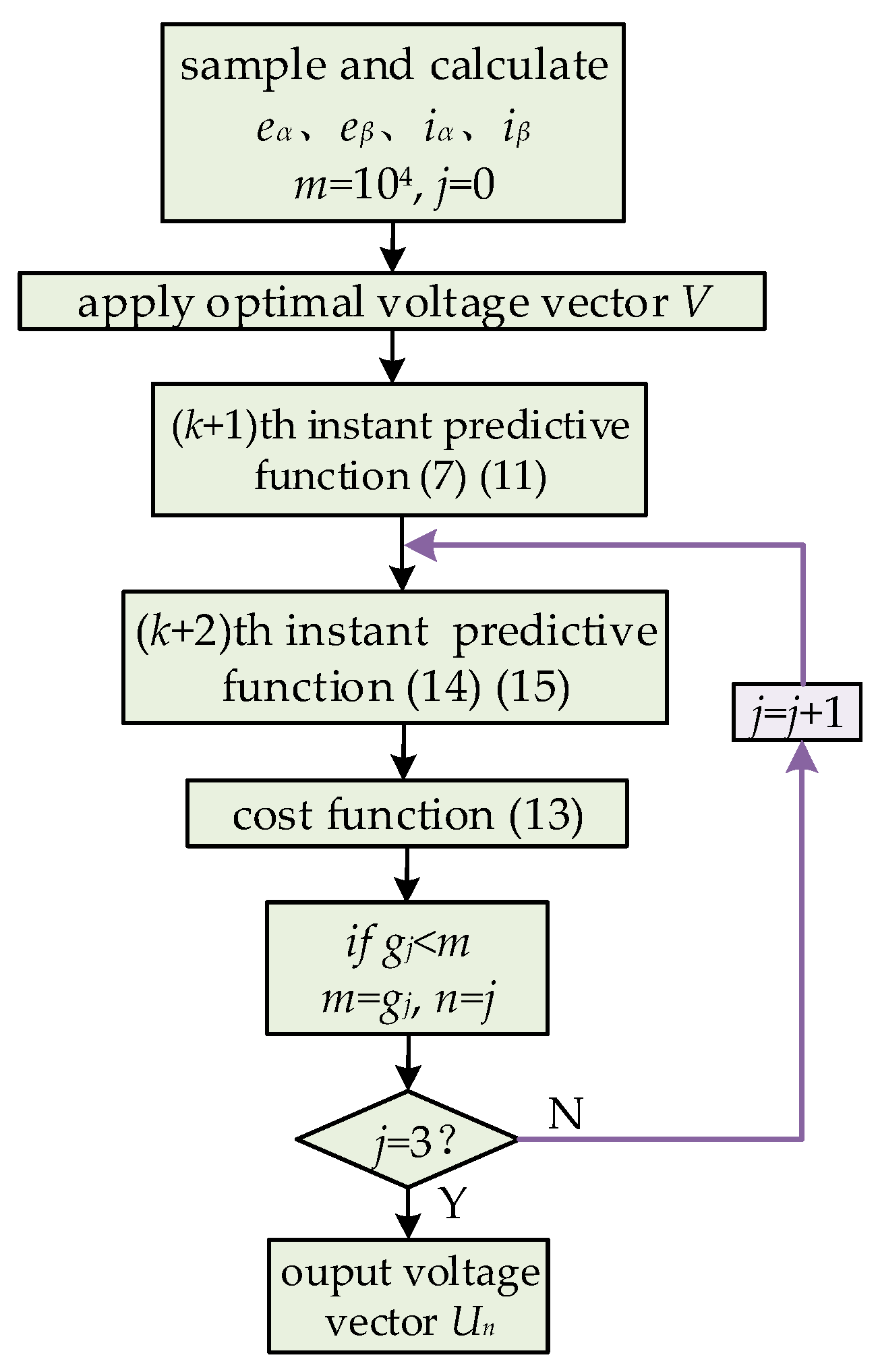
tk+1 instant to achieve direct power control. The flow chart of the MPDPC algorithm is shown in
Figure 6, where
m,
n,
j are variable parameters and
gj is the calculation result of the cost function.
5. Simulation Results
The traditional BVSC and fault-tolerant BVSC plans are simulated in MATLAB/Simulink (Mathworks, Natick, MA, US). The converters are built using the modules in SimPowerSystems. The comparison between the different topologies is conducted to verify the proposed control strategy of the fault-tolerant BVSC. The system parameters are shown in
Table 2.
Assuming the switch open circuits faults occur in phase a, the converter works with unit power factor. The reference active power is
Pref = 1000 W, and reactive power is
Qref = 0 Var.
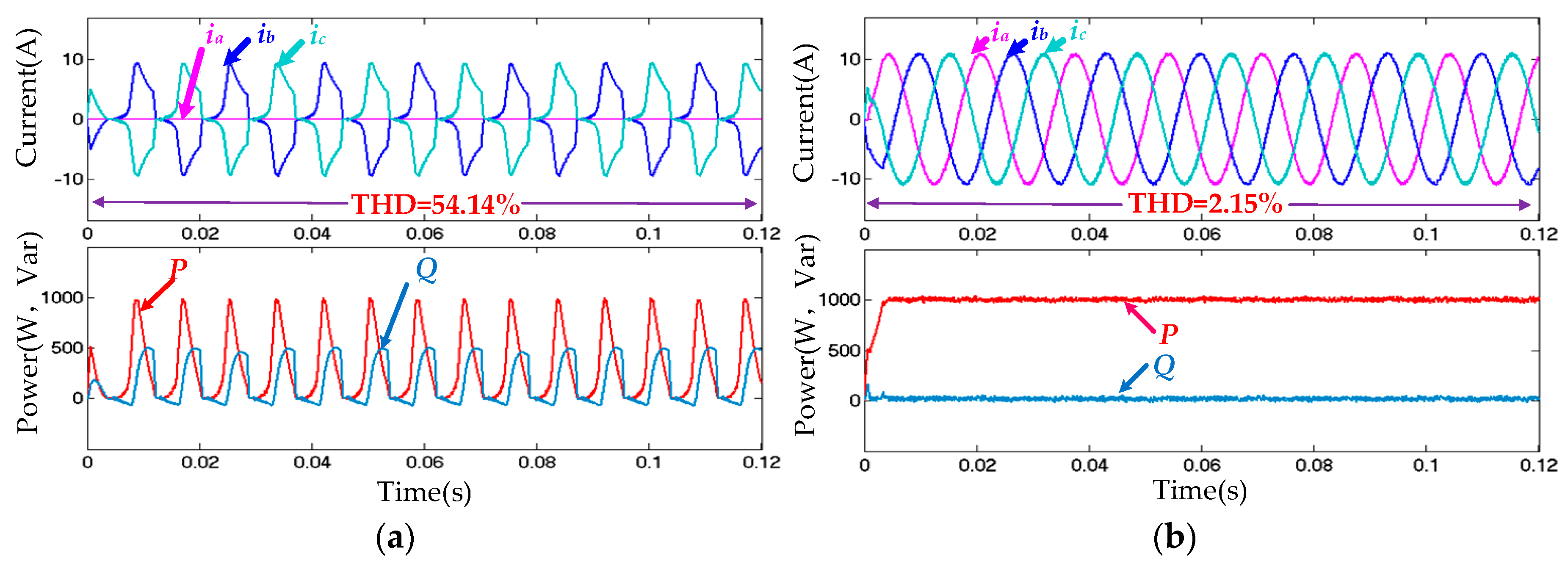
Figure 7 shows the three-phase grid-connected currents, active power, and reactive power in the inverter mode. It can be seen from
Figure 7a that when leg open circuit faults occur, the output current has serious distortion, and the current total harmonic distortion (THD) is 54.14%. Active power fluctuates from 0 to 1000 W, and reactive power changes between 0 and 400 Var, which shows that the BVSC cannot work normally in inverter mode. However, even if the bridge leg has a fault, the fault-tolerant converter can work continuously with the proposed MPDPC. The total harmonic distortion (THD) of grid current is 2.15% with better sinusoidal waveform, shown in
Figure 7b. Besides, the output power can track the reference power well and keep stable.
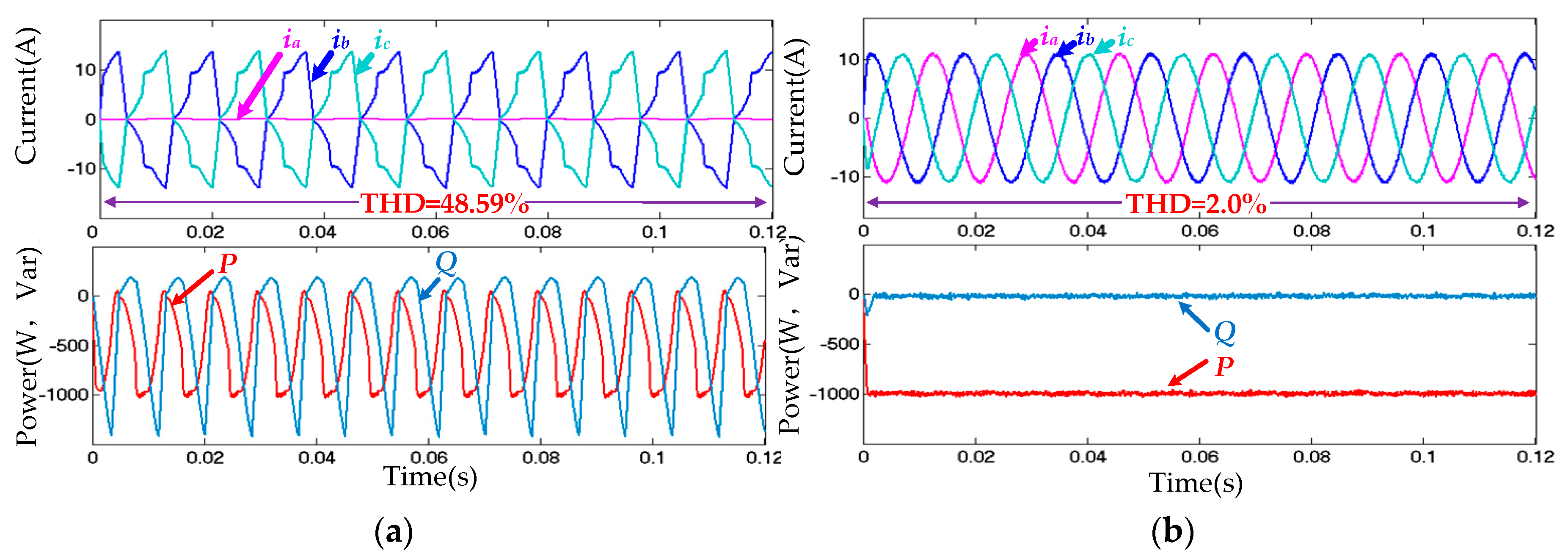
By changing the reference active power, the BVSC is switched from the inverter to rectifier mode. The switch open circuits faults occur in the phase a leg, where the reference active power is −1000 W and reactive power is 0.
Figure 8 shows grid-connected currents, output active power, and reactive power in the rectifier mode. The converter current and output power are distorted with traditional BVSC, which cannot ensure normal operation, as shown in
Figure 8a. On the contrary, by using the control of the proposed MPDPC for fault-tolerant BVSC, the grid connected currents are sinusoidal with 2.0% THD and the output power keeps constant, as shown in
Figure 8b.
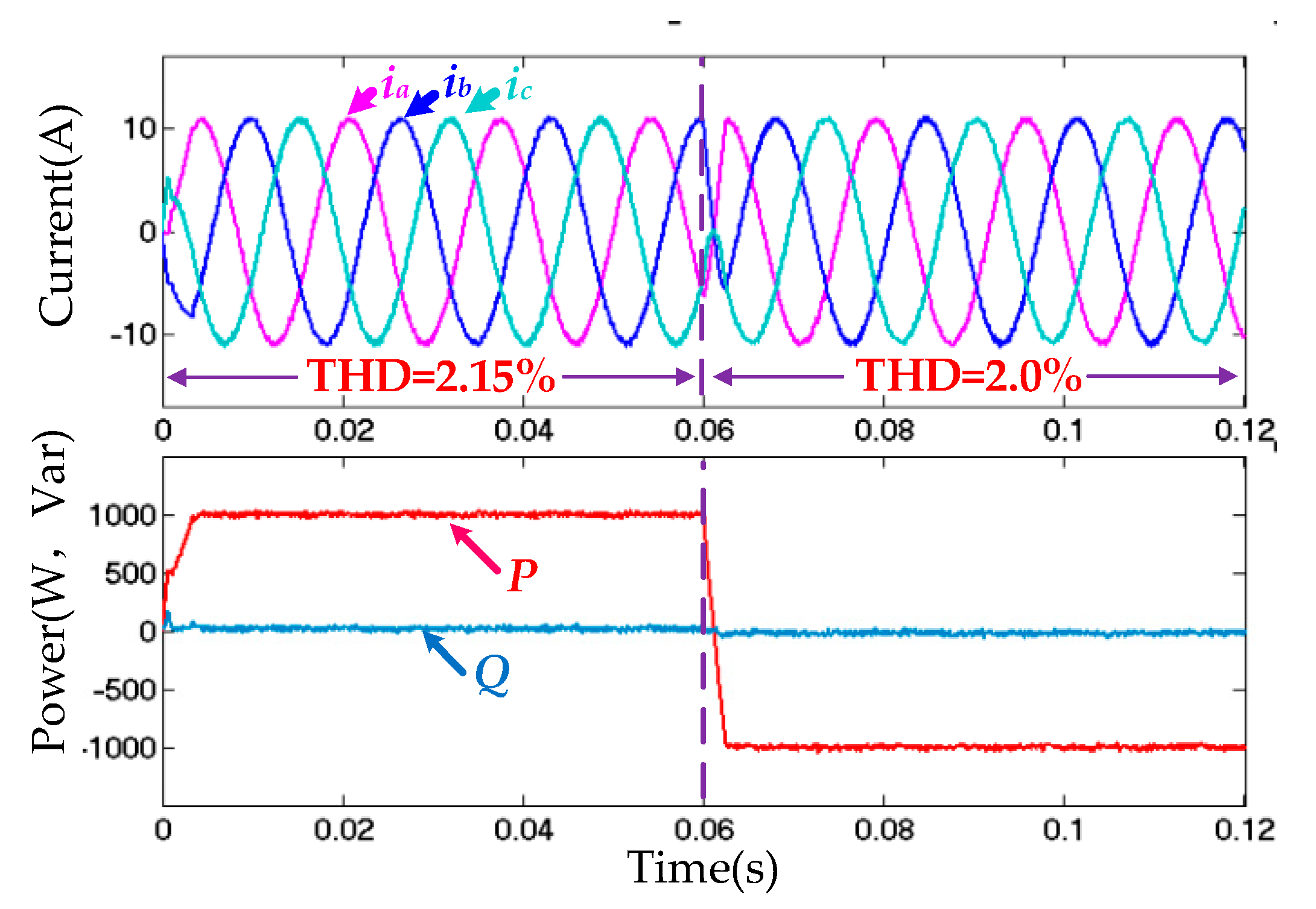
In order to verify the dynamic performance of the control strategy, a simulation is carried out as follows. The reference active power changes from 1000 W (inverter mode) to −1000 W (rectifier mode) at 0.06 s, and the simulation results are shown in
Figure 9. When the reference power changes, the fault-tolerant BVSC with MPDPC achieves a flexible smooth transition from the inverter to the rectifier mode, and it has good dynamic performance without surge peak transient impact.
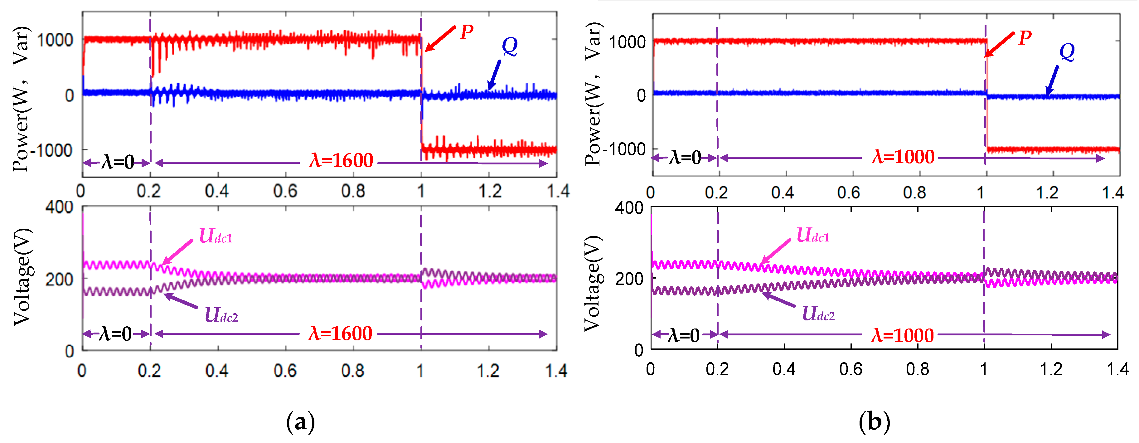
In (13), the weighting factor
λ can be adjusted to reduce the dc-link voltage offset. To investigate the influence of the weighting factor, comparisons with different
λ are conducted to show the effects on the dc-link capacitor voltage balance control performance. When
λ = 0, there is voltage unbalance in
Udc1 and
Udc2. At 0.2 s,
λ is changed to 1600 in
Figure 10a, and 1000 in
Figure 10b. The dc-link voltage unbalanced offsets are reduced due to the cost function (16). In
Figure 10a, the dc voltage regulation response with
λ = 1600 is faster than that with
λ = 1000 in
Figure 10b. However, for larger
λ value, the power ripple is much larger. As a result, there is a tradeoff for choosing
λ value considering both the dynamic performance and power ripple. At 1 s, the fault-tolerant BVSC is switched from the inverter mode to rectifier mode. DC-link capacitor voltage
Udc1,
Udc2 can also be controlled by using the designed method. The central point voltage of the dc-link split capacitors will be balanced in 0.2 s. The output active and reactive power of the converter change with the reference power with sinusoidal current waveforms, which validate the proposed control scheme.
6. Experimental Verification
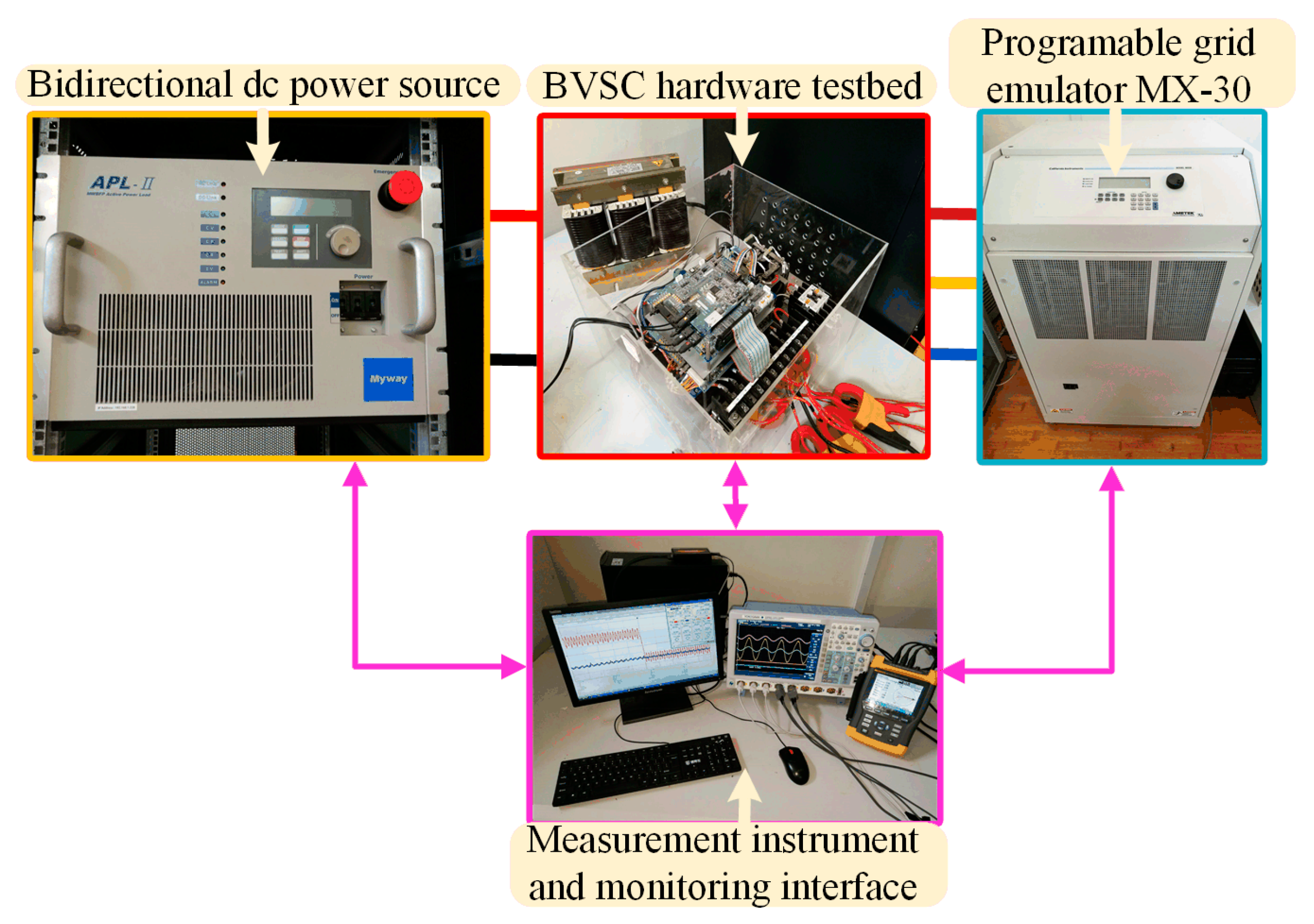
A hardware testbed consisting of a TI TMS320F28335 controller board and TPFS converter (shown in
Figure 11) was setup to verify the effectiveness of the proposed control scheme. The experimental parameters are shown in
Table 2, which are the same as those in the simulation. Experimental results were recorded by DLM4000 series (YOKOGAWA, Tokyo, Japan) mixed signal oscilloscope, FLUKE 435B power quality analyzer (Fluke, Everett, WA, US). Bidirectional dc power source APL (Myway, Kanagawa, Japan) has been used to emulate the dc side. The MX-30 ac programmable power supply (Ametek, Berwyn, IL, US) emulates the ac grid. The experimental tests have been realized on both BVSC and fault-tolerant BVSC in different work modes.
Figure 12 and
Figure 13 show the steady-state waveforms of traditional BVSC and proposed MPDPC for the fault-tolerant BVSC in inverter mode with leg faults in phase a. The converter works with the unit power factor. The reference active power is
Pref = 1000 W, and reactive power is
Qref = 0 Var. The following waveforms include three-phase voltage and current, active power, and reactive power.
Figure 14 and
Figure 15 show experimental results in rectifier mode, and the reference active power is −1000 W with unit power factor. In
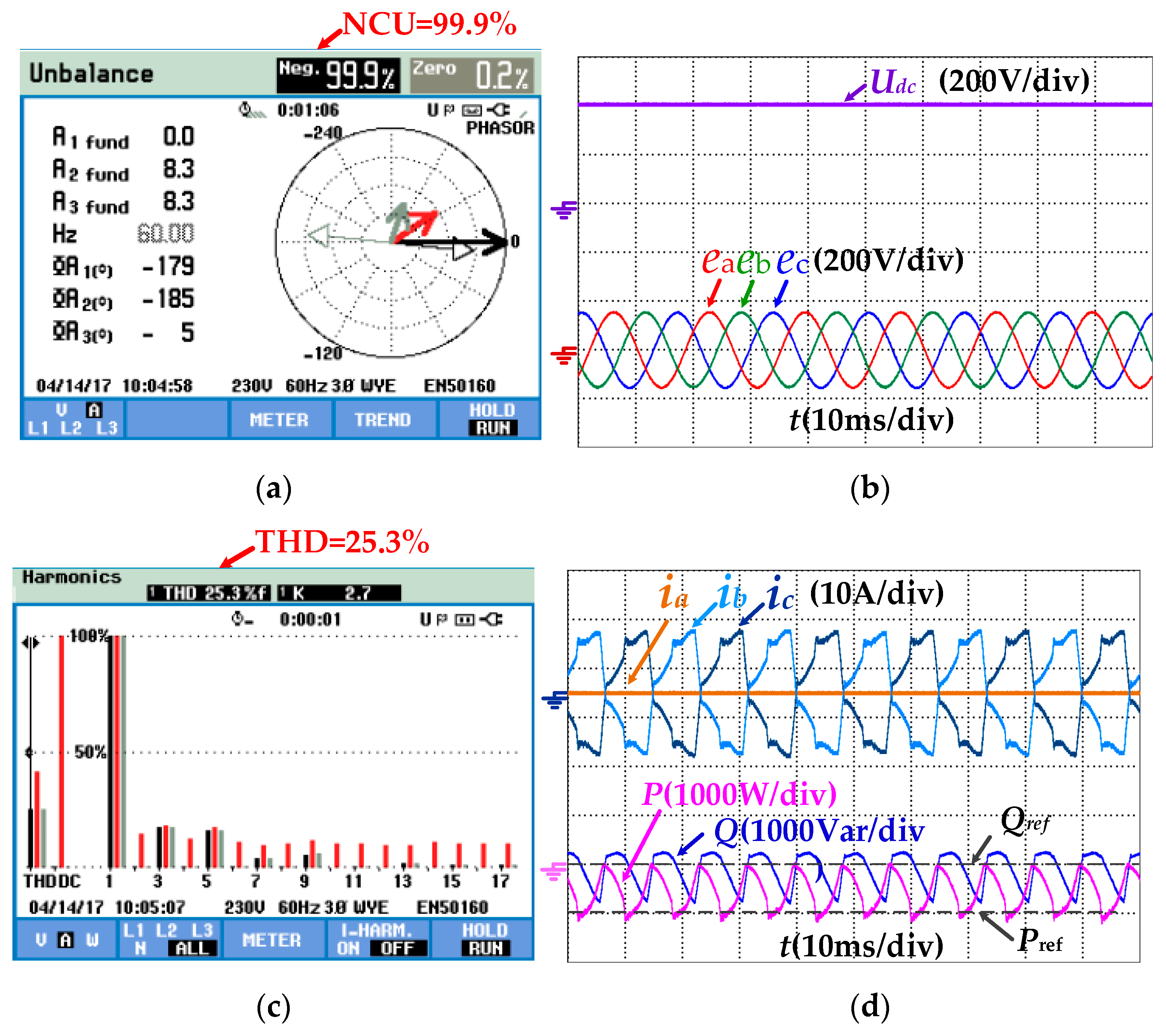
Figure 12 and
Figure 14, it can be seen from steady-state waveforms that, when there are phase leg faults in traditional BVSC, the grid currents are highly distorted, and output power is unstable.
The power quality analyzer Fluke 435II (Fluke, Everett, WA, USA) was used to measure the current THD and negative current unbalance (NCU). In the inverter mode, the current THD is up to 44.6%, and the negative current unbalance of three-phase currents reach to 99.8%, as shown in
Figure 12. In the rectifier mode, the current THD is up to 25.3%, and the negative current unbalance of three-phase currents reaches 99.9%, as shown in
Figure 14. The experimental results show that when a leg fault of BVSC occurs, the BVSC cannot realize effective control.
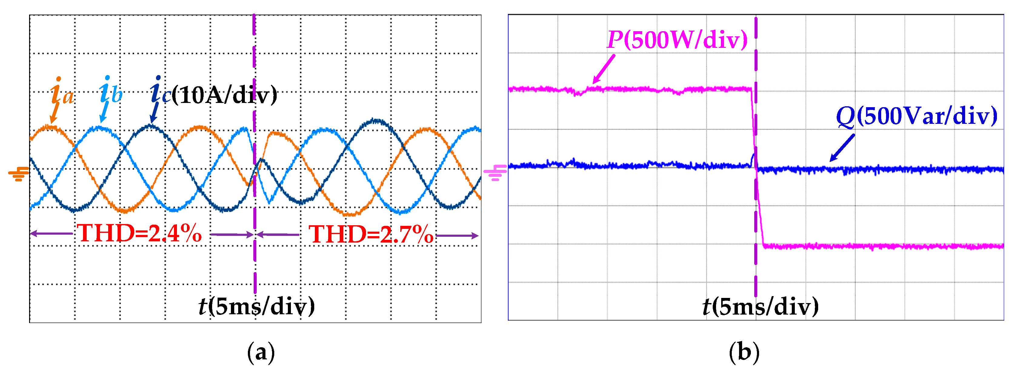
However,
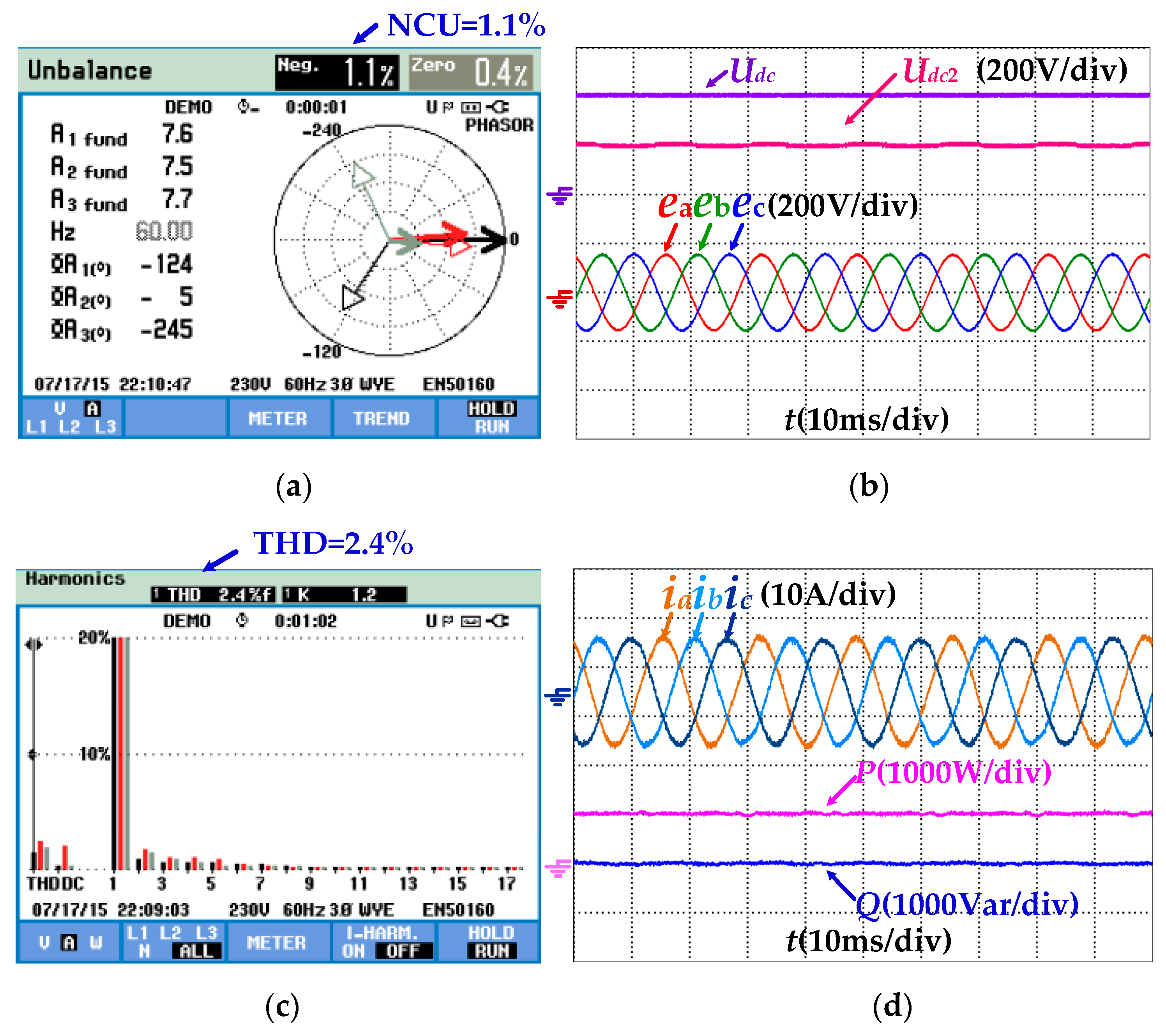
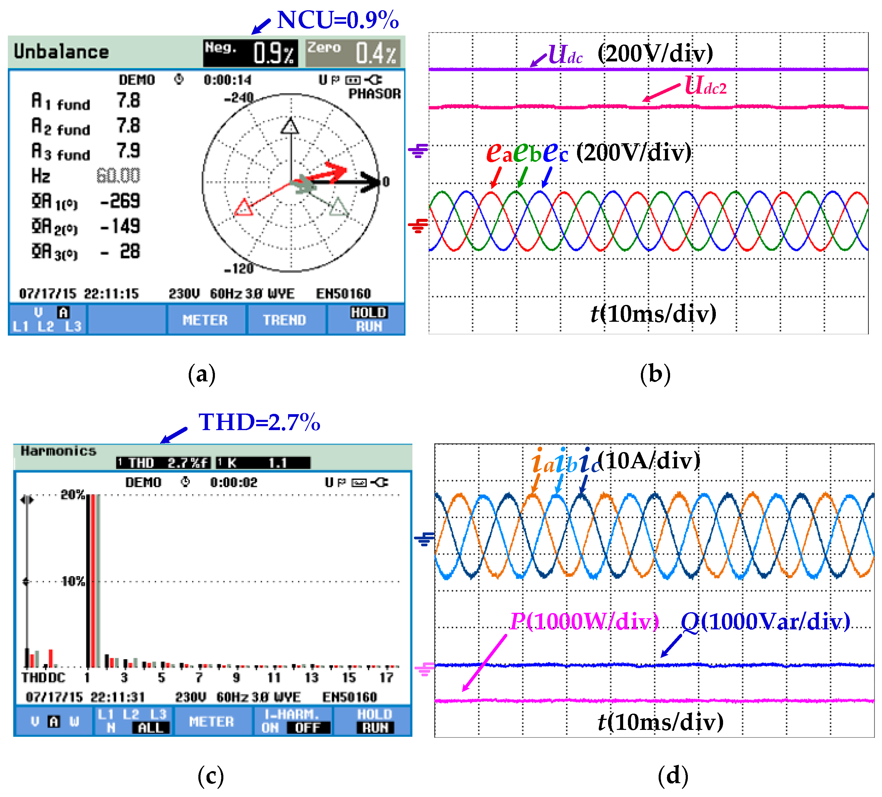
Figure 13 and
Figure 15 show that the converter can work properly by using the proposed MPDPC for fault-tolerant BVSC, even if the phase leg has a fault. The current THD decreases to 2.4% in the inverter mode and 2.7% in the rectifier mode. The negative current unbalance is reduced to 1.1% in the inverter and 0.9% in the rectifier mode. The dc-link capacitor voltage is controlled and stable. The current THD and negative current unbalance are shown in
Table 3.
In order to verify the dynamic performance of the control strategy, the experiment was carried out as follows: the reference active power steps from the 1000 W (inverter mode) to −1000 W (rectifier mode) at 0.05 s. The experimental results are shown in
Figure 16. It shows that when the reference active power of the proposed MPDPC changes, the output power is regulated to the new value after about 0.2 ms without the current surge, power fluctuations, and other transient impacts. Three phase currents are sinusoidal, and the flexible seamless switching between inverter and rectifier mode can be realized. The output power of the fault-tolerant converter keeps stable with the reference value.
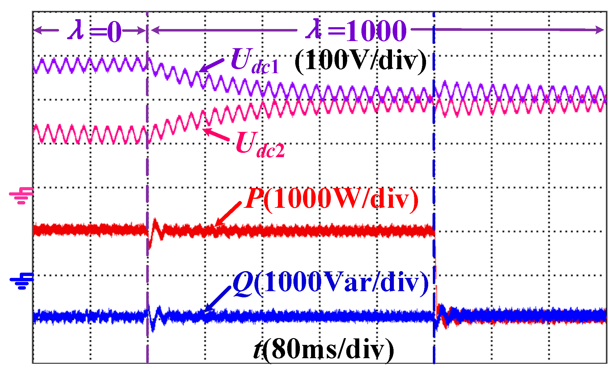
To verify the effectiveness of dc-link split capacitor voltage balance design, comparisons with different
λ in both rectifier mode and inverter mode are carried out to show the dynamic response of the dc-link voltage balance control. In
Figure 17, before 0.24 s, the fault-tolerant BVSC works in inverter mode with
λ = 0. The dc-link capacitor voltage
Udc1,
Udc2 are not balanced. In this condition,
Udc1 is larger than the rating value. The capacitor
C1 works in over-voltage conditions. The power loss and the temperature of the capacitor
C1 will increase, and the capacitance value of
C1 will decrease. This will reduce the lifetime of the capacitor
C1, which is prone to cause the failure of the electrolytic capacitor for over-voltage operation. For long-term operation under over-voltage conditions, the deteriorating performance of the electrolytic capacitor will become the destructive fault. To avoid this problem, the predictive function and cost function with the dc-link split capacitor voltage balance control is designed. At 0.24 s, the weighting factor is set to
λ = 1000. The experimental results show that with the additional term in the cost function, the dc-link capacitor voltage is regulated to be balanced. At 0.48 s, the fault-tolerant BVSC is switched from the inverter mode to rectifier mode. During this transition, the dc-link capacitor voltage can be kept balanced with the fast transient process. The experimental results verify that the proposed control scheme can keep dc-link capacitor voltage balanced with good static and dynamic response, which also reduce the risk of the electrolytic capacitor failure caused by the dc-link unbalanced over-voltage.
According to the experimental results, when phase leg faults occur, the proposed MPDPC for fault-tolerant BVSC has better performance compared with the traditional plan, which ensures continuous and reliable operation of the converter with leg faults.
7. Conclusions
In this paper, a model predictive direct power control (MPDPC) method is proposed for nonredundant, fault-tolerant BVSC with phase leg open circuits faults. When the faulty leg has been isolated by the connection switch, the BVSC is reconstructed as a fault-tolerant TPFS topology. Based on the working principle analysis, a power predictive model of fault-tolerant BVSC in αβ coordinates is designed, and space voltage vectors with unbalanced dc-link capacitor voltage are analyzed after topology reconfiguration. The finite states model predictive direct power control method of fault-tolerant BVSC is investigated for continuous operation, even if the BVSC has leg open circuits faults. The cost function considering the elimination of power ripples and dc-link split voltage balance control is used to select the optimal voltage vector, which achieves flexible smooth switching between inverter and rectifier mode with direct power control. With the proposed scheme, the dc voltage offset component can also be minimized to keep the central point of the dc-link voltage offset suppression. The proposed method makes the utilization of the MPC advantageous for combining different control objectives together without using PWM modulation, phase locked loop, or double loop control. The flexible switching between the inverter and the rectifier mode of the fault-tolerant BVSC is achieved by changing the reference active power. Finally, the effectiveness of the proposed control strategy to improve the bidirectional power conversion reliability is verified by both simulation and experiments.


