Low Voltage Ride-through Scheme of the PMSG Wind Power System Based on Coordinated Instantaneous Active Power Control

Ministry of Education Key Laboratory of Modern Power System Simulation Control and Green Power Technology, Northeast Dianli University, Jilin 132012, China
*
Author to whom correspondence should be addressed.
Energies 2017, 10(7), 995; https://doi.org/10.3390/en10070995
Submission received: 7 April 2017
/
Revised: 7 July 2017
/
Accepted: 10 July 2017
/
Published: 14 July 2017
(This article belongs to the Section F: Electrical Engineering)
Abstract
:Fast control DC-link voltage is the key to enhance Low-Voltage Ride-Through (LVRT) for the Permanent Magnet Synchronous Generator (PMSG). When grid voltage dips deeply, by the constraint of the capacity of the grid-side converter and reactive power support by the grid-code required, the active power capacity of the grid-side converter will be reduced. Therefore, it cannot stabilize the DC-link voltage relying solely on the grid-side converter. This paper proposes an improved control strategy to combine generator-side and grid-side converter active power. Reactive power support and negative sequence feed-forward compensation are also considered in the paper. The effectiveness of the control strategy is verified by both simulation and the experimental results.
1. Introduction
Among various renewable energy sources, wind power has been considered as one of the most rapidly growing energy sources. The total installed wind power capacity worldwide reached 432.6 GW at the end of 2015 [1]. The penetration level of wind power in the power system has significantly increased, and the influence of wind plants in power system operation becomes more important. For these reasons, utility operators have gradually updated their grid connection requirements (GCRs) for generators [2,3,4]. One of the serious issues is Low-Voltage Ride-Through (LVRT), namely the wind power system is required to remain connected when a grid dip occurs, contributing to keeping the network voltage and frequency stable by delivering active and reactive power to the grid with a specific profile depending on the grid voltage dip depth.
Variable speed is the dominant technology for wind turbines in the current market [5,6]. Either a Double-Fed Induction Generator (DFIG) with a Partial-rating power converter [7,8] or a direct-driver Permanent Magnet Synchronous Generator (PMSG) with a full-rating converter is employed. In comparison with DFIG, the PMSG-based wind power system is more attractive because of its simple structure, wide operating range, high power density and complete decoupling from the grid [9,10].
At a grid fault, the output power of PMSG decrease instantaneously and results in the swell of the DC-link voltage, which seriously impacts the stable operation of the PMSG system, even leading to being off-grid in some situations. Stable DC-link voltage is the key to enhance LVRT for PMSG systems. Several methods for LVRT fulfillment are found in the literature, and they can be classified into two groups: add auxiliary equipment and improve the control method. (1) Adding auxiliary equipment: The combined control of a DC circuit breaking resistor, the turbine blade angle and converters was proposed in [11,12]. The work in [13,14] proposed the use of energy storage systems to store mismatched energy. Additionally, the Dynamic Voltage Restorer (DVR) was used to compensate the symmetry, and asymmetrical grid voltage fault was proposed in [15]. A similar Static synchronous Compensator (STATCOM) was used to provide reactive power support to improve the grid-voltage in [16]. In [17], the Series Dynamic Breaking Resistors (SDBRS) were suggested to consume the excess active power during grid voltage dips. The auxiliary grid-side converter paralleled with the grid-side converter to enhance LVRT capability and improve power quality was proposed in [18]. However, the use of these devices will increase the system cost and multi-device coordinated control complexity.
An improved control scheme seems to be a more attractive method when considering cost. Mismatched energy is temporarily stored in the moment of inertia of the wind turbine, not needing auxiliary devices. The work in [19] suggested reducing the generator-side converter output power in proportion to the grid voltage reduction. The DC-link voltage control by the generator-side converter instead of grid-side converter was explored in [20,21,22], so that it is easier to keep the DC-link voltage constant by increasing the generator speed during grid voltage sags. However, subject to the nonlinear relationship between the generator speed and DC-link voltage, the Proportional-Integral (PI) controller does not have good performance, and a complexity controller, such as the fuzzy control method [22], is developed. In the literature [23], the DC-link voltage is regulated by the grid-side converter under normal conditions, instead of being controlled by the generator-side converter during grid-voltage sags. In [24], a unified DC-link current controller was developed for Current Source Converter (CSC)-based wind power systems.
This paper proposed a new LVRT control strategy for the PMSG-based wind power system. The grid-side converter and generator-side converter are both intended to regulate the DC-link voltage when the grid voltage dips deeply. Reactive power support and asymmetrical voltage dips also are considered in the paper.
The rest of the paper is organized as follows: Section 2 details the basic characteristics of PMSG and the traditional control methods; the proposed controlled strategy is given in Section 3. The simulation results and experimental results are found in Section 4 and Section 5, respectively. Finally, brief conclusions are formulated in Section 6.
2. Modeling of the PMSG-Based Wind Power System
The study of PMSG-based wind power systems and the conventional control diagram are shown in Figure 1. The PMSG system consists of the wind turbine, a PMSG and a fully-rated back-to-back PWM (Pulse-Width Modulation) converter. The back-to-back PWM converter consists of a generator-side converter, DC-link capacity and a grid-side converter.
For the generator side, in the rotor flux orientation rotating frame, the electrical equations of the PMSG are expressed as in [7]:
where and are the d-and q-axis stator voltage, and are the d-axis and q-axis stator inductance (for the generator with surface-mounted permanent magnets, d-axis and q-axis inductance are the same ()), and are the d-axis and q-axis stator currents, is the electrical angular speed, is the magnetic flux and represents stator resistance.
For the grid side, in the grid voltage orientation rotating frame, the electrical equations of the grid-side converter are:
where and are the d-axis and q-axis grid voltage, and are the d- and q-axis grid currents, and are the d- and q-axis grid-side converter output voltages, and represent the grid-side resistance and inductance and is the grid angular frequency.
Assuming that the loss of the converter is neglected, generator side input power and grid-side output power can be expressed as [8]:
where and are DC currents of the generator- and grid-side converter.
Applying Kirchhoff’s current law to a DC-link capacitor node, it follows that ; hence:
According to Equation (5), when the system is operating in the steady state, the input power of the generator-side is equal to the output power of the grid-side and satisfies the equation: and keeps constant. When the grid suffers a fault, the grid voltage reduction will induce the active power delivered to the grid to decrease, and it will be less than the output power for the generator. The mismatched power occurs and induces the DC-link voltage increase.
The conventional control strategy is also provided in Figure 1. The function of the generator-side converter is to extract maximum power by regulating the torque-producing current . The maximum power tracking (MPPT) method based curve is used in this paper [21].
The maximum power of the wind turbine can be calculated with the maximum power coefficient and the optimal Tip-Speed Ration (TSR) as:
where is the air density, is the blade swept area, is the turbine rotor angular speed, is the maximum power coefficient, and is the radius of the blade.
with direct-driven PMSG, and considering power loss, the generator power reference is given by:
is not easy to calculate; for simplicity, in this paper, only considers generator power loss ,grid power loss and frictional loss, and other losses are treated as a constant, . can be expressed as:
where F is the friction factor.
To decouple the q-axis and d-axis current control in the rotor flux orientation rotating frame, from Equation (1), the feed forward compensation terms are introduced as:
For the grid-side converter, the control object is to keep the DC-link voltage constant by controlling the grid-side d-axis current and providing the q-axis reactive current.
When the d-axis of the grid-side synchronous rotating frame is aligned with the grid-voltage vector, . Additionally, according to Equation (2), the forward decoupled compensation terms in the grid-side current control loops are given as:
According to Equation (5), DC-link voltage depends on the grid-side and generator-side active power. Normally, grid-side d-axis current is utilized to regulate DC-link voltage, while is treated as disturbance. In order to quickly control the DC-link voltage, it can calculate the generator-side active current () and feed an equal amount of current to the grid-side d-axis current [25,26], so as to make
However, when the grid voltage drops, the maximum grid-side converter active power is reduced in proportion to the grid voltage reduction, for the upper limit of the converter current is a constant. The conventional control strategy regulating the DC-link voltage relies solely on the grid-side converter. When the grid voltage drops deeply, the power capacity of the grid-side converter will decrease, and will reach the upper limit of the grid-side converter. The grid-side converter will lose the control ability of the DC-link voltage, and the DC-link voltage will continue to rise if not quickly consumed or will reduce the input power from the generator side.
3. Proposed Control Method
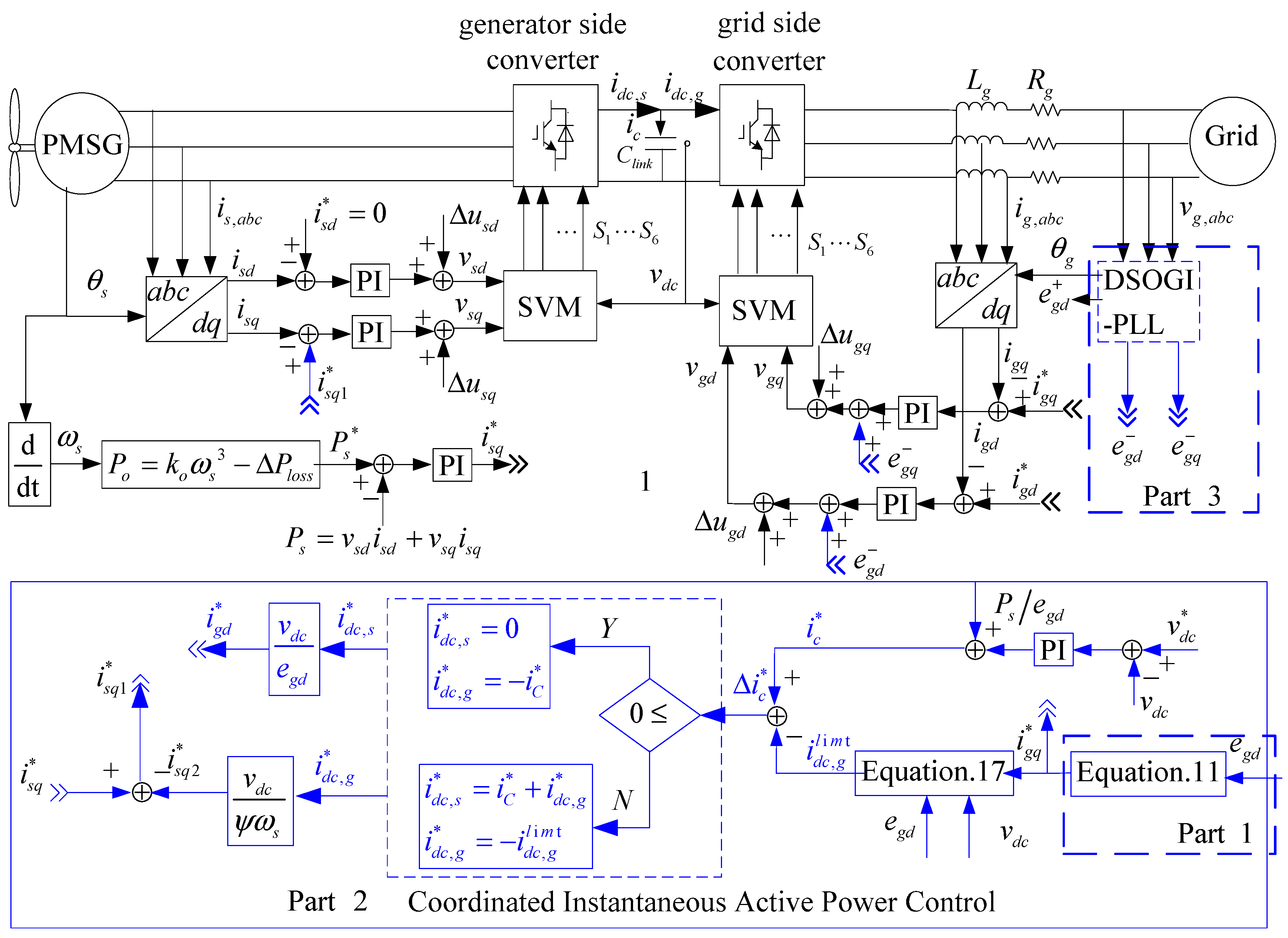
The proposed control block diagram for the system is shown in Figure 2. Compared with the conventional control strategy in Figure 1, the improved Parts are highlighted in blue lines, and it can be divided into three Parts. Part 1: Reactive power support according to E.ON grid-code requirements; Part 2: DC-link voltage control based on coordinated active power; Part 3: negative sequence voltage feed-forward. They are detailed as follows, respectively.
3.1. Reactive Power Support
According to E.ON’s grid connection requirements [4], when voltage has fallen more than 10%, the wind power system has to provide 2% of the rated current for each percent of the voltage dip. A reactive power output of at least 100% of rated current must be possible if necessary, as shown in Figure 3.
Therefore, the reactive current injected to the grid can be the formula below:
Ignoring the phase-locked loop dynamic characteristics, the d-axis component of grid voltage ed is equal to the amplitude of grid voltage, so , and UN is the rated voltage. As described above, this can, according Equation (11), set the grid side reactive current reference .
3.2. Coordinated Active Power Control
According to Formula (5), the DC current of the grid-side, generator-side converters and the DC-link capacitance current satisfy the equation:
Supposing , and respectively represent the DC current reference value of the generator-side, the grid-side current and DC-link capacitance current that contribute to the DC-link voltage control, so:
Note that , and are control variables and do not represent the real DC-link current. As for the conventional control strategy in Figure 1, the generator-side converter does not respond to the DC-link voltage regulator. Therefore, , and ; is the output of the Proportional-Integral (PI) of the DC-link voltage regulator.
In the Figure 2, is divided into two parts: and . The DC-link regulator both uses the generator-side converter and grid-side converter to stabilize the DC-link voltage.
According to the upper limit of grid-side DC current , there are two ways to set the current reference:
- (1)
- . If the DC-link-regulated current is within the grid-side converter active power capability, set , so . The DC-link regulator uses only the grid-side converter to control the DC-link voltage, and the generator-side converter still works in MPPT mode, and it avoids wind energy losses at normal operating conditions.
- (2)
- . The excessive portion of will be transferred to the generator-side converter to reduce the input active power from the generator. Namely, , and and are translated into the active current references and using Formulas (14) and (15):
is the new reference of the grid-side d-axis current controller, and is the new reference of the generator-side q-axis current controller.
When the grid voltage sags, the reactive current provided is given higher priority than the active power injected to the grid. Thereby, the active current is restricted by:
The short time permissible over the current for the converter is usually 1.1-times the rated current [27], namely . According to Equation (6), is set 1 p.u. when the grid voltage dips below 0.5 p.u. Additionally, it is easy to calculate from Equation (11).
When the d-axis is orientated on the grid voltage vector, can be obtained. Therefore, the upper limit of grid-side DC current is given:
According to Formula (17), automatically reduces with grid voltage and reactive power current. In other words, the active power current capacity decreases because of the grid-voltage dips and reactive power support requirement. When the grid voltage dips deeply, thereby along with voltage dips. The DC-link regulator will choose the second current reference set and reduce the generator torque current automatically. The grid-side converter and generator-side converter are both used to control the DC-link voltage. When the grid voltage recovers gradually, increases, and will equate to or be smaller than sometimes. The regulator chooses the first current set. The grid-side converter will regain the DC-link voltage control capability absolutely, and then, the generator-side converter operates in the maximum wind energy capture and does not intend to regulate the DC-link voltage. It does not need an outside decision to change the control mode, and all of the transitions are managed automatically.
During grid sag periods, the mismatched power between the mechanical powers acquired by the wind turbine and the electrical power output of the PMSG will be produced. Additionally, the generator speed will gradually increase, the mismatched energy stored as kinetic energy in the moment of inertia. The typical inertia time constant of a megawatt wind turbine is around 4–6 s. Considering the short time voltage dip, as describe in the E.ON grid connection requirements [4], the generator speed will be only slightly increased and does not affect the safe operation of the PMSG system.
Compared with the conventional control strategy, the difference between the conventional and the proposed control strategy in this paper is the DC-link voltage control. Assuming that the decoupling is done by the controller, according to Figure 2, the DC-link voltage control block diagram can be simplified as shown in Figure 4, below.
As Figure 4 shows a dual loop control system, the current inner control parameters should be designed first. When the system open loop transfer function is known, it is convenient to tune the parameters by the tuning control tool provided by the MATLAB software. According to Figure 3, the system parameters in Table 1 and the given frequency domain requirements, the bandwidth = 350 dB and the phase margin = 60. The PI2 and PI3 control parameters designed by the PID tuning control tool are given in Table 2.
Although the DC-link voltage control outer loop interconnect with both the grid-side d-axis current control loop and the generator-side converter q-axis current control loop, the two currents are not really connected to the DC-link voltage outer loop at the same time. Only the grid-side d-axis current references reach the upper limit; the generator-side q-axis current attend to the DC-link voltage control. Then, the outer DC-link PI controller design needs to consider the grid-side inner loop or generator-side inner loop, respectively, and obtains the parameters with the trade-off of the two different inner loops. Fortunately, the dynamic characteristics of the grid-side inner loop and generator-side inner loop are similar if carefully tuned with the PI controller parameters; then it is not difficult to get the DC-link outer loop control parameters. Given that the frequency domain index approximates the bandwidth = 50 dB and the phase margin = 50°, the DC-link voltage PI control parameters are obtained and shown in Table 1. The Bode plots and step response curves of the simplified systems with different inner current loops are shown in Figure 5.
3.3. Negative Sequence Voltage Feed-Forward
At present, the grid connection requirements do not take into account the asymmetric voltage sag. However, single phase short circuit fault is the most common failure in power system; it is significant to the development of the control method under asymmetric voltage. For asymmetric voltage drop conditions, grid-side voltage will contain a negative sequence component. The grid-side state-space model in the negative synchronous frame [21] is:
where , are the negative-sequence d-axis grid current, , are negative-sequence d-axis voltage at the grid-side converter terminals and , are the negative-sequence d-axis, q-axis grid voltages. There are two control methods usually used in asymmetry voltage conditions, which are the vector current controller feed-forward of the negative-sequence grid voltage, for which the abbreviation is VCCF (Vector Current Controller Feed-forward) in [28], and Dual Vector Current Controllers (DVCCs) [29].
Additionally, negative-sequence voltage feed-forward is adopted in the paper because of its simplicity. The control block diagram of VCCF is shown in Figure 6. The current controller is implemented in the positive-sequence frame, while the negative-sequence grid voltage is the feed-forward component added to the current control output. The grid-side converter will output the same negative-sequence voltage as the grid voltage, . According to Equation (18), when the system is stable, only positive-sequence currents flow to the grid.
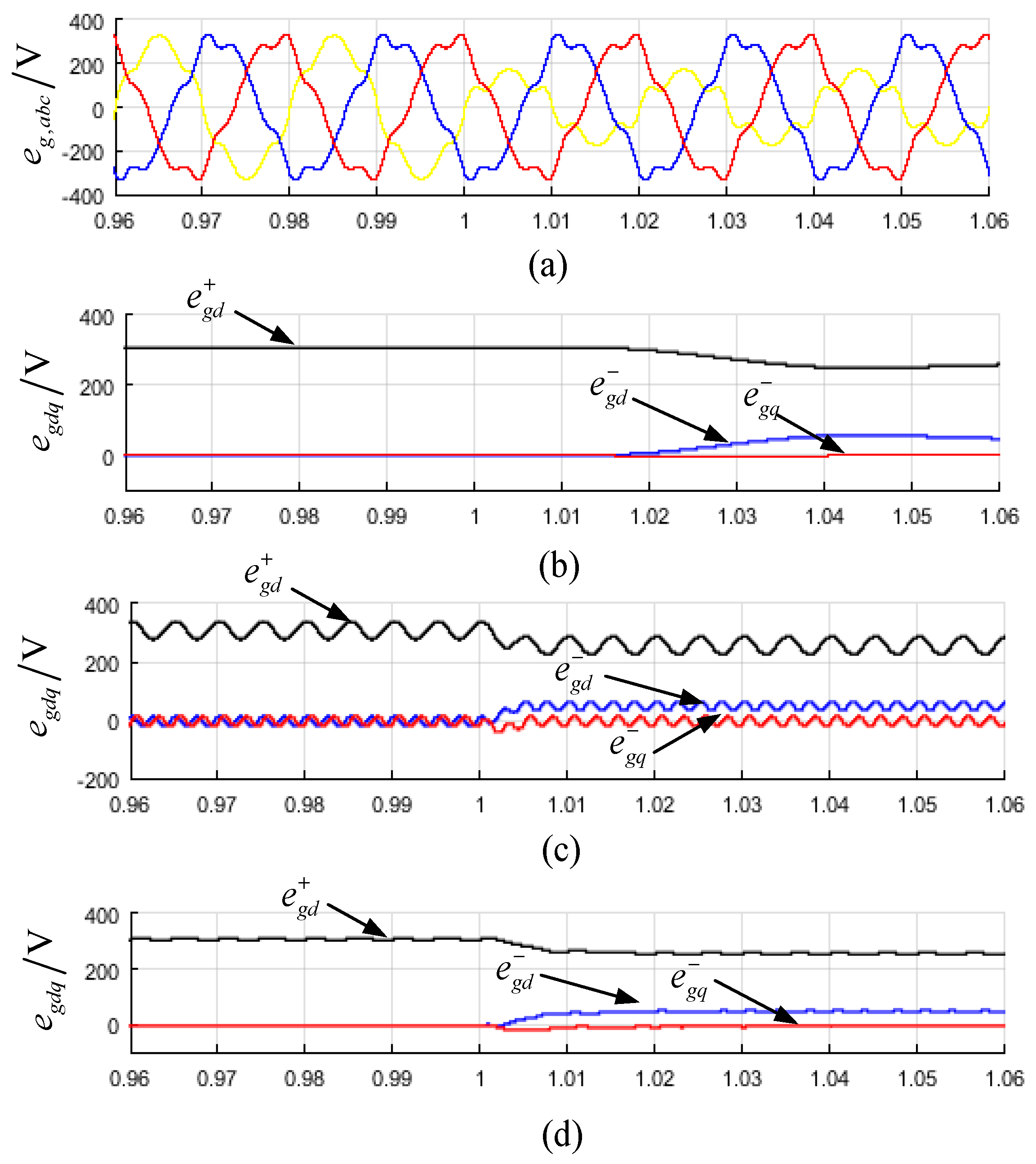
Fast and accurate online detection of the positive and negative phase-sequence is critical for VCCF. The authors have compared three sequence separation methods, such as the Low-Pass Filter (LPF) [28], Delayed Signal Cancellation (DSC) [28,29,30] and the Dual Second-Order Generalized Integrator Frequency-Locked Loop (DSOGI-FLL) [31]. Additionally, the simulation results of these methods are presented in Figure 7. The test voltage signals are given in Equation (19), which are three-phase sinusoidal signals included the fifth and seventh harmonic components.
Additionally, at t = 1 s, there is a phase voltage dip of 50%. Taking into consideration the performance of both steady accuracy and transient response, DSOGI-FLL seems to be a better method than the others, and it was used in the paper.
The block diagram of DSOGI-FLL is presented in Figure 8. As shown in Figure 8, DSOGI-FLL works in an frame, with two SOGIs being used to compute the symmetrical components; one for and another for . The two SOGIs are arranged in parallel to provide the input signals to the positive/negative-sequence calculation block (PNSC), which implements the transformations given by Equation (20).
4. Simulations’ Verification
To verify the validity of the proposed control strategy, the 1.5-MW wind power system described in Table 2 was modeled in MATLAB/Simulink. Symmetrical voltage and unsymmetrical voltage dip simulation cases are discussed below.
4.1. Case A: Deep Symmetrical Voltage Dip
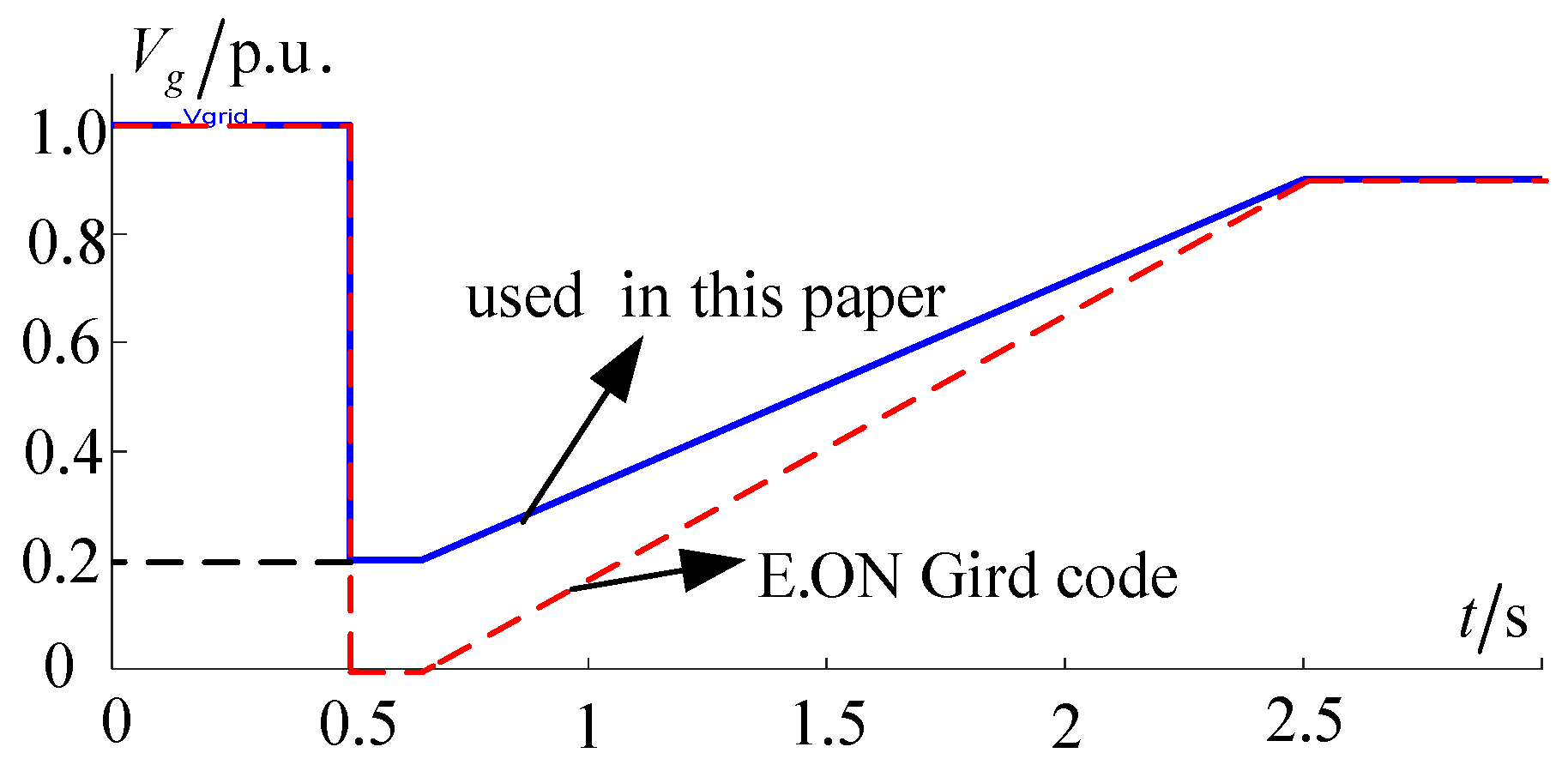
According to the E.ON grid code, wind farms must withstand voltage drops down to 0% of the nominal voltage for durations up to 150 ms, as the red curve shown in Figure 9. Depending on the network and wind farm configuration, it does not necessarily lead to zero voltages at the wind generator terminal side. A relatively simple calculation indicates that the corresponding voltage dip at lower voltage levels, near the WT terminals, is likely to be somewhat above 15% [32]. For that reason, the grid-voltage dip curve used in the paper is the blue curve in Figure 9; namely, at 0.5 s, the grid-voltage dips to 15% and lasts for 150 ms, and then, the voltage slope recovered to 90% until 2.5 s. The lowest grid voltage was set to 15% instead of 0%.
The work in [19] proposed that the generator-side torque current reduces in proportion to the grid voltage reduction, which can be expressed as:
where is the current reference for the MPPT module.
However, the method is an open-loop control. The reduced active power of the generator side may be too much or too little. As it reduced too little, DC-link voltage may result in over voltage for the mismatched power between the grid-side converter and the generator-side converter. Otherwise, the generator rotor speed may rise faster for the mismatched torque power between the wind turbine capture and generator-side converter, and more captured wind power will be lost.
For contrast, the coordinated active power control method proposed in the paper and the control method proposed in [19] are both simulated. The simulation results are shown in Figure 10 and Figure 11, respectively. The initial wind speed was set to 12 m/s; the initial rotor speed is the optimal speed of 1.1 p.u., and the wind turbine captured power is 0.73 p.u.
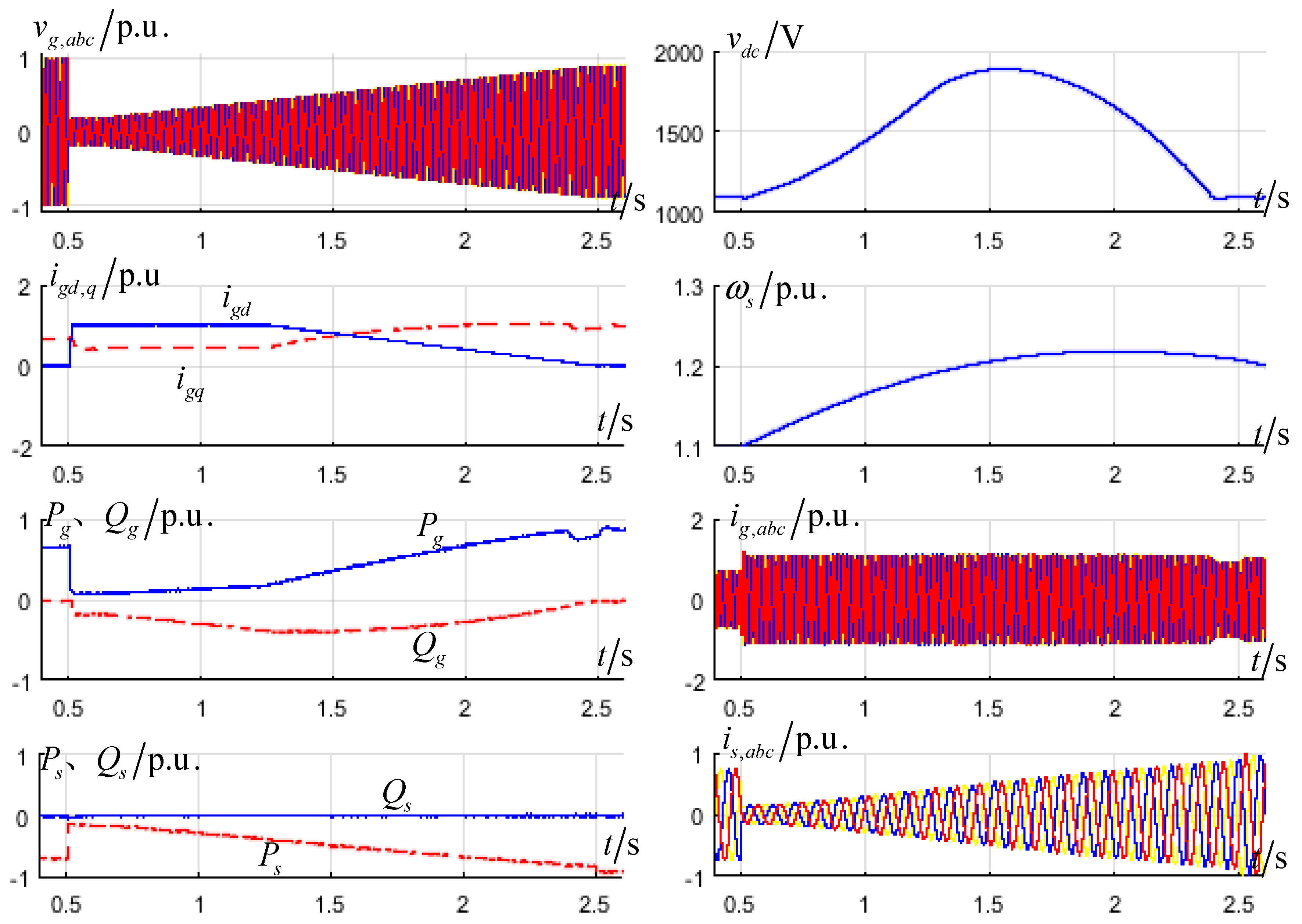
Figure 10 presents the simulation result used in the Equation (21) control method. At t = 0.5 s, the grid voltage dips to 15% p.u.; the grid-side reactive current reaches 1 p.u. according to the grid-connected requirement; the grid-side active current also reaches the upper limit of 0.4583 p.u., and the corresponding active power is 0.09 p.u. According to the control method used in Formula (21), the generator-side active current reduce to 0.15-times the initial current; it is 0.11 p.u., calculated by Equation (21). The input active power from the generator-side converter is greater than the output active power of the grid-side converter. The DC-link voltage still rises until 1.6 s. The peak of DC-link voltage is 1900 V, and it may destroy the DC-link capacitance in real physical equipment. With grid-voltage restored and the ability of the grid-side output active power increased, after 1.6 s, the generator-side active power is lower than the grid-side power, and the DC-link voltage decreases. However, the grid-side active current is still in the upper limit until 2.3 s. The upper limit of the grid-side active current changes because the reactive current required is changed with the voltage rise. At 0.23 s, the DC-link voltage controller exits saturation, and the DC-link voltage recovers to 1100 V. Because of the reduced generator-side input power, the rotor speed rises, and the peak value is 1.22 p.u. at 2.5 s; the grid voltage recovers to 0.9 p.u; the generator-side does not reduce the active power and changes to the maximum wind power capture mode.
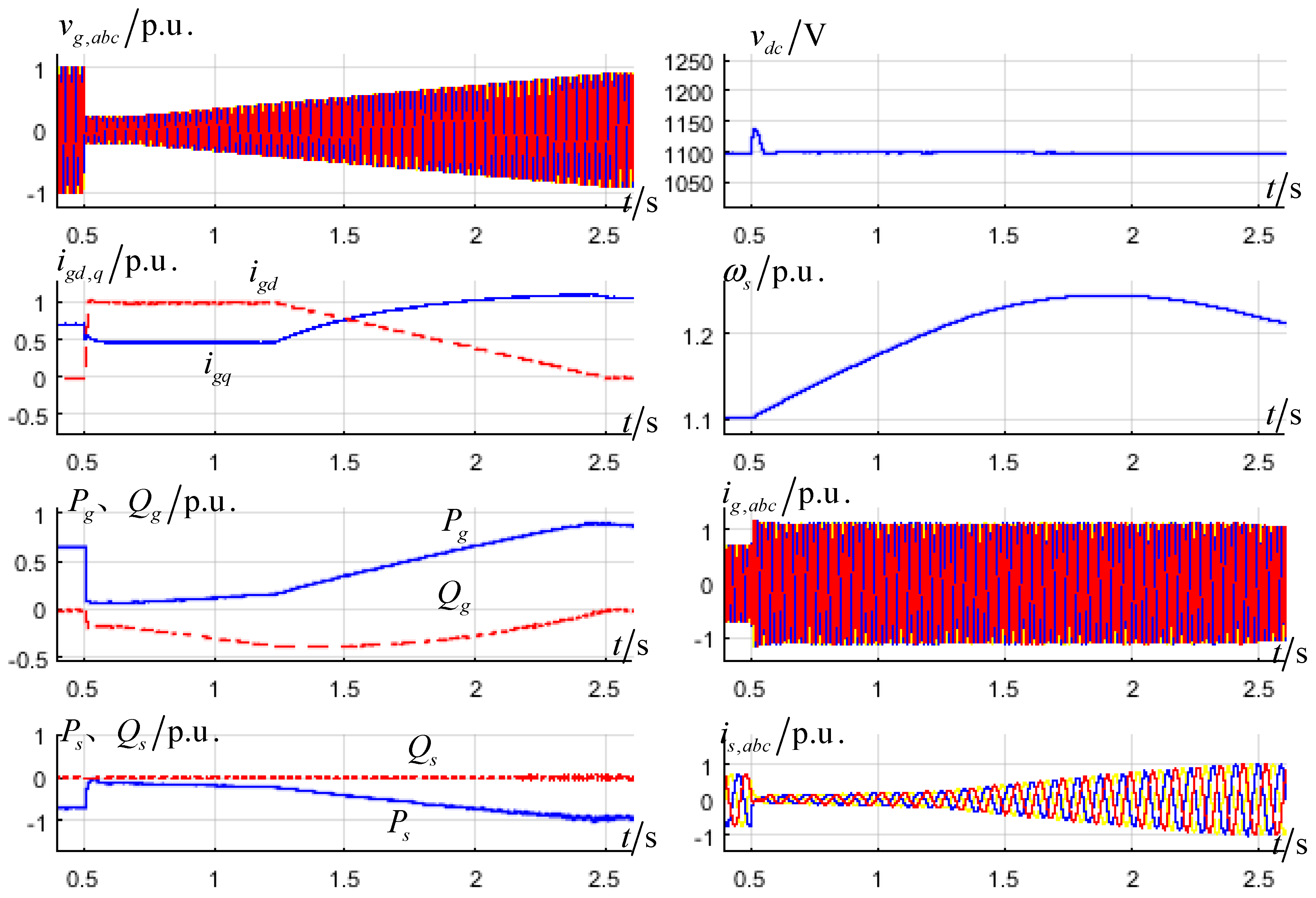
Figure 11 shows the simulation result of the proposed control method in this paper. Due to the reason of the active power coordination control, both generator-side q-axis and grid-side d-axis current are used to regulate the DC-link voltage. At 0.5 s, the grid-side d-axis current also reaches the upper limit, and the q-axis changes to 1 p.u. because of the reactive support; but the generator-side current decreases due to the active power coordination control algorithm; it reduces more active power compared to the method in Formula (21) (see curve in Figure 11 ). DC-link voltage slightly rises and recovers 1100 V soon; the peak value is only 1140 V. With the grid voltage recovering gradually, the ability of the grid-side converter output active power is increased. Additionally, the reduced input active power of the generator-side converter is decrease. At t = 2.4 s, the generator-side converter exits controlling the DC-link voltage and automatically transfers to the maximum wind power capture mode. Because the generator-side converter input active power reduced more than using Formula (21), the peak value of the rotor speed is 1.25 p.u., greater than the 1.22 p.u. in Figure 9. Both of the peak rotor speeds are within a safe range. The safe rotor speed range of the MW wind power system is 0.67 p.u.–1.33 p.u. [33].
Compared with the control method in [19], the proposed method has two advantages. First, it realizes closed loop DC-link voltage control when the grid voltage dips deep and avoids the occurrence of the over voltage risk. Second, transitions between normal and fault conditions are achieved automatically.
4.2. Case b: Deep Asymmetrical Voltage Dip
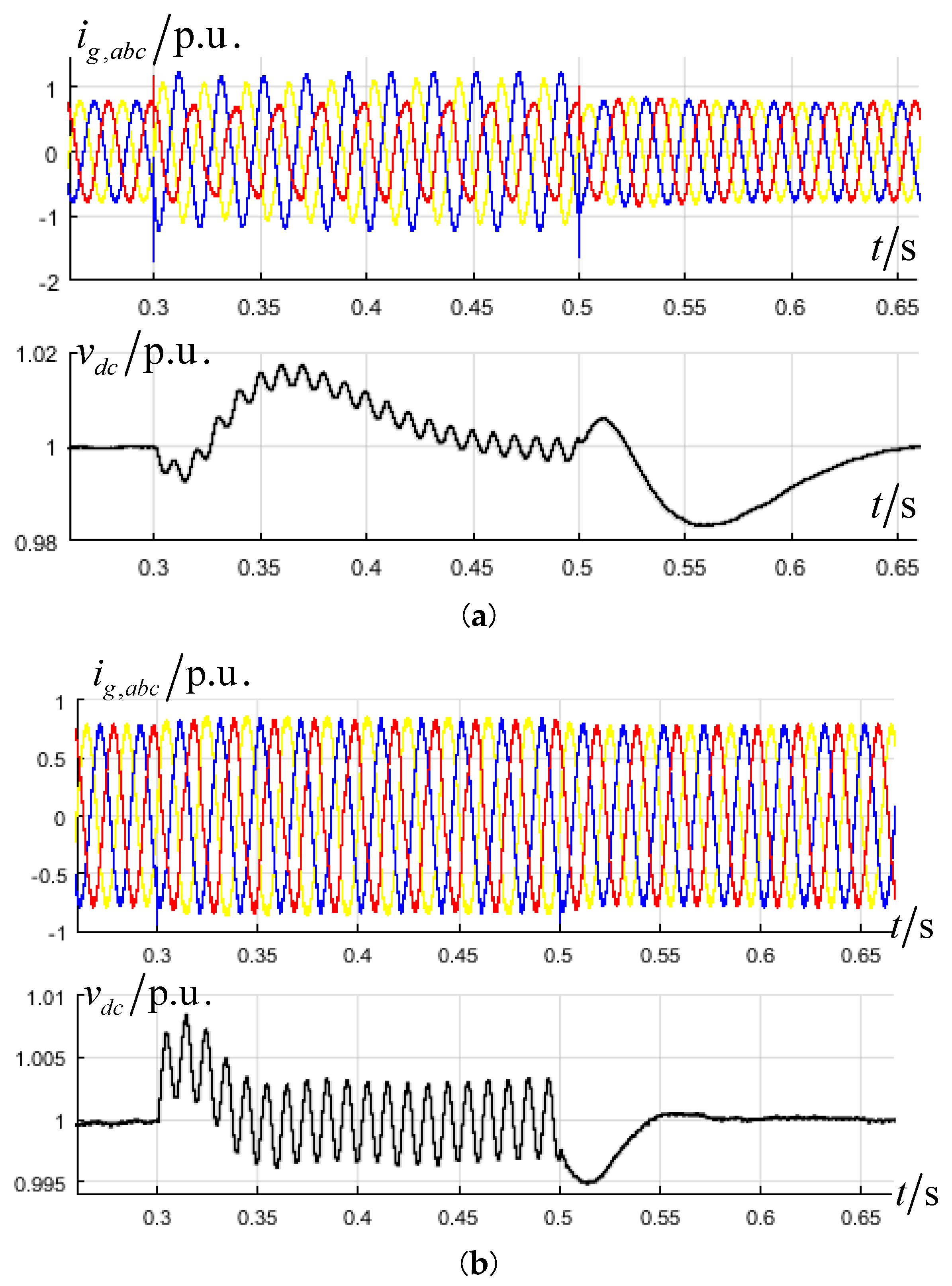
The design of asymmetric voltage dip case: at 0.3 s, Phase b suffers a 50% drop, and this lasts 200 ms. Compared with negative voltage feed forward control or not, the simulation waveforms are shown in Figure 12 below.
Seen from Figure 12, the grid currents are obviously asymmetric without adding negative voltage feed forward, as shown in Figure 12a, and the grid current markedly improved and approximately kept the symmetry with adding negative voltage feed forward, as shown in Figure 12b.
Both in Figure 12a,b DC-link voltage occurs twice for grid frequency oscillations during asymmetrical conditions and in Figure 12b, the oscillations are larger. This is because the system works with symmetric a, b, c currents and asymmetric a, b, c phase voltages, so the grid-side active power contains positive-sequence and negative-sequence components. The generator-side active power contains only the positive-sequence component.
5. Experimental Results
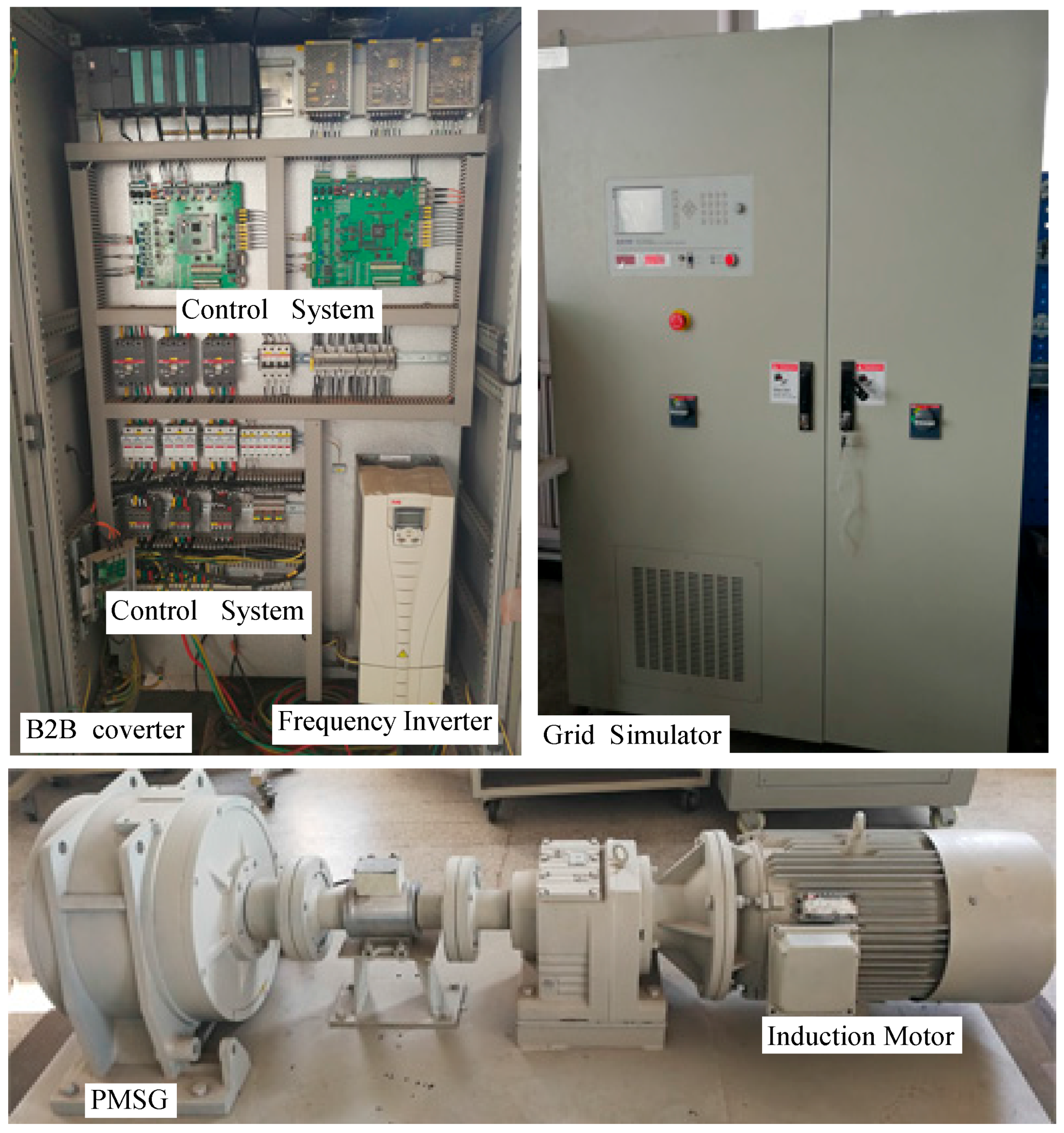
To demonstrate the validity of the proposed algorithm, the experiment has been carried out for a 10-kW PMSG wind power system (CORONA Science &Technology Company, Beijing, China). The induction motor controlled by the ABB ACS550 frequency inverter is used as a wind turbine simulator. The grid simulator used for sag generation was the PVS7030T (PARWA Technology Company, Shenzhen, China). The parameters of the experimental system are shown in Table 3. The experimental setup is shown in Figure 13.
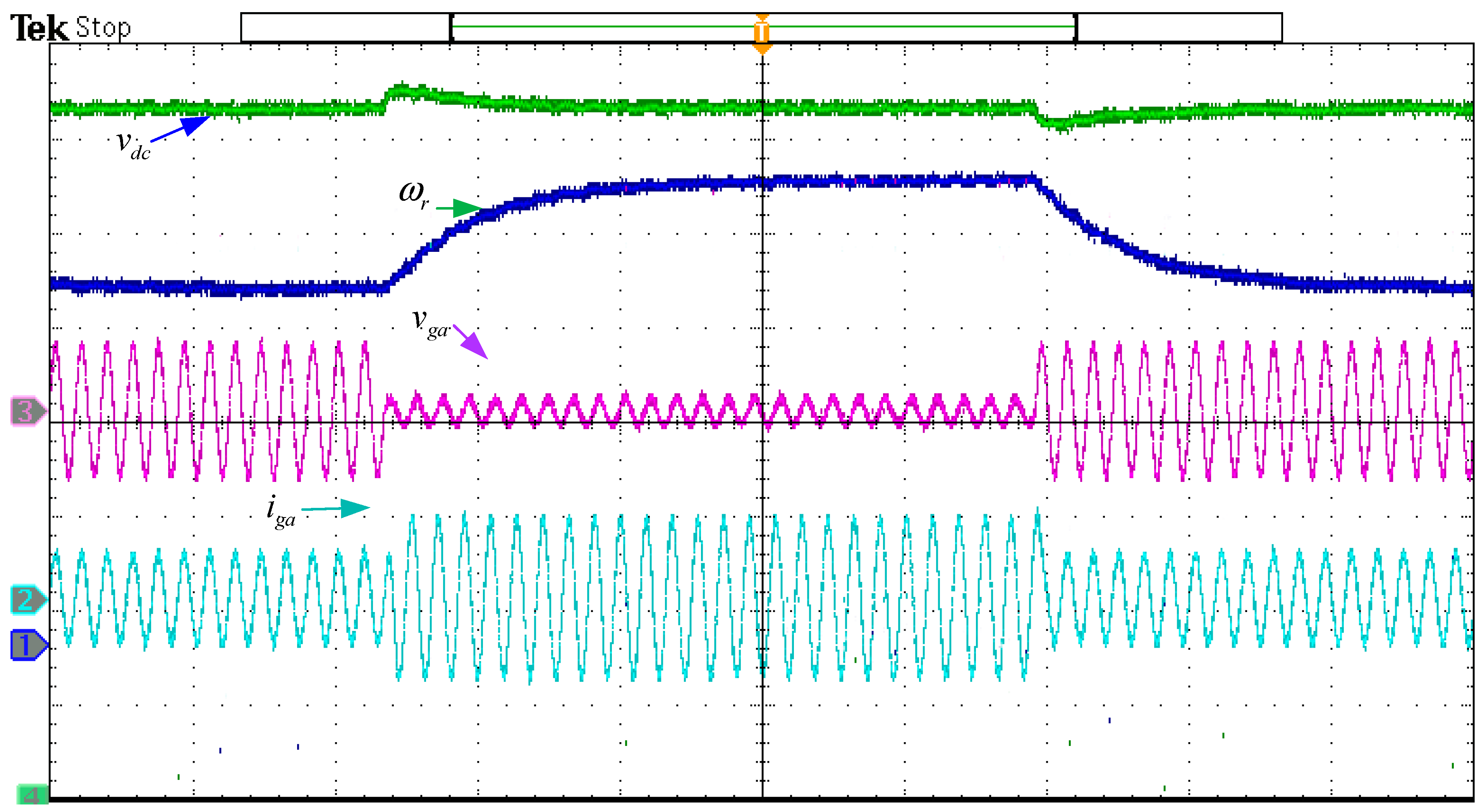
In accordance with the simulation cases, symmetrical and unsymmetrical voltage dips are tested. Because of the low rotational inertia, the experiment system cannot withstand long time voltage sags. Therefore, the design scenario is changed, that is: grid voltage drops 80%, lasting 500 ms. The experimental results are shown in Figure 14.
Seen from Figure 14, when grid-voltage dips, DC-link voltage rises about 1235 V and recovers to 1200 V. The grid current increases, but mainly is the reactive component. By the influence of the generator-side active power decrease, the rotor speed continues the PMSG increase during the grid-voltage sag period. When grid voltage recovers, the system automatically transits to the maximum wind energy capture mode. Mechanical speed decreases and is gradually restored to the optimal speed.
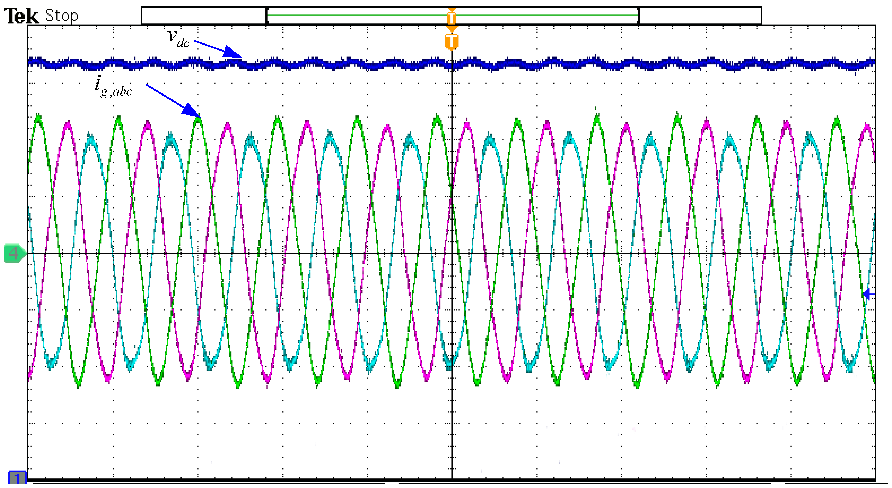
Similar to the simulation Scenario, phase a grid voltage is set to drop to 50; the experimental results with and without negative voltage feed forward control are shown in Figure 15 and Figure 16, respectively.
The experimental results in Figure 15 and Figure 16 are similar to the simulation results in Figure 12. DC-link voltage appears twice in the grid-voltage frequency fluctuations under the asymmetry conditions, with or without negative voltage feed forward. The grid-side current maintains symmetry when adding negative feed-forward voltage.
6. Conclusions
In this paper, an improved LVRT coordinated control strategy for the PMSG-based wind power system is proposed. The proposed controller combines the power control capabilities of the generator-side and grid-side converters. When the grid voltage dips deeply and the DC-link voltage cannot be controlled by the grid-side converter, the proposed controller will automatically reduce the input power form the generator to control the DC-link voltage. Additionally, when the grid voltage recovers, the controller also automatically transits to normal control mode, and the external criterion is not needed. The coordinated control strategy enhances the DC-link voltage control capabilities during the grid voltage dips.
For asymmetrical voltage dips, a negative-sequence voltage feed-forward method was adopted. The DSOGI-FLL method is used to separate the negative-sequence component. Additionally, the negative-sequence component as the feed-forward is added at the controller output to keep the grid-side current symmetry under asymmetry voltage conditions. The reactive power injected into the grid according to the E.ON grid code is also designed in this paper. The effectiveness of the proposed control strategy has been validated by both simulation and experimental results.
In this paper, only LVRT for the PMSG-based wind power system is discussed. However, in the E.ON grid code, there are other grid connection requirements for wind power systems, such as high voltage ride-through and active power regulation when there is grid frequency fluctuation, which are the focus of future work.
Acknowledgments
This work was supported in part by the Major state basic research development “973” program (No. 2013CB228201) and the National Natural Science Foundation of China (No. 51277024).
Author Contributions
Cheng Zhong conceived of and designed the proposed control strategy and wrote the manuscript. Lai Wei and Gangui Yan were responsible for guidance and a number of key suggestions.
Conflicts of Interest
The authors declare no conflict of interest.
References
- Global Wind Energy Council (GWEC). Global Wind Report 2015. Available online: http://www.gwec.net/ (accessed on 13 August 2016).
- Kang, J.; Yuan, J.; Hu, Z.; Xu, Y. Review on wind power development and relevant policies in China during the 11th Five-Year-Plan period. Renew. Sustain. Energy Rev. 2012, 16, 1907–1915. [Google Scholar] [CrossRef]
- Cardenas, R.; Pena, R.; Alepuz, S.; Asher, G. Overview of Control Systems for the Operation of DFIGs in Wind Energy Applications. IEEE Trans. Ind. Electron. 2013, 60, 2776–2798. [Google Scholar] [CrossRef]
- E. ON Netz GmbH, Grid Code: High and Extra High Voltage, Germany, April 2006. Available online: http://www.eon-netz.com (accessed on 12 July 2017).
- Chen, Z.; Guerrero, J.M.; Blaabjerg, F. A review of the state of theart of power electronics for wind turbines. IEEE Trans. Power Electron. 2009, 24, 1859–1875. [Google Scholar] [CrossRef]
- Liserre, M.; Cárdenas, R.; Molinas, M.; Rodriguez, J. Overview of multi-mw wind turbines and wind parks. IEEE Trans. Ind. Electron. 2011, 58, 1081–1095. [Google Scholar] [CrossRef]
- Pena, R.; Clare, J.C.; Asher, G.M. Doubly fed induction generator using back-to-back PWM converters and its application to variable speed wind-energy generation. IEEE Proc.-Electr. Power Appl. 1996, 143, 231–241. [Google Scholar] [CrossRef]
- Bourdoulis, M.K.; Alexandridis, A.T. Direct Power Control of DFIG Wind Systems Based on Nonlinear Modeling and Analysis. IEEE J. Emerg. Sel. Top. Power Electr. 2014, 2, 764–775. [Google Scholar] [CrossRef]
- Chinchilla, M.; Arnaltes, S.; Burgos, J.C. Control of permanentmagnet generators applied to variable-speed wind-energy systems connected to the grid. IEEE Trans. Energy Convers. 2006, 21, 130–135. [Google Scholar] [CrossRef]
- Polinder, H.; der Pijl, F.F.A.; Tavner, P. Comparison of direct-driveand geared generator concepts for wind turbines. IEEE Trans. Energy Convers. 2006, 21, 543–550. [Google Scholar] [CrossRef]
- Conroy, J.F.; Watson, R. Low-voltage ride-through of a full converter wind turbine with permanent magnet generator. IET Renew. Power Gener. 2007, 1, 182–189. [Google Scholar] [CrossRef]
- Mendes, V.F.; Matos, F.F.; Liu, S.Y.; Cupertino, A.F.; Pereira, H.A.; de Sousa, C.V. Low Voltage Ride-Through Capability Solutions for Permanent Magnet Synchronous Wind Generators. Energies 2016, 9, 59. [Google Scholar] [CrossRef]
- Xu, G.; Xu, L.; Morrow, D. Wind turbines with energy storage for power smoothing and FRT enhancement. In Proceedings of the IEEE Power and Energy Society General Meeting, San Diego, CA, USA, 24–29 July 2011. [Google Scholar]
- Nguyen, T.H.; Lee, D.-C. Ride-through technique for PMSG wind turbines using energy storage systems. J. Power Electron. 2010, 10, 733–738. [Google Scholar] [CrossRef]
- Wessels, C.; Gebhardt, F.; Fuchs, F.W. Fault ride-through of a DFIG wind turbine using a dynamic voltage restorer during symmetrical and asymmetrical grid faults. IEEE Trans. Power Electron. 2011, 26, 807–815. [Google Scholar] [CrossRef]
- Beheshtaein, S. Optimal hysteresis based DPC strategy for STATCOM to augment LVRT capability of a DFIG using a new dynamic references method. In Proceedings of the 2014 IEEE 23rd International Symposium on Industrial Electronics (ISIE), Istanbul, Turkey, 1–4 June 2014; pp. 612–619. [Google Scholar]
- Tongzhou, J.; Xiongfeng, H.; Xianyun, L.; Kun, L.; Mei, Z. Performance analysis and research on LVRT of PMSG wind power system with SDBR. In Proceedings of the 33rd Chinese Control Conference, Nanjing, China, 28–30 July 2014. [Google Scholar]
- Wu, Z.; Dou, X.; Chu, J.; Hu, M. Operation and Control of a Direct-Driven PMSG-Based Wind Turbine System with an Auxiliary Parallel Grid-Side Converter. Energies 2013, 6, 3405–3421. [Google Scholar] [CrossRef]
- Mohamed, A.; Ralph, K. Fault-Ride through Strategy for Permanent-Magnet Synchronous Generators in Variable-Speed Wind Turbines. Energies 2016, 9, 1066. [Google Scholar]
- Hansen, A.D.; Michalke, G. Multi-pole permanent magnet synchronous generator wind turbines’ grid support capability in uninterrupted operation during grid faults. IET Renew. Power Gener. 2009, 3, 333–348. [Google Scholar] [CrossRef]
- Kim, K.H.; Jeung, Y.C.; Lee, D.C.; Kim, H.G. LVRT Scheme of PMSG Wind Power Systems Based on Feedback Linearization. IEEE Trans. Power Electron. 2012, 27, 2376–2384. [Google Scholar] [CrossRef]
- Yassin, H.M.; Hanafy, H.H.; Hallouda, M.M. Enhancement low-voltage ride through capability of permanent magnet synchronous generator-based wind turbines using interval type-2 fuzzy control. IET Renew. Power Gener. 2016, 10, 339–348. [Google Scholar] [CrossRef]
- Alepuz, S.; Calle, A.; Busquets-Monge, S.; Kouro, S.; Wu, B. Use of Stored Energy in PMSG Rotor Inertia for Low-Voltage Ride-Through in Back-to-Back NPC Converter-Based Wind Power Systems. IEEE Trans. Ind. Electron. 2013, 60, 1787–1796. [Google Scholar] [CrossRef]
- Dai, J.; Xu, D.; Wu, B.; Zargari, N.R. Unified DC-Link Current Control for Low-Voltage Ride-Through in Current Source Converter Based Wind Energy Conversion Systems. IEEE Trans. Power Electron. 2011, 26, 288–297. [Google Scholar]
- Malesani, L.M.; Rossetto, L.; Tenti, P.; Tomasin, P. AC/DC/ACPWM converter with reduced energy storage in the DC link. IEEE Trans. Ind. Appl. 1995, 31, 287–292. [Google Scholar] [CrossRef]
- Gu, B.-G.; Nam, K. A DC-link capacitor minimization method through direct capacitor current control. IEEE Trans. Ind. Appl. 2006, 42, 573–581. [Google Scholar]
- Nicholas, W.M.; Price, W.W.; Sanchez-Gasca, J.J. Dynamic Modeling of GE 1.5 and 3.6 MW Wind Turbine Generators. GE-Power Systems Energy Consulting; General Electric Company: Boston, MA, USA, 2003. [Google Scholar]
- Saccomando, G.; Svensson, J. Transient operation of grid connected voltage source converter under unbalanced conditions. In Proceedings of the Conference Record of the 2001 IEEE Thirty-Sixth IAS Annual Meeting, Chicago, IL, USA, 30 September–4 October 2001. [Google Scholar]
- Alepuz, S.; Busquets-Monge, S.; Bordonau, J.; Martinez-Velasco, J.A.; Silva, C.A.; Pontt, J.; Rodriguez, J. Control Strategies Based on Symmetrical Components for Grid-Connected Converters Under Voltage Dips. IEEE Trans. Ind. Electron. 2009, 56, 2162–2173. [Google Scholar] [CrossRef]
- Alepuz, S.; Busquets, S.; Bordonau, J.; Pontt, J.; Silva, C.; Rodríguez, J. Fast on-line symmetrical components separation method for synchronizationand control purposes in three phase distributed power generationsystems. In Proceedings of the 2007 European Conference on Power Electronics and Applications, Aalborg, Denmark, 2–5 September 2007; pp. 1–10. [Google Scholar]
- Rodríguez, P.; Luna, A.; Muñoz-Aguilar, R.S.; Etxeberria-Otadui, I.; Teodorescu, R.; Blaabjerg, F. A Stationary Reference Frame Grid Synchronization System for Three-Phase Grid-Connected Power Converters Under Adverse Grid Conditions. IEEE Trans. Power Electron. 2012, 27, 99–112. [Google Scholar] [CrossRef]
- Rahimi, M.; Parniani, M. Coordinated control approaches for low-voltage ride-through enhancement in wind turbines with doubly fed induction generators. IEEE Trans. Energy Convers. 2010, 25, 873–883. [Google Scholar] [CrossRef]
- Stiebler, M. Wind Energy Systems for Electric Power Generation; Springer: New York, NY, USA, 2008. [Google Scholar]
Figure 1.
PMSG wind power systems and conventional control strategy.
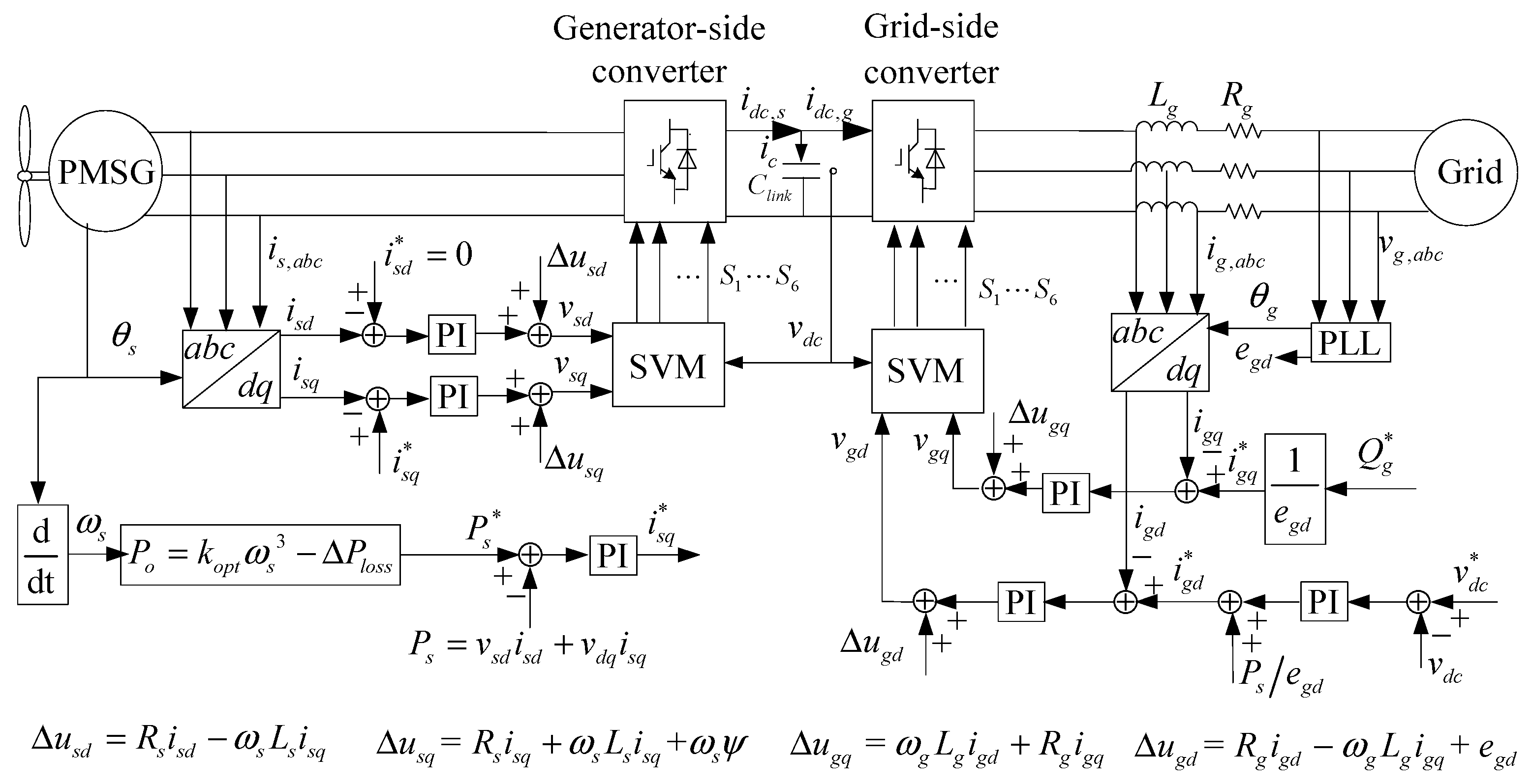
Figure 2.
The diagram of an improved control strategy of LVRT based on active power coordinates’ control. DSOGI-FLL, Dual Second-Order Generalized Integrator Frequency-Locked Loop.
Figure 2.
The diagram of an improved control strategy of LVRT based on active power coordinates’ control. DSOGI-FLL, Dual Second-Order Generalized Integrator Frequency-Locked Loop.

Figure 3.
E.ON’s reactive current support requirements [4].
Figure 3.
E.ON’s reactive current support requirements [4].
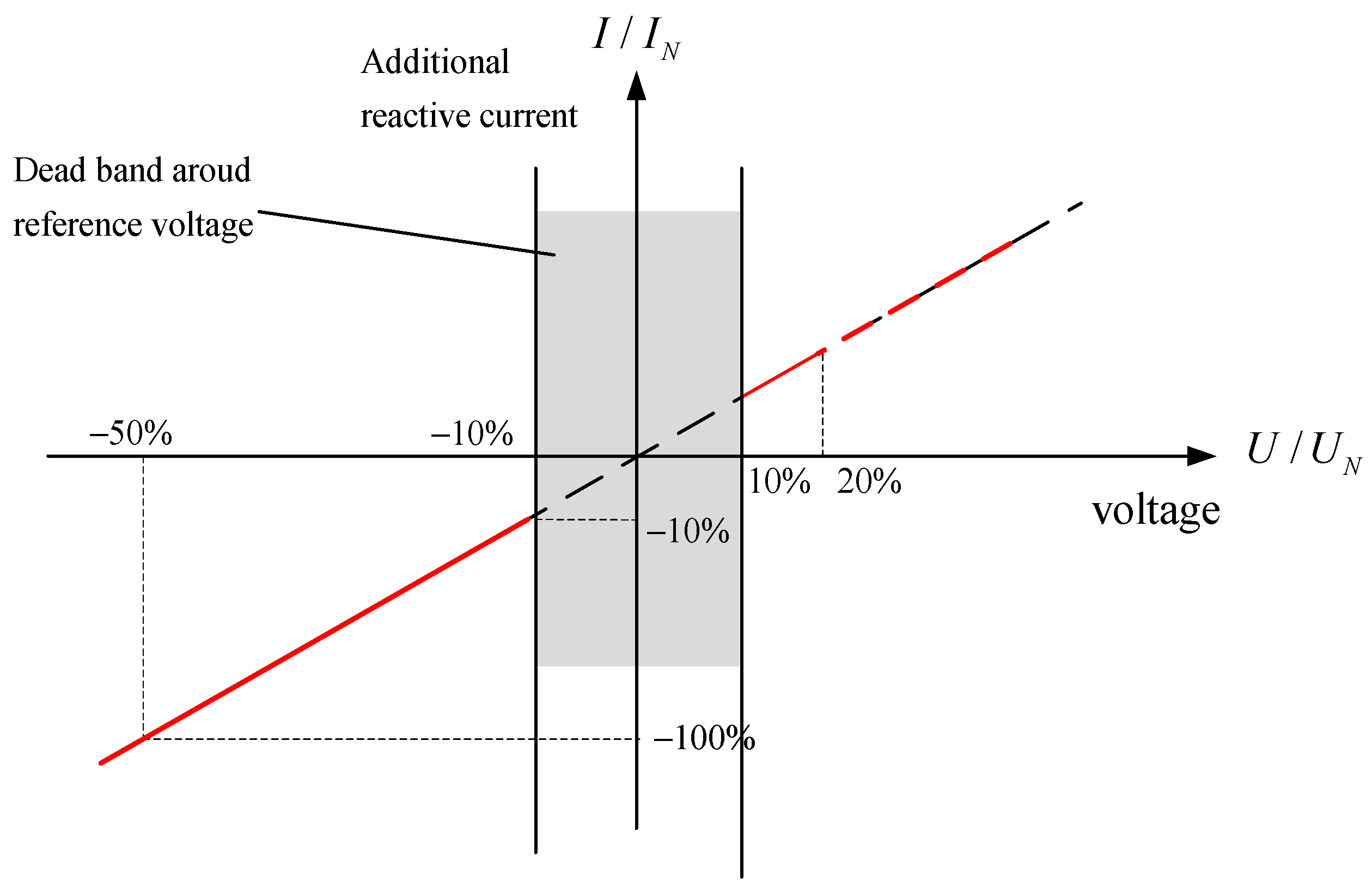
Figure 4.
Simplified block diagram of the DC-link voltage control.
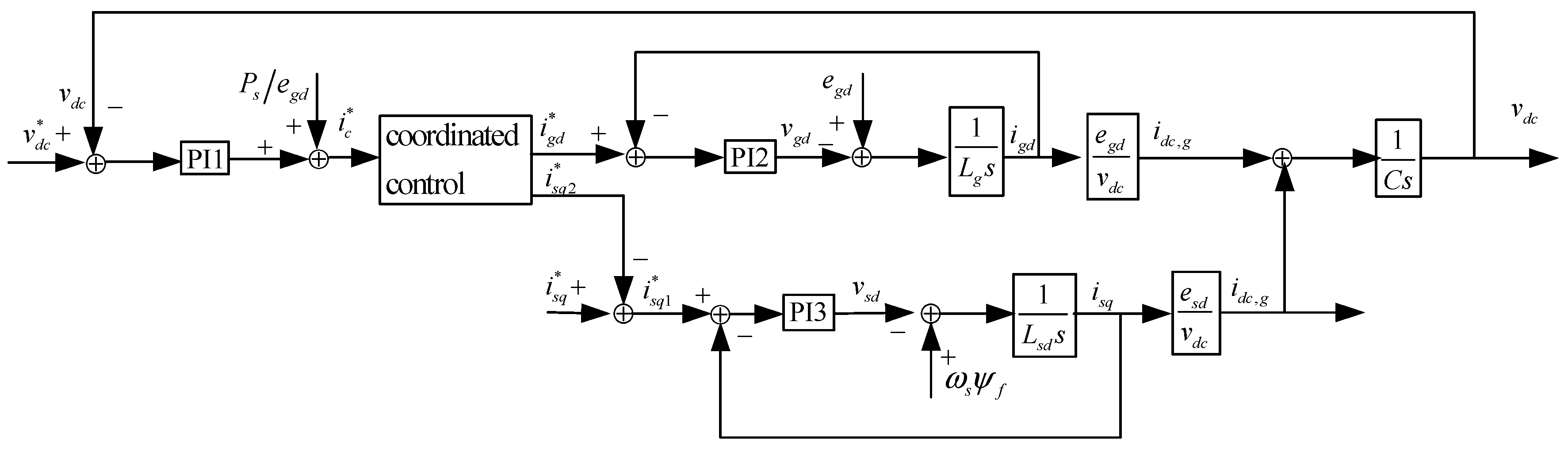
Figure 5.
(a) The step response curves and (b) The Bode plots of the systems with different inner loops.
Figure 5.
(a) The step response curves and (b) The Bode plots of the systems with different inner loops.
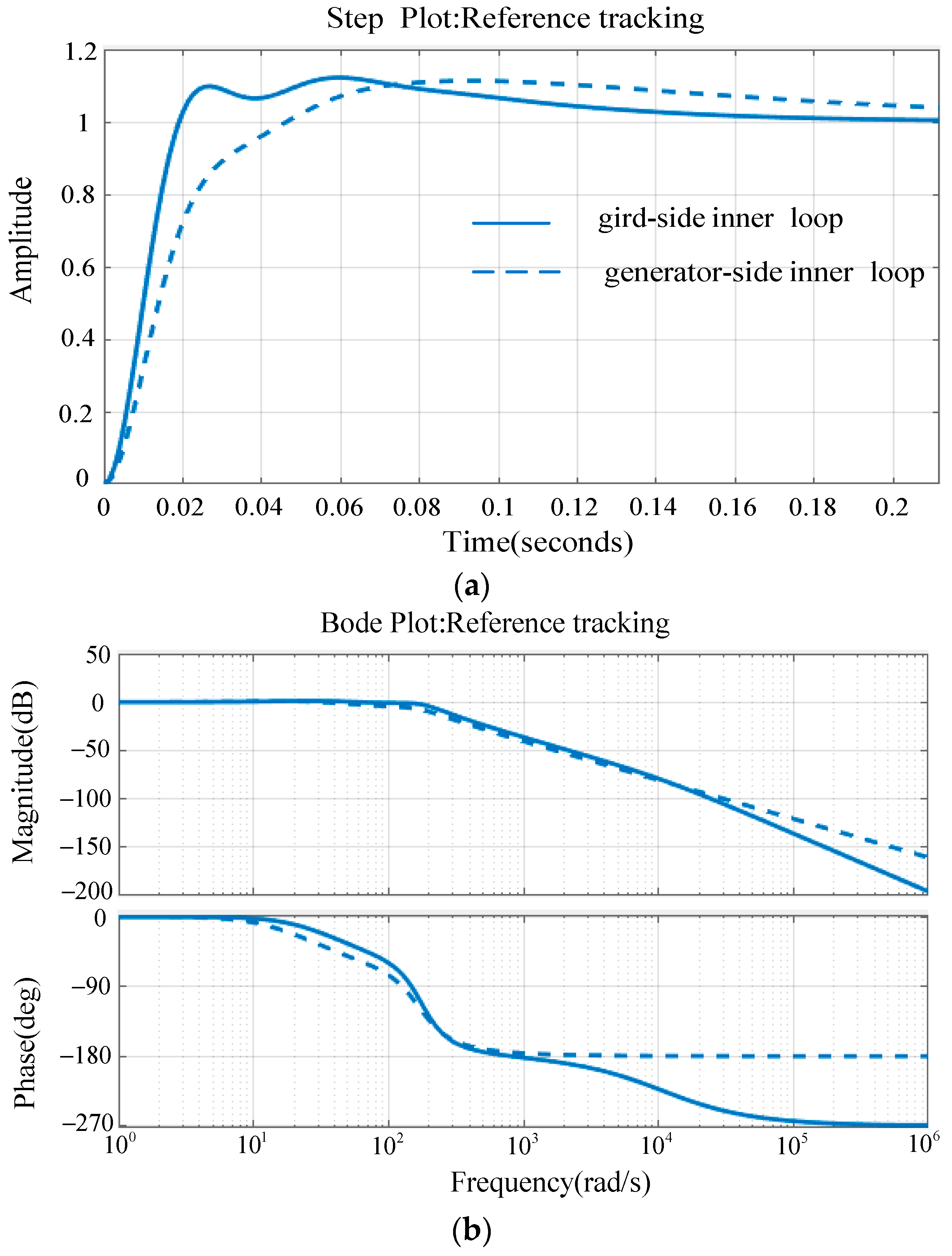
Figure 6.
Control block diagram of VCCF.
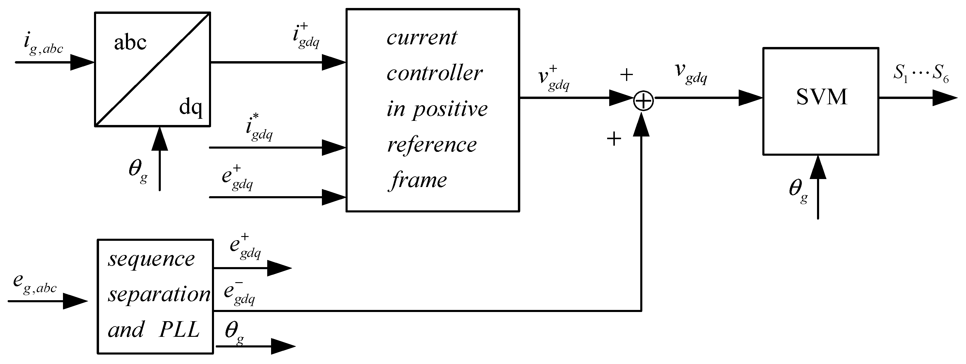
Figure 7.
Positive- and negative-sequence components of the grid voltage dip of 50% using different methods. (a) Test voltage signals; (b) Low-Pass Filter (LPF); (c) Delayed Signal Cancellation (DSC); (d) DSOGI-FLL.
Figure 7.
Positive- and negative-sequence components of the grid voltage dip of 50% using different methods. (a) Test voltage signals; (b) Low-Pass Filter (LPF); (c) Delayed Signal Cancellation (DSC); (d) DSOGI-FLL.

Figure 8.
Block diagram of the DSOGI-FLL.
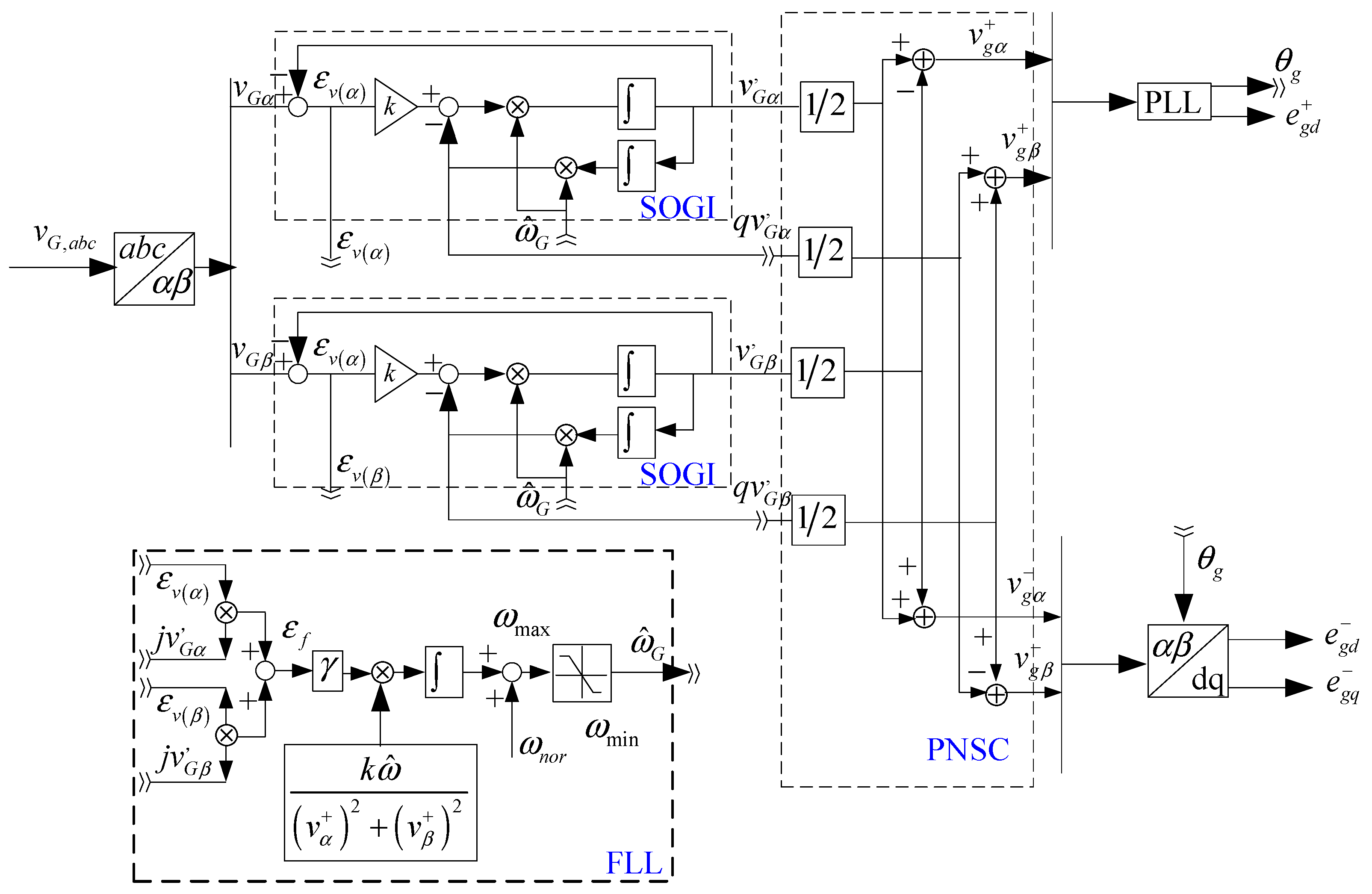
Figure 9.
Curves of the grid-voltage dip.

Figure 10.
Simulation results of the voltage dips used in the method of [19].
Figure 10.
Simulation results of the voltage dips used in the method of [19].

Figure 11.
Simulation results of the voltage dips by the propose method used in the paper.

Figure 12.
The critical simulation waveforms under the asymmetric voltage drop: (a) without negative voltage feed forward; (b) with negative voltage feed forward.
Figure 12.
The critical simulation waveforms under the asymmetric voltage drop: (a) without negative voltage feed forward; (b) with negative voltage feed forward.

Figure 13.
Experiment setup overview.

Figure 14.
The experimental waveforms of voltage dips. Time: 100 ms/div; Ch1: DC-link voltage , 100 V/div; Ch2: Phase a grid-side current , 20 A/div; Ch3: Phase a grid-side voltage , 500 V/div; rotor speed , 5 V/div.
Figure 14.
The experimental waveforms of voltage dips. Time: 100 ms/div; Ch1: DC-link voltage , 100 V/div; Ch2: Phase a grid-side current , 20 A/div; Ch3: Phase a grid-side voltage , 500 V/div; rotor speed , 5 V/div.

Figure 15.
The experimental waveforms of voltage asymmetry dips with negative voltage feed forward. Time: 20 ms/div; Ch1–3: Phase a, b, c grid-side current , 10 A/div. ; Ch4: DC-link voltage , 100 V/div.
Figure 15.
The experimental waveforms of voltage asymmetry dips with negative voltage feed forward. Time: 20 ms/div; Ch1–3: Phase a, b, c grid-side current , 10 A/div. ; Ch4: DC-link voltage , 100 V/div.
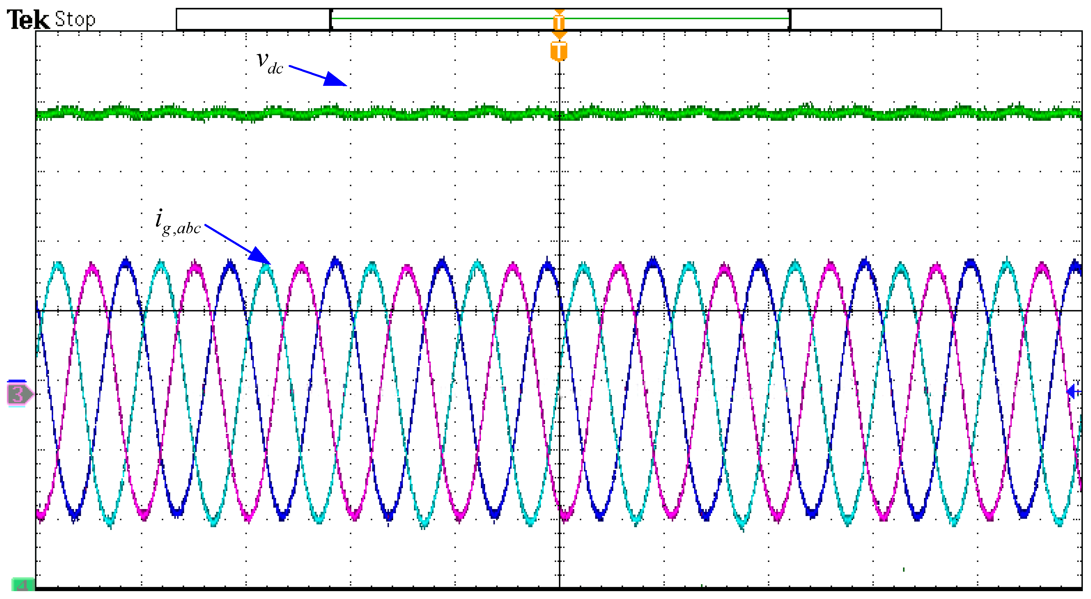
Figure 16.
The experimental waveform of voltage asymmetry dips without negative voltage feed forward. Time: 20 ms/div; Ch1: DC-link voltage , 100 V/div; Ch2–4: Phase a, b, c grid-side current , 10 A/div.
Figure 16.
The experimental waveform of voltage asymmetry dips without negative voltage feed forward. Time: 20 ms/div; Ch1: DC-link voltage , 100 V/div; Ch2–4: Phase a, b, c grid-side current , 10 A/div.


Table 1.
The parameters of the PMSG wind power system for simulation.
| Wind Turbine Parameters | |
|---|---|
| Rated wind speed/m/s | 12 |
| Max. power conv. coeff. | 0.53 |
| Base power/MVA | 1.5 |
| Inertia constant/s | 4.8 |
| PMSG Parameters | |
| Rated power/MVA | 1.5/0.9 |
| Pole pairs of PMSG | 30 |
| Rated rotor speed/rad/s | 2.3 |
| Permanent magnet flux/wb | 7.44 |
| Stator resistor/Ω | 0.006 |
| d-axis reactance/mH | 1.56 |
| q-axis reactance/mH | 1.56 |
| Base voltage/V | |
| Base frequency/Hz | 11.25 |
| Inertia constant/s | 0.62 |
| Converter Parameters | |
| DC-link capacitor/mF | 12 |
| Grid-side reactance/mH | 0.35 |
| Grid-side resistor/Ω | 0.002 |
| DC-link rated voltage/V | 1100 |
| Switch frequency/Hz | 2000 |
| Grid- rated voltage/V | 690/sqrt(3) |
| Grid rated frequency/Hz | 50 |
Table 2.
The PI control parameters.
| PI1 Control Parameters | |
|---|---|
| Proportional Gain | 0.34 |
| Integral Gain | 22 |
| PI2 Control Parameters | |
| Proportional Gain | 1.2 |
| Integral Gain | 20 |
| PI3 Control Parameters | |
| Proportional Gain | 2.2 |
| Integral Gain | 150 |
Table 3.
Parameters of the PMSG for experiment.
| Generator | |
|---|---|
| Rated power | 13.8 kVA |
| Frequency | 60.3 Hz |
| Rated speed | 227.5 rpm |
| Rated voltage | 380 |
| Quadrature axis inductances | 4.6 mH |
| Direct axis inductances | 3.46 mH |
| Winding resistance | 0.234 Ω |
| Motor (Turbine Simulator) | |
| Rated power | 22 kVA |
| Frequency | 50 Hz |
| Rated current | 42 A |
| Rated voltage | 380 V |
| Converter | |
| Rated power | 15 VA |
| Grid voltage | 380 V |
| Switching frequency | 2 kHz |
| DC-link voltage | 750 V |
| DC-link capacitor | 4.7 mF |
| Grid Simulator | |
| Rated power | 30 kVA |
| Input voltage | 380 V |
| Output voltage | 0–380 V |
| Output maximum current | 42 A |
| Response time | 2 ms |
| Output Frequency | 40.00–99.99 Hz |
© 2017 by the authors. Licensee MDPI, Basel, Switzerland. This article is an open access article distributed under the terms and conditions of the Creative Commons Attribution (CC BY) license (http://creativecommons.org/licenses/by/4.0/).
Share and Cite
MDPI and ACS Style
Zhong, C.; Wei, L.; Yan, G. Low Voltage Ride-through Scheme of the PMSG Wind Power System Based on Coordinated Instantaneous Active Power Control. Energies 2017, 10, 995. https://doi.org/10.3390/en10070995
AMA Style
Zhong C, Wei L, Yan G. Low Voltage Ride-through Scheme of the PMSG Wind Power System Based on Coordinated Instantaneous Active Power Control. Energies. 2017; 10(7):995. https://doi.org/10.3390/en10070995
Chicago/Turabian StyleZhong, Cheng, Lai Wei, and Gangui Yan. 2017. "Low Voltage Ride-through Scheme of the PMSG Wind Power System Based on Coordinated Instantaneous Active Power Control" Energies 10, no. 7: 995. https://doi.org/10.3390/en10070995
Note that from the first issue of 2016, this journal uses article numbers instead of page numbers. See further details here.