1. Introduction
Modern induction systems in spark-ignition (SI) engines are designed to produce controlled air intake in order to generate the appropriate turbulence inside the cylinder [
1]. The intake flow structure is further modified and broken down into small-scale eddies in the compression stroke, with the piston shape and chamber design influencing the turbulence decay rate in the cylinder [
2,
3]. The nature of the flow at the time of ignition determines the flame kernel development characteristics, and eventually, the combustion performance of the engine [
4]. The objective of this study was to correlate the characteristics of the early flame kernel to different 3D flow structures (combined swirl and tumble) of induction flows.
The flame kernel development period is the time over which the initial flame kernel propagates from the spark gap and begins to interact fully with the turbulent flow field [
5,
6]. This portion of the combustion time can reach 10% of the total fuel mass burning period [
4,
7,
8]. The fluid in between the electrodes of the spark plug can be considered a perfect insulator for electrical discharge flow. With the application of a high voltage from the ignition system, breakdown of the intervening air/fuel mixture occurs, and then electrons flow from one electrode (cathode) to the other (anode). After the breakdown of the impedance, an electrically conductive path is created between the electrodes. This conductive path is known as the spark or plasma channel. The temperature and pressure of this spark channel rise very rapidly to around 60,000 K and 20 MPa, respectively, as discussed in [
9,
10]. Due to these extreme conditions, supersonic expansion of the plasma channel with a strong shock wave occurs. Heywood [
10] approximated that the loss of energy by the shock wave expansion could reach up to 30% of the plasma energy. However, since the shock waves release most of their energy within a 2 mm diameter sphere of the spark center, the energy lost is regained soon afterward by the plasma kernel, due to its fast expansion (the kernel can expand up to 2 mm in diameter within 50 µs [
10,
11]).
The expansion process cools the ignition kernel to a lower temperature, and the arc and glow discharge phases bring a further cooling of the plasma; hence the temperature drops significantly. With the temperature drop, the combustion’s contribution to the plasma expansion becomes more important, and it reaches a point where the combustion prevails over the plasma kernel expansion. Eventually, this phenomenon ends the plasma kernel phase and commences the flame kernel or initial combustion phase. The combustion reactions at this stage are then sufficiently strong so to lead the expansion of the kernel without a supplementary energy supply from the spark plug. Ando and Arcoumanis [
11] described the early flame development stages in relation to the flame size: for a flame with a radius of less than 1 mm, its kernel growth was dominated by the ignition system properties. Up to a size of about a 2 mm radius, the kernel expansion rate was controlled by the balance between laminar flame speed and strain rate. Gradually, the flame kernel started to interact with the surrounding turbulent flow fields, and within the size of about a 10 mm radius, it acquired the property of a fully developed flame structure. The fuel fraction burned in this period could reach 10% of the total mass.
The early flame development is strongly affected by the level of turbulence in the vicinity of the spark electrodes [
4,
8]. The flow surrounding the spark electrodes at the time of ignition consists of different-scale turbulent eddies, depending on the nature of the induction flow (tumble or swirl) and the magnitude of generated squish (a radially inward flow) in the compression stroke near top dead center (TDC). Ting et al. [
12] compared the impact of low-frequency, large-scale eddies and high-frequency, small-scale eddies on the early developing flames. They related the high-frequency, small-scale eddies’ effect as a flame-turbulence interaction that can affect combustion rates in the early portion of the combustion period, whereas the low-frequency, large-scale eddies were related to the flame–electrodes/wall interaction that could quench the early flame. They found a strong relationship between the high-frequency, small-scale eddies at the time of ignition and the flame growth rate. The large-scale eddies (eddies larger than the flame size) and the bulk flow were found to convect the flame away from the spark electrodes. Xiong et al. [
13] performed an experimental investigation to study the interaction between flame kernels and vortices. The outcome of their investigation was that the vortical flow was found to enhance the flame growth rate highly, as it interacted with the early flame (when the flame was considered to be very small). In addition, they found that the vortex strength had a significant impact on the early flame growth, rather than the vortex size. On the other hand, Aleiferis et al. [
4] showed initial flame growth and wrinkles relations that seemed contradictory to the other works on small-scale flow effects on the growth rates, such as the works of [
12]. Their study [
12] demonstrated the benefits of flame convection on the growth rate in the earliest portion of flame development, which was mostly due to the large-scale flows and the bulk mean velocity. It was found that the vortex-flame kernel interaction depended on the size of the early flame, as well as the equivalence ratio of the charge. Marley et al. [
14] investigated this, and found that when a vortex interacted with a 5 mm radius (small) flame kernel, a substantial rise in the burning rate was observed for a lean mixture, whereas the burning rate decreased for a rich mixture. However, the vortex interaction with a larger flame size, a 30 mm radius, resulted in a moderate flame growth enhancement for both lean and rich mixtures. Lee et al. [
15] also mentioned the importance of turbulence enhancement to the lean flame growth.
Generally, the works mentioned earlier showed the nature of the early flame kernel and its interaction with the turbulent flow in the vicinity of the spark plug. The current study relates the early flame characteristics with the variable induction flow types. Parameters such as flame distortion, flame wrinkles, flame position (relative to spark center), and displacement were observed; their influence on flame growth rate was analyzed.
2. Experimental Methods and Analysis Techniques
A single-cylinder direct-injection (DI) spark-ignition research engine with an optical access to the combustion chamber was used for the study. The engine specifications are given in
Table 1. The engine setup was similar to the engine reported in Hagos et al. [
16]. Both intake ports were fitted with swirl control valves (SCVs) to adjust the swirl levels at the air intake. The adjustment was at the three available pinning positions of the SCV flow-diverting flaps inside the two divided intake ports. The SCV adjustments and the nature of induction flow for the different adjustment cases are given in
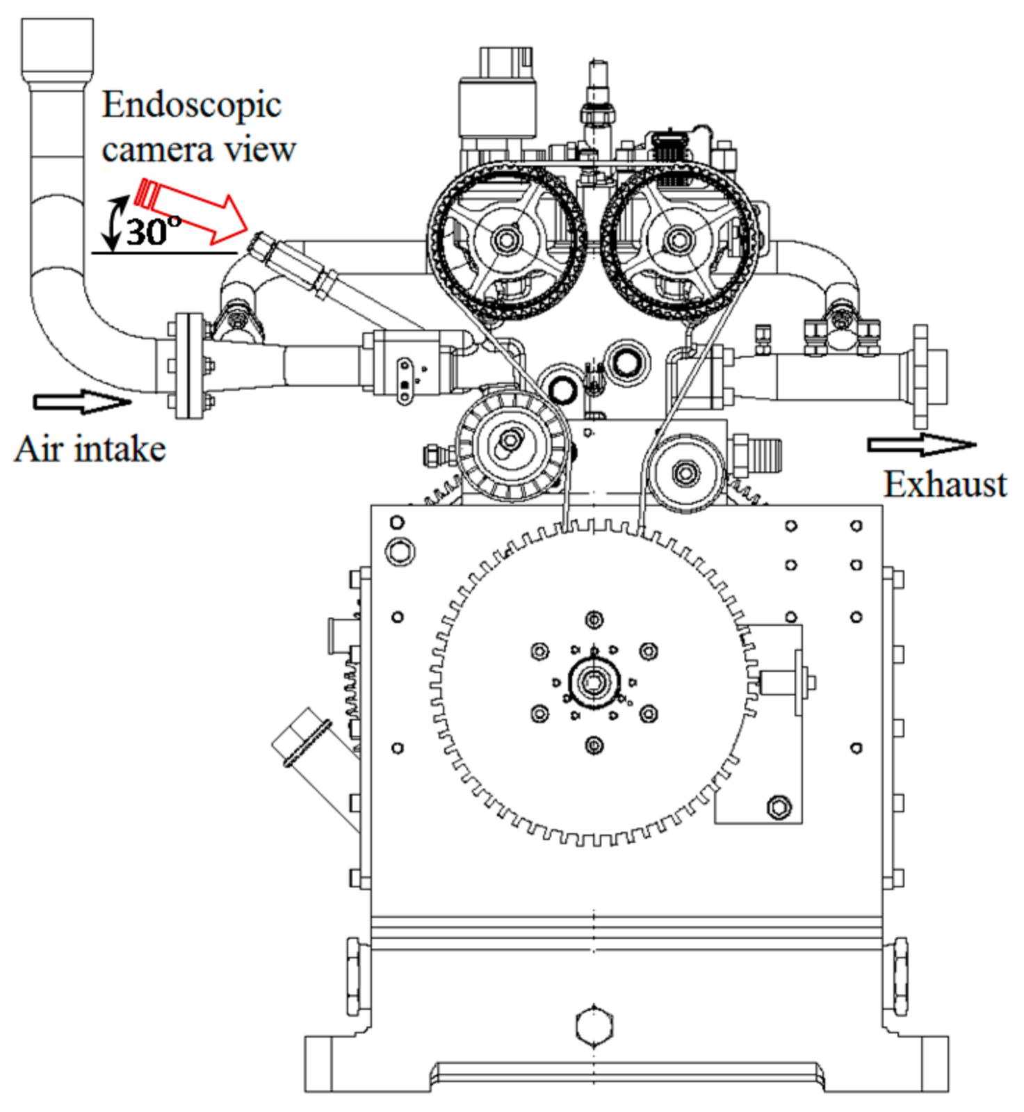
Table 2. The detailed induction flow structure investigation was performed on a separate setup using the actual cylinder head and a transparent cylinder, by using the particle image velocimetry (PIV) flow measurement and analysis technique. This induction flow analysis is the subject of a separate paper by the authors. Optical access into the engine cylinder was available through a 10 mm diameter hole for the camera endoscope at the intake side with 30° installation angles, and another similarly sized hole was used for laser access with a 16° installation angle, normal to the camera viewing direction.
Engine speeds of 1500 rpm, 1800 rpm and 2100 rpm were considered for the current study. The inlet valve closing in the engine under study was at a 132° crank angle (CA) before TDC (BTDC). Fuel injection timing was set at 90° BTDC for the stratified case (after the inlet valve closed) and 180° BTDC for the homogeneous mixture case (before the inlet valve closed). Equivalence ratios (Φ) of 0.50 for the stratified charge and 0.71 for the homogeneous charge combustion were used with the ignition timing set at 38.5° BTDC for all cases. The equivalence ratios were obtained from the oxygen analyzer. Charge stratification was achieved by delaying the injection timing in order to reduce the available time for the fuel/air mixture preparation before the ignition onset, as well as by using a stratifying piston (with a large central bowl).
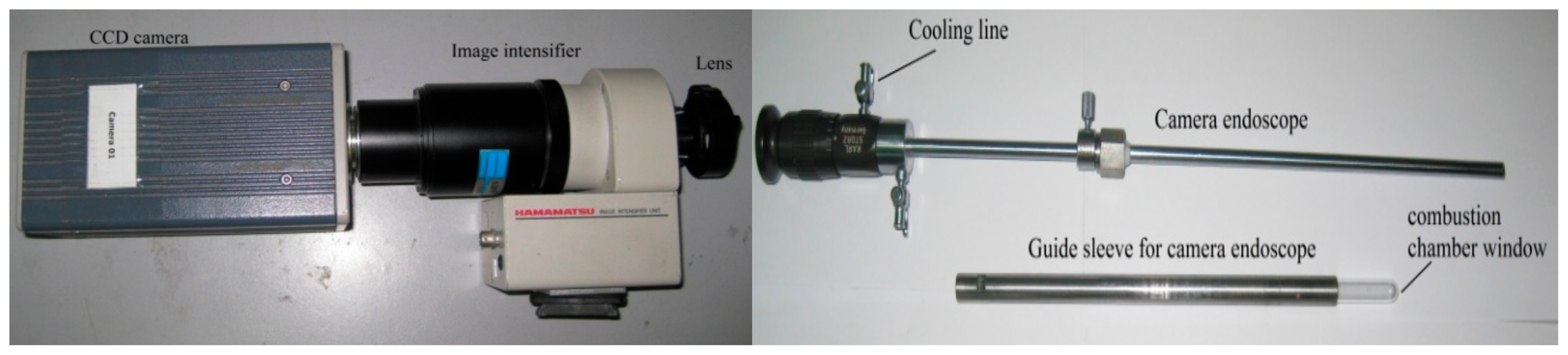
The flame imaging devices used for the study were a HiSence 12 bit CCD camera (Dantec Dynamics, Tonsbakken 16, 2740 Skovlunde, Denmark) and Hamamatsu CA2098 image intensifier (Hamamatsu Photonics, Hamamatsu, Japan) to strengthen the weak flame intensity, also shown in
Figure 1. The in-cylinder combustion process of the current engine was accessible only through an endoscopic hole. A similarly accessed engine is also reported elsewhere [
6,
17]. Therefore, a camera endoscope of type AVL KARL STORZ M00060 30° (KARL STORZ, Mittelstr. 8, 78532 Tuttlingen, Deutschland) was attached to the imaging device, inserted into the cylinder, and steered 30° to image the vertical in-cylinder plane view on the CCD camera, as shown in
Figure 1 and
Figure 2. The endoscope was provided with compressed air at 6 bar for cooling purposes, to reduce the image distortion due to an elevated working temperature.
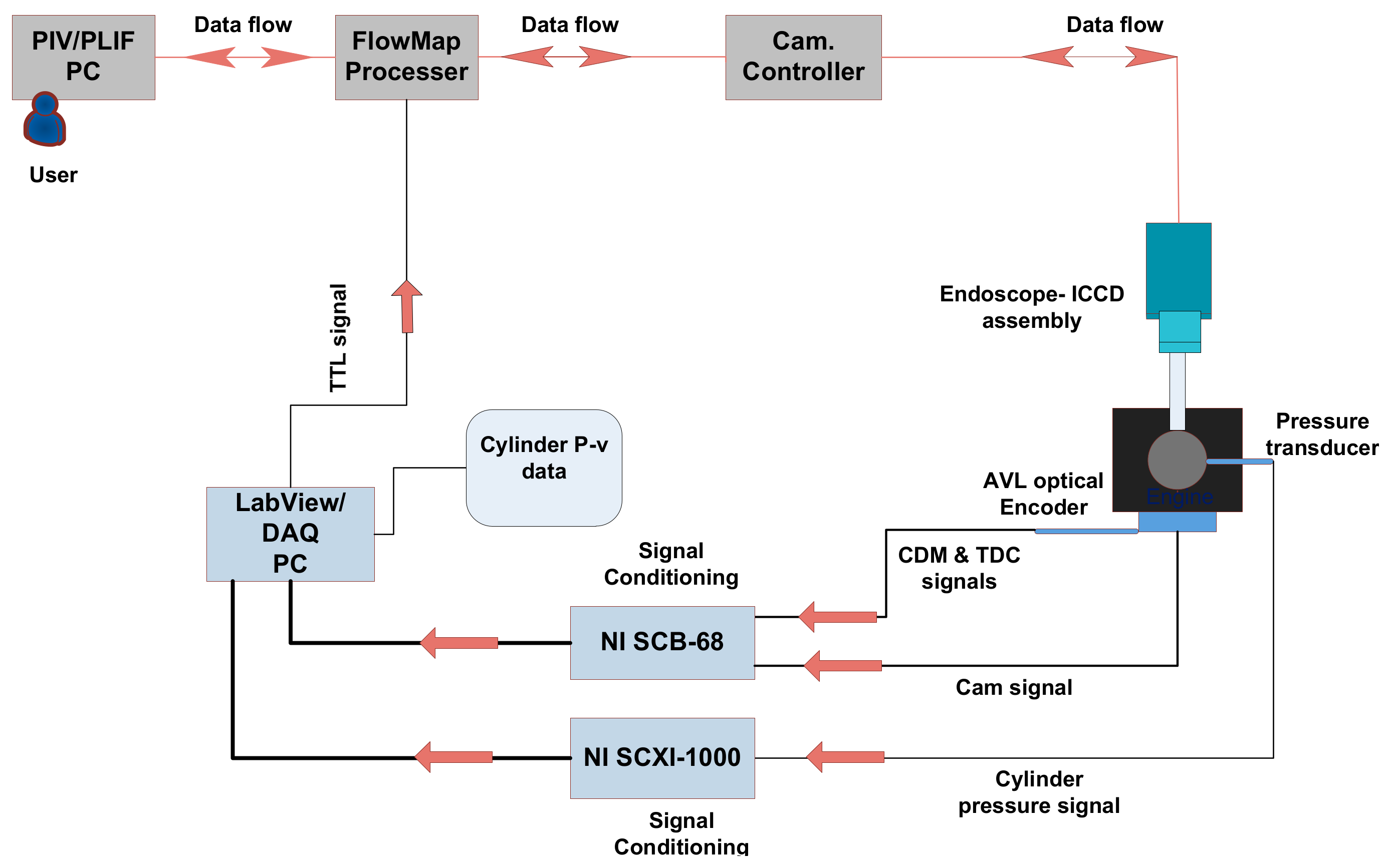
The procedure for data collection was first to adjust the SCV positions, and to then set the engine speed. Thirty flame images were collected at every set CA, with 2° CA intervals starting from 38° CA BTDC (i.e., 0.5° CA BTDC after ignition onset). The imaging system was triggered at the set CA by a Transistor–Transistor Logic (TTL) signal generated from a LabView 8.0 system based on cam and CA encoder signals from the engine, as shown in
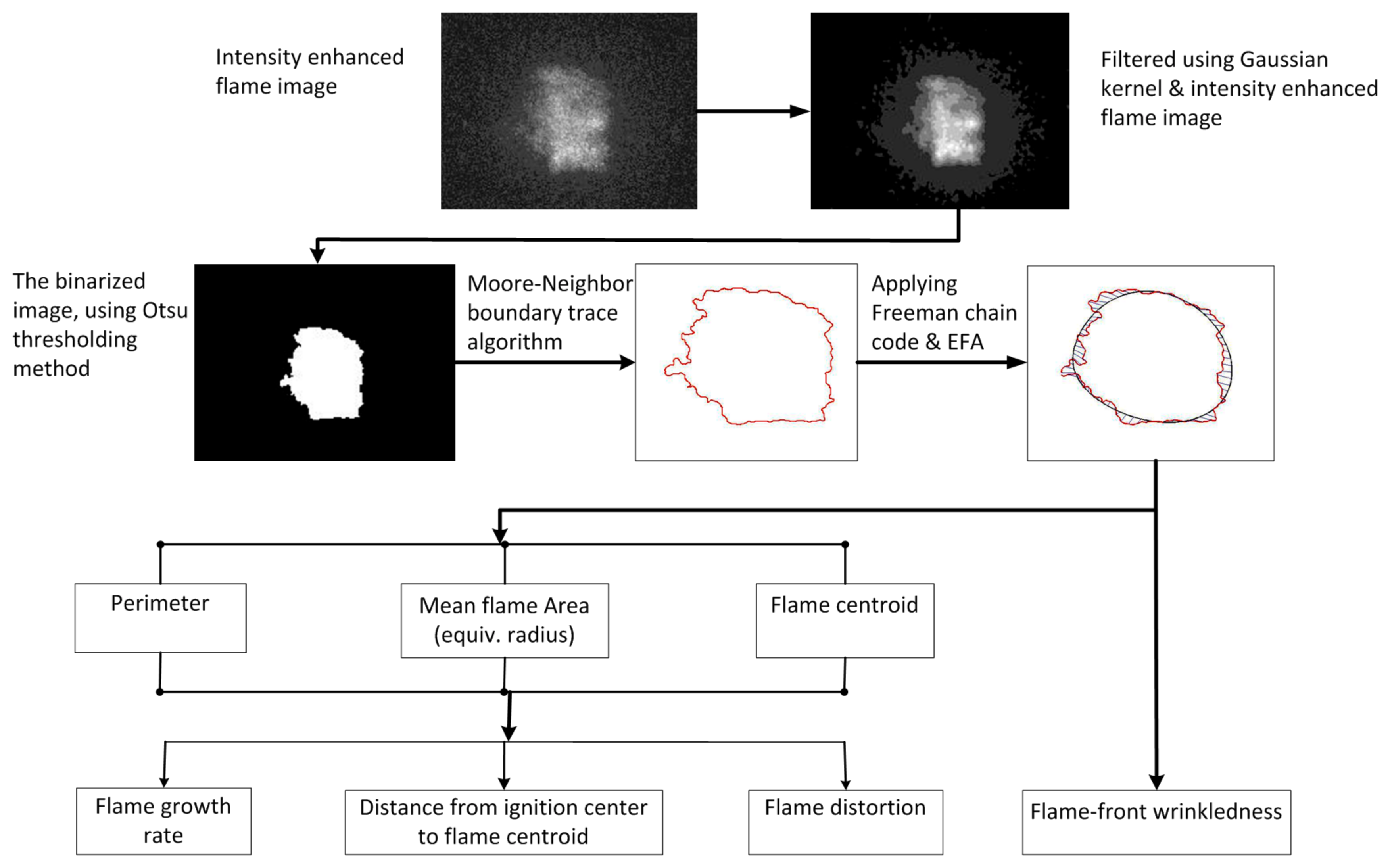
Figure 3. Computer code was developed in order to analyze the flame images quantitatively. The basic analysis procedure is shown in
Figure 4. The flame image captured by the camera first passed through an intensity enhancement and filtering process. Then, the binary image was generated by segmenting the flame from its background using the Otsu thresholding technique as discussed in [
18]. The Otsu thresholding technique is based on the probability distribution of the flame image gray-level histogram and the statistical classification of intensity levels into classes of foreground and background at a given threshold value. A statistical procedure was employed to identify the optimum threshold value that maximized the class variances between the foreground and background intensity signals. The outer contour of the binary image was then identified using a Moore-Neighbor tracing technique, and the vertices that constituted the contour were found.
Both Freeman chain code and elliptic Fourier analysis (EFA) techniques were used to characterizing the flame boundaries. First, the motion along the boundary was coded with the 8-direction Freeman chain code (shown in
Figure 5). Using the outputs of the chain code, a truncated Fourier series expansion of the flame contour projected on the x and y axes was identified by
where
t is the step required to traverse one pixel along the closed contour,
for
, and
k is the total number of codes describing the boundary contour.
J represents the total number of Fourier harmonics needed to regenerate the exact approximation of the flame contour.
T is the basic period of the chain code,
T = tk, and
A0 and
B0 are the bias coefficients.
Each elliptic Fourier harmonic has four coefficients. The
jth set of these coefficients can be given as follows (as elaborated in [
19]):
where
and
are the spatial changes in the
x and
y projections of the chain code, respectively, at link
p.
is the step change required to traverse link
p of the chain code.
is the number of steps required to traverse the first
p components or links of the chain code.
3. Early Flame Analysis
The flame characteristics considered for analyses were the levels of flame wrinkles and flame distortion, as well as the position and displacement of the flame relative to the spark center, and the flame growth rate. The analysis was carried out for both the stratified and homogeneous combustion cases at different engine speeds and induction swirl levels. Stratified charge is a process of creating different fuel/air ratio regions inside the combustion chamber. These are created by injecting the fuel late; thereby the injected fuel will be redirected back to the spark plug region. A rich fuel/air mixture is created near the spark plug, while the overall mixture strength remains lean. In the homogeneous charge, however, fuel is injected early to allow the fuel and air to completely mix. The mixture strength throughout the combustion chamber is uniform.
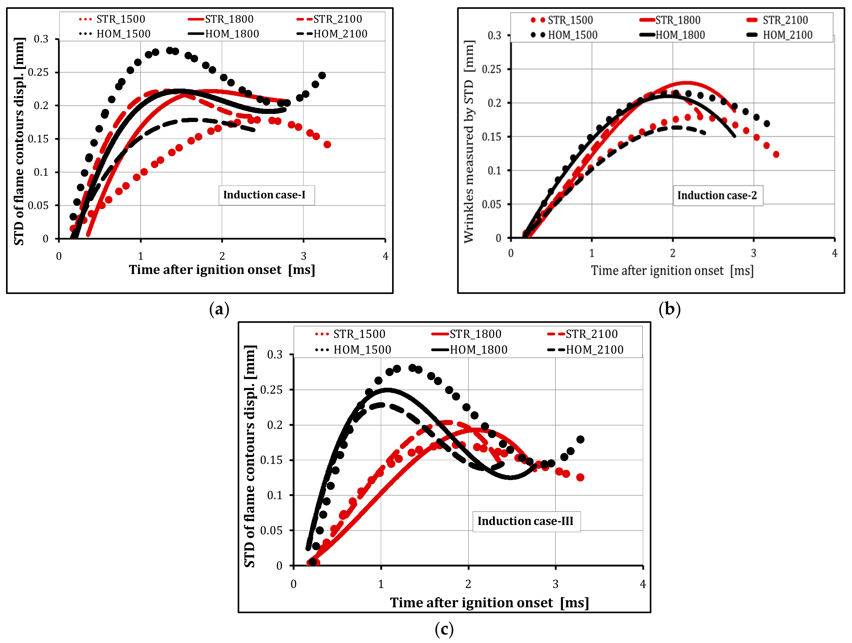
3.1. Flame Wrinkles
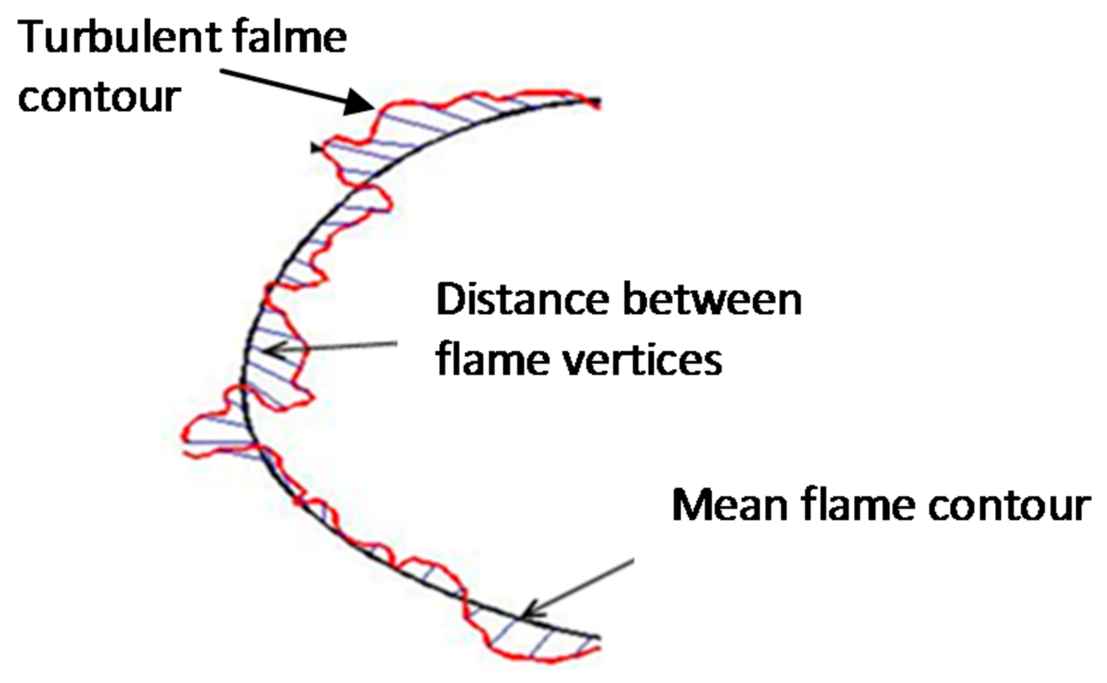
The level of the flame wrinkles was estimated from the measurement of the displacement of vertices between the mean and turbulent flame contours, as shown in
Figure 6. For this purpose, computer code was developed for an automatic measurement of the displacement. The number of measured distances depended on the number of vertices that defined the contour. The standard deviation of these measured distances was taken as a measure of the level of the flame front wrinkledness.
Figure 7 shows the level of wrinkles obtained for all induction cases under consideration at the three different engine speeds (1500 rpm, 1800 rpm and 2100 rpm) for both stratified and homogeneous charge combustions. It was observed that the wrinkle formations for the stratified and homogeneous combustion flames were different. Generally, in the stratified charge combustion, the flame’s wrinkle level increased with the engine speed, whereas in the case of homogeneous charge combustion, an opposite behavior was observed, as depicted by the curves in
Figure 7.
The local air/fuel ratio at the vicinity of the spark electrodes in a stratified charge can be rich or near stoichiometric, whereas in the case of a homogeneous mixture, the local air/fuel ratio is about the same as the overall air/fuel ratio. The measured overall Φ for stratified and homogeneous combustions were 0.50 and 0.71, respectively. It was presumed that the early flame of the stratified charge combustion grew in a richer air/fuel mixture, compared to the homogeneous charge combustion. Arcoumanis and Kamimoto [
11] explained that a lean mixture could exhibit a higher degree of wrinkledness because the burn rate is lower than the wrinkling rate due to turbulence. On the other hand, Heim and Ghandhi [
20] investigated the in-cylinder flow characteristics at different engine speeds, and showed that the turbulence intensity has a linear relationship with the engine speed. A rise in engine speed can increase the in-cylinder turbulence intensity, which promotes the degree of flame wrinkledness [
11]. Therefore, the wrinkle level of the early flames shown in
Figure 7 could be the result of the tradeoff between the mixture leanness and the level of turbulence created due to engine speed variations. It can be seen from the results that the maximum wrinkle level observed on the early flames occurred in the homogeneous combustion case at 1500 rpm. In the case of stratified combustion, where the local air/fuel ratio in the spark electrodes region was near stoichiometric (or rich), an increase in the engine speed was shown to increase the level of wrinkles (
Figure 7).
As stated earlier, the effect of engine speed on the level of flame wrinkles was found to be a function of the combustion mode (stratified or homogeneous). The flame kernel in the stratified combustion mode started in a richer charge mixture at the spark center and propagated through a lean charge towards the cylinder wall. It is generally accepted that rich flames burn faster than lean flames [
11]. For the homogeneous combustion mode, more flame wrinkling was observed at lower engine speeds, which was thought to be due to the relatively longer available time for mixture formation for a similar start of injection (SOI) timing. This, in turn, would lead to a leaner early flame formation and hence a slower flame burn rate. Therefore, wrinkles on the flame surface were formed faster than they were consumed by the flame front, resulting in a higher level of flame wrinkling for the lower engine speeds. It was also observed that the level of flame wrinkling at higher engine speeds increased with the increase in the degree of charge swirl ratio from case 1 (medium-tumble induction) through to case 3 (high-swirl induction) for both stratified and homogeneous charges, as shown in
Figure 7.
The flame surface wrinkles were also found to depend on the mode of combustion, with the homogeneous combustion generally showing a higher degree of flame wrinkling, for all induction cases, than in the case of the stratified mixture. Increasing the engine speed enhanced the degree of flame front wrinkling in the stratified combustion case. At 1800 rpm, very little differences were observed between stratified and homogeneous combustions, whereas at 2100 rpm, the stratified combustion showed a higher level of wrinkling of the flame surfaces for the first two induction cases. The engine speed was found to have a little effect within the first 1 ms after the ignition onset in case 3 induction.
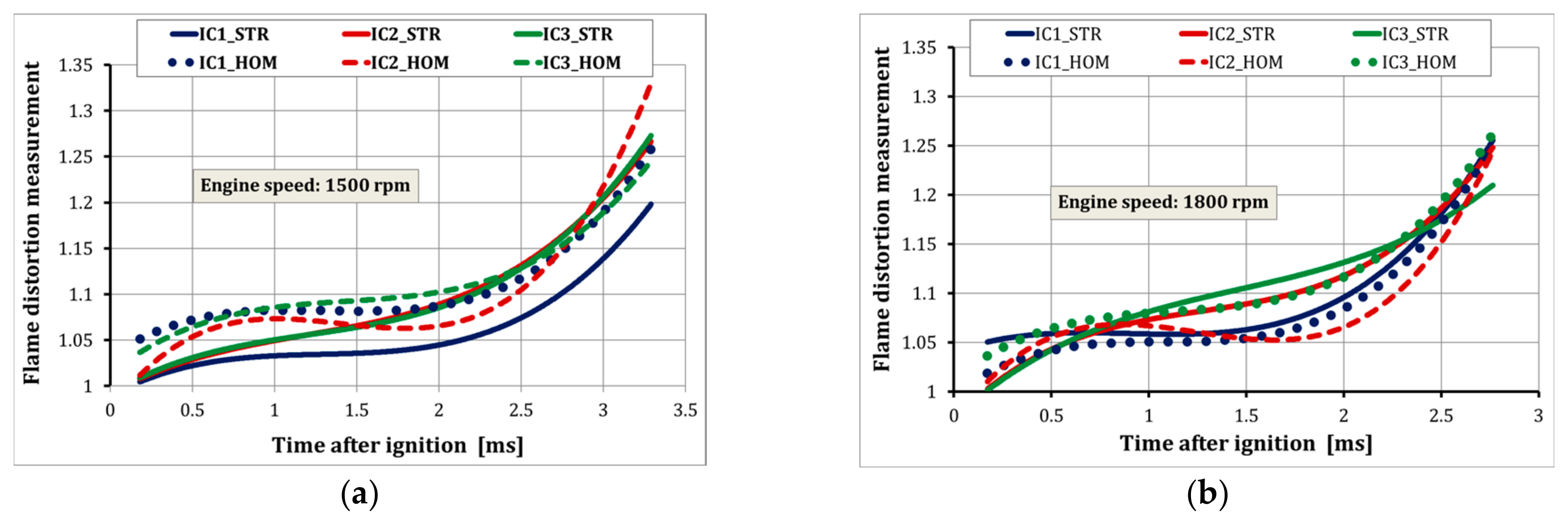
3.2. Flame Distortion
Flame distortion is a measure of the global change in the flame structure or shape [
21]. The early flame can be distorted due to its interaction with large-scale flow structures, due to local quenching of the flame by contact with cold surfaces, such as spark electrodes, and/or due to hydrodynamic strain effects of the in-cylinder bulk flow [
22,
23]. In this study, distortion was measured by the ratio of the mean flame perimeter to the perimeter of a circle of equivalent radius, similar to the works of [
8,
24,
25]. Here, the mean flame contour perimeter was considered for the calculation, instead of the actual turbulent flame, in order to avoid the effect of small-scale local curvature changes due to wrinkling. This way, only the effect of the large-scale flow structures on the flame distortion was considered.
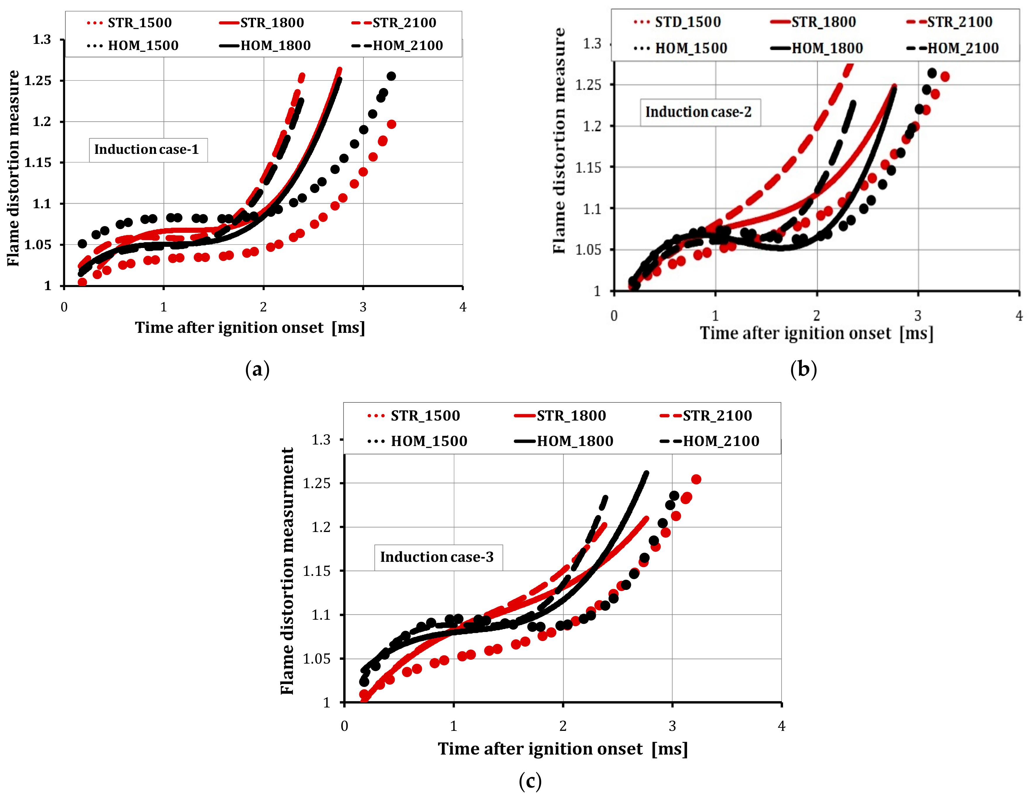
Distortion of the early flame for the different engine speeds and induction flows is shown in
Figure 8. Generally, the results showed that the level of flame distortion increased with the increase in the engine speed in all cases of induction for both the stratified and homogeneous charge combustions. This is believed to be a direct result of the increase in the mean bulk velocity with the engine speed. A higher rate of distortion was noticed after 1.5 ms from the ignition onset, especially in the medium- and high-swirl cases. The medium-swirl case at 2100 rpm exhibited the highest degree of distortion from 1 ms after ignition onwards (
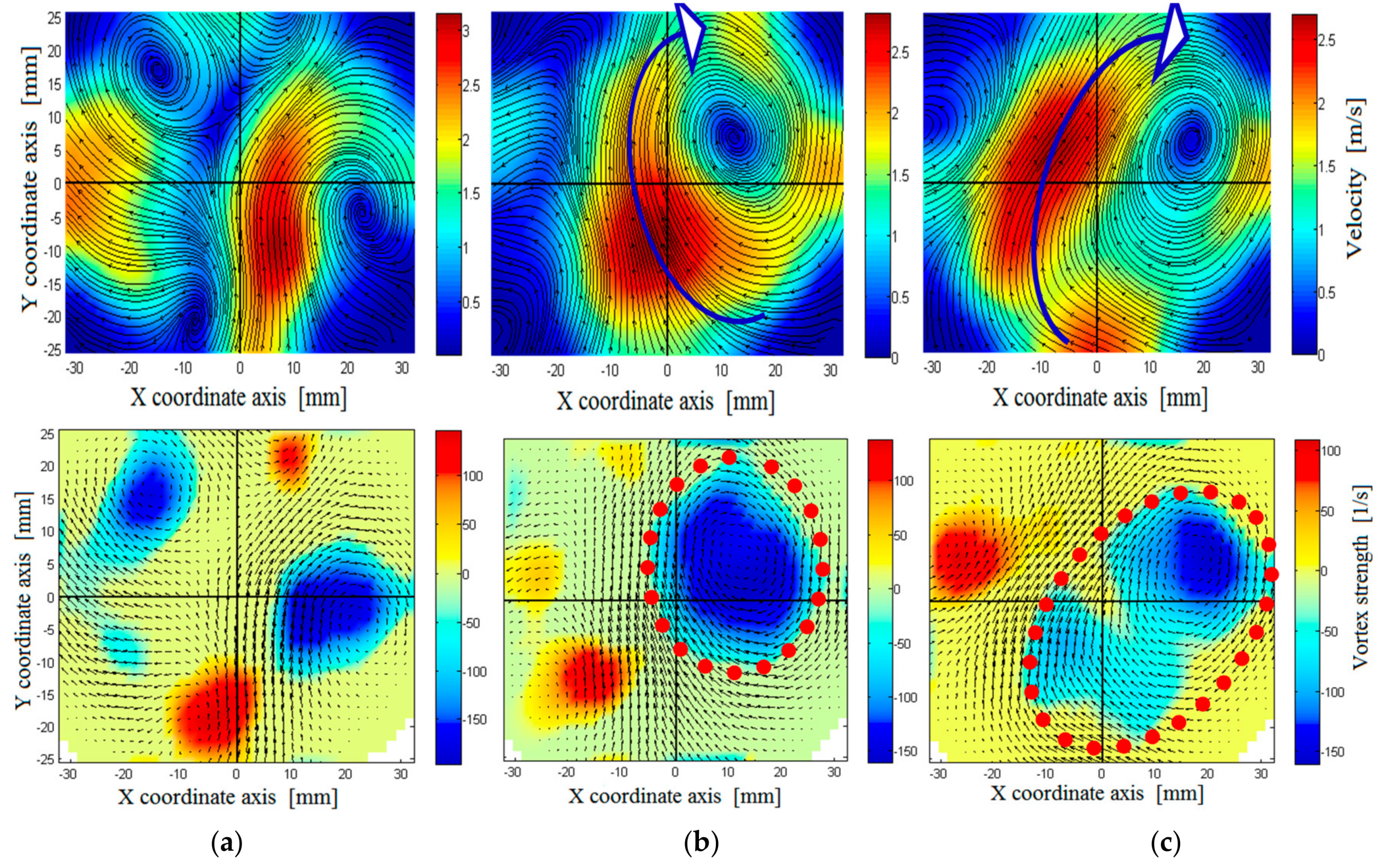
Figure 9). The intake flow structures of the different induction cases shown in
Figure 10 revealed the formation of large and strong swirling cores in the medium- and high-swirl inductions, which led to a lower rate of breakdown of the large-scale flow structures during the compression stroke. Therefore, large-scale flow structures dominated the flow at the time of ignition near the spark plug, which resulted in a higher flame distortion.
x- and
y-directions in
Figure 10 represent the distance from the center of the cylinder. The flow visualization for the swirl plane was taken from the top of the piston.
The distortion data of
Figure 8 are replotted in
Figure 9 for the different engine speeds. As can be seen, case 1 induction (medium-tumble intake) exhibited the least flame distortion in the stratified combustion, whereas both partially closed SCV inductions (cases 2 and 3) showed nearly similar behavior. The nature of the distortion in the homogeneous mode showed little differences from the stratified. It can be concluded that the formation of swirl during the induction process by partially closing the SCV increased the early flame distortion in both the stratified and homogeneous modes for cases 2 and 3. In case 3 induction, where a large swirling core was formed, more significant distortion occurred. It was also observed that case 1 induction produced less early flame distortion, when compared to the other induction cases. In case 1, large-scale flow exhibited a coherent vortical flow in the tumble plane, as well as multiple vortices in the swirl plane. It is worth noting here that tumble inductions suffer from faster turbulence decay during the compression process, compared to swirl inductions [
10,
26]. Therefore, at the time of ignition, the flow near the spark center was dominated by small-scale eddies that had a lower capacity for distorting the early flame.
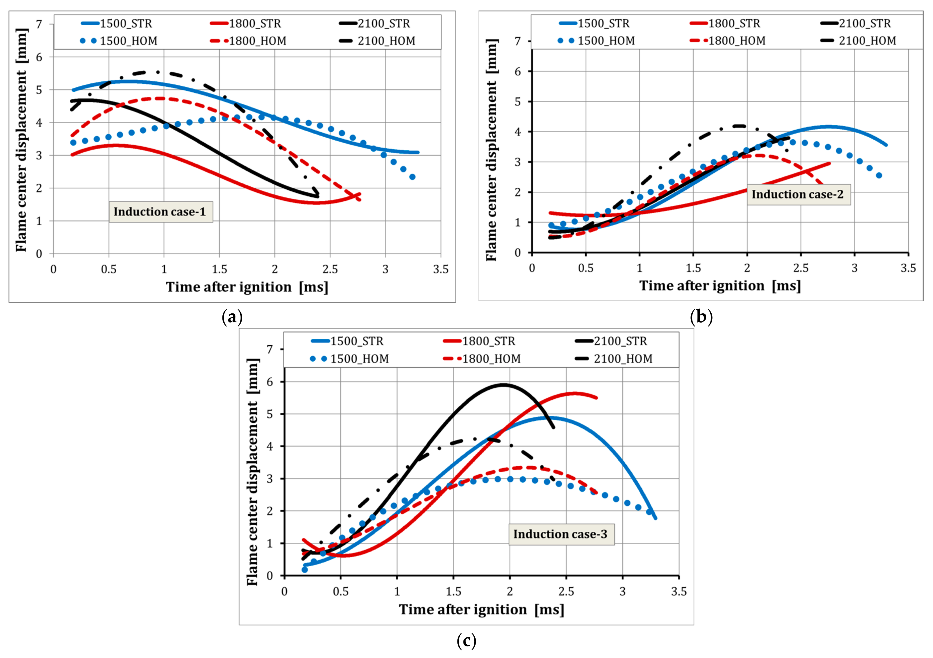
3.3. Flame Position and Displacement
Flame displacement is the Euclidean distance measured between the spark and the flame centers. The spark center was taken to be the center of the gap between the spark electrodes. The ignition kernel can be displaced from the spark center at a very early stage, as early as the arc phase [
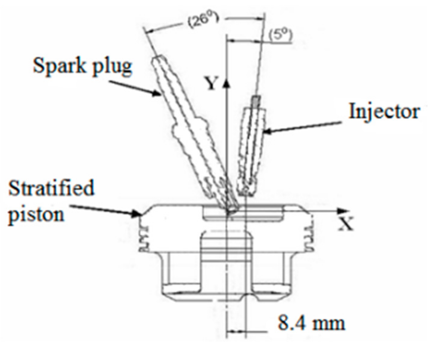
11]. The displacement from the spark center can be affected by the bulk flow velocity and the random motion of the large-scale turbulent eddies. Squish flow can have its own influence on convection of the early flame. As discussed in [
10,
26], squish can be intensified with an increasing swirl level and elevated mean piston speed. The direction of this squish flow during the compression process is generally radial and downwards in the cylinder. However, since the bowl in the current piston had an center offset (8.4 mm) from the cylinder axis (
Figure 11), the squish flow direction might have been diverted to the direction of the bowl center. This was likely the case when the piston approached TDC; the flame center was displaced to the direction of the bowl center (to the right, as shown in
Figure 12). The convection of the flame away from the spark center, especially in the early stages of flame development, was helpful to avoid or reduce local or global quenching of the small flame ball by reducing the chances of contact with the spark electrodes.
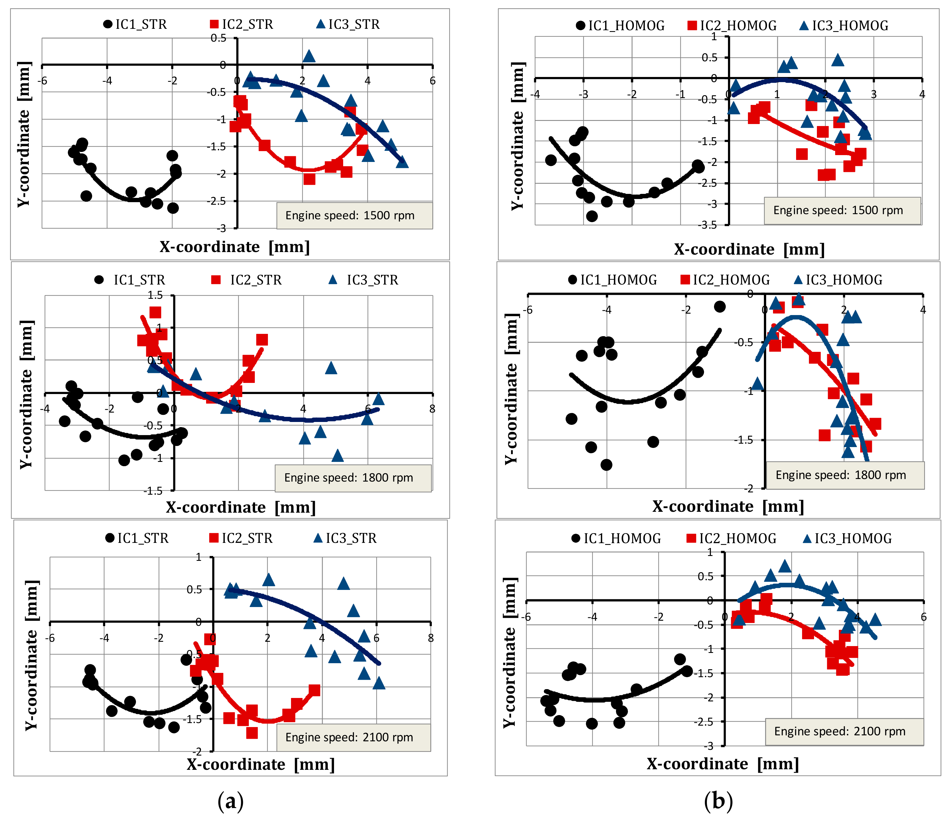
The displacement and position of the flame center in reference to the spark center, which was taken to be the center of the coordinate axes, is plotted against time in
Figure 12 and
Figure 13 for the stratified and homogeneous combustion modes at different engine speeds for different induction flow cases. It can be seen that the position of the flame centers and their displacement from the spark center were affected by the condition of the induction flow. In case 1 (medium-tumble induction), the early flame kernels captured by the imaging device at about 0.15 ms after the ignition onset were located 3–5.5 mm from the spark center in both the combustion modes and at all engine speeds, as shown in
Figure 12. Then the early flame kernel was pushed to the piston bowl center position (right side of ignition center) and slightly upward, due to the piston motion towards TDC, and likely due to the squish flow generated late in the compression stroke. The Euclidean distance between the flame and spark centers increased slightly at first, before declining, as shown in
Figure 12 and
Figure 13 for induction case 1. It was observed that the early flames of the medium-tumble induction case were located on the left-down position from the spark center for both combustion modes. The displacement of the flame was more radial as measured from the 2D vertical plane. This radial displacement of the early flame position was up to 3 times its axial displacement.
The flame center positions and displacements for induction case 2 (medium-swirl) and induction case 3 (high-swirl) showed a different trend from those of case 1 in both combustion modes for all engine speeds, as shown in
Figure 12 and
Figure 13. The early flame kernel images captured at 0.15 ms after ignition for the second and third induction cases were within 1 mm distances from the spark center. This close proximity of the early flames to the electrodes made the flames susceptible to heat losses and quenching (global or local), due to contact with the relatively colder electrodes. The radial displacement of the early flames in these induction cases was 3 to 4 times greater than the axial displacement, especially for the stratified charge combustion. The other important phenomenon noticed in cases 2 and 3 was that the flame centers were located completely on the right side of the spark center. Generally, early flame location in the cylinder depends on the type of induction flow that can have variable macro-flow structures. As demonstrated by
Figure 12, the flame kernels generated in case 1 (medium-tumble) were on the lower left side of the spark center, while in case 3 (high-swirl), they were on the right side of the ignition center, and in case 2 (medium-swirl), the flame kernel was somewhere between the position of the other two. The piston bowl used in this study was offset from the cylinder axis, as shown in
Figure 11, which could have created an offset swirl flow towards the right portion of the cylinder in cases 2 and 3. This perhaps was the reason for the convection of the early flame kernels towards the right side of the cylinder, as depicted in
Figure 12, for the medium- and high-swirl induction cases.
3.4. Flame Growth Rate
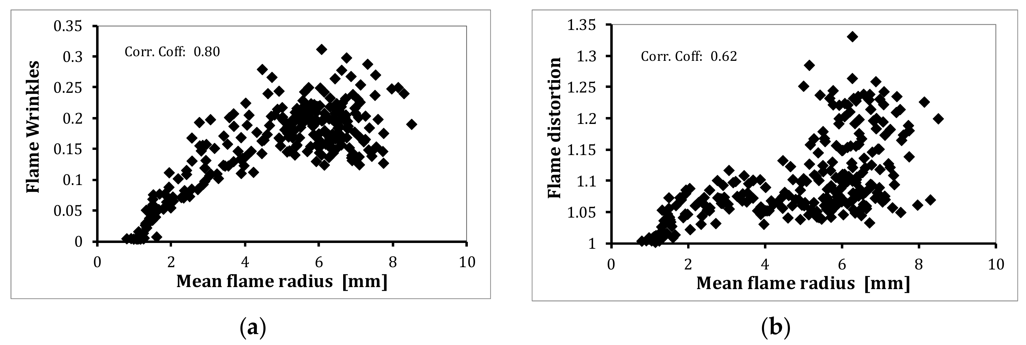
The flame growth rate, or expansion rate, measures the rate of change of the flame size, and is a function of all the flame parameters discussed earlier. It was calculated from an average equivalence radius analyzed from the area of the flame boundary from 40 flame images. The image with an equivalence radius closer to the average was selected to represent the position. The formation of wrinkles on the flame surface increases the reaction surface area of the flame, which in turn increases the burn rate. As discussed earlier, the small-scale eddies, which are smaller than the flame size, are responsible for the wrinkle formation on flame surfaces. With the rise in the flame size, more eddies become smaller than the flame, and add their contribution to the wrinkling process. Hence, the growth of the flame causes it to interact with the surrounding turbulent flow, and results in a more wrinkled surface. Therefore, the level of wrinkles increases with the flame size, as confirmed by the results shown in
Figure 14a. Flame distortion, on the other hand, did not seem significant until the flame grew to more than 5 mm in radius, as shown in
Figure 14b. In the early stages of combustion, the distortion was mainly the result of flow effects that could be associated with large-scale flow interactions with the flame [
8]. Contact of the flame with a cooler surface, such as the spark electrodes, can partially quench the flame, which may also create flame distortion. It can be hypothesized that in the early combustion period when the flame is very small, the flame can be convected by the large eddies, rather than distorted, as also mentioned in [
6], and flame distortion is only significant at the late stages of combustion once the flame has grown in size.
The other parameter that might influence the flame growth rate is the displacement of the flame from the spark center. As shown in
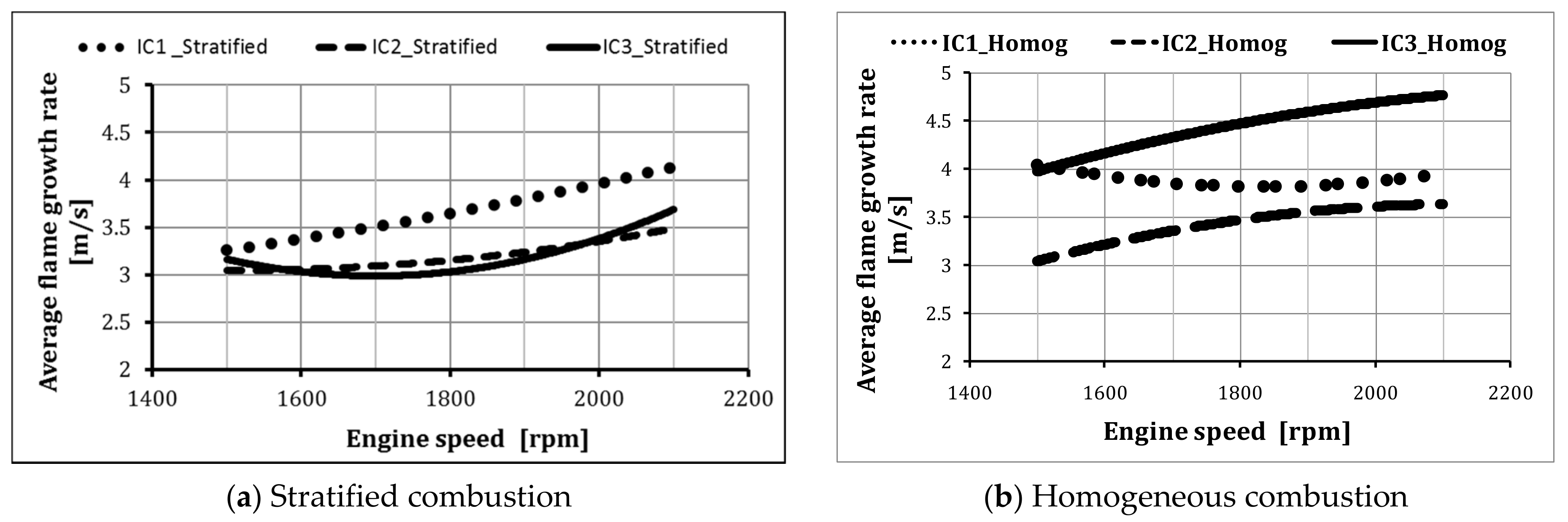
Figure 12, the small flame kernel, which had a radius of about 1 mm, was already convected away from its spark center at about 0.15 ms after the ignition timing. The flames captured at this time in case 1 (medium-tumble intake structure) were the farthest from the spark center, compared to the flames of the other two inductions. This was advantageous, as losses of such small flames due to contact with the spark plug were avoided, resulting in a faster flame growth rate in the development period, as depicted in
Figure 15a for stratified charge combustion. However, the homogeneous combustion mode, case 3 (high-swirl intake), produced the highest growth rate and more flame wrinkling capability, as depicted in
Figure 15b, while case 2 showed a lower rate of early flame growth, compared to the other two cases. This could be explained by a number of reasons: (a) the early flames of case 2 were initiated near the spark electrodes, resulting in heat losses to the electrodes and quenches of the flame surface; (b) a lower rate of flame distortion in case 2 homogeneous combustion; and (c) the level of flame wrinkles was also minimal.
It can be concluded from the above discussion that case 1 (medium-tumble intake) produced the highest early flame growth rate in the stratified combustion mode, as shown in
Figure 15a, in agreement with the findings of Gunasekaran and Ganesan [
27], while cases 2 and 3 showed almost similar growth rate characteristics in the stratified charge combustion mode.
The homogeneous charge mode, case 3 (high-swirl) produced the highest flame growth rate, while case 2 (medium-swirl) demonstrated the lowest rate, as shown in
Figure 15b. It was also observed that case 3, in the homogeneous charge, had the fastest growing flame of all cases in the development period, and the rate increased much more with engine speeds, while case 1 exhibited almost no variation with changes in engine speed. The result could not be compared with gasoline. The only comparison of the flame distortion of gasoline and
n-butanol in DI spark-ignition engines is available in the literature [
21].


 ,
, 


