


Abstract
This paper presents a design approach for the configuration synthesis of series-parallel hybrid transmissions with eight-bar mechanisms. The final design consists of 54 mechanisms with eight members and twelve joints including a simple planetary gear train (PGT) and a double planet PGT. Then, by using the techniques of power and clutch arrangements, new series-parallel hybrid transmissions are synthesized. The power arrangement process generates 97 clutchless hybrid systems. The clutch arrangement process generates 100 corresponding series-parallel transmissions. To demonstrate the feasibility of the synthesized configurations, a new hybrid transmission is selected as an example to analyze the working principle with operation modes and power flow paths.
1. Introduction
A series-parallel hybrid transmission system is a type of hybrid transmission system that uses a planetary gear train (PGT) to change the power flow paths of two power sources such as an internal combustion engine and an electric machine. The series-parallel system can operate in both series and parallel modes, and thus inherits the advantages of both systems, leading to optimized fuel efficiency and drivability based on the operating conditions of the vehicle.
Over more than two decades, many hybrid transmissions have been invented and developed [1,2,3,4,5,6,7,8,9,10]. The Prius, in which the hybrid configuration is called hybrid synergy drive (HSD), was Toyota’s first hybrid vehicle [11,12,13]. Then, Toyota came up with the second and third generations of HSD [14,15]. Most of these designs used a mechanism with two degrees of freedom (2-DoF) with one or two simple planetary gear trains (PGTs) without any clutch in the transmission. As a result, HSD is a simple configuration that makes it difficult to control series operation modes.
In 1996, General Motors developed a two-mode hybrid transmission including two PGTs and two electric motor/generators with two clutches and one brake [16,17,18], for running at both high speed and low speed. The clutches and brakes are engaged to control many flexible operation modes and improve vehicle performance and fuel economy [7]. Many other companies such as Honda, Renault, Nissan and Timken also use clutches and brakes for their transmissions [19,20,21].
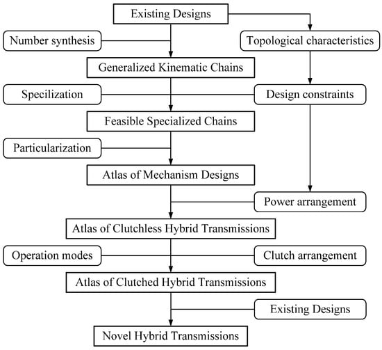
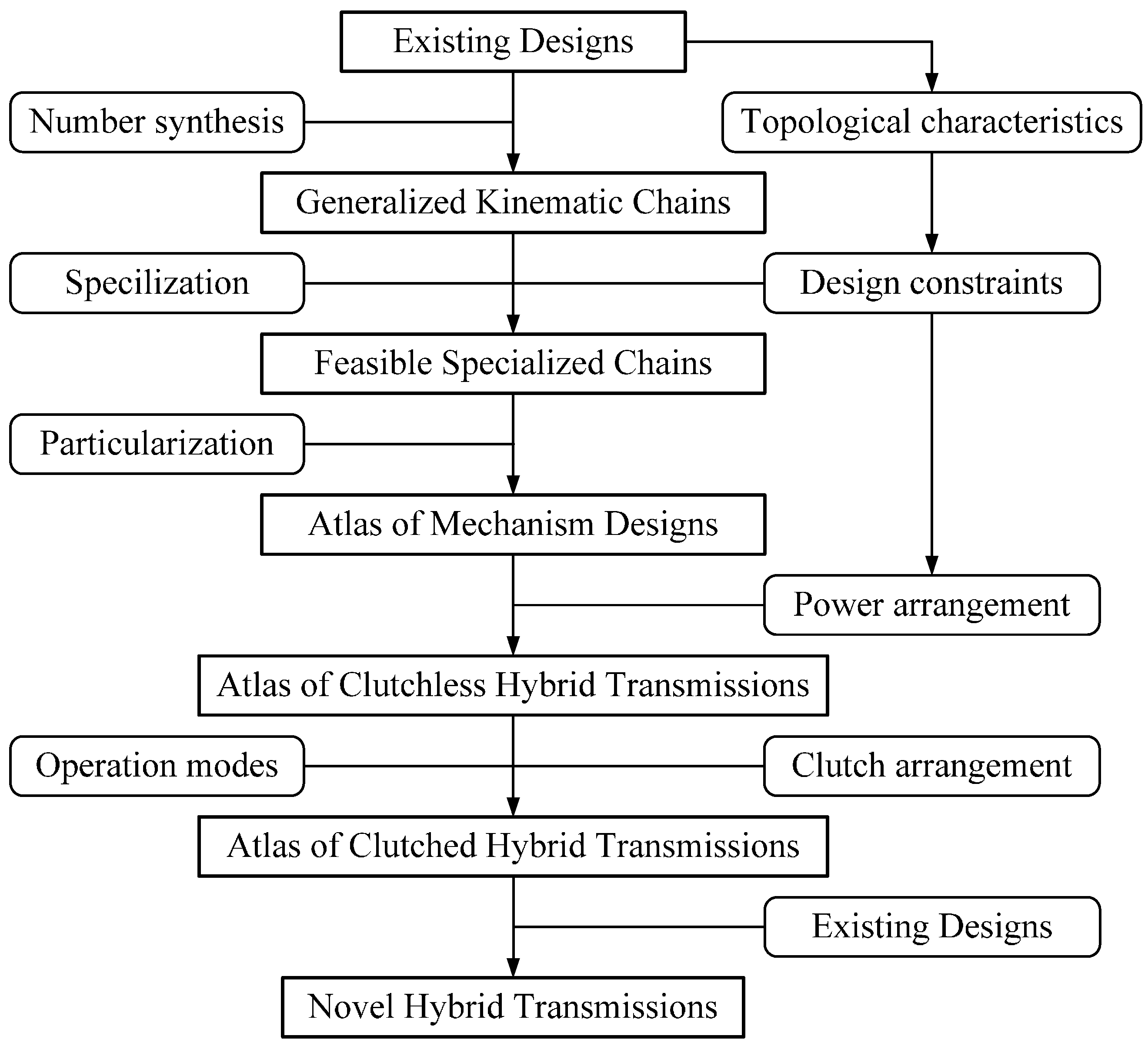
Many hybrid transmissions have been designed and analyzed based on traditional automatic transmissions [4,8,9], and only a few transmission configurations use double planet PGTs. Liu proposed a systematic design approach for 2-DoF PGTs with variably fixed interconnection methodology that is feasible with the PGT development process [22,23]. In addition, Ngo and Yan synthesized numerous feasible series-parallel hybrid transmission configurations with seven members and ten joints [24], based on an extension of Yan’s methodology [25,26] for the systematic generation of all new feasible configurations for hybrid electric vehicles (HEVs). This work proposes an approach for the configuration synthesis of novel series- parallel hybrid transmissions with eight-bar mechanisms, as shown in Figure 1.
Figure 1.
Procedure of configuration synthesis.
2. Existing Hybrid Transmissions
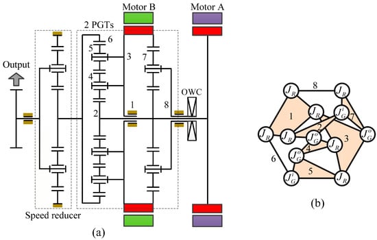
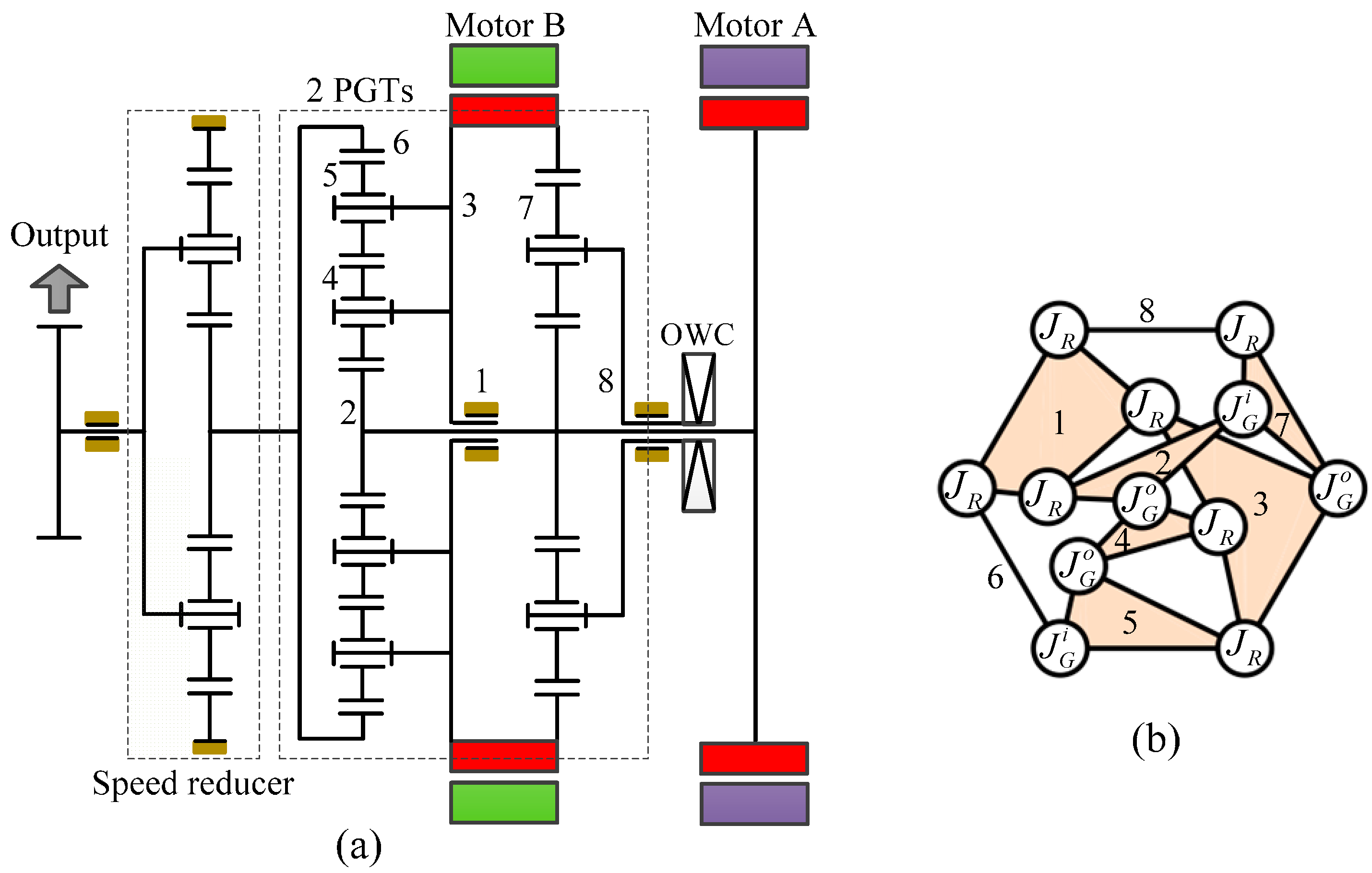
The procedure studies with identifying existing designs. NSK received the first assignment for a Japanese patent [27], which shows a PGT transmission including a double planet PGT and a simple PGT. Figure 2a,b describe the schematic diagrams of NSK’s hybrid transmission and the corresponding generalized kinematic chain (GKC), respectively.
Figure 2.
NSK’s hybrid transmissions: (a) Schematic diagram; (b) Corresponding GKC.
2.1. Topological Characteristics
By studying this existing design, the topological characteristics of the NSK transmission can be summarized as follows:
- It is a compound PGT mechanism with 2-DoF, which is a combination of a simple PGT and a double planet PGT.
- It has eight members including one ground link (member 1), one sun gear (member 2), two carriers (members 3 and 8), three planetary gears (members 4, 5 and 7) and one ring gear (member 6).
- It has twelve joints, consisting of seven revolute joints (JR) and five gear joints (JG) in which three external gear joints () and two of the gear joints are internal gear joints ().
- It has four separated links adjacent to the ground link.
A planetary transmission with 2-DoF must satisfy the following characteristics [25]:
where, NJ, NJR, NJG, and NL denote the numbers of joints, revolute joints, gear joints, and members, respectively.
2.2. Operation Modes
Mi et al. [7] presented the operation modes of a series-parallel hybrid system based on the vehicle operating conditions which show how the system works and what the status of each input and output source is. The six basic operating modes are:
- Motor alone mode: the motor alone drives the vehicle in the forward or backward direction using energy provided by the battery when the battery is at the high level.
- Engine alone mode: when the power demand is moderately high (e.g., during highway cruise control), the transmission shifts to the engine alone mode to further improve fuel efficiency.
- Combined power mode: when the power demand or required for heavy load or high-speed acceleration, the transmission shifts into power mode in which the engine is turned on together with the motor to provide additional power to drive the vehicle.
- Power split mode: when the power demand is low but the engine still must turn on, part of engine power is converted into electricity by the motor or generator to charge the battery and the remaining engine power drives the vehicle.
- Regenerative braking mode: the electric motor is operated as a generator to convert kinetic energy from the vehicle’s braking process into electrical energy, which is stored in the battery.
- Stationary charging mode: the engine drives the generator to charge the battery when the vehicle is at a standstill, and the battery is low.
Series-parallel hybrid systems inherit the advantages of both series and parallel systems to improve hybrid system performance. A control system is designed to control the switching between these systems to optimize vehicle performance.
Based on the analysis of the existing designs, the operation characteristics of the output and the inputs including the engine, the motor and the generator at each operation mode are concluded. In most hybrid systems, two couples (motor and output, and engine and generator) are located on the same simple PGT. In addition, since the motor speed is high and high torque is needed to move the vehicle in electric vehicle mode (motor alone mode), the motor speed transmitted to the output shaft must be reduced to provide high torque to the output shaft at low vehicle speed. Similarly, the generator normally works at the higher speed than that of the engine, and thus the speed of the engine is equal to or lower than the speed of the generator when the simple PGT is at 1-DoF. These characteristics are useful for concluding of the design constraints of inputs/output locations in a new system.
3. Generalized Kinematic Chains
Generalization transforms the schematic diagram of existing designs, which include various types of members and joints, into its corresponding GKCs based on a set of generalization rules [25]. For the NSK design shown in Figure 2a, the generalization process is carried out as follows (Figure 2b):
- Since the fixed ground link (member 1) is adjacent to four members (members 2, 3, 6, and 8) by four revolute joints, and it is released and generalized into quaternary link 1 (a link with four joints).
- Since the sun gear (member 2) is adjacent to two planetary gears (members 4 and 7) and the ground link, and it is generalized into ternary link 2 (a link with three joints).
- Since carrier (member 3) is adjacent to three planetary gears (members 4, 5 and 7) and the ground link (member 1), and it is generalized into quaternary link 3.
- Since the planet gear (member 4) is adjacent to two gears (members 2 and 5) and the carrier (member 3), and it is generalized into ternary link 4.
- Since the planet gear (member 5) is adjacent to two gears (members 4 and 6) and the carrier (member 3), and it is generalized into ternary link 5.
- Since the ring gear (member 6) is adjacent to a planet gear (member 5) and the ground link (member 1), and it is generalized into binary link 6 (a link with two joints).
- Since the planet gear (member 7) is adjacent to two gears (members 2 and 3) and the carrier (member 8), and it is generalized into ternary link 7.
- Since the carrier (member 8) is adjacent to a planetary gear (member 7) and the ground link (member 1), and it is generalized into binary link 8.
The corresponding GKC shown in Figure 2b has eight links and twelve joints. For simplicity and applicability to practical applications, only GKC with eight members are dealt with in this paper. Based on Equations (1)–(3), PGTs with eight members have twelve joints (seven revolute joints and five gear joints). According to the number synthesis of GKCs, there are 406 GKCs for mechanisms with eight members and twelve joints [25].
4. Specialized Chains
Feasible specialized chains are identified from GKC subject to design constraints.
4.1. Mechanism Constraints
4.1.1. Ground Link (Member 1):
- There must be one fixed link as the ground link.
- The ground link must be at least a quaternary link adjacent to binary links.
4.1.2. Planet Gear (Members 4, 5 and 7):
- A planet gear must not be adjacent to the ground link.
- There is no three-bar loop formed by any link adjacent to a planet gear, a binary link, and the ground link.
- Each planet gear must have just one carrier.
- Two planet gears (members 4 and 5) always adjacent to each other.
4.1.3. Carrier (Members 3 and 8):
- Carrier of the double planet PGT (member 3) always adjacent to member 4 and 5 and the ground link (member 1).
- In order to maintain the center distance between two or more planet gears in series, they must share a common carrier.
4.1.4. Sun and Ring Gears (Members 2 and 6):
- There must be at least one sun (ring) gear in a simple or double planet PGT.
- The sun (ring) gear must be adjacent to both the ground link and a planet gear.
4.1.5. Revolute Joint (JR):
- There must be seven revolute joints.
- The joints between a planet gear and its carrier, the ground link and a binary link must be revolute joints.
4.1.6. Gear Pair (JG):
- There must be five gear joints, namely three external gear joints () and two internal gear joints ().
- The joint between a planet gear and a ring (sun) gear must be a gear joint.
4.2. Inputs/Output Constraints
4.2.1. Output (O)
- One member of compound PGT must be connected to the output shaft.
- The output must be connected to a ring gear or planetary carrier of a PGT in order to achieve high torque transfer when the motor drives the vehicle alone.
- The output and the motor must be on the same PGT set.
- In the PGT set, the motor speed must be faster than the speed of the output shaft if the third link is fixed.
4.2.2. Motor (M)
- One member of compound PGT must be connected to the motor shaft.
- The motor must be connected to a ring gear or a sun gear in order to achieve speed reduction and obtain higher torque at the output shaft.
- The motor must not be connected to a carrier in order to avoid excessive output speed.
4.2.3. Engine (E)
- One member of compound PGT must be connected to the engine shaft.
- The engine must be at least connected to a ring gear or planetary carrier in order to have high efficiency when the vehicle is at high speed.
- The engine and the generator must be on the same PGT set.
- In the PGT set, the generator speed must be faster than the speed of the engine when the third link is fixed.
4.2.4. Generator (G)
- One member of compound PGT must be connected to the generator shaft.
- The generator must be at least connected to a sun gear or a ring gear in order to achieve high speed during braking and regeneration.
4.3. Feasible Specialized Chains
Specialization is the process of assigning specific types of members and joints into the atlas of GKCs obtained above, subject to concluded design constraints. A specialized chain subject to design constraints is called a feasible specialized chain [25].
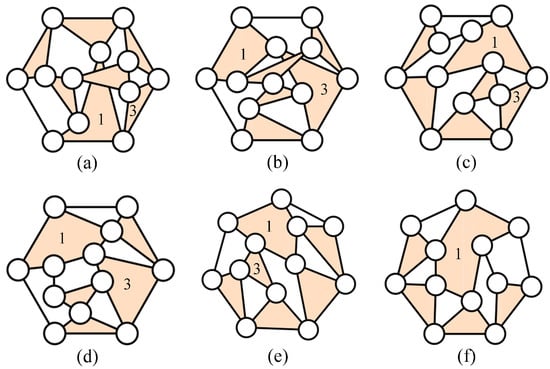
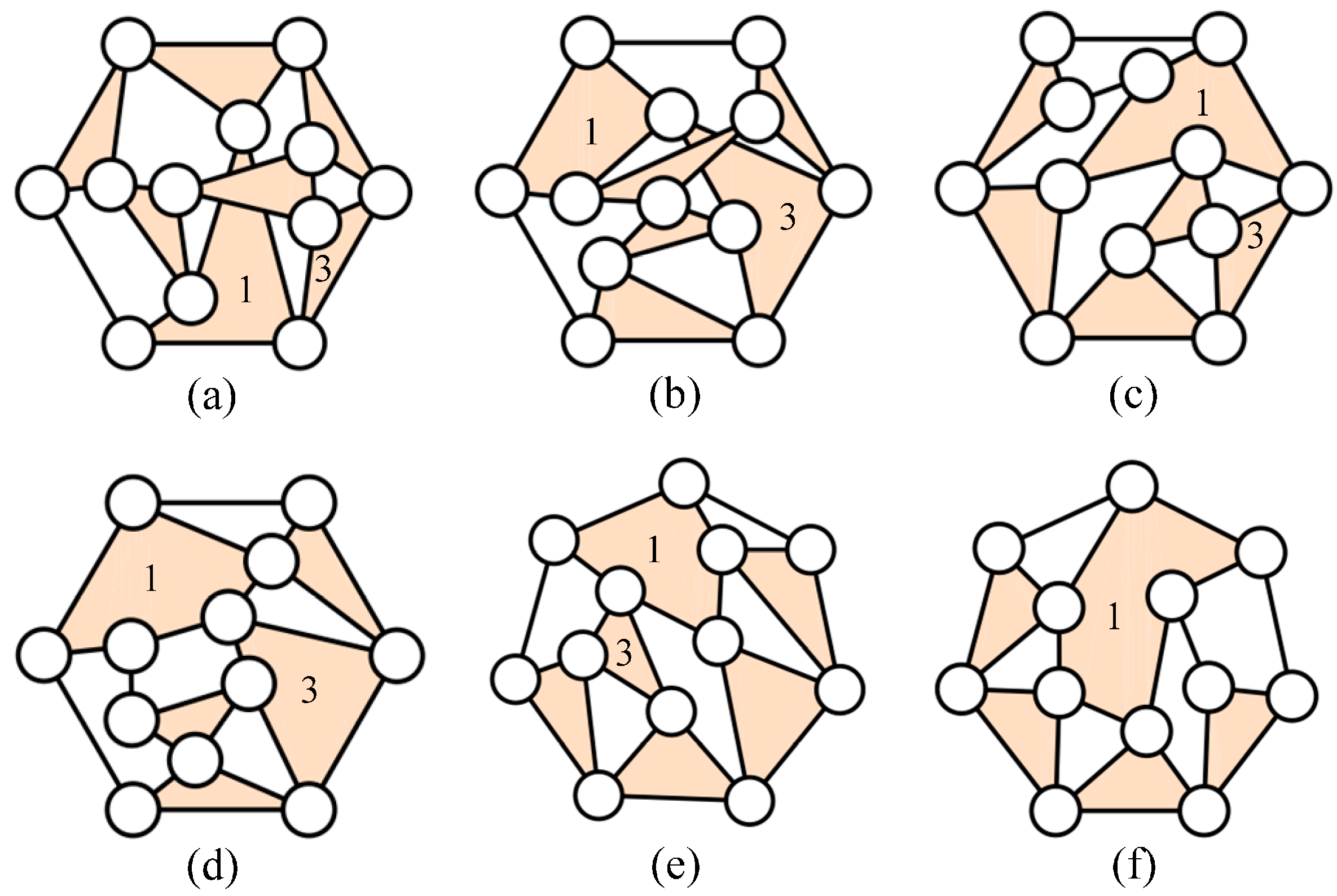
From the 406 available GKCs obtained above, only six GKCs with eight links and twelve joints satisfy the constraints of the ground link and the carrier of the double PGT, as shown in Figure 3. The corresponding feasible specialized chains subject to the design constraints above are identified according to the following steps:
Figure 3.
Specialized chains with identified ground link and the carrier of double PGT.
Step 1: Assign the ground link (member 1). For each GKC, the ground link is assigned, as shown in Figure 3.
Step 2: Assign the carrier of the double PGT. For each result in Step 1, the carrier of double PGT is assigned, as shown in Figure 3. Only the specialized chain is shown in Figure 3f cannot assign, because the carrier is adjacent the ground link in this case.
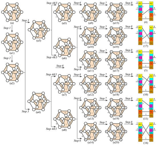
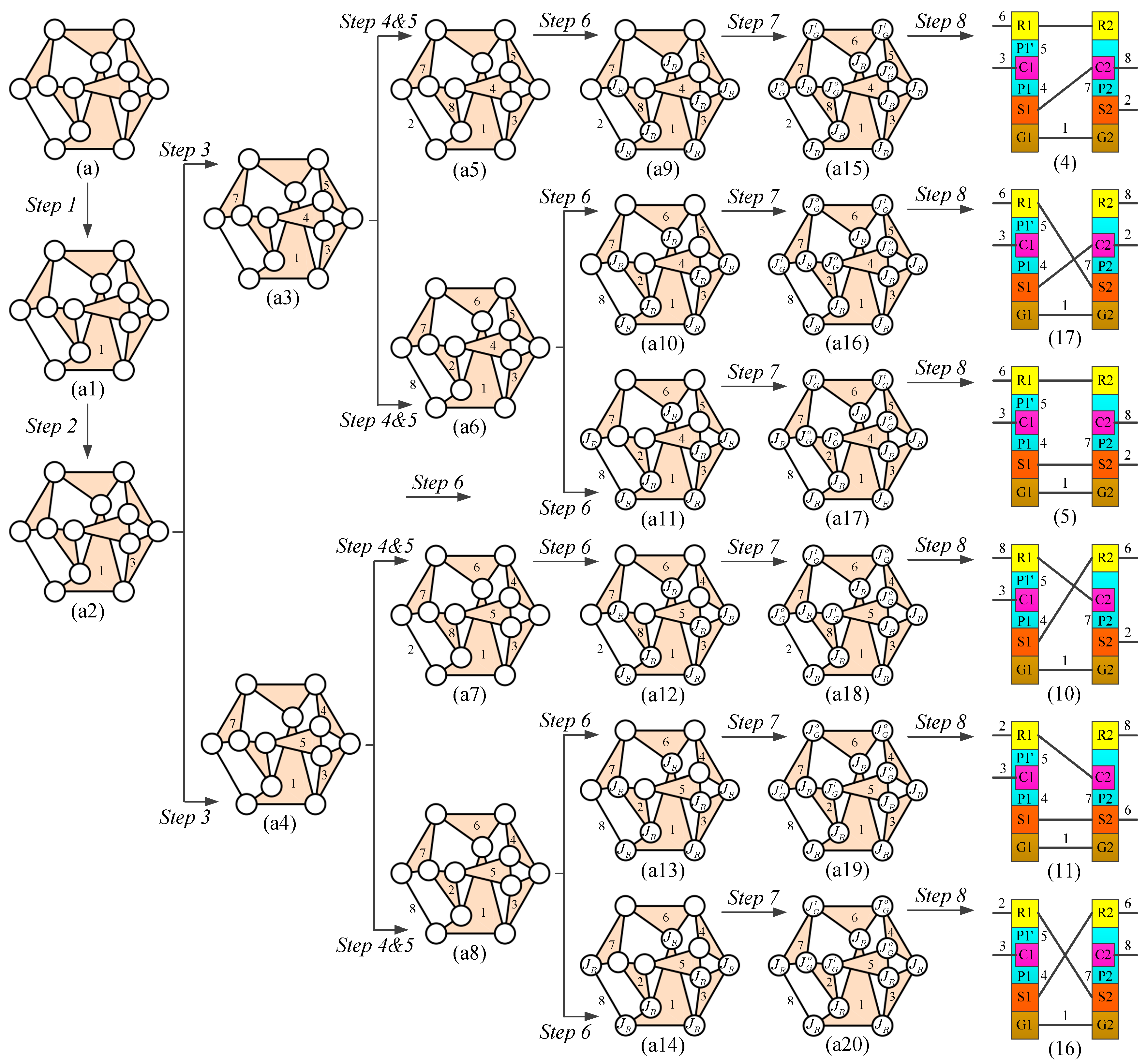
Step 3: Assign the planetary gear(s). For each result in Step 2, the planet gear(s) including members 4, 5 and 7 are assigned, as shown in Figure 4 ((a3) and (a4)).
Figure 4.
Process of specialization.
Steps 4 and 5: Assign the Sun (ring) gear and the remaining member(s). For each result in Step 4, the Sun (ring) gear is assigned. At the end of this step, the remaining member(s) is also assigned.
Step 6: Assign the revolute joints (JR). For each result in Step 5, the revolute joints are assigned. Six results are generated, as shown in Figure 4 ((a9) to (a14)).
Step 7: Assign the gear joints (JG). For each result in Step 6, the two external and two internal gear joints ( and ) are assigned. As a result, Six specialized chains are generated, as shown in Figure 4 ((a15) to (a20)).
Step 8: Transfer specialized chains to block diagrams. For each result in Step 7, Six specialized chains are transferred to the block diagrams, as shown in Figure 4 ((4), (5), (10), (11), (16), and (17)).
5. Atlas of Mechanism Designs
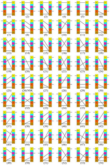
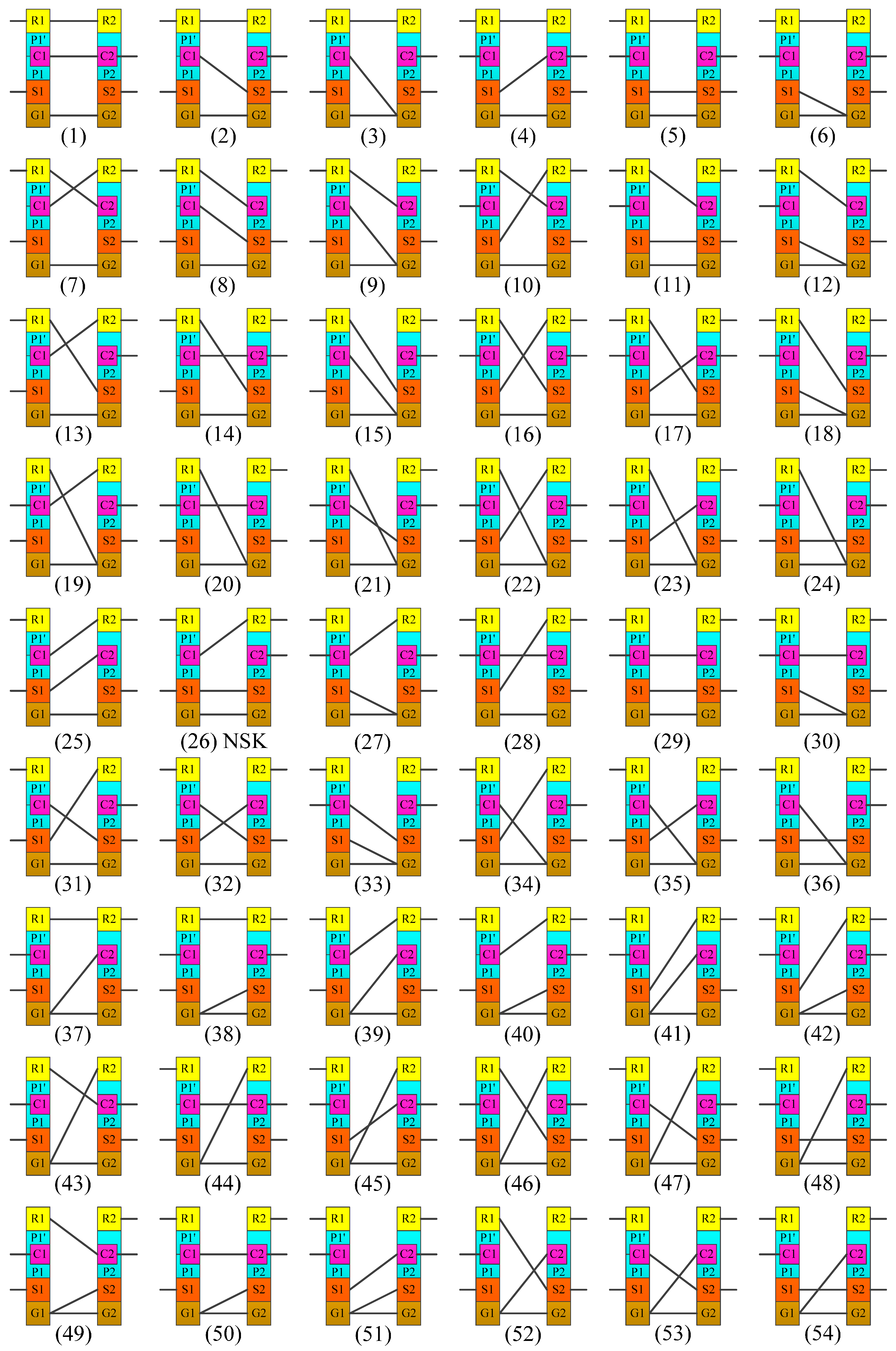
Particularization, the reverse graphical process of generalization, is used to regenerate corresponding schematic diagrams of the obtained feasible specialized chains [25]. Each feasible specialized chain obtained above is converted into its corresponding block diagram, as shown in Figure 5. There are 54 feasible specialized chains that correspond to 54 block diagram mechanisms. Figure 5 (26) shows the existing original design patented by NSK [27].
Figure 5.
Atlas of eight-bar PGTs for hybrid transmission mechanism.
6. Atlas of Clutchless and Clutched Hybrid Transmissions
Now, power arrangement, clutch arrangement, and operation modes are considered.
6.1. Power Arrangement
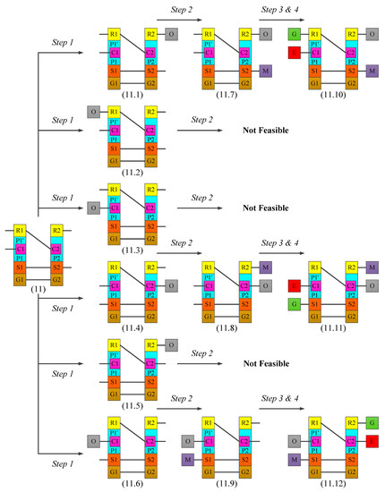
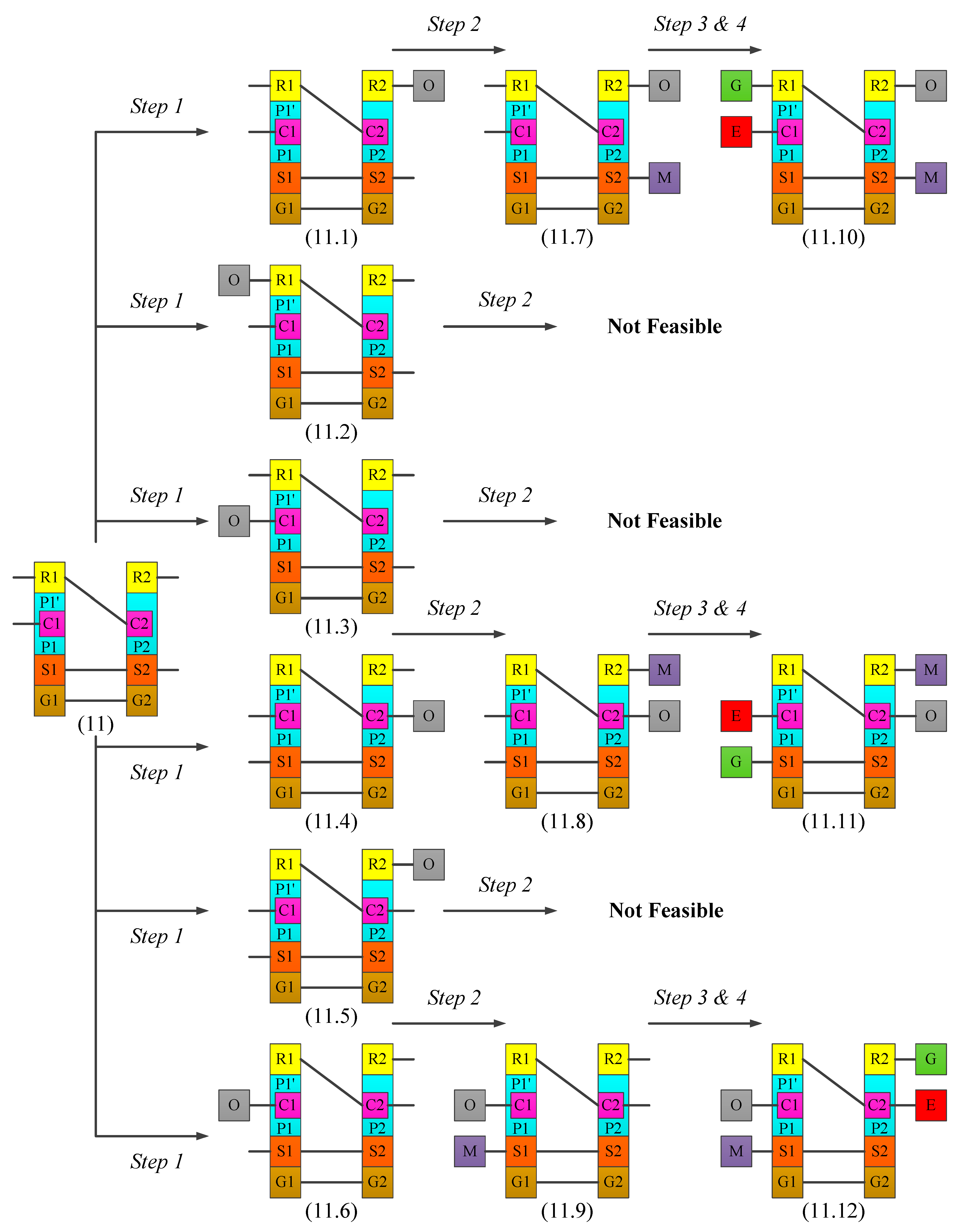
This step of the design process, the power arrangement process, aims to assign the inputs and output to the obtained mechanisms. The mechanism shown in Figure 5 ((11)) is randomly taken as an example to illustrate this process. Based on the design constraints for the inputs/output, the engine, motor, generator, and output are assigned to each mechanism according to the following steps:
Step 1: Assign the Output (O). For this mechanism, the generator is assigned. Six results are generated, as shown in Figure 6 ((11.1) to (11.6)).
Figure 6.
Process of power arrangement. E: engine; M: motor; G: generator; O: output shaft.
Step 2: Assign the Motor (M). For each result in Step 1, the motor is assigned. The assignment of the engine generates there results, as shown in Figure 6 ((11.7) to (11.9)).
Step 3 and Step 4: Assign the Engine (E) and the Generator (G). For each result in Step 2, the engine and the generator are assigned. The assignment of the engine and the generator generates three results, as shown in Figure 6 ((11.10) to (11.12)).
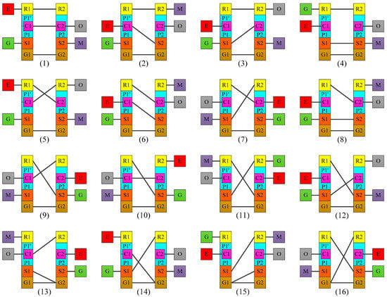
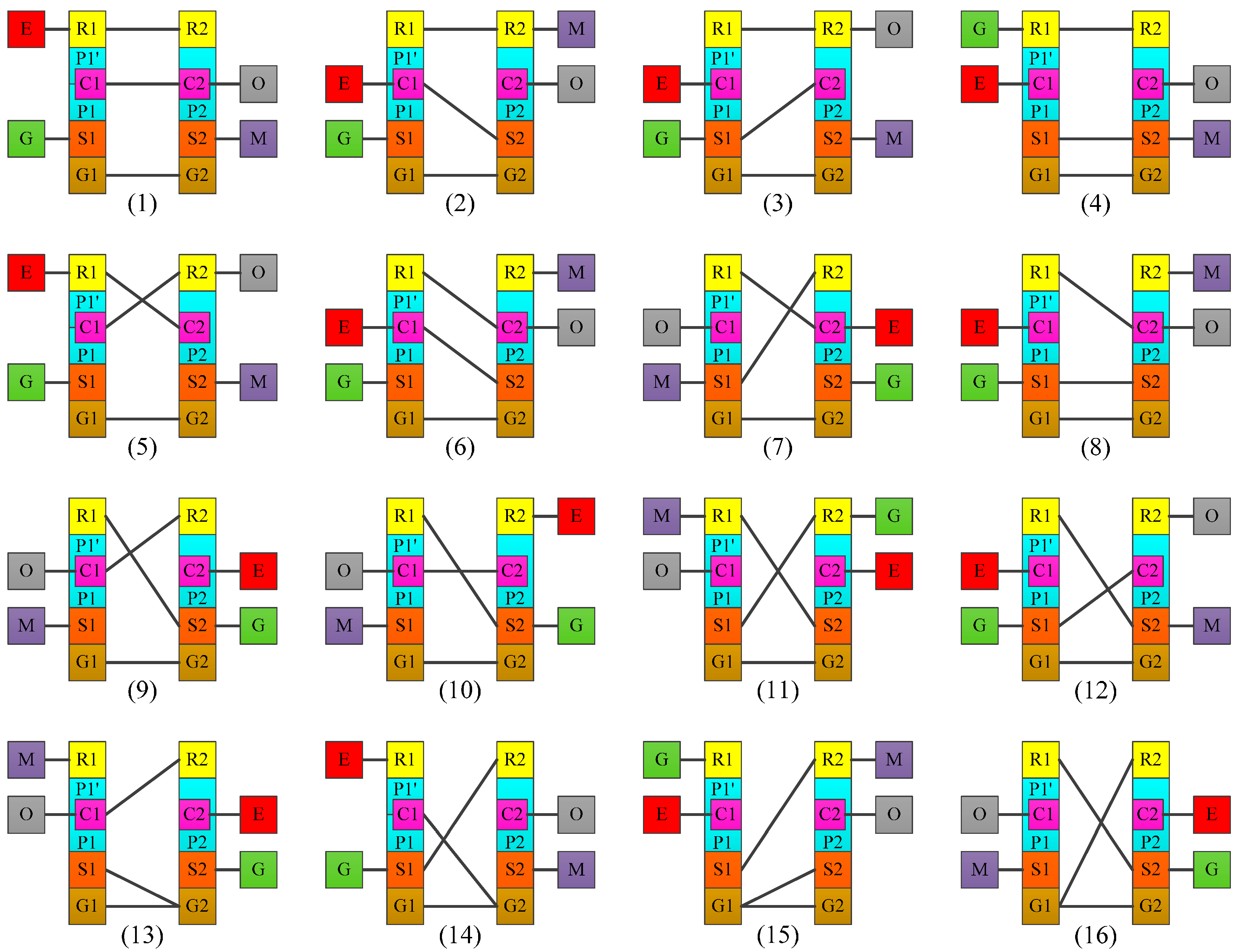
By applying this process to the other mechanisms, 97 systems with identified generator, engine, motor, and output are generated corresponding to the 54 obtained mechanisms. Since there are too many systems to be all listed here, Figure 7 shows only 16 of the systems as examples.
Figure 7.
Partial atlas of hybrid transmission systems without clutch. E: engine; M: motor; G: generator; O: output shaft.
6.2. Clutch Arrangement
Clutch arrangement is the process of assigning clutches and brakes to a system to control its operation modes subject to the required operation modes. It includes two main steps: the required operation modes and clutch arrangement.
6.2.1. Required Operation Modes
Based on the operation modes of existing designs and hybrid vehicle operation characteristics, the operation modes of a new design need to be decided in advance. Since the purpose of this paper is to develop new series-parallel hybrid transmission systems, the operation modes of new systems are listed in Table 1. The characteristics of power sources and the output are based on the operation modes presented above.
Table 1.
Proposed operation modes of a new series-parallel hybrid system.
6.2.2. Clutch Arrangement
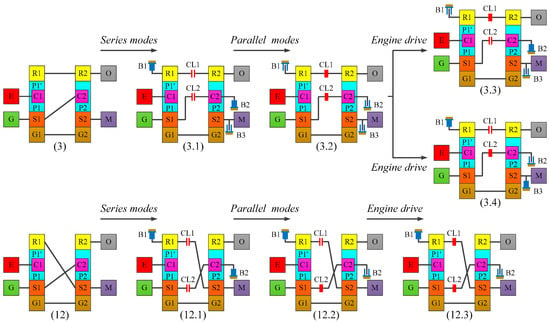
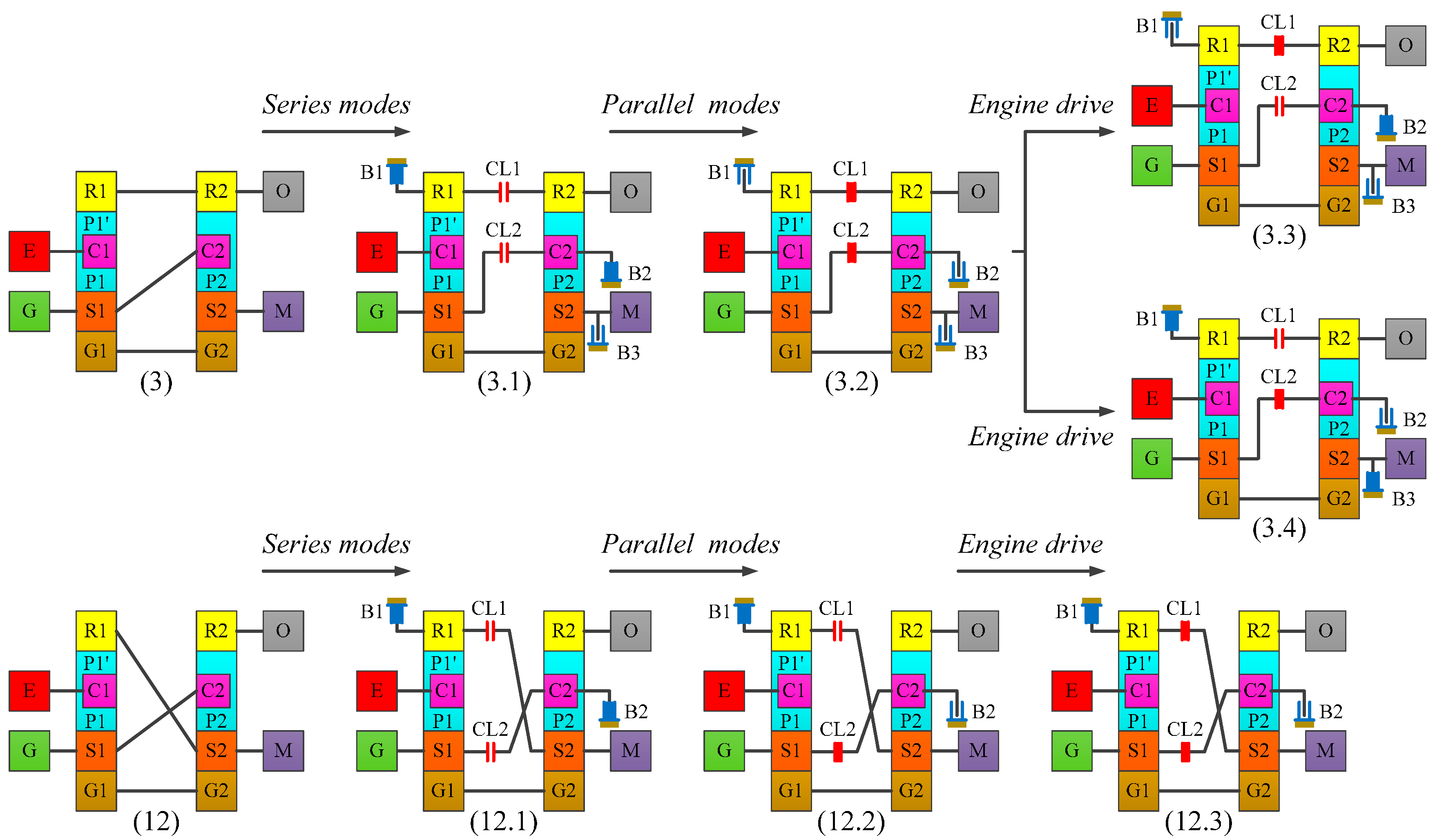
Based on the operation modes and status of power sources in each mode, the following process is used to add clutches and brakes to each system to achieve the required operation modes with the minimal number of clutches and brakes. The system shown in Figure 7 ((3) and (12)) are taken as examples to illustrate the clutch arrangement process, shown in Figure 8, respectively.
Figure 8.
Process of clutch arrangement. E: engine; M: motor; G: generator; O: output shaft; CL: clutch; B: brake.
Step 1: Series hybrid electric vehicle (HEV) mode. In series mode, the engine cannot be connected to the output shaft, and thus the common link(s) that connects the two PGTs must be separated into two independent PGTs by the clutch (CL). In addition, if a PGT is a 2-DoF mechanism, a brake must be added, making a 1-DoF design. The addition of clutches and brakes generates two results, as shown in Figure 8 ((3.1) and (12.1)). These systems can also operate with one motor alone, regenerative braking, and engine start condition (electric vehicle mode).
Step 2: Parallel HEV mode. In parallel mode, the engine can be connected to the output shaft, and thus the systems become 2-DoF systems, the brakes are released, and the clutches are engaged to connect the two PGTs. No more clutches or brakes are added, as shown in Figure 8 ((3.2) and (12.2)). These systems can also operate under combined power or power split condition, as in CVT mode.
Step 3: Engine alone mode. Since engine drive mode is required, the system is operated as a 1-DoF system while the engine drives the vehicle. The addition of clutches and brakes generates three results, as shown in Figure 8 ((3.3), (3.4), and (12.3)).
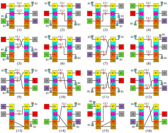
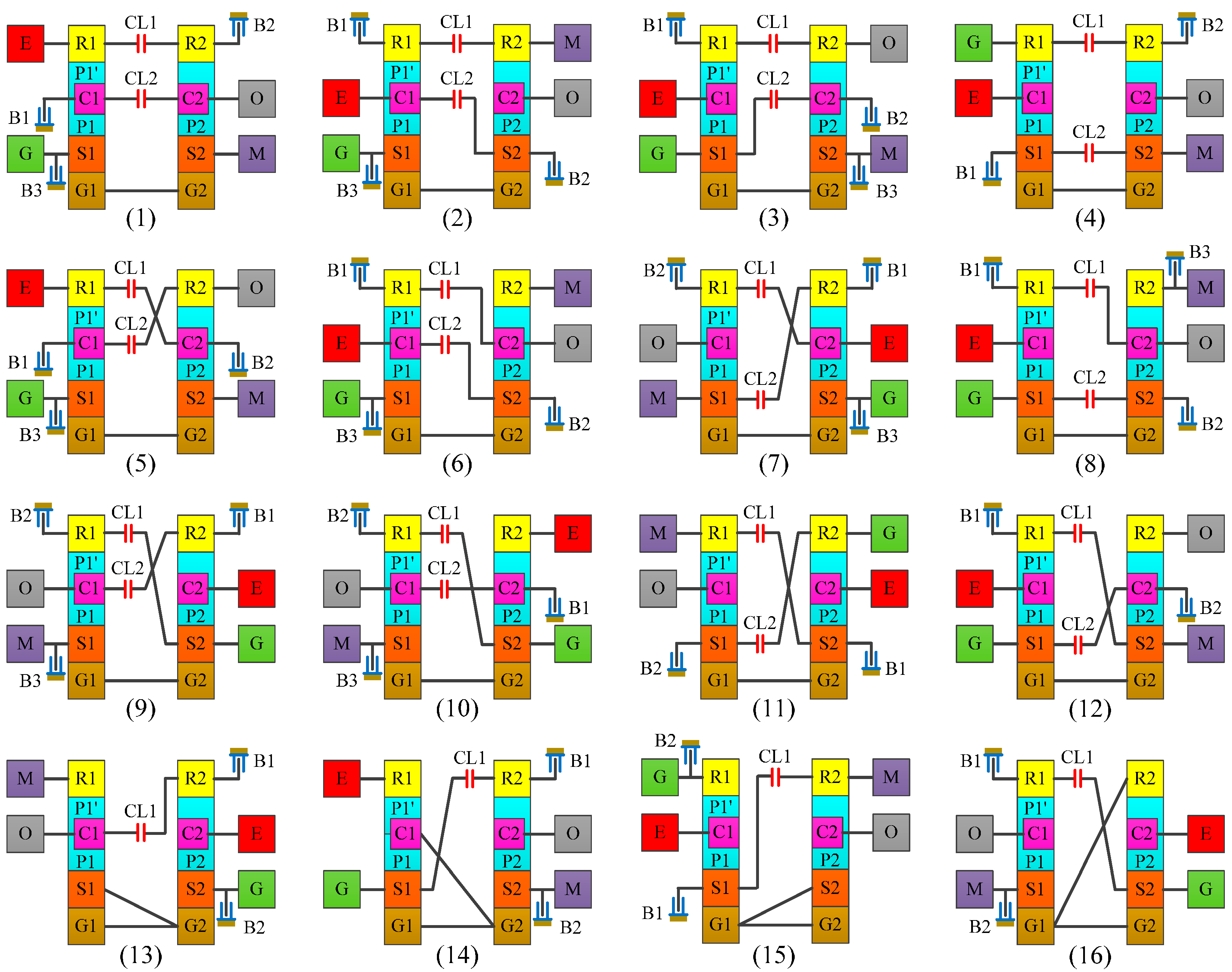
By applying this process to all systems, 100 clutched systems are synthesized for series-parallel hybrid transmissions. There are too many systems to be all listed here; Figure 9 shows only 16 of the systems as examples.
Figure 9.
Partial atlas of series-parallel hybrid transmissions. E: engine; M: motor; G: generator; O: output shaft; CL: clutch; B: brake.
7. Analysis of a New Series-Parallel Hybrid Transmission
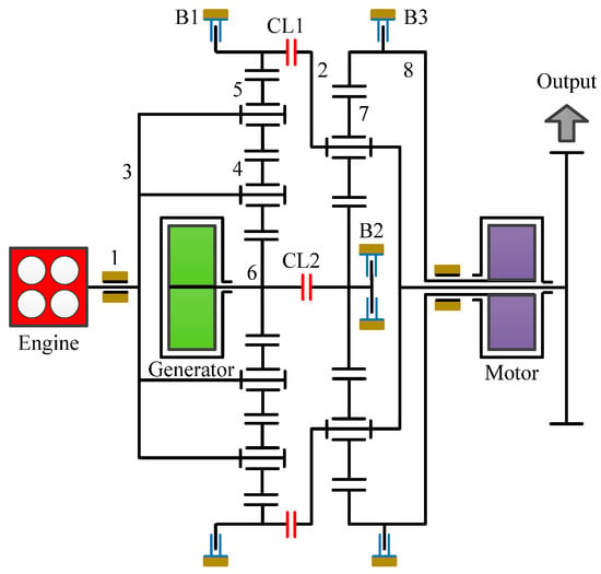
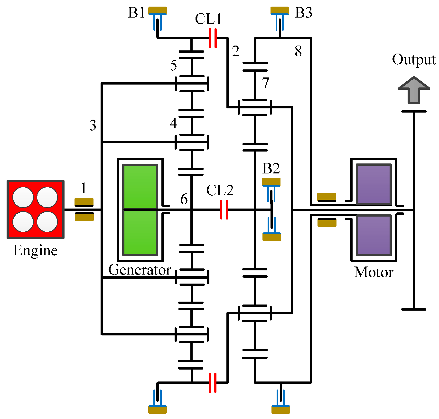
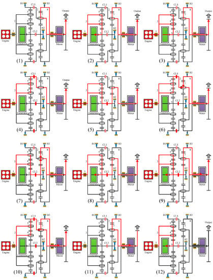
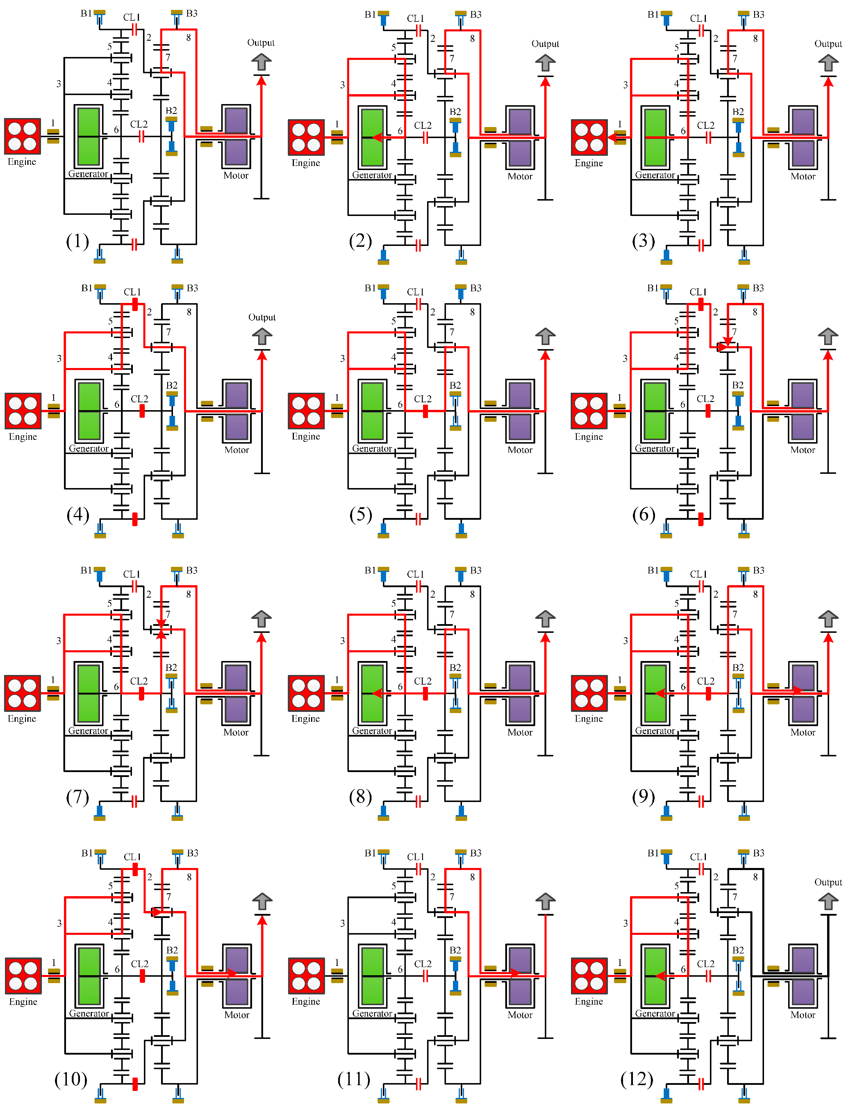
To demonstrate the feasibility of the synthesized hybrid transmissions, the design is shown in Figure 9 (8) is selected as a numerical example to show the operation modes and power flow analysis of a new system, as shown in Figure 10. The operation modes are shown in Figure 11, are divided into twelve possible clutching conditions as listed in Table 2, where an “x” indicates that the corresponding brake or clutch is engaged.
Figure 10.
A novel series-parallel hybrid transmission.
Figure 11.
Operation modes of the novel series-parallel hybrid transmission.
Table 2.
Operation modes and clutching conditions.
8. Conclusions
Through the study of existing hybrid transmission designs, an investigation of the system operation characteristics, the design constraints of mechanisms and inputs/output of hybrid transmissions is concluded. By applying the systematic design approach, the feasible mechanisms for the hybrid transmission configurations are synthesized. Then, the mechanisms are used for synthesizing clutchless and clutched hybrid transmissions by using the techniques of power arrangement and clutch arrangement. As a result, 54 compound PGTs are systematically synthesized for hybrid transmission by using the creative design techniques, 97 and 100 clutchless and clutched series-parallel hybrid transmissions are synthesized, respectively. The design constraints and desired operation modes decided in advance are flexible. Since some of the operation modes are required, and some of them are flexible choices, the design process generates different systems.
Acknowledgments
This work was supported by the Ministry of Science and Technology (Taiwan, R.O.C.) under Grant MOST 104-2221-E-006-059-MY3.
Author Contributions
The paper was a collaborative effort between the authors. The authors contributed collectively to the theoretical analysis, design, synthesis, and manuscript preparation.
Conflicts of Interest
The authors declare no conflict of interest.
References
- Berman, B.; Gelb, G.H.; Richardson, N.A.; Wang, T.C. Power Train Using Multiple Power Sources. U.S. Patent 3,566,717, 2 March 1971. [Google Scholar]
- Wong, Y.S.; Chau, K.T. Overview of power management in hybrid electric vehicles. Energy Conv. Manag. 2002, 43, 1953–1968. [Google Scholar]
- Ehsani, M.; Gao, Y.; Miller, J.M. Hybrid electric vehicle: Architecture and motor drives. Proc. IEEE 2007, 95, 719–728. [Google Scholar] [CrossRef] [Scilit]
- Tsai, L.W.; Schultz, G.; Higuchi, N. A novel parallel hybrid transmission. ASME J. Mech. Des. 2001, 123, 161–168. [Google Scholar] [CrossRef] [Scilit]
- Schulz, M. Circulating mechanical power in a power-split hybrid electric vehicle transmission. Proc. Inst. Mech. Eng. Part D J. Automob. Eng. 2004, 218, 1419–1425. [Google Scholar] [CrossRef] [Scilit]
- Zhang, Y.; Lin, H. Performance modeling and optimization of a novel multi-mode hybrid powertrain. ASME J. Mech. Des. 2006, 128, 79–89. [Google Scholar] [CrossRef] [Scilit]
- Mi, C.; Masrur, M.; Gao, W.Z. Hybrid Electric Vehicle: Principles and Applications with Practical Perspectives; John Wiley & Sons: Hoboken, NJ, USA, 2011. [Google Scholar]
- Chen, L.; Zhu, F.; Zhang, M.; Huo, Y.; Yin, C.; Peng, H. Design and analysis of an electrical variable transmission for a series-parallel hybrid electric vehicle. IEEE Trans. Veh. Technol. 2011, 60, 2354–2363. [Google Scholar] [CrossRef] [Scilit]
- Zhu, F.; Chen, L.; Yin, C. Design and analysis of a novel multimode transmission for a HEV using a single electric machine. IEEE Trans. Veh. Technol. 2013, 62, 1097–1110. [Google Scholar] [CrossRef] [Scilit]
- Esmail, E.L. Hybrid transmission for mobile robot. ASME J. Mech. Des. 2012, 134, 021001. [Google Scholar] [CrossRef] [Scilit]
- Yamaguchi, J. Toyota readies gasoline/electric hybrid system. Automot. Eng. 1997, 105, 55–57. [Google Scholar]
- Nagasaka, A.; Nada, M.; Hamada, H.; Hiramatsu, S.; Kikuchi, Y.; Kato, H. Development of the hybrid/battery ECU for the Toyota hybrid system. In Proceedings of the SAE 1998 International Congress & Exposition, Detroit, MI, USA, 23–26 February 1998. [Google Scholar]
- Takasaki, A.; Mizutani, T.; Kitagawa, K.; Yamahana, T.; Odaka, K.; Kuzuya, T.; Mizuno, Y.; Nishikawa, Y. Development of new hybrid transmission for 2009 Prius. In Proceedings of the EVS24 International Battery, Hybrid Fuel Cell Electric Vehicle Symposium, Stavanger, Norway, 13–16 May 2009. [Google Scholar]
- Hata, H.; Kojima, M.; Adachi, M.; Shimizu, T. Power Transmission System. U.S. Patent 7,081,060, 20 September 2006. [Google Scholar]
- Nagamatsu, S. Power Transmission Apparatus of Hybrid Vehicle. U.S. Patent 8,142,317, 27 March 2012. [Google Scholar]
- Zhang, D.; Chen, J.; Hsieh, J.; Rancourt, J.; Schmidt, M.R. Dynamic modeling and simulation of two-mode electric variable transmission. Proc. Inst. Mech. Eng. Part D J. Automob. Eng. 2001, 215, 1217–1223. [Google Scholar] [CrossRef] [Scilit]
- Grewe, T.; Conlon, B.; Holmes, A. Defining the General Motors 2-mode Hybrid Transmission. Available online: http://documents.epfl.ch/users/f/fr/froulet/www/Hybrid/HybridVehiclessession5-1.pdf (accessed on 19 July 2017).
- Ahn, K.; Cho, S.; Lim, W.; Park, Y.I.; Lee, J.M. Performance analysis and parametric design of the dual-mode planetary gear hybrid powertrain. Proc. Inst. Mech. Eng. Part D J. Automob. Eng. 2006, 220, 1601–1614. [Google Scholar] [CrossRef] [Scilit]
- Higuchi, N.; Sunaga, Y.; Tanaka, M.; Shimada, H. Development of a new two-motor plug-in hybrid system. SAE Int. J. Alt. Powertr. 2013, 2, 135–145. [Google Scholar] [CrossRef] [Scilit]
- Lehongre, C. Hybrid Engine Transmission Unit Comprising a Double Planetary Gear Train. U.S. Patent 6,468,175, 22 October 2002. [Google Scholar]
- Ai, X.; Mohr, T.W.; Anderson, S. An electromechanical infinitely variable speed transmission. In Proceedings of the SAE 2004 World Congress & Exhibition, Detroit, MI, USA, 8–11 March 2004. [Google Scholar]
- Liu, J. Analysis of Vehicle Transmission System; National Defense Industry Press: Beijing, China, 1998. [Google Scholar]
- Liu, J.; Peng, H. A systematic design approach for two planetary gear split hybrid vehicles. IEEE Veh. Syst. Dyn. 2010, 48, 1395–1412. [Google Scholar] [CrossRef] [Scilit]
- Ngo, H.T.; Yan, H.S. Configuration synthesis of series-parallel hybrid transmission. Inst. Mech. Eng. 2015, 230, 664–678. [Google Scholar] [CrossRef] [Scilit]
- Yan, H.S. Creative Design of Mechanical Devices; Springer: Berlin, Germany, 1998. [Google Scholar]
- Lin, J.L.; Yan, H.S. Reconstruction designs of the lost structures of the Antikythera mechanism with two degrees of freedom. ASME J. Mech. Rob. 2014, 6, 031016. [Google Scholar] [CrossRef] [Scilit]
- Gunji, D.; Matsuda, Y.; Kimura, G. Wheel Hub Motor. U.S. Patent 8,758,178 B2, 24 June 2014. [Google Scholar]

© 2017 by the authors. Licensee MDPI, Basel, Switzerland. This article is an open access article distributed under the terms and conditions of the Creative Commons Attribution (CC BY) license (http://creativecommons.org/licenses/by/4.0/).