Review

Opportunities and Challenges for Near-Field Wireless Power Transfer: A Review

by
Aqeel Mahmood Jawad
1,2,*,
Rosdiadee Nordin
1,
Sadik Kamel Gharghan
3,
Haider Mahmood Jawad
1,2 and
Mahamod Ismail
1
1
Department of Electrical, Electronic and Systems Engineering, Faculty of Engineering and Built Environment, Universiti Kebangsaan Malaysia, UKM Bangi, Selangor 43600, Malaysia
2
Department of Computer Communication Engineering, Al-Rafidain University College, Filastin, Baghdad 10064, Iraq
3
Department of Medical Instrumentation Techniques Engineering, Electrical Engineering Technical College, Middle Technical University (MTU), Al Doura, Baghdad 10022, Iraq
*
Author to whom correspondence should be addressed.
Energies 2017, 10(7), 1022; https://doi.org/10.3390/en10071022
Submission received: 20 May 2017 / Revised: 11 July 2017 / Accepted: 12 July 2017 / Published: 18 July 2017
(This article belongs to the Section L: Energy Sources)

Abstract

:
Traditional power supply cords have become less important because they prevent large-scale utilization and mobility. In addition, the use of batteries as a substitute for power cords is not an optimal solution because batteries have a short lifetime, thereby increasing the cost, weight, and ecological footprint of the hardware implementation. Their recharging or replacement is impractical and incurs operational costs. Recent progress has allowed electromagnetic wave energy to be transferred from power sources (i.e., transmitters) to destinations (i.e., receivers) wirelessly, the so-called wireless power transfer (WPT) technique. New developments in WPT technique motivate new avenues of research in different applications. Recently, WPT has been used in mobile phones, electric vehicles, medical implants, wireless sensor network, unmanned aerial vehicles, and so on. This review highlights up-to-date studies that are specific to near-field WPT, which include the classification, comparison, and potential applications of these techniques in the real world. In addition, limitations and challenges of these techniques are highlighted at the end of the article.

1. Introduction

Wireless power transmission (WPT) is a term that denotes many different technologies for transmitting electromagnetic energy through a physical electromagnetic field. WPT is not a new concept. In fact, several efforts have been conducted in the past decades to transfer energy wirelessly. The beginning of WPT dates back to 1868, when James Clerk Maxwell merged “Ampère’s circuital law” and “Faraday’s law” of induction. In addition, other experiments, observations, and mathematical models have been developed into the consistent theory that constitutes conventional electromagnetic theory. The Maxwell equations provide the keystone for current electromagnetics, including wireless energy transfer. In 1884, John Henry Poynting presented an electromagnetic field mathematical equation that can be used in contactless energy transfer [1,2]. In 1888, Heinrich Rudolf Hertz discovered radiowaves, confirming the forecast of electromagnetic propagation by Maxwell. Hertz’s experiments showed that electromagnetic waves could be produced in transmitter coils and wirelessly detected by a receiver coil [3]. In 1894, Hutin and Leblanc’s patented WPT system was used to supply an electric railway system [4]. Their system consists of a primary single wire that transmits power at 2 kHz along the railway track and several resonant receiver coils used at the secondary side.
From 1891 to 1904, the first significant innovation in WPT technology was accomplished by Nikola Tesla. Tesla’s experiments were conducted based on inductive coupling WPT using Tesla coils, which produces high alternating current (AC). Tesla demonstrated the wireless lighting of phosphorescent bulbs. In 1897, Tesla patented the “Tesla Tower” built in Colorado Springs. Three shining lamps were lit on this tower at a transfer distance of approximately 100 feet. The work of Tesla contributed to long-distance energy transfer based on radio communications. Brown [5] realized long-distance energy transfer thanks to the advancement of microwave technology in 1960. Later in 1964, Brown efficiently used a rectenna to convert electromagnetic waves into direct current (DC) power. In 1975, Brown introduced short-distance transfer of 475 W using microwaves at 54% DC to DC efficiency at Landmark. In 2007, a group of physicists from the “Massachusetts Institute of Technology” lit a 60 W light bulb 2 m away from the transmitting coil [6]. In 2012, the United States Department of Transportation realized the use of WPT for charging vehicles while moving on the highway [7]. The WPT research efforts between 2001 and 2013 are described briefly in [8]. According to [8], the four most active countries in research on WPT are the US, Japan, China, and South Korea. In 2015, the Nuclear and Quantum Engineering team at KAIST University adopted inductive coupling WPT to transfer energy to a distance of 3, 4 and 5 m with efficiencies of 29%, 16%, and 8%, respectively. This team transferred energy based on an oscillating frequency of 20 kHz in the transmitting coil.
WPT can be categorized into two types, namely, far-field and near-field WPT. Microwave energy transfer falls under the far-field category, in which a large amount of energy can be transmitted between two positions. A WPT system involves a transmitter unit that is connected to the main source of power or battery, which transforms the electrical power into an electromagnetic field. This field may be received by one or multiple receivers to convert it back into electrical power, to be used by the electrical load. On the transmitter side, the power signal and information are carried by the same radio frequency (RF) signal. The information can be recovered at the information receiver and the electromagnetic energy is recovered by the harvester section of the receiver to supply the power to the receiver [9]. The oscillator circuit of the transmitter converts the input power to the electromagnetic field that can be transmitted via the transmitter antenna or coupling systems. At the receiver side, similar coupling systems or antennas are used to alter the received electromagnetic field into electrical current that can be harvested to run the receiver devices [10].
Near-field WPT refers to the distance of transfer energy within the wavelength (λ) of the transmitter antenna. The near-field mechanisms can be categorized into four groups depending on the type of coupling technique used: (i) magnetic resonant coupling; (ii) inductive coupling; (iii) capacitive coupling; and (iv) magneto dynamic coupling. The most suitable methods are magnetic resonant coupling and inductive coupling because the amount of transfer power in capacitive coupling increases with the capacitance between the plates and frequency. Therefore, the total surface area of the capacitor will be increased and accordingly, the size will be large and high voltages on the capacitor plates are required.
In magnetodynamic coupling, two energy conversions occur, namely: (i) electrical to mechanical energy in the transmitter; and (ii) mechanical to electrical energy again in the receiver. This process makes magnetodynamic coupling less efficient relative to electrical conversion methods such as inductive coupling. However, the magnetic resonant coupling and inductive coupling methods are suitable for short and midrange distances and rely on the shape and size of the antenna or coil of the transmitter and receiver.
In the past few years, portable and wireless devices have become prevalent. This has resulted in a significant diversity of battery chargers on the market, which can be considered a serious problem [11]. Conventionally, charging these devices is performed based on wired technology that requires a wire connected to an electrical wall outlet. Charging can also be achieved wirelessly to achieve similar efficiency by using WPT technology [12]. WPT is a promising method to solve the particular power-charging problems ingrained in several wireless platforms [13]. When the electromagnetic energy (EM) is available, such as in a Tesla coil, WPT can be produced without a physical connection. Essentially, WPT ideas originated from “electrical-oriented” power transmission objectives for electromagnetic waves that have much lower frequencies than do optical and infrared ones. The potential of WPT has not yet been well realized, although four recent key technological features, namely: (i) high-density power devices; (ii) high-efficiency rectennas; (iii) innovative circuit architectures; and (iv) low-power integrated circuits (ICs), have been progressing at the research level [14].
Given the rapid development of mobile devices (e.g., mobile phones, laptops, Personal digital assistants (PDAs), and handheld devices) and sensor-based Internet of Things (IoT) applications, significant attention has been focused in the development of wireless power-charging techniques. These applications rely on the short-range inductive coupling of WPT. Previous studies include an effective detection technique for various charging devices and an electric charging strategy by finding correct receiving equipment [15,16]. A method called resonance coupling was proposed to extend WPT to mid-range operation [17]. This method relies on the physical conception that two resonators with identical frequency can efficiently receive power with reciprocity. In addition, utilization of an extra resonator as a repeater improves the power conveyance ability of the system, thus allowing the working range between transmitter and receiver coils can be extended [18,19]. However, for real-time applications, the distance over which the power transmission can be varied. The efficiency of WPT drops quickly when the air gap between the coils is changed or any axial misalignment between transmitter and receiver coils occurs [20]. Therefore, some studies, such as [21], have proposed a self-adjusting system to address the misalignment problem.
WPT techniques can be used to address the energy consumption problem in wireless sensor networks (WSNs). The WSN lifetime is limited by the battery capacity and they can only work for a limited amount of time. Several studies have emphasized different methods to prolong the lifespan of networks. Although these efforts have shown an improvement in WSN power consumption, their power consumption/lifespan remains a performance bottleneck and its feasibility is the key factor that impedes deployment in vast areas. Xie et al. [12] classified WPT into three categories, namely, magnetic resonant coupling, inductive coupling, and EM radiation. They presented the pros and cons of each category and discussed the opportunities to use WPT technology in WSNs. In their study, they concluded that EM radiation technology has some restrictions when used in WSNs. The first key concern is that omnidirectional radiation has poor efficiency in WPT. Second, it is sensitive to the presence of any obstacles between receiver and transmitter. Third, it poses a challenge to human safety. The research also found that magnetic resonant coupling technology is more appropriate for WSNs. Powering the sensor nodes in WSNs remains a challenge nowadays, even with developments in battery technology and energy efficient techniques. Inductive coupling only works efficiently over a short distance, but it can be expanded at further distances by using robust coupled magnetic resonances [22].

2. Related Review Works

In a review by Hui et al. [23], two-coil, three-coil, and relay and domino resonator WPT are covered. In addition, the effect of electromagnetic radiation on the human body is highlighted. The review suggested that the transfer efficiency of the two-coil WPT is appropriate for short-range rather than midrange applications. By contrast, the four coils WPT approach can be used to maximize the transfer distance. However, the transfer efficiency will be reduced and limited to 50%. Moreover, the relay or domino technique presents good system transfer distance and transfer efficiency in a situation, in which the relay coil is located between the source and load coils. Dai and Ludois [24] compared inductive coupling and capacitive coupling, which they used in small energy transfer gap applications. They reviewed these two types of WPT in terms of power level, operating frequency, transfer distance, transfer efficiency, and transmitter and receiver areas. Applications and limitations for both types were also emphasized. In addition, recommendations for selecting inductive coupling or capacitive coupling in small range systems are introduced.
Inductive and conductive charging of hybrid and electrical vehicles were reviewed by Yilmaz and Krein [25]. In addition, the present status and execution of battery charger, infrastructure, and charging power level for electrical vehicles were highlighted. The researchers classified vehicle charging systems into on-board and off-board types. Several infrastructure configurations and charger power levels were considered and compared in their review, depending on the charging time and position, the amount of power, suitability, equipment necessary, cost, and other factors. Kalwar et al. [26] briefly reviewed and compared several electrical vehicle charging systems and their deployment. They presented circuit investigation and characteristics of the inductive coupling power transfer and concentrations on the research development as regards the strategy for the charging coil, power level improvement, inductance topologies, and misalignment toleration. Through their review, they found that the implementation of the inductive coupling technique was conditioned on proper alignment, charging distance, and coil topology. In addition, a trade-off between transfer efficiency, distance, and charging pad size is essential for electrical vehicle applications.
Similar review papers can be highlighted that have adopted different issues related to electrical vehicles charging such as opportunities and challenges, sustainable performance, topology infrastructure of inductive coupling, milestones of improvements in charging vehicles based on inductive coupling techniques [27], dynamic and static vehicle charging [28], consideration for designing inductive coupling, and charging power levels [29].
Akhtar and Rehmani [30] presented energy-harvesting techniques to replenish the energy of WSNs, including WPT. The inductive coupling, magnetic resonant coupling, radio frequency, laser, and acoustic WPT techniques were emphasized with their applications, challenges, limitations, advantages and disadvantages, transfer efficiency, and future research trends.
Our review paper differs from the other reviews (listed in Table 1) in that our paper focuses on all the near-field WPT techniques, namely, magnetic resonant coupling, inductive coupling, and capacitive coupling. The paper also discusses WPT applications and performance metrics (i.e., energy transfer, operating frequency, transfer distance, transfer efficiency, and output power) through comparison with previous work in terms of limitations and challenges. Recently, the WPT has been used to replenish the batteries of implanted devices and medical sensors, in which battery change is impossible [12]. One potential application of WPT is charging wireless sensor nodes in WSNs because of the limited battery energy. For example, WPT can be used to improve the battery lifetime of an unmanned aerial vehicle (UAV), which is likely used in monitoring agricultural crops.
This paper presents a concise evaluation of recent advancements in WPT, and near-field WPT is specifically reviewed. The contribution of this review paper can be outlined as follows:
(i)
The near-field WPT techniques are critically reviewed for inductive coupling, magnetic resonant coupling, and capacitive coupling.
(ii)
Comparisons of our review paper with previous reviews are achieved based on types of near-field WPT, performance metrics, challenges, and applications.
(iii)
The performance metrics of near-field WPT are identified, which include transfer distance, transfer efficiency, output power, and operating frequency. In addition, the comparison between these metrics is presented.
(iv)
A taxonomy of near-field WPT is introduced to select the more efficient technique in terms of transfer distance and transfer efficiency.
(v)
Challenges and limitations are emphasized in terms of health and security, metallic element in the path of transferred power, and transfer distance and efficiency.

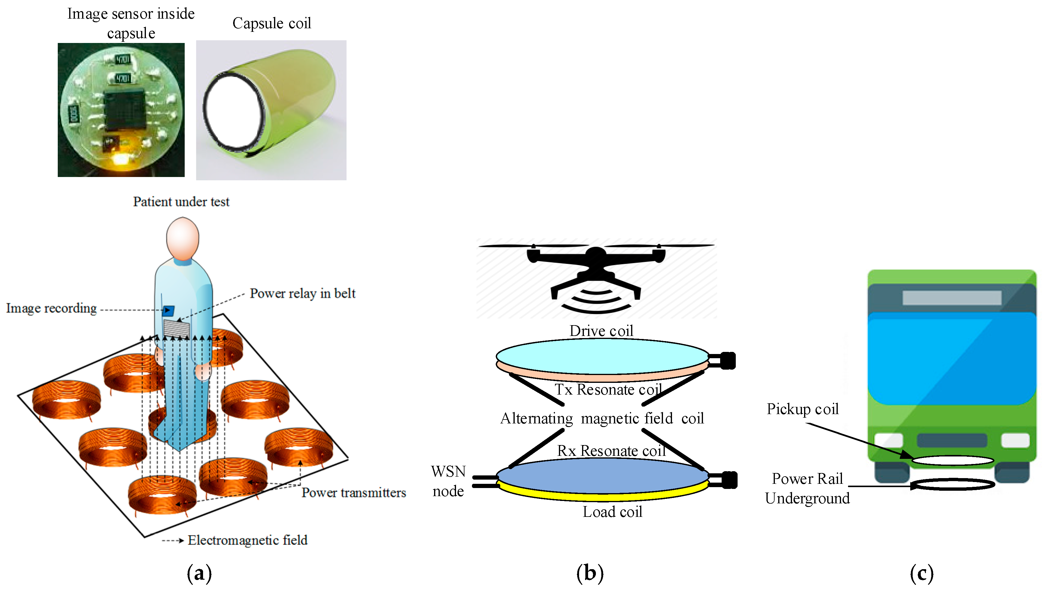
3. Wireless Power Transfer Applications

WPT can be used over a short range in offices and homes to charge different devices. Battery charging can be performed on a table or a desk for different electronic devices, such as smartphones, PCs, tablets, and audio players [35]. Special outdoor applications are also used, such as wireless charging for electric trams and vehicles; furthermore, power supply for running cars may be used [36,37]. In addition, WPTs can be used in medical applications as a power supply for a capsule endoscope for diagnosis gastroenterologists [38], as well as other devices implanted under the human skin, such as cardiac implants [39]. Tower and transmission lines can be inspected based on UAVs. The main task of the UAV is to inspect the transmission line via remote and rough terrain and forests, and at high altitudes. This is an important task because the transmission lines can supply power to hospitals, homes, industry, and others over long distances.
The main limitations of UAV are their endurance and range because of the limited battery capacity. UAV battery size cannot be increased because it would add extra weight, thereby becoming a limiting factor for flying. UAV batteries can be charged based on inductive coupling WPT to increase flight time or extend the UAV range that is used, for example, in surveillance or inspection. The energy of the UAV that inspects the high-voltage transmission line can be obtained from the electromagnetic field that is generated from the transmission line, in which the transmission lines operate as a long transmitting antenna [10]. Thus, the limitation of the UAV can be overcome based on the presented method. By contrast, using UAVs overcomes the limitations of the current inspection methods, which rely on manned helicopters; this is considered a risky operation and an expensive task. UAVs can also be used to transfer power to the ground nodes based on inductive coupling as presented in the studies [22,40] in which the transmitted coil is mounted on the UAV and the receiving coil is fixed on the sensor node.
WPT was used to recharge electric vehicle batteries rapidly to meet the extended working range [41]. Battery charging can be achieved during a temporary stop in stations based on receiving and transmitting coils, through the transmitting coil embedded in the roadway and receiving coil equipped on the bus or rail transit [42]. Yang et al. [43] proposed an energy harvesting approach that used a bicycle motion to acquire kinetic energy. Their experimental results disclosed that more than 6.6 mW of energy could be obtained under regular cycling situations. They concluded that the energy harvesting method could also produce electrical power uphill without increasing the mechanical work by the cyclist.
WPT is used in medical implantation applications to detect and treat diseases of the human body. Some tiny electronic devices are deployed outside or inside the body. These devices are power hungry and need continuous power to work properly for a long time. Chiu et al. [44] used the 402 MHz RF to stimulate the dorsal root ganglion. The external device can charge the implant device using inductive coupling that uses 1 MHz. Depending on the inductive coupling techniques, the implant device can be operated for six months. Inductive coupling WPT is used by Ha et al. [45], who employed an outside helical coil that induces a magnetic field in the coil implant inside the human arm. Consequently, a current will flow in the coil inside the human body. Therefore, the device inside the body can receive the energy from the outside coil. Furthermore, the WPT is presented by Sun et al. [46] for capsule endoscopy inspection. The proposed system was able to transfer the energy of 24 mW to the capsule over an air gap of 1 m with a power efficiency of 3.04%. Secure communication can be achieved based on encryption techniques to ensure safe exchange of information between transmitter and receiver. However, encryption techniques may consume a large amount of power because of high computational capacity, thereby leading to inefficient system energy, in which the energy of the communication system is considered a crucial issue. Consequently, power transfer and wireless information can be proposed to achieve two tasks; the first task ensures secure information transmission and the second ensures efficient WPT. When the received power is a potential eavesdropper, the enhancing power transfer efficiency by increasing the information power could result in loss of secrecy. Thus, a tradeoff between power transfer efficiency and information transmission security is necessary, as presented in [47]. WPT technology is already used widely and looking forward to be used in new applications in the near future, as illustrated in Figure 1.

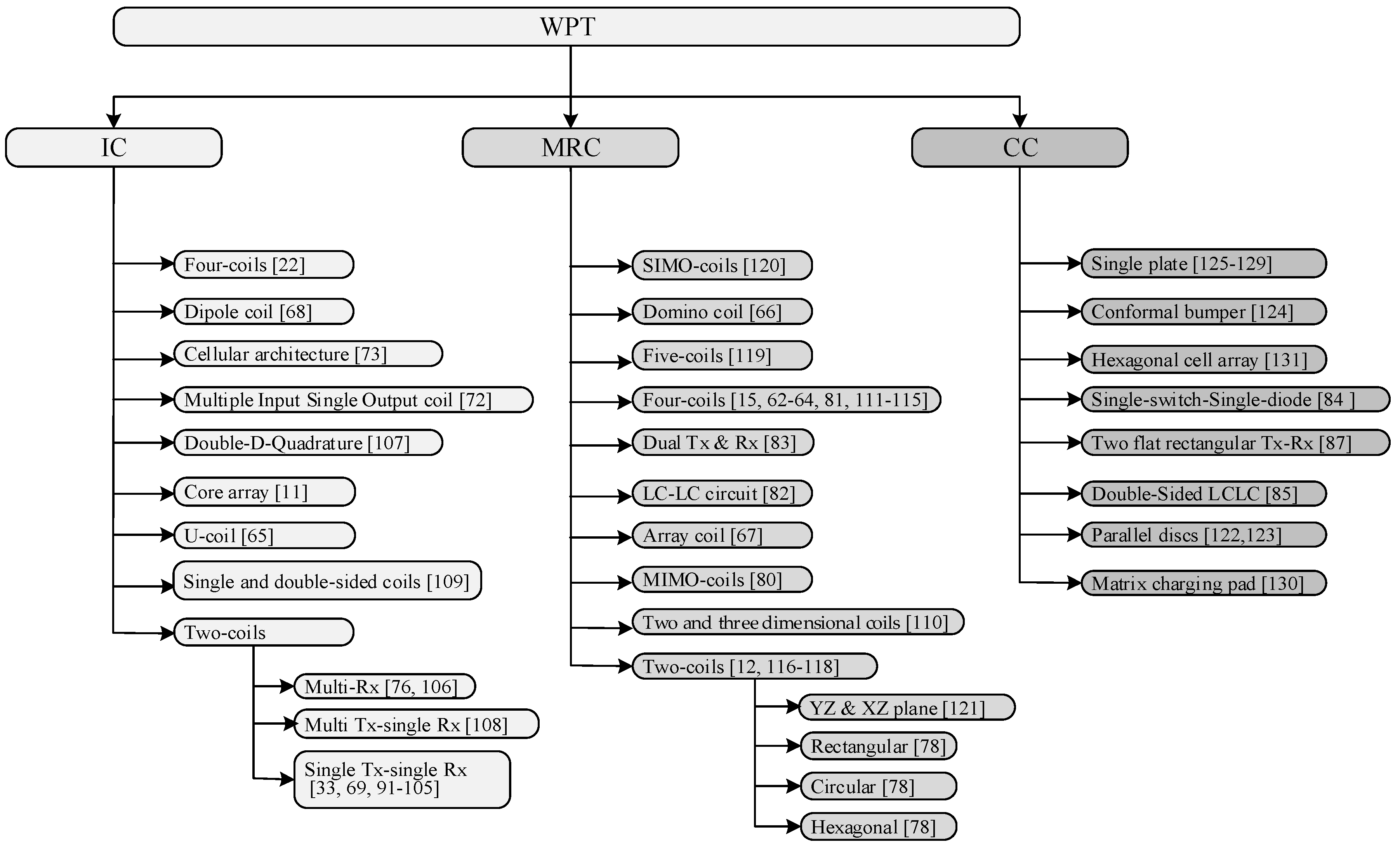
4. Classification of Near-Field Wireless Power Transfer Techniques

These technologies are classified based on the principal mechanism, power transfer, and transfer distance. Based on the power transfer air gap, WPT methods are divided into two categories: far field and near field. The technique can be considered far field if the wavelength of the electromagnetic signal is smaller than the transfer distance. By contrast, if the wavelength of the electromagnetic signal is longer than the transfer distance, the technique belongs to the near-field kind. For example, when the resonant frequency is relatively low (less than 5 MHz) and the transfer range is short (for example, 5 cm), the technique is near field. When the resonant frequency is 900 MHz and the range of power transfer is more than 2 m, the technique is characterized as far-field power transfer [48]. Microwaves, RF, photoelectric, laser, and acoustic can be classified as far-field energy transfer techniques, whereas inductive coupling and magnetic resonant coupling can be considered near-field techniques.
The transmission range of far-field techniques is up to several kilometers. Far-field techniques are subjected to trade-offs in the directionality of the antenna and transfer efficiency. Notably, transfer efficiency in the far-field technique remains low. The frequency band of the far-field method is extremely high, up to several GHz bands relative to near-field, thereby supporting the frequency range (kHz–MHz). Inductive coupling near-field techniques can be employed to transfer high power with significant efficiency in a very near distance up to several centimeters [49]. The efficiency of such techniques declines exponentially with the transfer distance. The magnetic resonant coupling can be employed in midrange applications with a suitable efficiency [17]. Figure 2 shows the subcategories of the near-field WPT techniques.

5. Performance Metrics Based on Wireless Power Transfer

In WPT, certain metrics such as frequency, transmitted power, efficiency, and transfer distance can be considered key parameters in determining the overall system performance. These key parameters are explained in detail in the following.

5.1. Frequency

The design of near-field WPT operating frequency has been implemented with regulatory constraints and a number of technical limitations [49]. For inductive coupling, the operating frequency varies in low frequency (LF) bands. For example, in [4], the authors adopted a frequency range of 20–40 kHz when the planned distance from coil to coil is roughly 10 cm. Magnetic resonant coupling systems typically work in high-frequency (HF) bands; a frequency range of 1–50 MHz was considered in [50]. In the magnetic resonant coupling method, high efficiency with a larger distance between the receiving and transmitting antennas can be achieved when their resonance frequencies are the same [51].
Experimental results of [52] show that frequency control can increase the transfer distances. For example, when the frequency band is 2 MHz, the transfer distance can only be roughly 50 cm, whereas the transfer distance can improve to 99.5 cm when the frequency band is adjusted to 30 MHz. Consequently, when the operating frequency increases to several GHz, the transfer efficiency can be improved and the receiving coil size can be minimized [53]. The far-field WPT technique is based on electromagnetic radiation; it operates in the microwave frequency band 2.4–5.8 GHz [54]. In this technique, the same frequency band can be utilized for WPT and communication information because the WPT uses the RF signals to obtain DC energy [55].

5.2. Energy Transfer

WPT can be categorized as radiative (i.e., far-field) and non-radiative (i.e., near-field). The radiative energy transfer technique can be classified into two types: directive and non-directive. For the non-directive application, omnidirectional radiation will be used to transfer energy to portable devices [4]. However, the omnidirectional characteristics of the radiated energy significantly reduce the system efficiency.
Non-radiative WPT mechanism originated from Tesla’s idea of a method that supplies power via wireless transmissions. Non-radiative WPT can be divided into two common types, namely, magnetic resonant coupling and inductive coupling for midrange and short-range power transfer applications, respectively [56]. The leakage inductance in the energy flow path can be reduced by using both magnetic resonant coupling and inductive coupling to enhance the energy transfer capability of the system [14]. When the maximum energy is consumed by the source, the transferred energy develops to a maximum value, which is subject to matching between source impedance and the input impedance of the source coil. Thus, the input impedance of the source coil is changed with the coupling coefficient alteration and working frequency of the source. The maximum energy transfer can occur at a specific coefficient value when working at a self-resonance frequency. This coefficient value is denoted as a crucial coupling point. The coupling coefficient matches the critical coupling at a specific distance. In mobile charging WPT, the coupling coefficient and transfer distance always vary, therefore, working at the coupling point is not appropriate [49].

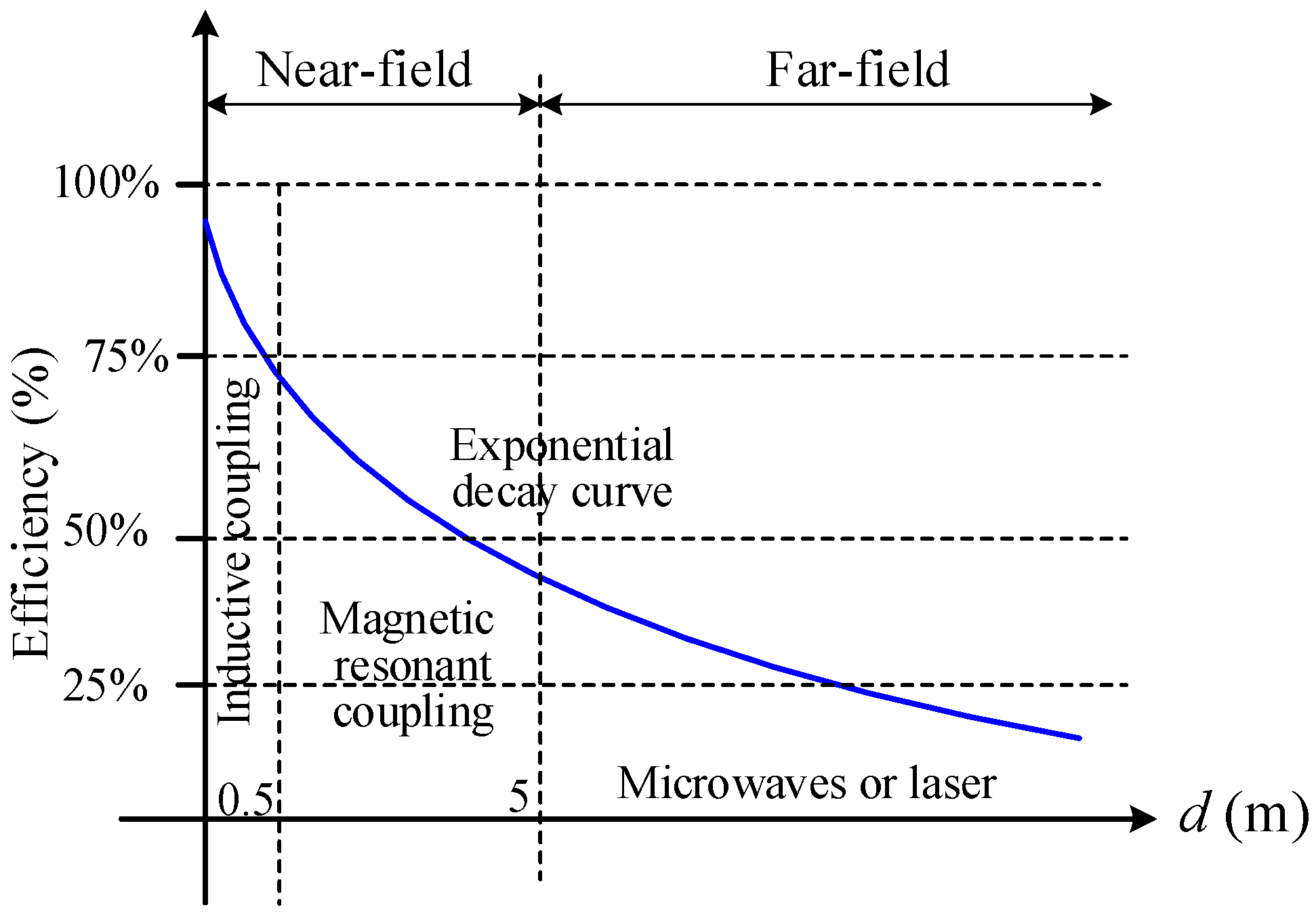
5.3. Efficiency of Power Transfer

Transfer efficiency is defined as the receiver power at the receiver coil divided by the total input at the transmitter coils. The efficiency of the WPT system depends on the type of technique. Figure 3 shows the transfer efficiency of the different WPT techniques for near and far fields. The inductive coupling technique achieves an energy transfer efficiency of 70–90%; it decreases with the distance between primary and secondary coils. To perform such a high efficiency, accurate alignment between primary and secondary coils is required [57]. Magnetic resonant coupling technique has a medium efficiency of 40–60% and also decays with distance. However, the transfer efficiency drops as it differs from the resonance frequency [58]. The efficiency of the microwave and laser is less than the previous two techniques by roughly 30%; furthermore, it decreases extremely quickly as the separation between the receiving and transmitting coils increases. The efficiency of the inductive and magnetic resonant coupling methods can be increased with a high-quality factor of the coils and depends on the coupling coefficient between resonators. In this case, a high operating frequency is required and the AC impedance of resonators must be low. However, operation with high frequency causes system complexity of electronic circuits [49]. The results of the work [59] disclosed that for any given coil, increasing the resonant frequency maximizes the power transfer; thus, the transfer efficiency will be improved.

5.4. Transfer Distance

The transfer distances or air gaps are considered a critical issue in near-field WPT because it determines the DC output power. The transfer distance varies from one type to another near-field WPT, where it depends on the uses of the power transfer technique. The inductive coupling technique has limited transfer distance with high transfer efficiency, whereas for magnetic resonant coupling, the energy can be transferred at midrange from source to load relative to the inductive coupling method. However, in this method, the transfer efficiency will be reduced. By contrast, the transfer distance becomes high with the electromagnetic wave method. However, the transfer efficiency is less than that of magnetic resonant coupling and inductive coupling techniques.
With the declaration of the Wireless Power Consortium (WPC) on extending the transfer distance from 5 mm to 40 mm in 2012, new research works are expected to focus on new magnetic winding schemes and configurations [56]. Based on the new developments in improving the transfer distance, a new planar design would be able to charge the devices on desks and tables. To address the poor transfer efficiency defects of a two-coil energy transfer mechanism, as considered in [20,23,59], midrange WPT techniques, such as relay resonators [60,61] (Figure 4a), four coils [15,62,63,64] (Figure 4b), U coils [65] (Figure 4c), domino coils [56,66] (Figure 4d), array coils [67] (Figure 4e), and dipole coils [68] (Figure 4f) are proposed in previous studies and fused into future planar WPT chargers with increased distances or air gaps. Based on these studies, the transfer distances were 20, 60, 100, 180 (for seven resonator coils), 20, and 500 cm ([60], [15], [65], [66], [67] and [68], respectively).
The four-coil WPT system comprises two resonant coupling coils and two main coils; one for source and the other for load. It is analyzed with basic circuit theory, as emphasized in [62], in which the transfer distance among the resonators coils can be maximized when matching occurs between the impedance of the source coil and impedance of the input of the four coils. Thus, the maximum energy transfer will be accomplished. Using matching impedance indicates that the system power transfer efficiency is restricted to 50% [56]. Kurs et al. [17] practically showed a transfer efficiency of 15% depending on the impedance matching process for four-coil WPT. A similar principle of impedance matching for the four-coil method can be applied to relay and domino resonator methods to maximize the energy transfer efficiency. Thus, the transfer efficiency will be maximized and the transfer distance will be improved. The pros and cons of the principle for middle-range near-field WPT (i.e., magnetic resonant coupling) applications, maximum energy transfer, and maximum transfer efficiency are discussed in [23].
However, when the number of resonator coils among the source and load coils increases, the transfer distance increases; thus, the transfer efficiency will be decreased. Therefore, a tradeoff between transfer distance and transfer efficiency is necessary. To lengthen the distance of WPT, the near-field magnetic resonant coupling can be a promising solution [13].
Table 2 summarizes the performance metrics for near-field WPT techniques. The table shows that the magnetic resonant coupling technique has more transfer distance of 5 m, and operates with high frequency up to tens of megahertz. However, this method has lower transfer efficiency relative to the other techniques (i.e., inductive and capacitive coupling).

6. Previous Works on Near-Field Wireless Power Transfer

Near-field WPT is a promising technology that can power up WSN objects, smartphones, and on-body medical implant devices without relying on the battery replacement or connecting into the main power supply. Several studies proposed different near-field WPT systems. The previous studies were reviewed for near-field WPT and are explained in detail in the following.

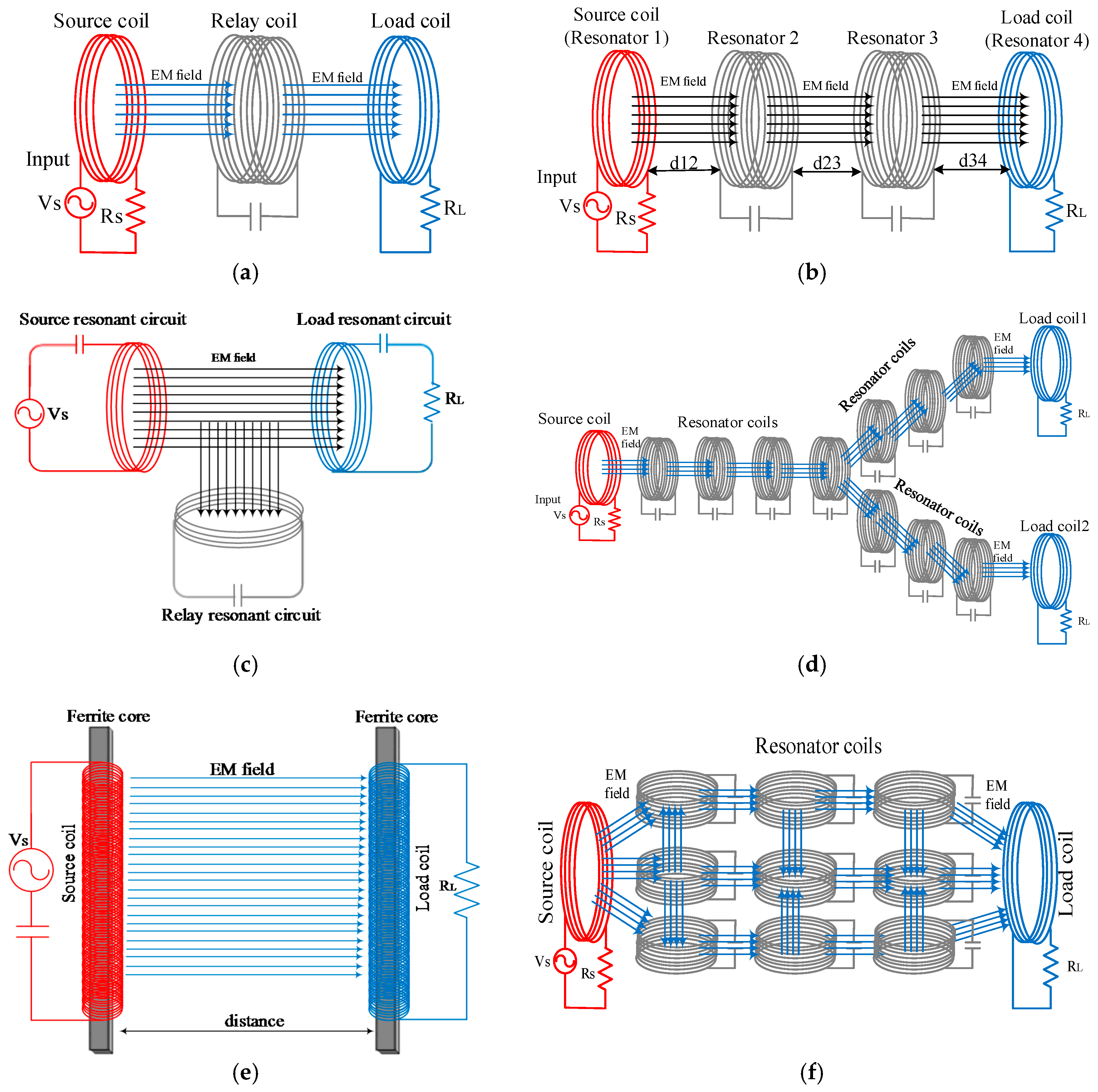
6.1. Inductive Coupling

In this section, some major studies related to inductive coupling WPT are highlighted and organized based on the chronology shown in Table 3. Some of these efforts are as follows:
Worgan et al. [69] presented a PowerShake to transfer power between mobile devices. PowerShake preserves high power transfer by approximately 3.1 W, which is adequate to charge power-hungry devices such as mobile phones. As stipulated by the authors, the output power of 3.1 W and generated frequency of 97 KHz of the transmitter keeps the tissue of the human body safe from electromagnetic field effects [70]. The design of their transmission and receiving circuits were subjected to Qi standards or specifications [71].
Another study [20] presented an inductive coupling WPT method to charge a mobile phone over a short distance; the researchers designed a power pad that involves an array of overlapping planar coils as a transmitter. The mobile device comprises a single planar coil as load or receiver that can receive power up to 1.2 W. This study determined that the transfer efficiency of the inductive coupling method decreases quickly when the air gap between the transmitter and receiver coils is changed, or axial misalignment occurs among the coils. The WPT system must consider these effects to preserve optimal efficiency.
Ye et al. [65] designed a new approach of inductive coupling that can transfer energy with a relatively greater distance than the traditional method. They proposed a new U-coil system method that consists of three coils, namely, a primary coil, a secondary coil, and a relay coil placed between the primary and secondary coils and that passes the energy between them. The researchers describe this method (i.e., U-coil WPT) to further improve energy efficiency than the two-coil method. This method achieves 100 cm of energy transfer between transmitter and receiver coils with working frequency of 85 kHz. Compared with the two-coil method, the power transfer efficiency of the U-coil method improved to 66%.
An efficient inductive power solution to increase the exchanging power distance between the receiver and the transmitter coils from 18 mm to 50 mm was presented in [72], where the multiple input single output (MISO) technique is adopted. Based on this technique, the magnetic flux leakage can be reduced by increasing the coil-to-coil distance. The results showed that the transmitted power improves more than 1.5 times (i.e., from 0.026 W to 0.042 W) at 5 cm distance between the receiving and transmitting coils. Consequently, the transfer efficiency also improves from 18% to 30%.
Zhong et al. [11] presented a novel WPT by adopting several coils at the primary side and one coil at the secondary side. The transmitter plate consists of several coils, with each coil wrapped around the ferrite core, whereas the receiver winding is fixed on the ferrite plate. Based on this configuration, several devices can be charged simultaneously with a transfer distance of 1.5 mm when they are placed in a free position at the charging plate. The researchers concluded that the optimal operating frequency range was 125–150 kHz, which could achieve 85% efficiency in the worst and best positions on the charging plate.
Multidimensional inductive WPT that uses a cellular approach was adopted by Agbinya and Mohamed [73]. The authors proposed one transmitting coil and six receiving coils. The coil structure is arranged in a hexagonal cell to transfer the energy over an air gap of 6 m and at least 1 V and 2% transfer efficiency can be obtained in the receiving coils. A couple of Helmholtz coils is used to provide uniform and strong energy transfer along the link axis. The results show that a full (100%) transfer efficiency can be achieved at a transfer distance of 5 cm, and the efficiency decreases quickly as the transfer distance increases between the receiving and transmitting coils. However, the transfer efficiency becomes 33% and 2% when the separation between coils increases to 1 m and 6 m, respectively.
Park et al. [68] improved the transfer distance to 5 m between primary and secondary coils using magnetic dipole-type coils with ferrite cores based on the inductive coupling idea. Their experimental results show that the transfer efficiencies are 29%, 16%, and 8% for transfer distances 3, 4, and 5 m at 20 kHz, respectively.
Inductive coupling WPT was adopted by the Hitachi Maxell and Murata companies [74] to wirelessly charge an iPad 2. Through this technology, 10 W power can be transferred from the pad charger to the iPad device within three hours for full charge. This method offers advantages, such as wireless charging, and the alignment between the pad and iPad 2 is not necessary, in which the iPad 2 can be charged in vertical or horizontal positions, and the pad can charge more than one iPad device. Rotating axis WPT is adopted by Sofia et al. [75] to supply power to the laboratory centrifuge machine. Transmitting and receiving coils are fixed on the same geometrical axis. The transmitting coil is constant whereas the receiving coil rotates with a rotor. The transmitting coil is excited at the oscillating frequency of 125 KHz and the power is transmitted to the receiving coil. The power is transferred between the two coils with 5 mm distance between. The power supply of the primary coil is 24 DC volts and the entire system aims to provide at least 10 W at the secondary coil in the rotary part to achieve 58% transfer efficiency.
Recently, Mai et al. [76] proposed a maximum power-point tracking control system to enhance system efficiency against the changes of the mutual inductances between the receivers and transmitter coils as well as the inductive load of the locomotives. A 2000 W proposed prototype is implemented to confirm the system performance. The total system DC to DC efficiency of 90.6% is obtained at rated power and is developed by 5.8% based on the suggested scheme under light load relative to the conventional fixed output voltage control scheme.
All modern consumer devices, from laptops to smartphones, still depend on plugs and cords for charging. These devices become unusable when their batteries die. Despite the various applications of electronic devices, the elimination or minimization of the use of power cable is the main focus of previous studies. Although power cables were the best solution for power transfer through cables, their ingrained drawbacks and the benefit of WPT techniques make the use of these technologies in electrical appliances and devices different. For this reason, electrical devices can be powered incessantly using the WPT system. Theoretically, wireless charging pad can be integrated into bedside and coffee tables, office environments, kitchens, and bathroom desktops to supply a wide range of consumer devices for low-power devices, such as shavers, tablets, and mobile phones, to high-powered devices, like inductive cooking utensils and kettles. Consequently, more WPT and related products are projected to come into the end user markets in the future. Inductive coupling WPT has several advantages and disadvantages:
Advantages: (i) short transfer distance; (ii) non-radiative, and therefore safe for human body; (iii) simple topology; (iv) high transfer efficiency of up to 95% at short distances; and (v) simple implementation.
Disadvantages: (i) short transfer distance (i.e., transfers energy with several centimeters); (ii) requires precise alignment in the charging orientation; (iii) produces eddy current over metal, (iv) heating effect; (v) inappropriate for mobile use; and (vi) needs fitted alignment between charging devices and WPT system.

6.2. Magnetic Resonant Coupling

Mittleider et al. [22] presented a novel method for charging wireless sensor networks based on UAVs. The UAV can be accurately localized to 15 cm based on magnetic resonant sensors, where the global positioning system (GPS) is inaccurate and needs line-of-sight between receiver and satellite [31]. However, the charging efficiency can be increased when the transmitting coil (mounted by UAV) and receiving coil (fixed in sensor node) are close to each other. Consequently, the charging power of 5.49 W at 6 cm distance between the receiving and transmitting coils are adequate to charge the battery of wireless sensor nodes at a remote location.
In reference [15], a variable coupling method to accomplish high efficiency in a resonance coupled WPT system was proposed. The WPT system comprises four identical coils. Two coils are found on each side of the transmitter (source) and receiver (load). In addition, both resonators were sensibly adjusted to reach the identical resonant frequencies. Therefore, a 6.7 MHz self-resonant frequency is generated in all coils. By applying the matching condition, the efficiency of WPT is improved. The matching condition is achieved by changing the coupling factors among the internal resonator and load. By applying the matching techniques experimentally, the energy transfer efficiencies are developed to 46.2% and 29.3% at a distances of 60 and 100 cm, respectively. However, the maximum efficiency was computed at 15 cm and was found to be 92.5%. Experimental outcomes revealed that the energy transfer efficiency increases dramatically by modifying its coupling factors across distance variations.
Cannon et al. [77] presented a lumped capacitor circuit for the WPT technique. The source or transmitter operates at a resonant frequency of 8.3 MHz. The conveyed power at the receiver coil is 28.2 mW; this value corresponds to 1.68 Volts at the transmitter coil. The results disclosed that when the receiver coil is placed 17 cm apart from the transmitter coil, the voltage drops from 3 V to 0.57 V, thereby corresponding to 3.3 mW energy conveyed at the receiver coil. Based on a large transmitter and either one or two small receiver coils, WPT via magnetic resonant coupling is implemented. A circuit design is established to identify the scheme with one receiver coil and expanded to identify the method with two receiver coils.
Chen et al. [78] designed three cost-effective couplers (i.e., circular, rectangular, and hexagonal) for WPT dedicated to electric vehicle dynamic charging. The output power, tolerance of horizontal offset, transfer efficiency, and flux density are discussed. In their work, the proposed charging method is analyzed and compared by both experimental and simulation methods. The operating frequency of the proposed system was 35 kHz, and the length of the air gap is 200 mm between the primary and secondary coils for all three types. The authors concluded that the transfer efficiency decreases with the load resistance, and the mutual inductance among coils controls the quantity of transfer energy from the primary coil to the secondary coil. Chen et al. [79] presented an improved theory of the WPT system. A magnetic resonant coupling tuning scheme is suggested to transfer a scheduled amount of energy via lossy coils at high efficiency. The tuning approach can increase the transfer distance, but the research is limited to simulation results.
Jadidian and Katabi [80] showed a mobile phone being charged remotely and working independently even though the phone is in the user’s pocket, thereby benefiting from the idea of multiple-input multiple-output (MIMO) beamforming. Unlike beamforming in the wireless communication system, a non-radiated magnetic field is developed and directed toward the mobile phone and portable devices. The proposed MIMO system runs at a single frequency of 1 MHz and can charge a mobile phone at distances of roughly 0.5–40 cm with power transfer efficiency equal to 89%.
Sun et al. [81] suggested a new WPT scheme that is directly strong coupling, which considers only two resonator circuits and accomplishes strong-coupling renderings. Two heterogeneous helical antennas were used: one for the transmitter and the other for the receiver to minimize the size for indoor usage. Unlike the strong coupling technique with four helical antennas (i.e., two low-Q helical antennas and two high-Q helical antennas), their proposed approach considers only two helical antennas (two high-Q helical antennas) to perform strong-coupling renderings. The two antennas were designed to operate at the same resonant frequency of 8.4 MHz. Experimental results demonstrate that the power that can be transferred between receiver and transmitter coils is 50 cm and 100 cm, with a transfer efficiency of 40.3% and 35.6%, respectively.
Wang et al. [82] proposed q-Z source and H-bridge to adjust the charging current of an electrical vehicle. Therefore, the power transfer will be improved. A prototype is developed, which can convey 3000 W from transmitter coil to receiver coil over a transfer air gap of 20 cm with maximum efficiency of 95%.
Recently, Yong et al. [83] proposed a dual receiver and dual transmitter-based WPT configuration by employing power rating semiconductors and lower cost. The availability and reliability of the proposed system are improved based on the suggested structure of four transfer paths. The output power of 2100 W with a system efficiency of 93.62% was obtained at 70 mm separation distance between the primary and secondary coils. Magnetic resonator coupling WPT has several advantages and disadvantages, summarized in the following:
Advantages: (i) transfer energy within several meters; (ii) line-of-sight (LOS) is not required when devices are charged; (iii) unaffected by weather environments; (iv) high transfer efficiency under omnidirectional antenna; (v) alignment between the transmitted and receiving coils is not necessary; (vi) charging several devices concurrently on dissimilar power; and (vii) appropriate for mobile applications.
Disadvantages: (i) low-transfer power for consumer devices; (ii) decreased efficiency because of axial mismatch between receiver and transmitter coils; (iii) decreased efficiency with increased distance; and (iv) complex implementation.

6.3. Capacitive Coupling

In this section, several major efforts associated with capacitive coupling WPT are discussed, and these works are organized based on the chronology shown in Table 3. Compared to inductive coupling, capacitive coupling is still an emerging technique that has been discussed by fewer scholars [24]. However, capacitive coupling can be utilized in similar low-power applications to the inductive coupling, like charging of mobile and biomedical devices. Some of these applications can be deliberated in some efforts as detailed in the following. Capacitive coupling is commonly used in low-power applications because it has a small coupling capacitance.
In [84], the authors suggested high power-transfer levels while maintaining cost effectiveness by using capacitive coupling WPT. The authors proposed and studied four active capacitive coupling topologies, which rely on canonical Ćuk, Zeta, “single-ended primary-inductor converter (SEPIC)”, and buck-boost converters. The experimental results disclosed that the transfer power at 200 kHz is developed to 1 kW with a transfer efficiency of 90%.
Compensated capacitive coupling based on a double-sided LC-LC network is proposed by Lu and Zhang [85] to charge electrical vehicles. Two couples of metal plates are developed to become a part of a two-coupling capacitor system to transfer energy wirelessly. Four 610 × 610 mm2 copper plates with separation of 15 and 30 cm between two plates are designed. A 2.4 and 1.6 kW with a transfer efficiency of 90.8% and 89.1% are obtained for air gap distances of 15 and 30 cm, respectively. The authors concluded that their system is robust in case of distance variations and misalignment.
A novel technique, known as capacitive coupling coefficient is presented by Huang and Hu [86] to evaluate the coupling condition between the plates of the coupling capacitor. Based on electric charge evenness, the capacitive coupling coefficient is modeled by deriving a mathematical model for capacitive coupling plates. The physical meaning with regard to mutual capacitance and equivalent primary/secondary plates is clarified by comparing two capacitive coupling systems with diverse cross-coupling arrangements.
A capacitive coupling system that uses a class-E amplifier is proposed by Yusop et al. [87]. A class-E amplifier is selected due to its ability to achieve DC-to-AC conversion efficiently while considerably minimizing switching losses, consuming low power, providing a stable output voltage, and having the characteristic of simplicity [88]. The proposed capacitive coupling is formed by two conductive rectangular plates; one acts as a transmitter and the other as a receiver. The effect of several coupling distances on output power is investigated. Laboratory experiments are conducted to verify the proposed system, which works at a coupling gap of 0.25 mm and operating frequency of 1 MHz. Based on various coupling distances in the range of 0.25–2 mm, the power transfer efficiency within the range of 96.3–91% can be accomplished.
In [89], a conjugate image scheme is applied for capacitive coupling WPT to determine the ideal compensation of input and output ports of the network to transfer power at maximum efficiency. In addition, parallel and serial topologies are implemented to improve the energy transfer efficiency. The results of the capacitive coupling are compared relative to the inductive coupling in terms of coupling function and conjugate image scheme. Therefore, a well comprehension of the basics of the WPT link can be obtained to develop a more efficient system.
The comparison of the performance metrics for the previous studies can be summarized in Table 3, arranged based on the categories listed in Figure 2, and sorted based on the percentage of efficiency (from high to low). The review of the aforementioned studies shows that the designed charger platforms are limited to a short distance of a few centimeters and high transfer efficiency for the near-field WPT, and these platforms need a device that is intended to charge when completely aligned with the charging pad.
Ultracapacitors have been innovated by the Maxwell company [90] to supply energy to the bus (hybrid-electric buses), rail (trams and trains), trucks, forklifts, and cranes. Approximately 2000 medium- and heavy-duty trucks on the street in North America use the Maxwell ultracapacitor-based engine start module. The ultracapacitors of Maxwell achieved extremely fast and efficient storage and discharged power.
“Maxwell’s ultracapacitor” solutions that are used to power medium and heavy mining equipment and earth-moving are best for flexible power storage solutions because an ultracapacitor is cost-effective and it outperforms other options in reliability, durability, and productivity factors. The life and autonomy of equipment can be increased to more than 25% relative to traditional equipment, especially for hoisting and lifting applications. Thus, the cost of maintenance and downtime will be increased. For example, the braking energy of a rail can be stored in ultracapacitor modules to provide bridged power, assisted propulsion, and grid voltage in several rail applications today. In addition, ultracapacitors are used to deliver power to a starting locomotive engine. Ultracapacitors are also used to exclude large batteries or to prolong the lifetime of a battery. Ultracapacitors are currently widely applied because of their advantages, including: (i) fast recharge rate; (ii) high amount of burst energy delivery; (iii) long service life; (iv) broad working temperature range; (vi) safe technology; and (vii) acid- and lead-free features. Ultracapacitors can be used in a wide domain of future applications because of these benefits.
Recently, a new single-person electrical vehicle was invented by the Toyohashi University of Technology [132]. The Toyohashi prototype EV acquires energy wirelessly from a pair of metal electrodes placed under the car track through steel straps that are installed inside the front tires. The energy is transferred between metal electrodes and steel straps using the displacement current, which is converted into direct current through bridge rectifiers. In this invention, a 5000 W power at operating frequency of 13.56 MHz can be supplied to the electrical vehicle. The single-person electrical vehicle can be supplied with power instead of 120 kg lead–acid battery to become a battery-free electrical vehicle. The Toyohashi team expects to develop the performance of the vehicle in terms of transfer efficiency, driving performance, and safety in the future.
Capacitive coupling WPT has several advantages and disadvantages:
Advantages: (i) power is transferred via metal; (ii) high transfer efficiency; (iii) high output power for EV applications; and (iv) simple design.
Disadvantages: (i) large coupling area is needed when high power is required and (ii) small transfer distance.

7. Challenges and Limitations of Near-Field Wireless Power Transfer

The following subsections discuss the challenges in near-field WPT studies in terms of: (i) health and security; (ii) metallic components; and (iii) transfer distance and efficiency.

7.1. Health and Security Challenges for Wireless Power Transfer

Security and safety concerns exist in WPT and their possible countermeasures, such as beamforming, jamming, monitoring, safety, charging, spoofing, and software [133]. In this subsection, the security and health issues are discussed. Many solutions in terms of safety and security were presented by Liu et al. [133]. WPT-based RF had already become a promising solution to power a wide range of low-power embedded devices wirelessly. However, safety and security aspects are overlooked by the community. The motivation to address the safety and security problems related to WPT emphasizes their importance in terms of efficient and dependable operation of RF-based WPT. Liu et al. [133] provided an overview of new research opportunities in this emerging domain and shown that WPT is weak to attacks. Barman et al. [14] explained the human exposure to electromagnetic fields following safety considerations. They reviewed some of the previous studies related to human exposure, safe human exposure limits for resonant-coupled WPT, and EM exposure analysis by using the human body paradigm.
The WPT could pose challenges in clinical uses when working at high frequencies. To obtain high power transfer and a smaller reception coil size, the working frequency of the RF WPT must be increased to the GHz band [134,135,136]. Within this band, a precise impedance matching is required in both the receiving and transmitting circuits to perform the preferred transfer power delivery efficiency [137]. In addition, the impedance matching condition of both the receiving and transmitting coils are invisible in several medical applications because they are critical to the air gap and alignment between the receiving and transmitting coils [53], as well as the electrical characteristics of the bio-tissues among the coils [138]. Careful configuration between the coils and precise understanding of the electrical properties of the propagation channel might be a challenge in medical applications. Moreover, conductive bio-tissues could considerably decrease the delivered transfer power in the RF band because of absorption [53]. Following the IEEE Standard C95.1-2005 [70], for safety levels with regard to human body exposure to RF electromagnetic waves, the allowable exposure level in the range of 2 to 100 GHz in public surroundings is 10W/m2 [70].

7.2. Metallic Components Challenge for Wireless Power Transfer

Version 1.1 of the “Qi” standard, which is an open interface standard developed by the WPC, enabled the mobile electronic devices to be charged wirelessly with limited transfer power up to 5 W [56]. Thus, Qi is an appropriate technique to cover planar wireless charging for an extensive range of low power devices such as iPods, Bluetooth earpieces, mobile phones, and so on. Future criteria are expected to prolong transfer power capability to 120 W; thus, more mobile devices, such as notebook computers and iPads, can be covered. Given the growing quantity of wireless power transfer, many practical challenges will appear, specifically in the electromagnetic field, electromagnetic compatibility, and thermal aspects. Given that the batteries of the devices are frequently inserted into these electronic devices with no or limited air circulation, extremely energy-efficient power transformation mechanisms are necessary to reduce the power consumption or losses in the receiver components. Consequently, the temperature increases in the battery sets. The interactions between the transmission and reception information and AC charging flux of the electronic circuit loads require special consideration. The high charging flux density means that the AC flux can induce eddy currents in any unintended metallic components inside the electronic circuit loads. Induced current leads to internal temperature increases and circuit damage.
The requirements for slim designs in several modern electronic devices might conflict with the dimensions of the electromagnetic shields. In addition to the power losses in the secondary and primary circuits, coils, and magnetics, strange entities such as ferromagnetic or metallic ones in the vicinity of the flux routes can also absorb the radiated power. If these materials are placed in the middle of the AC magnetic flux, induced eddy currents will be produced and circulated within the materials, thereby resulting in temperature rise and conduction losses. If the conduction loss is considerable, the subsequent temperature growth in the materials could be a safety concern and a probable factor that leads to system damage or failure [139]. For example, the power wastage of 0.5–1 W in metallic materials such as gold rings, paper clips, coins, and metalized pharmaceutical wrapping can increase the entity temperature above 80 °C [56].

7.3. Transfer Distance and Efficiency Challenges for Wireless Power Transfer

The creation of WPT dates back to the 19th century, when Tesla invented the Tesla coil. Several studies have been directed in this area in recent years, but transfer distance and transfer efficiency of WPT methods continue to pose a challenge. Although experiments were conducted by many researchers and extensive efforts for near-field WPT (i.e., inductive coupling and magnetic resonant coupling techniques) were presented, a number of practical challenges can be identified, such as orientation and interference. The first challenge is the alignment or orientation between the source and destination coils. The maximum transfer distance can be achieved if and only if the coaxial alignment is ensured between the coils. Other orientation settings, such as 45° rotation or coplanar relative to the coaxial alignment, minimize the coupling factor between the receiving and transmitting coils; therefore, the transfer distance and efficiency are reduced. Second, when these technologies are expanded to charge several devices, mutual coupling between different receiving coils and other entities may cause interference; then, watchful tuning is required [12].

8. Conclusions and Potential Opportunities in Near-Field Wireless Power Transfer

This study provided a review of near-field WPT techniques that are available academically. An evaluation of the previous studies for near-field WPT was introduced. The paper presented a concise review of recent WPT advancements that are specific to near-field techniques. Classification of near-field WPT techniques was presented and the performance metrics for these techniques were compared. Applications of these techniques were also emphasized. Previous studies on magnetic resonant coupling are promising. Magnetic resonant coupling WPT requires further studies to enhance the design of the resonators to perform high-transfer distance and maximum power transfer during angular or axial misalignment, to reduce system losses when high-oscillation frequency is used, and to increase the dynamic frequency and power control schemes to reduce the effect of EM waves on the human body to meet international standards.
Inductive coupling can be used for planar applications with high efficiency and short air gaps, such as mobile phone pads. Inductive coupling can be used for mid-range applications, e.g., charging the WSN or UAV, with suitable transfer distance and transfer efficiencies.
UAVs can be employed to charge the batteries of WSNs deployed in a vast area. However, the flight time of the UAV is restricted because of the limited battery capacity. In this case, the use of inductive coupling WPT technique is suggested to charge the UAV battery, which in turn charges the sensor nodes using the same technique or magnetic resonant coupling WPT. The UAV thus extends the communication range of WSNs without human intervention. In addition, the flight distance of the UAV between source and destination is approximately doubled relative to traditional flight (i.e., without the WPT technique). Charging the UAV through another UAV or mobile node is another research trend. Also, recent development in magnetic resonant coupling WPT reveals that several nodes can be charged simultaneously. This integration between UAV and WSN in outdoor surroundings will introduce different trends for research and enable a new design to solve charging problems.
Conventional transport vehicles are expected to be replaced by electrical vehicles in the near future in spite of commercial and technical obstacles. The extended mileage is the main challenge for future electrical vehicles. At long distances, electrical vehicles require high-battery power that may be charged within a few minutes.

Acknowledgments

Authors would like to thanks Al-Rafidain University College for their generosity in financial assistance.

Author Contributions

Aqeel Mahmood Jawad, Rosdiadee Nordin, and Sadik Kamel Gharghan classified the WPT techniques as well as they surveyed and compared early research works on WPT; Haider Mahmood Jawad and Sadik Kamel Gharghan explored the challenges and limitations of WPT; Aqeel Mahmood Jawad and Haider Mahmood Jawad examined the performance metrics for previous research works in near-field WPT. All authors wrote the paper.

Conflicts of Interest

The authors declare no conflict of interest.

References

  1. Tomar, A.; Gupta, S. Wireless power transmission: Applications and components. Int. J. Eng. 2012, 1, 1–8. [Google Scholar]
  2. Shinohara, N. History, Present and Future of WPT, in Wireless Power Transfer Via Radiowaves; John Wiley & Sons, Inc.: Hoboken, NJ, USA, 2013. [Google Scholar]
  3. Cichon, D.J.; Wiesbeck, W. The Heinrich Hertz wireless experiments at Karlsruhe in the view of modern communication. In Proceedings of the 1995 International Conference on 100 Years of Radio, London, UK, 5–7 September 1995; pp. 1–6. [Google Scholar]
  4. Shadid, R.; Noghanian, S.; Nejadpak, A. A literature survey of wireless power transfer. In Proceedings of the IEEE International Conference on Electro Information Technology (EIT), Grand Forks, ND, USA, 19–21 May 2016; pp. 782–787. [Google Scholar]
  5. Brown, W.C. The history of power transmission by radio waves. IEEE Trans. Microw. Theory Technol. 1984, 32, 1230–1242. [Google Scholar] [CrossRef]
  6. Kesler, M. Highly Resonant Wireless Power Transfer: Safe, Efficient, and over Distance; Witricity Corp.: Watertown, MA, USA, 2013; pp. 1–32. [Google Scholar]
  7. Miller, J.M.; Jones, P.T.; Li, J.-M.; Onar, O.C. ORNL experience and challenges facing dynamic wireless power charging of EV’s. IEEE Circuits Syst. Mag. 2015, 15, 40–53. [Google Scholar] [CrossRef]
  8. Olivares-Galvan, J.C.; Campero-Littlewood, E.; Magdaleno-Adame, S.; Maximov, S.; Xu, W. Wireless power transfer: Literature survey. In Proceedings of the 2013 IEEE International Autumn Meeting on Power, Electronics and Computing (ROPEC), Mexico City, Mexico, 13–15 November 2013; pp. 1–7. [Google Scholar]
  9. Chen, X.; Ng, D.W.K.; Chen, H.-H. Secrecy wireless information and power transfer: Challenges and opportunities. IEEE Wirel. Commun. 2016, 23, 54–61. [Google Scholar] [CrossRef]
  10. Simic, M.; Bil, C.; Vojisavljevic, V. Investigation in wireless power transmission for UAV charging. Procedia Comput. Sci. 2015, 60, 1846–1855. [Google Scholar] [CrossRef]
  11. Zhong, W.; Liu, X.; Hui, S.R. A novel single-layer winding array and receiver coil structure for contactless battery charging systems with free-positioning and localized charging features. IEEE Trans. Ind. Electron. 2011, 58, 4136–4144. [Google Scholar] [CrossRef] [Green Version]
  12. Xie, L.; Shi, Y.; Hou, Y.T.; Lou, A. Wireless power transfer and applications to sensor networks. IEEE Wirel. Commun. 2013, 20, 140–145. [Google Scholar]
  13. Xia, M.; Al, S. On the efficiency of far-field wireless power transfer. IEEE Trans. Signal Process. 2015, 63, 2835–2847. [Google Scholar] [CrossRef]
  14. Barman, S.D.; Reza, A.W.; Kumar, N.; Karim, M.E.; Munir, A.B. Wireless powering by magnetic resonant coupling: Recent trends in wireless power transfer system and its applications. Renew. Sustain. Energy Rev. 2015, 51, 1525–1552. [Google Scholar] [CrossRef]
  15. Duong, T.P.; Lee, J.W. Experimental results of high-efficiency resonant coupling wireless power transfer using a variable coupling method. IEEE Microw. Wirel. Compon. Lett. 2011, 21, 442–444. [Google Scholar] [CrossRef]
  16. Hsu, H.M.; Chien, C.T.; Wu, D.Y. Transceiver chip design in high voltage 0.25µm cmos technology for magnetic resonance system. In Proceedings of the IEEE Wireless Power Transfer Conference (WPTC), Boulder, CO, USA, 13–15 May 2015; pp. 1–3. [Google Scholar]
  17. Kurs, A.; Karalis, A.; Moffatt, R.; Joannopoulos, J.D.; Fisher, P.; Soljačić, M. Wireless power transfer via strongly coupled magnetic resonances. Science 2007, 317, 83–86. [Google Scholar] [CrossRef] [PubMed]
  18. Kim, Y.-H.; Kang, S.Y.; Cheon, S.; Lee, M.L.; Zyung, T. Optimization of wireless power transmission through resonant coupling. In Proceedings of the SPEEDAM 2010, Badajoz, Spain, 20–22 May 2019; pp. 1069–1073. [Google Scholar]
  19. Mohammadian, A.H.; Ozaki, E.T.; Grob, M.S. Repeaters for Enhancement of Wireless Power Transfer. U.S. Patent 8,611,815 B2, 6 November 2008. [Google Scholar]
  20. Waffenschmidt, E.; Staring, T. Limitation of inductive power transfer for consumer applications. In Proceedings of the 13th European Conference on Power Electronics and Applications EPE’09, Barcelona, Spain, 8–10 September 2009; pp. 1–10. [Google Scholar]
  21. Hwang, K.; Cho, J.; Kim, D.; Park, J.; Kwon, J.H.; Kwak, S.I.; Park, H.H.; Ahn, S. An autonomous coil alignment system for the dynamic wireless charging of electric vehicles to minimize lateral misalignment. Energies 2017, 10, 315. [Google Scholar] [CrossRef]
  22. Mittleider, A.; Griffin, B.; Detweiler, C. Experimental analysis of a uav-based wireless power transfer localization system. In Experimental Robotics: The 14th International Symposium on Experimental Robotics; Hsieh, M.A., Khatib, O., Kumar, V., Eds.; Springer: Cham, Switzerland, 2016; pp. 357–371. [Google Scholar]
  23. Hui, S.Y.R.; Zhong, W.; Lee, C.K. A critical review of recent progress in mid-range wireless power transfer. IEEE Trans. Power Electron. 2014, 29, 4500–4511. [Google Scholar] [CrossRef]
  24. Dai, J.; Ludois, D.C. A survey of wireless power transfer and a critical comparison of inductive and capacitive coupling for small gap applications. IEEE Trans. Power Electron. 2015, 30, 6017–6029. [Google Scholar] [CrossRef]
  25. Yilmaz, M.; Krein, P.T. Review of battery charger topologies, charging power levels, and infrastructure for plug-in electric and hybrid vehicles. IEEE Trans. Power Electron. 2013, 28, 2151–2169. [Google Scholar] [CrossRef]
  26. Kalwar, K.A.; Aamir, M.; Mekhilef, S. Inductively coupled power transfer (ICPT) for electric vehicle charging—A review. Renew. Sustain. Energy Rev. 2015, 47, 462–475. [Google Scholar] [CrossRef]
  27. Khaligh, A.; Dusmez, S. Comprehensive topological analysis of conductive and inductive charging solutions for plug-in electric vehicles. IEEE Trans. Veh. Technol. 2012, 61, 3475–3489. [Google Scholar] [CrossRef]
  28. Lukic, S.; Pantic, Z. Cutting the cord: Static and dynamic inductive wireless charging of electric vehicles. IEEE Electr. Mag. 2013, 1, 57–64. [Google Scholar] [CrossRef]
  29. Bi, Z.; Kan, T.; Mi, C.C.; Zhang, Y.; Zhao, Z.; Keoleian, G.A. A review of wireless power transfer for electric vehicles: Prospects to enhance sustainable mobility. Appl. Energy 2016, 179, 413–425. [Google Scholar] [CrossRef]
  30. Akhtar, F.; Rehmani, M.H. Energy replenishment using renewable and traditional energy resources for sustainable wireless sensor networks: A review. Renew. Sustain. Energy Rev. 2015, 45, 769–784. [Google Scholar] [CrossRef]
  31. Choi, S.Y.; Gu, B.W.; Jeong, S.Y.; Rim, C.T. Advances in wireless power transfer systems for roadway-powered electric vehicles. IEEE J. Emerg. Sel. Top. Power Electron. 2015, 3, 18–36. [Google Scholar] [CrossRef]
  32. Mou, X.; Sun, H. Wireless Power Transfer: Survey and Roadmap. In Proceedings of the IEEE 81st Vehicular Technology Conference (VTC Spring), Glasgow, UK, 11–14 May 2015; pp. 1–5. [Google Scholar]
  33. Esteban, B.; Sid-Ahmed, M.; Kar, N.C. A comparative study of power supply architectures in wireless ev charging systems. IEEE Trans. Power Electron. 2015, 30, 6408–6422. [Google Scholar] [CrossRef]
  34. Lu, Y.; Ma, D.B. Wireless power transfer system architectures for portable or implantable applications. Energies 2016, 9, 1087. [Google Scholar] [CrossRef]
  35. Oodachi, N.; Kudo, H.; Ogawa, K.; Shoki, H.; Obayashi, S.; Morooka, T. Efficiency improvement of wireless power transfer via magneticresonance using the third coil. ISAP 2010, 52. [Google Scholar] [CrossRef]
  36. Imura, T.; Uchida, T.; Hori, Y. Flexibility of contactless power transfer using magnetic resonance coupling to air gap and misalignment for ev. World Electr. Veh. J. 2009, 3, 24–34. [Google Scholar]
  37. Hanazawa, M.; Ohira, T. Power transfer for a running automobile. In Proceedings of the International Microwave Workshop Series on Innovative Wireless Power Transmission: Technologies, Systems, and Applications (IMWS), Kyoto, Japan, 12–13 May 2011; pp. 77–80. [Google Scholar]
  38. Kumagai, T.; Saito, K.; Takahashi, M.; Ito, K. Design of receiving antenna for microwave power transmission to capsular endoscope. In Proceedings of the International Microwave Workshop Series on Innovative Wireless Power Transmission: Technologies, Systems, and Applications (IMWS), Kyoto, Japan, 12–13 May 2011; pp. 145–148. [Google Scholar]
  39. Kim, S.; Ho, J.S.; Chen, L.Y.; Poon, A.S. Wireless power transfer to a cardiac implant. Appl. Phys. Lett. 2012, 101, 073701. [Google Scholar] [CrossRef]
  40. Griffin, B.; Detweiler, C. Resonant wireless power transfer to ground sensors from a UAV. In Proceedings of the IEEE International Conference on Robotics and Automation (ICRA), Minnesota, MI, USA, 14–18 May 2012; pp. 2660–2665. [Google Scholar]
  41. McDonough, M. Integration of inductively coupled power transfer and hybrid energy storage system: A multiport power electronics interface for battery-powered electric vehicles. IEEE Trans. Power Electron. 2015, 30, 6423–6433. [Google Scholar] [CrossRef]
  42. Brecher, A.; Arthur, D. Review and Evaluation of Wireless Power Transfer (WPT) for Electric Transit Applications; Volpe National Transportation Systems Center: Cambridge, MA, USA, 2014; pp. 1–61.
  43. Yang, Y.; Yeo, J.; Priya, S. Harvesting energy from the counterbalancing (weaving) movement in bicycle riding. Sensors 2012, 12, 10248–10258. [Google Scholar] [CrossRef] [PubMed]
  44. Chiu, H.-W.; Lin, M.-L.; Lin, C.-W.; Ho, I.-H.; Lin, W.-T.; Fang, P.-H.; Li, Y.-C.; Wen, Y.-R.; Lu, S.-S. Pain control on demand based on pulsed radio-frequency stimulation of the dorsal root ganglion using a batteryless implantable cmos soc. IEEE Trans. Biomed. Circuits Syst. 2010, 4, 350–359. [Google Scholar] [CrossRef] [PubMed]
  45. Ha, B.W.; Park, J.A.; Jin, H.J.; Cho, C.S. Energy transfer and harvesting for RF-Bio applications—Invited. In Proceedings of the International Microwave Workshop Series on RF and Wireless Technologies for Biomedical and Healthcare Applications (IMWS-BIO), Taipei, Taiwan, 21–23 September 2015; pp. 54–55. [Google Scholar]
  46. Sun, T.; Xie, X.; Li, G.; Gu, Y.; Deng, Y.; Wang, Z. A two-hop wireless power transfer system with an efficiency-enhanced power receiver for motion-free capsule endoscopy inspection. IEEE Trans. Biomed. Eng. 2012, 59, 3247–3254. [Google Scholar] [PubMed]
  47. Liu, L.; Zhang, R.; Chua, K.C. Secrecy wireless information and power transfer with miso beamforming. IEEE Trans. Signal Process. 2014, 62, 1850–1863. [Google Scholar] [CrossRef]
  48. Sun, T.; Xie, X.; Wang, Z. Wireless Power Transfer for Medical Microsystems; Springer: New York, NY, USA, 2013; p. 183. [Google Scholar]
  49. Vilathgamuwa, D.M.; Sampath, J.P.K. Wireless power transfer (WPT) for electric vehicles (EVS)—Present and future trends. In Plug in Electric Vehicles in Smart Grids: Integration Techniques; Rajakaruna, S., Shahnia, F., Ghosh, A., Eds.; Springer: Singapore, 2015; pp. 33–60. [Google Scholar]
  50. Christ, A.; Douglas, M.; Nadakuduti, J.; Kuster, N. Assessing human exposure to electromagnetic fields from wireless power transmission systems. Proc. IEEE 2013, 101, 1482–1493. [Google Scholar] [CrossRef]
  51. Imura, T.; Hori, Y. Maximizing air gap and efficiency of magnetic resonant coupling for wireless power transfer using equivalent circuit and neumann formula. IEEE Trans. Ind. Electron. 2011, 58, 4746–4752. [Google Scholar] [CrossRef]
  52. Tan, L.; Huang, X.; Huang, H.; Zou, Y.; Li, H. Transfer efficiency optimal control of magnetic resonance coupled system of wireless power transfer based on frequency control. Sci. China Technol. Sci. 2011, 54, 1428–1434. [Google Scholar] [CrossRef]
  53. Jiang, H.; Zhang, J.; Lan, D.; Chao, K.K.; Liou, S.; Shahnasser, H.; Fechter, R.; Hirose, S.; Harrison, M.; Roy, S. A low-frequency versatile wireless power transfer technology for biomedical implants. IEEE Trans. Biomed. Circuits Syst. 2013, 7, 526–535. [Google Scholar] [CrossRef] [PubMed]
  54. Jang, B.-J.; Lee, S.; Yoon, H. Hf-band wireless power transfer system: Concept, issues, and design. Prog. Electromagn. Res. 2012, 124, 211–231. [Google Scholar] [CrossRef]
  55. Yoshida, S.; Noji, T.; Fukuda, G.; Kobayashi, Y.; Kawasaki, S. Experimental demonstration of coexistence of microwave wireless communication and power transfer technologies for battery-free sensor network systems. Int. J. Antennas Propag. 2013, 2013, 357418. [Google Scholar] [CrossRef]
  56. Hui, S. Planar wireless charging technology for portable electronic products and qi. Proc. IEEE 2013, 101, 1290–1301. [Google Scholar] [CrossRef] [Green Version]
  57. Shoki, H. Issues and initiatives for practical deployment of wireless power transfer technologies in Japan. Proc. IEEE 2013, 101, 1312–1320. [Google Scholar] [CrossRef]
  58. Huang, K.; Lau, V.K. Enabling wireless power transfer in cellular networks: Architecture, modeling and deployment. IEEE Trans. Wirel. Commun. 2014, 13, 902–912. [Google Scholar] [CrossRef] [Green Version]
  59. Mur-Miranda, J.O.; Fanti, G.; Feng, Y.; Omanakuttan, K.; Ongie, R.; Setjoadi, A.; Sharpe, N. Wireless power transfer using weakly coupled magnetostatic resonators. In Proceedings of the IEEE Energy Conversion Congress and Exposition, Atlanta, GA, USA, 12–16 September 2010; pp. 4179–4186. [Google Scholar]
  60. Zarif, M.; Aliabadi, H.; Khaleghi, S. Analysis of relay effect on wireless power transfer. In Proceedings of the 12th International Conference on Informatics in Control, Automation and Robotics (ICINCO), Colmar, France, 21–23 July 2015; pp. 554–557. [Google Scholar]
  61. Zhang, F.; Hackworth, S.A.; Weinong, F.; Sun, M. The relay effect on wireless power transfer using witricity. In Proceedings of the 14th Biennial IEEE Conference on Electromagnetic Field Computation, Chicago, IL, USA, 9–12 May 2010; p. 1. [Google Scholar]
  62. Cheon, S.; Kim, Y.H.; Kang, S.Y.; Lee, M.L.; Lee, J.M.; Zyung, T. Circuit-model-based analysis of a wireless energy-transfer system via coupled magnetic resonances. IEEE Trans. Ind. Electron. 2011, 58, 2906–2914. [Google Scholar] [CrossRef]
  63. Liu, Z.; Zhong, Z.; Guo, Y.X. Rapid design approach of optimal efficiency magnetic resonant wireless power transfer system. Electron. Lett. 2016, 52, 314–315. [Google Scholar] [CrossRef]
  64. Chabalko, M.; Besnoff, J.; Laifenfeld, M.; Ricketts, D.S. Resonantly coupled wireless power transfer for non-stationary loads with application in automotive environments. IEEE Trans. Ind. Electron. 2017, 64, 91–103. [Google Scholar] [CrossRef]
  65. Ye, Z.-H.; Sun, Y.; Dai, X.; Tang, C.-S.; Wang, Z.-H.; Su, Y.-G. Energy efficiency analysis of u-coil wireless power transfer system. IEEE Trans. Power Electron. 2016, 31, 4809–4817. [Google Scholar] [CrossRef]
  66. Zhong, W.; Lee, C.K.; Hui, S.R. General analysis on the use of tesla’s resonators in domino forms for wireless power transfer. IEEE Trans. Ind. Electron. 2013, 60, 261–270. [Google Scholar] [CrossRef] [Green Version]
  67. Sampath, J.; Vilathgamuwa, D.M.; Alphones, A. Efficiency enhancement for dynamic wireless power transfer system with segmented transmitter array. IEEE Trans. Transp. Electr. 2016, 2, 76–85. [Google Scholar] [CrossRef]
  68. Park, C.; Lee, S.; Cho, G.-H.; Rim, C.T. Innovative 5-m-off-distance inductive power transfer systems with optimally shaped dipole coils. IEEE Trans. Power Electron. 2015, 30, 817–827. [Google Scholar] [CrossRef]
  69. Worgan, P.; Knibbe, J.; Fraser, M.; Martinez Plasencia, D. Powershake: Power transfer interactions for mobile devices. In Proceedings of the CHI Conference on Human Factors in Computing Systems, Santa Clara, CA, USA, 7–12 May 2016; pp. 4734–4745. [Google Scholar]
  70. Ieee. C95.1-2005—IEEE Standard for Safety Levels with Respect to Human Exposure to Radio Frequency Electromagnetic Fields, 3 KHz to 300 GHz. Available online: https://standards.Ieee.Org/findstds/standard/c95.1-2005.Html (accessed on 23 September 2015).
  71. Wireless Power Consortium. System Description. Wireless Power Transfer Volume I: Low Power Part 1: Interface Definition. Version 1.1.2. June 2013. Available online: http://www.Wirelesspowerconsortium.Com/downloads/wireless-power-specification-part-1.Html (accessed on 10 August 2015).
  72. Kallel, B.; Keutel, T.; Kanoun, O. MISO configuration efficiency in inductive power transmission for supplying wireless sensors. In Proceedings of the 11th International Multi-Conference on Systems, Signals & Devices (SSD), Barcelona, Spain, 11–14 February 2014; pp. 1–5. [Google Scholar]
  73. Agbinya, J.I.; Mohamed, N.F.A. Design and study of multi-dimensional wireless power transfer transmission systems and architectures. Int. J. Electr. Power Energy Syst. 2014, 63, 1047–1056. [Google Scholar] [CrossRef]
  74. Serkan, T. Air Voltage: Maxell Japan Announces Wireless Charger for ipad 2. 2011. Available online: https://techcrunch.Com/2011/09/28/air-voltage-maxell-japan-announces-wireless-charger-for-ipad-2/ (accessed on 25 July 2017).
  75. Sofia, A.; Tavilla, A.C.; Gardenghi, R.; Nicolis, D.; Stefanini, I. Power transfer for rotating medical machine. In Proceedings of the 38th Annual International Conference of the Engineering in Medicine and Biology Society (EMBC), Orlando, FL, USA, 16–20 August 2016; pp. 2137–2140. [Google Scholar]
  76. Mai, R.; Ma, L.; Liu, Y.; Yue, P.; Cao, G.; He, Z. A maximum efficiency point tracking control scheme based on different cross coupling of dual-receiver inductive power transfer system. Energies 2017, 10, 217. [Google Scholar] [CrossRef]
  77. Cannon, B.L.; Hoburg, J.F.; Stancil, D.D.; Goldstein, S.C. Magnetic resonant coupling as a potential means for wireless power transfer to multiple small receivers. IEEE Trans. Power Electron. 2009, 24, 1819–1825. [Google Scholar] [CrossRef]
  78. Chen, W.; Liu, C.; Lee, C.H.; Shan, Z. Cost-effectiveness comparison of coupler designs of wireless power transfer for electric vehicle dynamic charging. Energies 2016, 9, 906. [Google Scholar] [CrossRef]
  79. Chen, C.J.; Chu, T.H.; Lin, C.L.; Jou, Z.C. A study of loosely coupled coils for wireless power transfer. IEEE Trans. Circuits Syst. II Express Briefs 2010, 57, 536–540. [Google Scholar] [CrossRef]
  80. Jadidian, J.; Katabi, D. Magnetic MIMO: How to charge your phone in your pocket. In Proceedings of the 20th Annual International Conference on Mobile Computing and Networking, Maui, Hawaii, USA, 7–11 September 2014; pp. 495–506. [Google Scholar]
  81. Sun, T.; Xie, X.; Li, G.; Gu, Y.; Wang, Z. Indoor wireless power transfer using asymmetric directly-strong-coupling mechanism. Microw. Opt. Technol. Lett. 2013, 55, 250–253. [Google Scholar] [CrossRef]
  82. Wang, Z.; Wei, X.; Dai, H. Design and control of a 3 kw wireless power transfer system for electric vehicles. Energies 2015, 9, 10. [Google Scholar] [CrossRef]
  83. Yong, L.; Ruikun, M.; Tianren, L.; Hongjian, S.; Zhengyou, H. A novel wpt system based on dual transmitters and dual receivers for high power applications: Analysis, design and implementation. Energies 2017, 10, 174. [Google Scholar]
  84. Dai, J.; Ludois, D.C. Single active switch power electronics for kilowatt scale capacitive power transfer. IEEE J. Emerg. Sel. Top. Power Electron. 2015, 3, 315–323. [Google Scholar]
  85. Lu, F.; Zhang, H.; Hofmann, H.; Mi, C. A double-sided lclc-compensated capacitive power transfer system for electric vehicle charging. IEEE Trans. Power Electron. 2015, 30, 6011–6014. [Google Scholar] [CrossRef]
  86. Huang, L.; Hu, A. Defining the mutual coupling of capacitive power transfer for wireless power transfer. Electron. Lett. 2015, 51, 1806–1807. [Google Scholar] [CrossRef]
  87. Yusop, Y.; Saat, S.; Nguang, S.K.; Husin, H.; Ghani, Z. Design of capacitive power transfer using a class-e resonant inverter. J. Power Electron. 2016, 16, 1678–1688. [Google Scholar] [CrossRef]
  88. Hwang, S.-H.; Kang, C.G.; Son, Y.-H.; Jang, B.-J. Software-based wireless power transfer platform for various power control experiments. Energies 2015, 8, 7677–7689. [Google Scholar] [CrossRef]
  89. Minnaert, B.; Stevens, N. Conjugate image theory applied on capacitive wireless power transfer. Energies 2017, 10, 46. [Google Scholar] [CrossRef]
  90. Maxwell’s Technologies. Available online: http://www.Maxwell.Com/solutions/transportation/bus (accessed on 25 June 2017).
  91. Zheng, C.; Lai, J.-S.; Chen, R.; Faraci, W.E.; Zahid, Z.U.; Gu, B.; Zhang, L.; Lisi, G.; Anderson, D. High-efficiency contactless power transfer system for electric vehicle battery charging application. IEEE J. Emerg. Sel. Top. Power Electron. 2015, 3, 65–74. [Google Scholar] [CrossRef]
  92. Duan, C.; Bai, H.; Guo, W.; Nie, Z. Design of a 2.5-kw 400/12-v high-efficiency dc/dc converter using a novel synchronous rectification control for electric vehicles. IEEE Trans. Transp. Electr. 2015, 1, 106–114. [Google Scholar] [CrossRef]
  93. Gao, Y.; Farley, K.B.; Tse, Z.T.H. A uniform voltage gain control for alignment robustness in wireless ev charging. Energies 2015, 8, 8355–8370. [Google Scholar] [CrossRef]
  94. Ibrahim, M.; Pichon, L.; Bernard, L.; Razek, A.; Houivet, J.; Cayol, O. Advanced modeling of a 2-kw series–series resonating inductive charger for real electric vehicle. IEEE Trans. Veh. Technol. 2015, 64, 421–430. [Google Scholar] [CrossRef]
  95. Buja, G.; Bertoluzzo, M.; Mude, K.N. Design and experimentation of wpt charger for electric city car. IEEE Trans. Ind. Electron. 2015, 62, 7436–7447. [Google Scholar] [CrossRef]
  96. Lee, S.-H.; Kim, J.-H.; Lee, J.-H. Development of a 60 kHz, 180 kW, over 85% efficiency inductive power transfer system for a tram. Energies 2016, 9, 1075. [Google Scholar] [CrossRef]
  97. Nataraj, C.; Khan, S.; Habaebi, M.H.; Muthalif, A.G.; Arshad, A. Resonant coils analysis for inductively coupled wireless power transfer applications. In Proceedings of the IEEE International Instrumentation and Measurement Technology Conference Proceedings (I2MTC), Taipei, Taiwan, 23–26 May 2016; pp. 1–6. [Google Scholar]
  98. Lee, S.-H.; Lorenz, R.D. Development and validation of model for 95%-efficiency 220-w wireless power transfer over a 30-cm air gap. IEEE Trans. Ind. Appl. 2011, 47, 2495–2504. [Google Scholar] [CrossRef]
  99. Wu, H.H.; Gilchrist, A.; Sealy, K.D.; Bronson, D. A high efficiency 5 kw inductive charger for evs using dual side control. IEEE Trans. Ind. Inform. 2012, 8, 585–595. [Google Scholar] [CrossRef]
  100. Wu, H.H.; Boys, J.T.; Covic, G.A. An ac processing pickup for ipt systems. IEEE Trans. Power Electron. 2010, 25, 1275–1284. [Google Scholar] [CrossRef]
  101. Calder, R.J.; Lee, S.-H.; Lorenz, R.D. Efficient, MHZ frequency, resonant converter for sub-meter (30 cm) distance wireless power transfer. In Proceedings of the IEEE Energy Conversion Congress and Exposition, Denver, CO, USA, 15–19 September 2013; pp. 1917–1924. [Google Scholar]
  102. Laskovski, A.N.; Yuce, M.R. Class-E oscillators as wireless power transmitters for biomedical implants. In Proceedings of the 3rd International Symposium Applied Science Biomedical and Communication Technologies, Rome, Italy, 7–10 November 2010; pp. 1–5. [Google Scholar]
  103. Chen, W.; Chinga, R.; Yoshida, S.; Lin, J.; Chen, C.; Lo, W. A 25.6 W 13.56 MHz wireless power transfer system with A 94% efficiency GaN Class-E power amplifier. In Proceedings of the IEEE MTT-S International Microwave Symposium Digest (MTT), Montreal, QC, Canada, 17–22 June 2012; pp. 1–3. [Google Scholar]
  104. Bululukova, D.; Kramer, M. Application of existing wireless power transfer standards in automotive applications. In Proceedings of the International Conference on Connected Vehicles and Expo (ICCVE), Vienna, Austria, 3–7 November 2014; pp. 863–864. [Google Scholar]
  105. Seo, Y.-S.; Hughes, Z.; Hoang, M.; Isom, D.; Nguyen, M.; Rao, S.; Chiao, J.-C. Investigation of wireless power transfer in through-wall applications. In Proceedings of the Asia Pacific Microwave Conference Proceedings, Kaohsiung, Taiwan, 4–7 December 2012; pp. 403–405. [Google Scholar]
  106. Huh, J.; Lee, S.W.; Lee, W.Y.; Cho, G.H.; Rim, C.T. Narrow-width inductive power transfer system for online electrical vehicles. IEEE Trans. Power Electron. 2011, 26, 3666–3679. [Google Scholar] [CrossRef]
  107. Budhia, M.; Covic, G.A.; Boys, J.T.; Huang, C.-Y. Development and evaluation of single sided flux couplers for contactless electric vehicle charging. In Proceedings of the IEEE Energy Conversion Congress and Exposition, Phoenix, AZ, USA, 17–22 September 2011; pp. 614–621. [Google Scholar]
  108. Takanashi, H.; Sato, Y.; Kaneko, Y.; Abe, S.; Yasuda, T. A large air gap 3 kW wireless power transfer system for electric vehicles. In Proceedings of the IEEE Energy Conversion Congress and Exposition (ECCE), Raleigh, NC, USA, 15–20 September 2012; pp. 269–274. [Google Scholar]
  109. Chigira, M.; Nagatsuka, Y.; Kaneko, Y.; Abe, S.; Yasuda, T.; Suzuki, A. Small-size light-weight transformer with new core structure for contactless electric vehicle power transfer system. In Proceedings of the IEEE Energy Conversion Congress and Exposition (ECCE), Phoenix, AZ, USA, 17–22 September 2011; pp. 260–266. [Google Scholar]
  110. Lin, D.; Zhang, C.; Hui, S.R. Mathematic analysis of omnidirectional wireless power transfer—Part-ii three-dimensional systems. IEEE Trans. Power Electron. 2017, 32, 613–624. [Google Scholar] [CrossRef]
  111. Lee, G.; Waters, B.H.; Mahoney, B.J.; Smith, J.R.; Park, W.S. An Investigation of cross-coupling for magnetically coupled wireless power transfer. In Proceedings of the Asia-Pacific Microwave Conference Proceedings (APMC), Seoul, Korea, 5–8 November 2013; pp. 80–82. [Google Scholar]
  112. Sample, A.P.; Meyer, D.T.; Smith, J.R. Analysis, experimental results, and range adaptation of magnetically coupled resonators for wireless power transfer. IEEE Trans. Ind. Electron. 2011, 58, 544–554. [Google Scholar] [CrossRef]
  113. Lee, E.; Huh, J.; Thai, X.; Choi, S.; Rim, C. Impedance transformers for compact and robust coupled magnetic resonance systems. In Proceedings of the IEEE Energy Conversion Congress and Exposition, Denver, CO, USA, 15–19 September 2013; pp. 2239–2244. [Google Scholar]
  114. Jonah, O.; Georgakopoulos, S.V. Wireless power transfer in concrete via strongly coupled magnetic resonance. IEEE Trans. Antennas Propag. 2013, 61, 1378–1384. [Google Scholar] [CrossRef]
  115. Qingxin, Y.; Xian, Z.; Haiyan, C.; Yang, L.; Liang, J.; Rongge, Y. Direct field-circuit coupled analysis and corresponding experiments of electromagnetic resonant coupling system. IEEE Trans. Mag. 2012, 48, 3961–3964. [Google Scholar] [CrossRef]
  116. Kim, H.; Song, C.; Kim, D.-H.; Jung, D.H.; Kim, I.-M.; Kim, Y.-I.; Kim, J.; Ahn, S.; Kim, J. Coil design and measurements of automotive magnetic resonant wireless charging system for high-efficiency and low magnetic field leakage. IEEE Trans. Microw. Theory Technol. 2016, 64, 383–400. [Google Scholar] [CrossRef]
  117. Shin, J.; Shin, S.; Kim, Y.; Ahn, S.; Lee, S.; Jung, G.; Jeon, S.-J.; Cho, D.-H. Design and implementation of shaped magnetic-resonance-based wireless power transfer system for roadway-powered moving electric vehicles. IEEE Trans. Ind. Electron. 2014, 61, 1179–1192. [Google Scholar] [CrossRef]
  118. Li, Y.; Li, X.; Peng, F.; Zhang, H.; Guo, W.; Zhu, W.; Yang, T. Wireless energy transfer system based on high Q flexible planar-Litz MEMS coils. In Proceedings of the 8th IEEE International Conference on Nano/Micro Engineered and Molecular Systems (NEMS), Suzhou, China, 7–10 April 2013; pp. 837–840. [Google Scholar]
  119. Kim, J.; Son, H.-C.; Kim, D.-H.; Park, Y.-J. Optimal design of a wireless power transfer system with multiple self-resonators for an led tv. IEEE Trans. Consum. Electron. 2012, 58, 775–780. [Google Scholar] [CrossRef]
  120. Kim, Y.-J.; Ha, D.; Chappell, W.J.; Irazoqui, P.P. Selective wireless power transfer for smart power distribution in a miniature-sized multiple-receiver system. IEEE Trans. Ind. Electron. 2016, 63, 1853–1862. [Google Scholar] [CrossRef]
  121. Jiang, H.; Li, W.; Tabaddor, M.; Mi, C. Optimization and safety evaluation of A 3.3 kW wireless EV charger. In Proceedings of the IEEE Transportation Electrification Conference and Expo (ITEC), Dearborn, MI, USA, 14–17 June 2015; pp. 1–5. [Google Scholar]
  122. Ludois, D.C.; Reed, J.K.; Hanson, K. Capacitive power transfer for rotor field current in synchronous machines. IEEE Trans. Power Electron. 2012, 27, 4638–4645. [Google Scholar] [CrossRef]
  123. Ludois, D.C.; Erickson, M.J.; Reed, J.K. Aerodynamic fluid bearings for translational and rotating capacitors in noncontact capacitive power transfer systems. IEEE Trans. Ind. Appl. 2014, 50, 1025–1033. [Google Scholar] [CrossRef]
  124. Dai, J.; Ludois, D.C. Capacitive power transfer through a conformal bumper for electric vehicle charging. IEEE J. Emerg. Sel. Top. Power Electron. 2016, 4, 1015–1025. [Google Scholar] [CrossRef]
  125. Theodoridis, M.P. Effective capacitive power transfer. IEEE Trans. Power Electron. 2012, 27, 4906–4913. [Google Scholar] [CrossRef]
  126. Kline, M.; Izyumin, I.; Boser, B.; Sanders, S. Capacitive power transfer for contactless charging. In Proceedings of the Twenty-Sixth Annual IEEE Applied Power Electronics Conference and Exposition (APEC), Fort Worth, TX, USA, 6–11 April 2011; pp. 1398–1404. [Google Scholar]
  127. Liu, C.; Hu, A.P.; Covic, G.A.; Nair, N.-K.C. Comparative study of ccpt systems with two different inductor tuning positions. IEEE Trans. Power Electron. 2012, 27, 294–306. [Google Scholar]
  128. Liu, C.; Hu, A.; Nair, N.-K. Modelling and analysis of a capacitively coupled contactless power transfer system. IET Power Electron. 2011, 4, 808–815. [Google Scholar] [CrossRef]
  129. Funato, H.; Kobayashi, H.; Kitabayashi, T. Analysis of transfer power of capacitive power transfer system. In Proceedings of the 10th International Conference on Power Electronics and Drive Systems (PEDS), Kitakyushu, Japan, 22–25 April 2013; pp. 1015–1020. [Google Scholar]
  130. Liu, C.; Hu, A.P.; Wang, B.; Nair, N.K.C. A capacitively coupled contactless matrix charging platform with soft switched transformer control. IEEE Trans. Ind. Electron. 2013, 60, 249–260. [Google Scholar] [CrossRef]
  131. Dai, J.; Ludois, D.C. Biologically inspired coupling pixilation for position independence in capacitive power transfer surfaces. In Proceedings of the IEEE Applied Power Electronics Conference and Exposition (APEC), Charlotte, NC, USA, 15–19 March 2015; pp. 3276–3282. [Google Scholar]
  132. Japanese University Demonstrates Remotely Powered Electric Car. Available online: http://asia.Nikkei.Com/tech-science/tech/japanese-university-demonstrates-remotely-powered-electric-car (accessed on 25 June 2017).
  133. Liu, Q.; Yıldırım, K.S.; Pawełczak, P.; Warnier, M. Safe and secure wireless power transfer networks: Challenges and opportunities in rf-based systems. IEEE Commun. Mag. 2016, 54, 74–79. [Google Scholar] [CrossRef]
  134. Poon, A.S.; O’Driscoll, S.; Meng, T.H. Optimal frequency for wireless power transmission into dispersive tissue. IEEE Trans. Antennas Propag. 2010, 58, 1739–1750. [Google Scholar] [CrossRef]
  135. Mark, M.; Björninen, T.; Ukkonen, L.; Sydänheimo, L.; Rabaey, J.M. SAR reduction and link optimization for mm-size remotely powered wireless implants using segmented loop antennas. In Proceedings of the IEEE Topical Conference on Biomedical Wireless Technologies, Networks, and Sensing Systems (BioWireleSS), Phoenix, AZ, USA, 16–19 January 2011; pp. 7–10. [Google Scholar]
  136. Liao, Y.-T.; Yao, H.; Lingley, A.; Parviz, B.; Otis, B.P. A 3-cmos glucose sensor for wireless contact-lens tear glucose monitoring. IEEE J. Solid State Circuits 2012, 47, 335–344. [Google Scholar] [CrossRef]
  137. Wang, G.; Liu, W.; Sivaprakasam, M.; Kendir, G.A. Design and analysis of an adaptive transcutaneous power telemetry for biomedical implants. IEEE Trans. Circuits Syst. I Regul. Pap. 2005, 52, 2109–2117. [Google Scholar] [CrossRef]
  138. Jow, U.-M.; Ghovanloo, M. Modeling and optimization of printed spiral coils in air, saline, and muscle tissue environments. IEEE Trans. Biomed. Circuits Syst. 2009, 3, 339–347. [Google Scholar]
  139. Kuyvenhoven, N.; Dean, C.; Melton, J.; Schwannecke, J.; Umenei, A. Development of a foreign object detection and analysis method for wireless power systems. In Proceedings of the IEEE Symposium on Product Compliance Engineering (PSES), San Diego, CA, USA, 10–12 October 2011; pp. 1–6. [Google Scholar]
Figure 1. Wireless power transfer (WPT) applications for (a) medical; (b) agriculture; and (c) transport.
Energies 10 01022 g001
Figure 2. Classification of near field WPT techniques.
Energies 10 01022 g002
Figure 3. Comparison of efficiency for different WPT techniques.
Energies 10 01022 g003
Figure 4. Different WPT mechanisms: (a) relay coil; (b) four coils; (c) U-coil; (d) domino coils; (e) dipole coils; and (f) array coils.
Energies 10 01022 g004
Table 1. Comparison the current review paper with previous reviews. IC: inductive coupling; MRC: magnetic resonance coupling; CC: capacitive coupling.
Reference/Year of PublicationType of Near-Field WPTComparison the Performance Metrics
ICMRCCCOperating FrequencyTransfer Distance or Air GapTransfer EfficiencyOutput Power (Received)
[14]/2015
[31]/2015
[24]/2015
[30]/2015
[26]/2015
[32]/2015
[33]/2015
[29]/2016
[4]/2016
[34]/2016
This review
Table 2. Comparison of different performance metrics for near-field wireless power transfer (WPT) techniques.
WPT MetricsNear-Field
Inductive CouplingMagnetic Resonant CouplingCapacitive Coupling
Frequency125–150 kHz5.92–12.5 MHzUp to MHz
Output Power (W)Up to 54.2Up to 1
Distance0.5–40 cm0.5–5 mUp to several mm
Efficiency (%)70–9040–6083
Application/exampleWireless charging/Free-positioning and localized chargingWSN/UAVSmart card or small robots/Electrostatic induction
Table 3. Performance metrics comparison between previous research works for near-field WPT.
Type of WPTCategoryReferencesFrequencyDistance (cm)Output Power (W)Efficiency %LocationApplication
ICTwo-coils/Single Tx-single Rx[91]/201510–300 KHz4 and 8400098 @ 4 cm
96.6 @ 8 cm
USAElectric vehicle
[92]/201590–200 KHzN/A250093.2USAElectric vehicle
[93]/201520 KHz10148067USAElectric vehicle
[94]/201533 KHz10200089.15FranceElectric vehicle
[95]/201585 KHz1056077ItalyElectric city car
[33]/201530 kHz0.18–0.26300096 (Parallel LCL)
86 (Series LC)
CanadaElectric vehicle
[96]/201660 kHz7180,00095KoreaElectric vehicle (train)
[97]/2016180 kHz15N/A95MalaysiaLight emitting diode (LED)
[98]/20113.7 MHz3020995USAElectric vehicle
[99]/201220 kHz24.6500090USAElectric vehicle
[100]/201038.4 kHzN/A50089New ZealandLighting
[101]/20133.45 MHz305080USAGeneral purpose
[102]/201027 MHz1.50.74980AustraliaBiological implants
[103]/201213.56 MHzN/A25.673.4TaiwanCharge consumer products
[104]/2014100–200 kHz0.55–12070AustriaGeneral purpose
[69]/201697 kHz0.063.148.2–51.2UKMobil phone
[105]/20121.3 MHz4.40.47545.01USAPower transmission through wall
Two-coils/Multi-Rx[76]/201720 kHz0
10
17.5
337 @ 0 cm
319 @ 10 cm
315 @ 17.5 cm
90.6ChinaLocomotives
[106]/201120 kHz10
20
24
27,00074KoreaElectric vehicle
Core array[11]/2011125–150 kHz0.15Up to 585ChinaPortable devices
U-coil[65]/201685 kHz100N/A66ChinaGeneral purpose
Double-D-Quadrature[107]/201120 kHz15.27000N/ANew ZealandElectric vehicle
MISO-coil[72]/20143800 kHz51.2630GermanyGeneral purpose
Dipole coil[68]/201520 kHz300
400
500
1403 @ 300 cm
471 @ 400 cm
209 @ 500 cm
29 @ 300 cm
16 @ 400 cm
8 @ 500 cm
KoreaGeneral purpose
Cellular architecture[73]/2014771 kHz35N/A22.2AustraliaGeneral purpose
Four-coils[22]/2016167 kHz—Up to a 12.5 MHz1004.2N/AUSAUAV in agriculture
Two-coils/Multi Tx-single Rx[108]/201250 KHz2030090JapanElectric vehicle
Single and double-sided coils[109]/201120 KHz7150095JapanElectric vehicle
MRCLC-LC series topology[82]/201580 kHz20300095ChinaElectric vehicle
Dual Tx and dual Rx[83]/201740 KHz7210093.62ChinaElectric vehicle
Two and three dimensional coils[110]/2017535 KHz301.860ChinaLED
Four-coils[15]/20115.92–7.63 MHz60
100
15
0.024446.2 @ 60 cm
29.3 @ 100 cm
92.5 @ 15 cm
KoreaGeneral purpose
[64]/20172–3 MHz2460–67.580 @ 60 W
90 @ 67.5 W
USACar seats and doors
[111]/201313.56 MHz2N/A85.3KoreaGeneral purpose
[63]/20166.78 MHz2.3 @ 80.1
0.5 @ 77.4
5 @ 76.1
N/A80.1
77.4
76.1
SingaporeGeneral purpose
[112]/20117650 kHz701250USAConsumer electronic
[113]/2013500 kHz131.240KoreaGeneral purpose
[81]/20131–100 MHz100
50
N/A35.6 @ 100 cm
40.3 @ 50 cm
ChinaTV and computer
[114]/201339.75 MHz0–50138.5USAAir-to-concrete
[62]/201116.1 MHz3, 15, 23N/A0.8KoreaDesign wireless power transmission system
[115]/20129.33 MHz
20 MHz
50 @ 9.33 MHz
60 @ 20 MHz
10.5 @ 50 cm
12.5 @ 60 cm
N/AChinaBulb
MIMO-coils[80]/20141.0 MHz0.5, 2, 5, 100–389 @ 0.5 cm
87 @ 2 cm
74 @ 5 cm
53 @ 10 cm
USACell phones and portable devices
Array coil[67]/20161.4 MHz10 @ 81
35 @ 60
N/A81
60
AustraliaEV
Two coils[116]/201620.15 KHz15.6100096KoreaElectric vehicle
[117]/201410–100 kHz26100 k80KoreaElectric Vehicles
[118]/201329–32 MHz,
42–44 MHz
0.5N/A45 @ 0.5 cm
78 @ 0.5 cm
ChinaGeneral purpose
[12]/2013N/A2006040USAHome appliances
Five-coils[119]/2012250 kHz119.38 cm
(47 inch)
15080KoreaLED TV
Domino coil[66]/2013505–525 kHz90 @ 4 resonator
120 @ 5 resonator
150 @ 6 resonator
180 @ 7 resonator
210 @ 8 resonator
10 30 (transferred wirelessly)75ChinaGeneral purpose
SIMO-coils[120]/201620–22–25 MHz4.270.84
0.58
24 @ 0.84 W
29 @ 0.58 W
USAGeneral purpose
Two-coils/Rectangular, Circular and Hexagonal[78]/201635 kHz208000 @ rectangular
6000 @ circular 4000 @ hexagonal
N/AChinaEV
Two-coils/YZ & XZ plane[121]/201585 KHz203300N/AUSAElectric vehicle
CCTwo flat rectangular Tx-Rx[87]/20161 MHz0.0259.6396.3MalaysiaRotary applications such as slip ring replacement
Parallel discs[122]/2012626 kHz0.086.594.3USAElectric machines
[123]/2014848 kHz0.012510094USASlip ring replacement
Double-Sided LCLC[85]/20151 MHz15
30
2400 @ 15 cm
1600 @ 30 cm
90.8 @ 15 cm
89.1 @ 30 cm
USAElectric vehicle
Single-switch-Single-diode[84]/2015200 kHzN/A103490.1USAConsumer and industrial electronic products
Conformal bumper[124]/2016530 kHz60>100090USAElectric vehicle
Single plate[125]/20121000 kHzN/A25>80UKMini laptop computer
[126]/20114200 kHz0.0133.780USAGeneral purpose
[127]/20121000 kHz0.040–1.460–72New ZealandGeneral purpose
[128]/2011840 kHz0.057.641New ZealandGeneral purpose
[129]/201320 KHzN/A10N/AJapanGeneral purpose
Matrix charging pad[130]/2013449 kHz0.051.654New ZealandConsumer electronics
Hexagonal cell array[131]/20151000 kHz0.011N/AUSAVariety of applications
MISO: “Multiple-input-single-output”; MIMO: “Multiple-input-multiple-output”; SIMO: “Single-input-multiple-output”.

