1. Introduction
Since shale gas reservoirs often have very low permeability [
1], the technique of hydraulic fracturing is commonly used to enhance shale gas production. The successful application of hydraulic fracturing in low permeability reservoirs has resulted in a rapid increase of natural gas production in recent years. Studies of Barnett shale have demonstrated that natural fractures are common, narrow, sealed by calcite, and present in en-echelon [
2]. Although the sealed narrow fractures cannot contribute to the reservoir storage, they act as weakness planes and reactivate during hydraulic fracturing treatments, which can produce additional flow paths from formation to borehole to enhance the reservoir permeability. Field microseismic monitoring observations during hydraulic fracturing show that the reactivation of the natural fracture network improves the efficiency of the stimulation [
3,
4,
5]. It is generally believed that the presence of natural fractures will result in higher complexity of the hydraulic fracture network because of the interactions between hydraulic fractures and natural fractures. Due to the variety of the mechanical properties of rock the orientation of natural fractures, in-situ stress states, and the hydraulic fracturing treatment parameters, the interaction is undetermined, and thus the propagation path of the hydraulic fracture is undecided. It is essential to understand more details about the hydraulic fracturing processes, including the interaction between hydraulic fractures and natural fractures, and fracture patterns to achieve a complex fracture network.
In the past few years, the interaction between hydraulic fracture and natural fractures has been investigated with of laboratory experiments, analytical studies, and numerical simulations [
6,
7,
8,
9,
10,
11,
12,
13,
14,
15,
16,
17,
18,
19,
20,
21,
22,
23,
24,
25,
26,
27]. The main results are summarized in the following.
Experimental work is a direct way to study the interaction between hydraulic fractures and pre-existing fractures. Lamont and Jessen [
6] conducted a series of experiments to study the fracture crossing phenomenon and found that all existing fractures with an angle of inclination from 0° to 45° can be crossed by natural fractures. Daneshy [
7] stated that existing flaws, the dimension of which are small compared to the driven hydraulic fractures, have no effect on hydraulic fracture propagation, while the interactions between larger-scaled hydraulic fractures and natural fractures are complex. In addition, he stated that the weakest planes encountered in oil reservoirs are of the closed type, which can be crossed by hydraulic fractures. In the laboratory experiments on fractured Devonian shale and hydrostone, Blanton [
9] observed that the induced fracture either crossed the natural fracture or opened it, partly depending on the approach angle and differential stress. These experiments suggest that, with high approach angles and high differential stress, crossing is favored and otherwise opening. Warpinski and Teufel [
10] studied the effect of single artificial fractures on extending hydraulic fractures and suggested that hydraulic fractures crossed the artificial fractures at angles of 60° or higher under the high differential stress of 10 MPa. Zhou et al. [
12] performed a number of hydraulic fracturing experiments in which three different surface roughness papers emulated the pre-existing fractures with different frictional coefficients. Three scenarios such as arrest, dilatation, and crossing were observed, depending on the approach angles, in situ differential stress, and the shear strength of natural fractures. Liu et al. [
14] concluded based on experiments that natural fractures propagate following the most preferential propagation, the least resistance, and the shortest propagation path.
Based on the aforementioned experimental results, various analytical criteria have been developed to predict the propagation direction of induced fractures [
9,
10,
11,
13]. Sarmadivaleh and Rasouli [
28] presented a summarization of the analytical criteria for interaction between hydraulic and natural fractures, including the criteria of Blanton, Warpinski and Teufel, and Renshaw and Pollard, as well as the modified criteria of Renshaw and Pollard. In Blanton’s criterion [
9], under various differential stresses and angles of approach, if the pressure at the intersection point exceeds the normal stress, the natural fracture will open, while the hydraulic fractures cross the natural fractures and re-initiate on the other side if the required pressure for re-initiation is less than the opening pressure. In Warpinski and Teufel’s criterion [
10], the pore pressure distribution is considered to predict the dilatation or shear slippage of natural fractures. Renshaw and Pollard [
11] developed a criterion for predicting whether a hydraulic fracture will orthogonally cross a frictional interface based on the linear-elastic fracture mechanics solution for the stresses near the fracture tip. Renshaw and Pollard’s criterion assumes that crossing-type interaction will not occur if a slip takes place, which is in contrast to some experimental results [
12,
14]. Gu and Weng [
13] extended Renshaw and Pollard’s criterion to determine whether a fracture crosses a frictional interface at nonorthogonal approach angles. There are some basic assumptions among these analytical models such as the flat geometry of a single natural fracture, its uniform roughness, and the impermeable sides of the natural fracture. However, the analytical models are useful to obtain an initial knowledge of the interaction mechanism.
With the rapid development of computer science, numerical modeling becomes a very important method in research. Lots of numerical models have been developed to simulate fluid-driven complex fracture network formation in the subsurface. To deal with more simple problems, the Perkins-Kern-Nordgren model (PKN) [
29,
30] and the Khristianovic-Geertsma-de-Klerk model (KGD) [
31,
32] have been developed. McClure [
33] investigated the fracture propagation in a pre-existing discrete fracture network based on the two-dimensional displacement discontinuous method (2D-DDM). Wu and Olson [
34], using the modified 2D-DDM approach, studied the influence of stress shadow on the fracture extension pattern when considering several perforation clusters generated in a horizontal well. Chen [
35] used the commercial finite element code ABAQUS, wherein the stress intensity model is replaced by a cohesive-zone fracture tip model, to simulate fracture propagation driven by fluid, and their modeling results are in agreement with the 2D PKN and KGD solutions. Wang [
36] also used an ABAQUS embedded extended finite element method and a cohesive zone method to model fracture initiation and propagation in different brittle rocks, and the results show that the fluid pressure field and fracture geometry are significantly affected by the inelastic deformations of rock. However, this kind of simulation is still a challenging problem because the complex coupling mechanisms between fluid and solid, the heterogeneity of reservoirs, and the changing boundary conditions have to be taken into account.
In recent years, the discrete element method (DEM) [
37] has been developed to investigate hydraulic fracture growth in naturally fractured reservoirs. Choi [
38] used the Universal Distinct Element Code (UDEC) to compare several methods for determining the shut-in pressure during hydraulic fracturing because, owing to the relationship between the behavior of hydraulic fractures and remote in situ stress, the shut-in pressure is not considered certain. Zangeneh et al. [
39,
40,
41] further demonstrated the potential of UDEC for simulating hydraulic fracturing, compared different injection schedules from adjacent wellbores, modeled fault slip, and simulated the interaction of hydraulic fractures and natural fractures. Hamidi and Mortazavi [
42,
43] used 3-Dimension Distinct Element Code (3DEC) for small models to study the effects of different fracture fluid properties and fluid rates, in situ stress states, and the mass properties of rock on hydraulic fracture propagation.
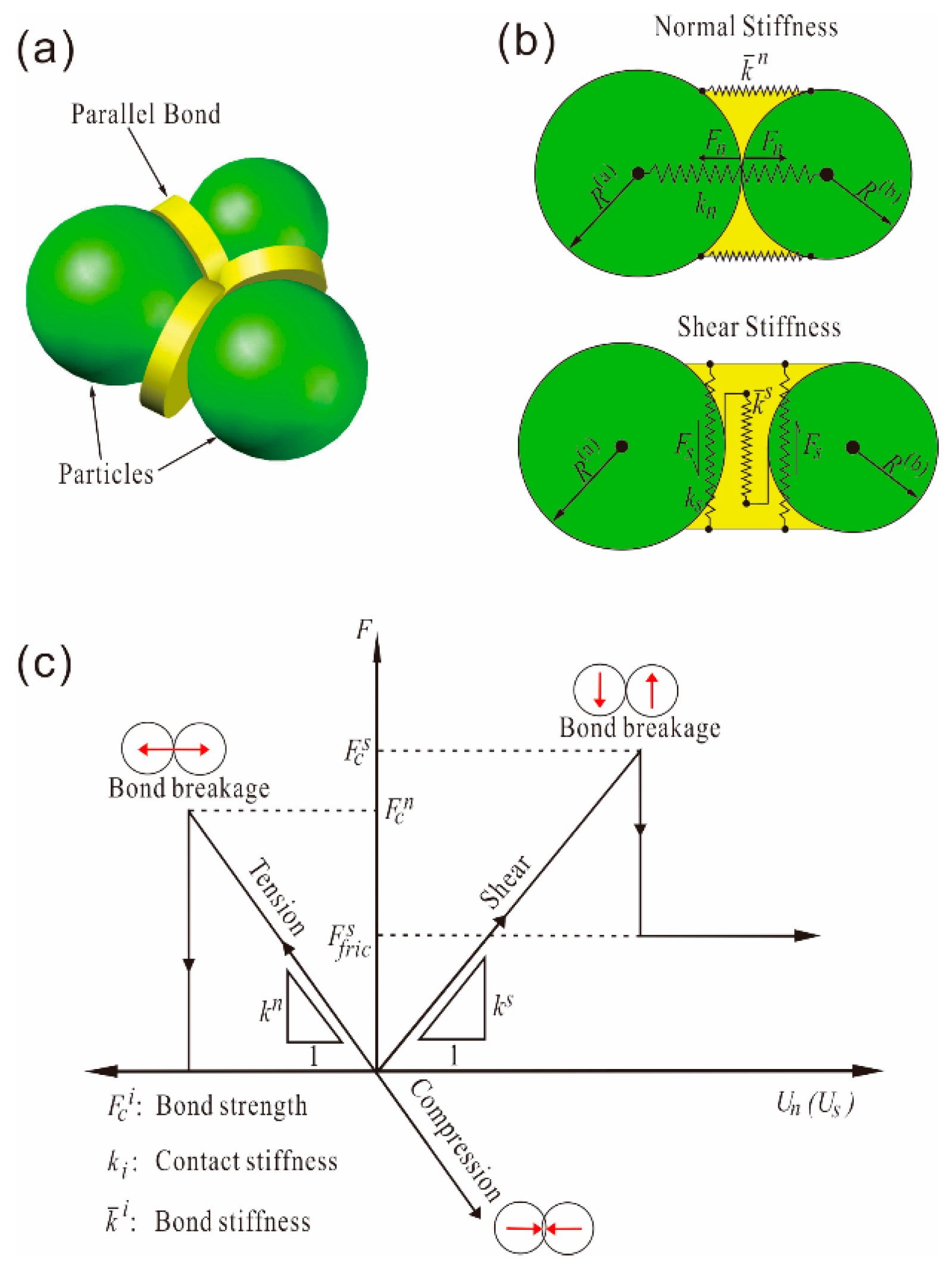
The Particle Flow Code (PFC) is another typical DEM based on the bonded particle method (BPM) [
44]. Compared with UDEC, PFC modeling of hydraulic fracturing allows not only fluid flow through fractures, but also fluid leak-off into the rock matrix. In recent years, PFC has been widely applied in geomechanics to model the failure processes of geomaterials and hydraulic fracturing [
18,
23,
24,
45,
46,
47,
48,
49,
50]. Zhao and Young [
18] validated the 2-Dimension Particle Flow Code (PFC
2D) for modeling hydraulic fracturing. Shimizu et al. [
47] conducted a series of hydraulic fracturing simulations in competent rock by using flow-mechanically coupled PFC
2D code and investigated the influence of the fluid viscosity and particle size distribution. Their results show that tensile cracks are dominantly generated in hydraulic fracturing process, while the energy from shear type acoustic emission is larger than from tensile types. After fracture creation, the velocity of the fluid infiltrating the fracture highly depends on the viscosity of the fluid. Eshiet et al. [
48] employed PFC
2D to model the pressure development and the subsequent fracturing and/or cavity propagation of bulk rock and sand, respectively, considering fluid flow based on the Navier-Stokes equation of an incompressible fluid with contact density. Yoon et al. [
49] used PFC
2D to study seismicity during the development of an Enhanced Geothermal System by fluid injection deep underground and simulated multistage hydraulic fracturing processes in a fractured reservoir. They then investigated the optimization of a hydraulic fracture network according the stress shadow [
50]. Zhou et al. [
23,
24,
25] studied hydraulic fracturing processes in isotropic and laminated reservoirs based on a modified fluid-mechanically coupled mechanism, and this model has been validated by comparing numerical values of breakdown pressures against analytical solutions. In addition, some influence factors on the driven fracture patterns and geometries such as the fluid viscosity, fluid injection rate, and the in situ stress state were analyzed.
Although the PFC has been used in hydraulic fracturing studies as mentioned above, the research into the details of interactions between hydraulic fractures and natural fractures is less reported. In this paper, using the laboratory experimental results of Zhou et al. [
12] as a comparison, the details of interactions between hydraulic fractures and natural fractures are studied by PFC
2D based on our fluid-mechanically coupled code [
23,
24]. Firstly, the simulation method is introduced and summarized, including the Particle Flow Code, the Smooth Joint Model, and the fluid-mechanical coupling mechanism in bonded granular matrix. Secondly, the numerical model is set up and the microscale parameters are calibrated according to the mechanical properties of the laboratory sample (cement plaster). Thirdly, a series of numerical simulations is carried out for comparison with the experimental results and to analyze the influence of approach angle and differential stress on the interaction between hydraulic and natural fractures. Finally, the influence of the permeability of natural fractures on the interaction is analyzed.
4. Modeling Results of Interactions between Hydraulic Fractures and Natural Fractures
4.1. Comparison with Laboratory Experimental Results
In the experimental works of Zhou et al. [
12], three interaction types have been observed under tri-axial stress states, including Crossed, Dilated, and Arrested type. The characteristics of the three interaction types in laboratory experiments are summarized as follows.
Crossed (Experiment): A natural fracture is crossed by a hydraulic fracture.
Dilated (Experiment): A natural fracture is arrested by an opening and dilating natural fracture.
Arrested (Experiment): A natural fracture is arrested by a shear slippage natural fracture with no dilation and by fluid flow in the natural fracture.
A series of hydraulic fracturing models were performed in two-dimensional stress states to investigate the interactions between hydraulic fractures and natural fractures, considering that the viscosity of the fracturing fluid is 1.0 × 10
−3 Pa·s and the rate of injection is 2.0 × 10
−4 m
3/s/m. Also, in our modeling (
Table 3,
Table 4 and
Table 5), there are three basic scenarios of interaction between hydraulic fractures and natural fractures, which are similar to those in laboratory experiments. The details of the interaction processes are described in the following.
Crossed (Modeling): A hydraulic fracture initiates and propagates along the direction of maximum principle stress, crosses the pre-existing natural fracture at the interaction with no or little fracturing fluid leaking off into it, and continues to propagate with no diversion from the original propagation direction.
Arrested (Modeling): A hydraulic fracture initiates and propagates along the direction of maximum principle stress; as the hydraulic fracture approaching the natural fracture, the natural fracture slips due to the deformation caused by the near-tip stress field of the hydraulic fracture, and a lack of fluid flow in the damaged natural fracture; when the hydraulic fracture encounters the natural fracture, the fracturing fluid leaks off into the damaged natural fracture quickly; and the hydraulic fracture is arrested by the damaged natural fracture, which becomes a part of the hydraulic fracture. Lastly, the hydraulic fracture restarts at one tip of the natural interface, with its orientation rerouted from the dip direction of the natural fracture to the direction of maximum principle stress.
Dilated (Modeling): Initially, the hydraulic fracture propagates along the direction of maximum principle stress; before the hydraulic fracture encounters the natural fracture, no or limited local shear slippage takes place in the natural fracture; while the hydraulic fracture encounters the natural fracture, the fracturing fluid penetrates into the natural fracture and dilates it, which results in shear slippage of the natural interface by decreasing the effective stress while the pore pressure increases at the intersection; and the hydraulic fracture is arrested by the damaged natural fracture, and it will reinitiate at the tip of the natural fracture or a weak point where the tensile stress is larger than the bond tensile strength.
Table 3,
Table 4 and
Table 5 present the modeling examples of the interactions between hydraulic fractures and natural fractures compared with the experimental results under different coefficients of friction of the natural fracture. Moreover, the figures, including the fracture patterns and pore-pressure distributions at two different times, are shown in
Table 3,
Table 4 and
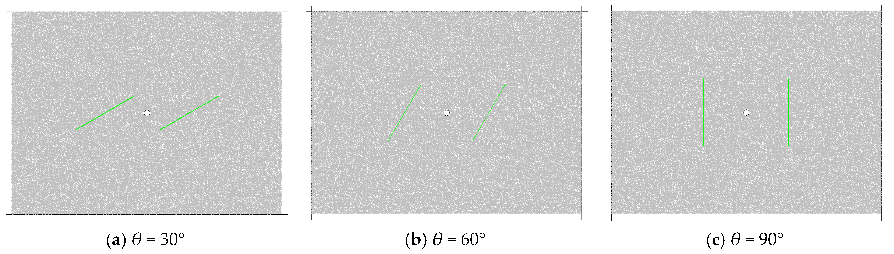
Table 5. In the figures, the original parallel natural fractures are shown by green lines. The red short line represents a tensile crack in the cement material, and the black short lines are the damaged part of the natural fractures under shear slippage. The pore-pressure in each fluid domain is presented by a solid blue circle, the size of which is related to the magnitude of the pore-pressure.
Based on the evolution of fracture patterns and pore-pressure distributions, the interaction types in our modeling were also summarized and listed in
Table 3,
Table 4 and
Table 5, and they agreed well with the experimental results, except for the Type III pre-existing interfaces. This exception can be attributed to the fact that the thickness of Type III pre-existing interfaces is significantly larger than the thickness of the two other types, which results in a permeability increase. In our modeling, the pre-existing natural fracture was crossed by the hydraulic fracture at high differential stress and angles of approach of 60° or greater, while the pre-existing natural fracture with low shear strength was arrested at angles of approach of 30°. In addition, an interesting phenomenon has been found, which is that combined forms of the three basic interaction types (Crossed, Arrested, and Dilated type) exist in several simulations.
Thus, according to the modeling results, we can arrive at a basic conclusion that the approach angle, in situ differential stress, and the permeability of natural fractures affect the interactions between hydraulic fractures and natural fractures. The influence will be discussed in following sections.
4.2. The Influence of Approach Angle and In-Situ Differential Stress
From previous studies, it is known that the interaction between hydraulic and natural fractures is a complex process, which is related to lots of influence factors such as the formation rock mechanical properties, the strength of the natural fractures, the approach angle, in situ stress, and the permeability of natural fractures. According to the scenarios described in the preceding section, the influence of the approach angle and in situ stress are further studied in this section, with the intention to provide a basic conclusion for selecting stimulation methods in the hydraulic fracturing process.
A series of hydraulic fracturing models were performed considering in situ differential stress changing from 2 MPa to 8 MPa and approach angles varying from 30° to 90°, while the maximum principle stress was kept at 10 MPa in the horizontal direction. In addition, the cohesion and tensile strength of pre-existing fractures were both set to a negligible value of 0.05 MPa. The stimulation parameters were the same as in
Section 4.1.
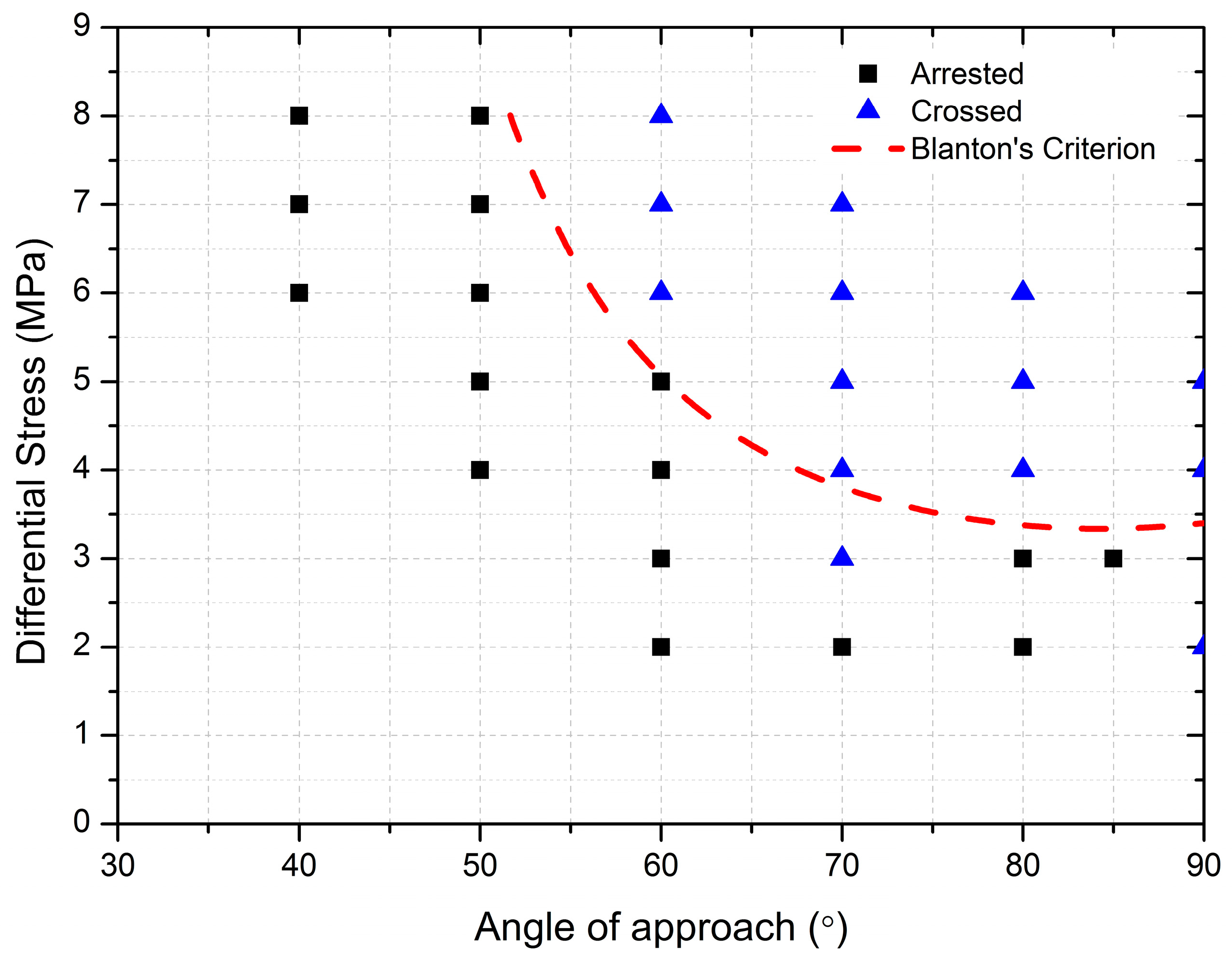
According to the general mechanism of interaction between hydraulic fractures and natural fractures, the Dilated type and Arrested type are collectively called Arrested type.
Figure 7 shows the interaction results related to different in situ differential stresses and approach angles. It can be found that the natural fracture is more favorable for opening and diverting fracturing fluid under low approach angles and low differential stresses, which results in the propagation of a hydraulic fracture along the natural fracture and its re-initiation at a weak point or the tip of the natural fracture. On the contrary, under high approach angles and high differential stresses, the hydraulic fracture tends to cross the pre-existing natural fracture. Moreover, the series of modeling results under different approach angles and in situ stress states indicated very good agreement compared to the analytical results based on Blanton’s criterion [
9], except in a few cases (
Figure 7).
4.3. The Influence of Natural Fracture Permeability
In previous numerical modeling of and analytical research into the interaction between hydraulic fractures and natural fractures, the permeability of natural fractures was not taken into consideration [
9,
10,
11,
12,
14]. However, the experimental results in Zhou et al. [
12] showed that the influence of the permeability of natural fractures on the interaction between hydraulic fractures and natural fractures cannot be omitted. For example, the thickness of the Type III pre-existing interfaces is significantly larger than that of the two other types, which results in the effect that fracturing fluid more easily leaks off into the natural fracture and causes dilation.
The permeability of Type III pre-existing interfaces was assumed to be 100 mD, which is three orders of magnitude higher than the original value.
Table 6 presents the summary of the modeled results of interaction between hydraulic fractures and natural fractures. When the driven hydraulic fracture encountered the natural fracture, the fracturing fluid was subsequently diverted into the natural fracture. Obviously, the effective normal stress acting on two walls of a natural fracture decreased owing to an increase in pore-pressure and a decrease in shear resistance force. If shear resistance is lower than shear force, a microscale shear crack will be initiated. Comparing the fracture patterns and pore-pressure distributions of the figures in
Table 5 and
Table 6, it can be observed that the interactions between hydraulic fractures and natural fractures also depend on the permeability of natural fractures. At this time, the interaction types of the modeling agree well with the related experimental results at different conditions.


