
Influence of Prewhirl Angle and Axial Distance on Energy Performance and Pressure Fluctuation for a Centrifugal Pump with Inlet Guide Vanes


State Key Laboratory of Hydroscience and Engineering, Tsinghua University, Beijing 100084, China
*
Author to whom correspondence should be addressed.
Energies 2017, 10(5), 695; https://doi.org/10.3390/en10050695
Submission received: 16 February 2017
/
Revised: 10 May 2017
/
Accepted: 12 May 2017
/
Published: 15 May 2017
Abstract
:The energy performance and pressure fluctuations in a centrifugal pump with inlet guide vanes (IGVs) are investigated experimentally and numerically in a prewhirl angle range of −24° to 24° and in an axial distance range of 280 mm, 380 mm, and 460 mm. The reliability and accuracy of the numerical method are validated by the satisfactory agreement between the experimental data and numerical results. Prewhirl regulation with IGVs can significantly increase the energy performance and broaden the efficient operation range for the centrifugal pump due to the improvement of flow pattern at the impeller inlet. The prewhirl angle has an obvious impact on pump energy performance, and the maximum amplitudes of pressure fluctuations on the blade leading edge of the pressure and suction sides decrease by 69% and 89%, respectively. The axial distance has a slight impact on pump energy performance, but the maximum amplitudes of pressure fluctuations drop by 35.4% on the blade leading edge of pressure side when the axial distance extends from 280 mm to 460 mm.
1. Introduction
The inlet guide vanes are widely used in operation adjustment of industrial centrifugal compressors, especially in the case of a slight pressure variation at constant rotational speed. IGVs for centrifugal compressors have been thoroughly studied both experimentally and numerically. Zhou et al. [1] investigated the unsteady IGVs–impeller–diffuser interaction in a centrifugal compressor, and found that the unsteadiness in the diffuser with negative IGVs angles was larger than that with positive prewhirl angles. Coppinger and Swain [2] demonstrated the test techniques and resulting analyses of the existing design of inlet guide vanes systems for industrial centrifugal compressor, and conducted some predictions of the performance of the improved IGVs system design. Mohseni et al. [3] presented three different novel IGVs designs for centrifugal compressors and the results showed that the s-cambered profile was preferred for applications with positive prewhirl. Cui [4] and Oro et al. [5] focused on the unsteady flow for centrifugal compressors with inlet guide vanes, and analyzed the unsteady flow structures, periodic interaction, and wake transport. Johnston and Fleeter [6] performed experiments on pressure and velocity fields of wake-induced by IGVs for three IGV-rotor axial distances. The results showed that higher harmonics of the vertical gust component for IGV wakes decayed at a uniform rate due to viscous diffusion. The IGV-rotor axial distance had minimal effect on the velocity deficit of IGVs’ wake. Fukutomi and Nakamura [7] studied the energy performance and internal flow of a cross-flow fan with inlet guide vanes, with consideration of the effect of IGVs angle and length.
However, compared with centrifugal compressors, the prewhirl regulation of IGVs is seldom adopted in centrifugal pumps, due to the inevitable pressure loss and potential deterioration of cavitation performance caused by inlet guide vanes. However, related studies demonstrated that the prewhirl regulation would widen the high efficiency zone and improve the energy performance for off-design conditions with the proper prewhirl angle and axial distance [8]. Tan et al. [9,10,11,12] proposed a new hydraulic design method of three-dimensional guide vanes for centrifugal pumps and investigated the influence of prewhirl regulation by inlet guide vanes on energy performance, cavitation performance, and unsteady flow characteristics in a centrifugal pump by numerical and experimental studies. Ahmed et al. [13] realized an efficiency enhancement by 2% for a centrifugal water pump under design condition, and the efficiency reached a maximum at the pre-whirl angle of 60°. Chan et al. [14] numerically studied the effects of IGVs on the flow pattern and shear stress in a centrifugal blood pump, and found that the IGV effected the inlet velocity triangles, and further contributed to a drop in the pressure head. Ferro et al. [15] presented a fast design method for the inlet guide vanes of low-cost mini hydraulic bulb turbines and validated it by traversing measurements along the circumferential and radial directions with a five-hole probe.
The rotor-stator interaction between IGVs, impeller, and volute in a pump generates pressure fluctuations and induces operation instability [16]. Therefore, related studies have been conducted to sufficiently reveal the incentive, distribution, and intensity of pressure fluctuations in pumps. Yang et al. [17] investigated the effects of the radial gap between impeller outlet and volute tongue on efficiency and pressure fluctuations of a pump as turbine, and found that the rotor stator interaction of impeller and volute would cause high-frequency fluctuations in the volute and low-frequency fluctuations in the impeller. Spence et al. [18] investigated the pressure fluctuations in a centrifugal pump by numerical methods and industrial tests. The results showed that the regions in the pump experiencing the largest pressure fluctuations are located at the impeller outlet, with large fluctuations also present in the volute at positions in close proximity to the cutwater or splitter. Zhang et al. [19] analyzed pressure pulsation signals measured from shutoff to maximum operating conditions using an auto-power spectrum algorithm and the root mean square (RMS) method, and found that a sloped volute could significantly decrease the pressure pulsation level. Tan et al. [20,21] studied the pressure fluctuations in a centrifugal pump under non-cavitation and cavitation conditions, and the result showed that cavitation would greatly strengthen the amplitudes of the pressure fluctuations. The above results show that the dominant frequencies of pressure fluctuations in a centrifugal pump are closely related to the rotor-stator interaction between the impeller and volute. The amplitudes of the pressure fluctuations are significantly enlarged under cavitation conditions.
Although some studies have been conducted on the prewhirl regulation of IGVs in centrifugal pumps, the relationship among prewhirl angle, axial distance, and pump performance has not been fully revealed, which is of significant importance on the energy performance and operation instability for a centrifugal pump. Thus, a systematic investigation on the influence of the prewhirl angle and axial distance on the energy performance and pressure fluctuation for a centrifugal pump with inlet guide vanes is conducted in the present research.
2. Physical Model and Computational Mesh
2.1. Physical Model of Centrifugal Pump
The tested centrifugal pump is a conventional single suction centrifugal pump, and the main design parameters of the centrifugal pump are listed in Table 1. Six IGVs are circumferential, evenly installed in the suction pipe. The axial distance is defined as the distance between the central line of IGVs and the impeller inlet. The prewhirl is defined as a positive value when the prewhirl direction of IGVs is the same as the direction of impeller rotation; otherwise, the prewhirl is negative. In the present work, 16 computational cases are built for suction pipes without IGVs and with IGVs at different prewhirl angles (0°, ±12°, ±24°) with three axial distances (280 mm, 380 mm, 460 mm).
The test apparatus for the centrifugal pump consists of (1) an exhaust (Sections 1–3), (2) a pump (Sections 4–7), and (3) a water supply (Sections 8–10), as shown in Figure 1. The computation domain consists of three parts: a suction pipe without or with IGVs, an impeller, and a volute for the centrifugal pump.
2.2. Computational Domain and Mesh
Figure 2 shows the computational domain and mesh of the centrifugal pump with IGVs. The structural hexahedron meshes are employed for the impeller and IGVs, and the local mesh encryptions are applied near the blade and vane surfaces as shown in Figure 2d,e. To investigate the pressure fluctuations in the impeller and volute for the centrifugal pump, 10 monitoring points are set in the impeller and 13 monitoring points are set in the volute, as shown in Figure 2f. Monitoring points in the impeller are named as PS1–PS5 and SS1–SS5 on the blade pressure and suction sides from the inlet to the outlet, and monitoring points in the volute are named as V1–V12 from the volute tongue to the outlet.
3. Numerical Method and Setting
3.1. Numerical Method
In the present work, the computation fluid dynamics software CFX 14.5 (ANSYS Inc., Pittsburgh, PA, USA) and the RNG k-ε turbulence model are employed. The boundary conditions are set as: the total pressure at pump inlet, the mass flow rate at the pump outlet, and no slip wall at the walls. The methods of frozen-rotor and transient-rotor-stator are applied to couple the rotational and stationary domains for steady and unsteady calculations, respectively [22,23,24]. The relative position between the stable suction pipe and the volute and the rotational impeller remains unchanged in the frozen-rotor method, while it varies according to the angular velocity of the impeller in the transient-rotor-stator method.
Taking the results of the steady simulation as the initial flow field, the unsteady calculation is conducted to investigate the unsteady flow and pressure fluctuations in the centrifugal pump. The convergence criterion is set as that the value of the root mean square residual is below 1 × 10⁻⁵.
3.2. Independence Test of Mesh Density and Time Step
To validate the independence of the mesh density, four sets of meshes with mesh elements from 1,709,954 to 3,165,914 are employed to conduct calculations on the centrifugal pump without IGVs. As shown in Table 2, the variation of pump head and efficiency is minuscule with ΔH/H1 ≤ 0.0065 and Δη/η1 ≤ 0.0006. Therefore, comprehensively considering the calculation cost and accuracy, Mesh 2 with 2,155,166 elements is chosen in the following calculations.
The rotation period of impeller for the centrifugal pump is T = 60/1450 s = 0.04137931 s. Three different time steps are set as 1.0776 × 10⁻⁴ s, 2.1552 × 10⁻⁴ s, and 4.3103 × 10⁻⁴ s, which are 1/384T, 1/192T, and 1/96T, respectively, to validate independence of the time step. Figure 3 presents the time histories of pressure at two monitoring points PS4 and V0, which are located at the blade pressure side and volute tongue, respectively. The results show that the predicted pressure curves are highly consistent at both positions, illustrating that the influence of time step Δt on the simulation result is negligible. Considering both the calculation cost and accuracy, a time step of 2.1552 × 10⁻⁴ s is chosen in the following calculations.
4. Results and Discussion
4.1. Simulation Accuracy Validation
The experiment of the test pump was carried out at Dongfang Pump Co., Ltd. (Shanghai, China). Through uncertainty analysis of the system, the comprehensive error of the pump performance measurement is estimated within ±0.358%. To validate the reliability and accuracy of the numerical method, the steady calculations are carried out under five working conditions and five prewhirl angles with the axial distance of 380 mm. Figure 4 shows the comparison of performance curves of head and efficiency between the experimental and simulation results. The simulation performance curves for all cases are in remarkable agreement with the experimental results, with the maximum relative errors at small flow rates smaller than 5.0%. For flow rates around the best efficiency point, the maximum relative errors of pump efficiency for different prewhirl angles are smaller than 0.2%. Additionally, there is a difference between the computational model and experimental model, which is the axial mounting bracket in the suction pipe. It is validated by numerical simulation that the impact of the bracket on pump performance can be neglected.
4.2. Influence of Prewhirl Angle of IGVs on Pump Performance
Figure 5 shows the variation of head and efficiency for the centrifugal pumps without IGVs and with IGVs for five prewhirl angles with the axial distance of 380 mm. With the prewhirl angle decreasing from 24° to −24°, the pump head dramatically increases at all flow rates, which demonstrates the pump head is significantly influenced by the prewhirl angle γ. The reason is that when the prewhirl angle decreases from a positive angle to a negative angle, the circumferential velocity at the impeller inlet will also decrease from a positive value to a negative value, thus causing the increase of the pump head according to the Euler equation.
It can be illustrated from Figure 5b that all efficiencies of pumps with prewhirl regulation are higher than that without IGVs when the flow rate is below 380 m3/h. For low flow rates below 280 m3/h, the efficiencies of pumps with positive prewhirl angles are higher than those with negative prewhirl angles. However, for large flow rates beyond 360 m3/h, the efficiencies of pumps with positive prewhirl angles are lower than those with negative prewhirl angles. The reason is that, at low flow rates, the positive prewhirl suppress the second flow in impeller, and improve the pump efficiency. Figure 6 shows the pressure distribution and surface streamlines on a circumferential section of D = 200 mm in a blade-to-blade passage at Q = 200 m3/h. It can been seen that the pressure at the section for γ = −24° is higher than that for γ = 24°, and this phenomenon corresponds with the pump heads for different prewhirl angles. There is an obvious second flow at this section, and the intensity of the second flow is suppressed when the prewhirl angle turns from γ = −24° to γ = 24°, while at large flow rate the impact loss of IGVs with positive prewhirl angles greatly increases, and then reduces the effect of prewhirl regulation on pump efficiency.
Generally, IGVs can significantly increase the energy performance of the centrifugal pump, and the effect is strongly influenced by the prewhirl angle. By changing the prewhirl angle at different flow rates, the efficient operation range of the centrifugal pump can be effectively broadened.
To reveal the flow details in pumps without and with IGVs, the three-dimensional vortex defined by the Q criterion is presented in the downstream view in Figure 7 and Figure 8, based on the simulation results at the designed flow rate. The Q criterion is the second invariant of the velocity gradient tensor, which is defined as . Compared with the centrifugal pump without IGVs, the vortex intensity significantly decreases and the vortex distribution is more uniform in pumps with prewhirl regulation. When the prewhirl angle decreases from 24° to −24°, the vortex core region gradually increases on the blades, as well as in the vicinity of the blade leading edge, while the vortex intensity in the suction pipe decreases at first, and then increases with a relative range. The above analysis indicates that, with the consideration of vortex intensity in the impeller and suction pipe, prewhirl regulation with IGVs remarkably optimizes the flow pattern in the impeller and makes it more homogeneous, which explains the efficiency improvement at the designed flow rate, as shown in Figure 5b. For different prewhirl angles, the positive prewhirl shows better optimization effects than the negative prewhirl, but the increase of the positive prewhirl angle also leads to greater energy loss on the guide vanes. Consequently, comprehensively considering the energy loss in the impeller and suction pipe, the pump with prewhirl regulation of γ = 0° reaches the highest efficiency at the designed flow rate, as shown in Table 3.
Taking the steady calculation results as the initial flow field, the transient simulation under the designed flow rate is conducted for 12.5 impeller revolutions. The data of the last 10 revolutions is used to construct the fast Fourier transform (FFT), so the frequency characteristics of the pressure fluctuations on the monitoring points are obtained.
Table 4 shows the dominant frequencies and maximum amplitudes of the pressure fluctuations on the monitoring points in the impeller and volute. It can be seen that all frequencies of the pressure fluctuations for pumps without and with IGVs are the integer times of the impeller rotating frequency fi, demonstrating that the impeller rotation and the rotor-stator interaction between the impeller and volute are the crucial factors for the frequency characteristics of the pressure fluctuations.
Except for γ = 24° on SS1 and SS3, the dominant frequencies of the pressure fluctuations on the blade are all the same for pumps with and without IGVs. Compared with pumps without IGVs, the maximum amplitudes of the pressure fluctuations on PS1, SS1, and SS3 in pumps with IGVs significantly decrease, with maximum drops of 69%, 89%, and 58%, respectively. For all pumps without and with IGVs, the dominant frequencies on PS3, PS5, and SS5 remain the same, and the variation of maximum amplitudes is very small. For different prewhirl angles, the maximum amplitudes on PS1 and SS3 at γ = −24° are larger than those at γ = 0° and γ = 24°, which can be attributed to the interaction between the negative prewhirl regulation and the positive rotation in the impeller. For γ = 24°, the dominant frequencies on SS1 and SS3 change to 2fi and 5fi, which are related to the strong positive prewhirl effect shown in Figure 7d. The above analysis indicates that prewhirl regulation makes the flow state at the impeller inlet more homogeneous and further optimizes the pressure fluctuation characteristics on the blade. The influence of the prewhirl angle on pressure fluctuations is related to the interaction between the prewhirl effect at the impeller inlet and the impeller rotation.
For pressure fluctuations on V1, V3, V5, V7, and V9 in the volute, the dominant frequencies are all 6fi, which is the blade passing frequency. Similar with PS3, PS5, and SS5, the maximum amplitudes on monitoring points in the volute nearly remain unchanged, demonstrating that the influence of the prewhirl angle on pressure fluctuations in the volute is very slight. It can be concluded that the influence level of prewhirl regulation and prewhirl angle on pressure fluctuations decreases from the leading edge of blade to the volute for the centrifugal pump.
To evaluate pressure fluctuation energy in the pumps with and without IGVs, the RMS method is applied in Equations (1) and (2):
where N is the sample number, Pi is the pressure at each time step, and is the mean value of pressure.
Based on 1920 data points in the last 10 revolutions of the numerical simulation, the pressure RMS values in the unsteady calculation are obtained. Table 5 shows the pressure RMS values on monitoring points in the impeller and volute of pumps with and without IGVs. The variation trends of the pressure RMS values in pumps with different prewhirl angles are similar with those of the maximum amplitudes of pressure fluctuations in Table 4. Compared with pumps without IGVs, the pressure RMS values on PS1, SS1, and SS3 in pumps with IGVs decrease by 58%, 83%, and 43%, respectively. This shows that the IGVs significantly weaken the pressure fluctuation energy in the pump.
Figure 9 shows pressure gradient and turbulence intensity distribution on blade-to-blade surfaces in the middle span of the impeller. The turbulence intensity, also often referred to as turbulence level, is defined as:
where k is the turbulence kinetic energy and U is the mean velocity. Through the user-defined function in CFX 14.5, the turbulence intensity I is defined according to Equation (3), thus, the turbulence intensity distribution in the pump is obtained.
Compared with Figure 9a, the low pressure gradient regions in Figure 9b extend along the flow direction and the high pressure gradient regions near the leading edge significantly decrease, demonstrating that the pressure gradient in an impeller with a positive prewhirl angle is much lower than that in an impeller with a positive prewhirl angle, especially for regions near the leading edge of the blade. As Figure 9c,d show, the turbulence intensity on the whole blade suction side and blade surface side near the leading edge dramatically decreases when the prewhirl angle changes from −24° to 24°, illustrating that the unsteady flow field in regions near the leading edge of blade for γ = 24° is more disordered than that for γ = −24°. It can be concluded that a positive prewhirl angle produces greater optimization effects on the flow state in the impeller than a negative prewhirl angle at the designed flow rate, and the optimization of the flow field around points PS1, SS1, and SS3 significantly reduces the pressure fluctuation amplitudes, as shown in Table 4 and Table 5.
4.3. Influence of Axial Distance on Pump Performance
The axial distance DA is defined as the distance between the central line of IGVs and the impeller inlet. To investigate the influence of the axial distance on the energy performance and pressure fluctuation in pumps with IGVs, the steady and unsteady simulation under the designed flow rate are conducted in the present work.
Table 6 shows the comparison of pump efficiencies with axial distances of 280 mm, 380 mm, and 460 mm. The experimental results show that the highest efficiencies of pumps with different axial distances are 78.410% at DA = 280 mm for γ = −12°, 78.760% at DA = 380 mm for γ = 0°, and 78.560% at DA = 460 mm for γ = 0°. The simulation results show that the highest efficiencies are 78.871% at DA = 280 mm for γ = 0°, 78.894% at DA = 380 mm for γ = 0°, and 78.877% at DA = 460 mm for γ = 0°, respectively. Therefore, the axial distance of 380 mm is the recommended axial distance for the present centrifugal pump and IGVs.
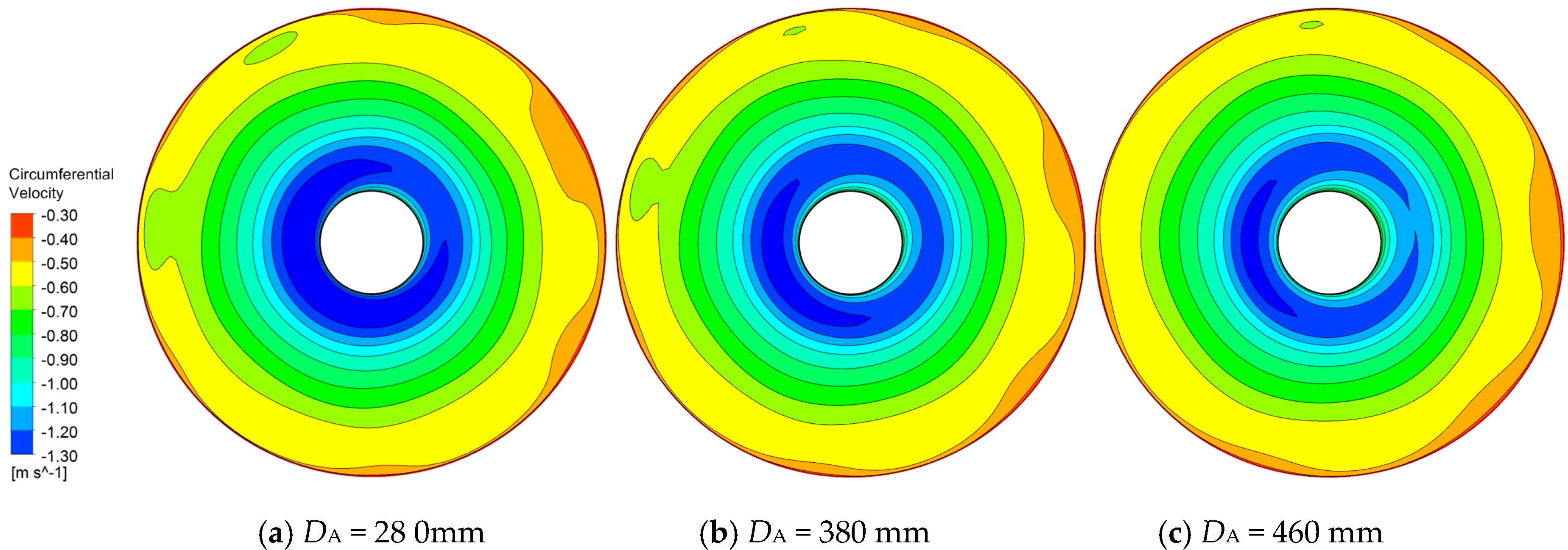
Figure 10 shows circumferential velocity distribution at the impeller inlet with different axial distances for γ = 0° at the designed flow rate. Due to the positive prewhirl effect for γ = 0°, the value of the circumferential velocity is negative, meaning that the rotation direction of the fluid is the same as the impeller rotation direction. For DA = 280 mm, the flow at the impeller inlet is not homogeneous enough at the impeller inlet compared with Figure 10b,c, which may lead to the disordered flow state in the impeller. For DA = 460 mm, the fluid viscosity through the long suction pipe decreases the velocity circulation at the impeller inlet, thus weakening the prewhirl effect, as shown in Figure 10c. Therefore, the axial distance of 380 mm is a proper choice to improve the energy performance of the centrifugal pump with IGVs.
To study the pressure fluctuations for different axial distances, the unsteady simulation under the designed flow rate is carried out, and the frequency characteristics of the pressure fluctuations are obtained by the fast Fourier transform.
Table 7 shows the dominant frequencies and maximum amplitudes of pressure fluctuations on monitoring points on the impeller blade and in the volute. The results show that, for different axial distances, the dominant frequencies of pressure fluctuations on most monitor points remain the same, and the variation of the maximum amplitudes on PS3, PS5, and SS5 is very slight. The maximum amplitudes of pressure fluctuations on PS1, SS1, and SS3 gradually decrease when the axial distance increases from 280 mm to 460 mm, indicating that the influence of the axial distance on pressure fluctuations in the impeller concentrates on the region near the blade leading edge. For PS1, on the blade leading edge of the pressure side, the maximum amplitude of the pressure fluctuation reduces from 1697 pa to 1111 pa in a drop of 35%. This can be attributed to the decrease of the axial distance leading to the deterioration of the homogeneous degree at the impeller inlet and further influences the flow pattern in the impeller, as shown in Figure 10.
As Table 7 shows, both the dominant frequencies and maximum amplitudes of pressure fluctuations in the volute nearly remain unchanged with the increase of the axial distance, demonstrating that the influence of the axial distance on pressure fluctuations in the volute can be neglected.
The above analysis shows that the influence of the axial distance on pressure fluctuations in the centrifugal pump decreases from the leading edge of the blade to the volute. The axial distance of 460 mm is most beneficial to reduce the pressure fluctuations in the pump, but the influence level and action area are quite limited, especially for DA = 460 mm and DA = 380 mm. Therefore, the axial distance of 380 mm is the comprehensive optimal selection for the centrifugal pump with IGVs, with the consideration of energy performance and operation stability.
5. Conclusions
The influence of prewhirl angle and axial distance on energy performance and pressure fluctuation for a centrifugal pump with IGVs is conducted experimentally and numerically in the present work, and the main conclusions can be drawn as follows:
- (1)
- Prewhirl regulation with IGVs can remarkably increase the energy performance of the centrifugal pump in a wide region, and the effect is strongly influenced by the prewhirl angle.
- (2)
- Prewhirl regulation makes the flow state at the impeller inlet more homogeneous, and further optimizes the pressure fluctuation characteristics in the impeller. The influence of prewhirl regulation on pressure fluctuations is related to the interaction between the prewhirl effect at the impeller inlet and the impeller rotation.
- (3)
- The axial distance between the IGVs and impeller has an impact on flow pattern at the impeller inlet, and further affects the energy performance and pressure fluctuations in the centrifugal pump. The effect of the axial distance on energy performance is slight, while, for the maximum amplitudes of pressure fluctuations, they drop by 35.4% on the blade leading edge of the pressure side when the distance extends from 280 mm to 460 mm.
Acknowledgments
This work has been supported by the Tsinghua University Initiative Scientific Research Program (grant number 2014z21041), the Beijing Natural Science Foundation (grant number 3164045), the National Natural Science Foundation of China (grant numbers 51579006, 51679122), and the Open Research Subject of Key Laboratory of Fluid and Power Machinery, Ministry of Education (grant number szjj2015-021).
Author Contributions
Yabin Liu and Lei Tan conceived and designed the experiments and simulations; Yabin Liu, Ming Liu, Yue Hao and Yun Xu performed the experiments and simulations; Yabin Liu and Lei Tan analyzed the data and wrote the paper.
Conflicts of Interest
The authors declare no conflicts of interest.
References
- Zhou, L.; Fan, H.; Wei, W.; Cai, Y.H. Experimental and numerical analysis of the unsteady influence of an inlet guide vane. Proc. Inst. Mech. Eng. Part C 2011, 226, 660–680. [Google Scholar] [CrossRef]
- Coppinger, M.; Swain, E. Performance prediction of an industrial centrifugal compressor inlet guide vane system. Proc. Inst. Mech. Eng. Part A 2000, 214, 153–164. [Google Scholar] [CrossRef]
- Mohseni, A.; Goldhahn, E.; Van den Braembussche, R.A.; Seume, J.R. Novel IGV designs for centrifugal compressors and their interaction with the impeller. J. Turbomach. 2012, 134, 2019–2029. [Google Scholar] [CrossRef]
- Cui, M. Unsteady flow around suction elbow and inlet guide vanes in a centrifugal compressor. In ASME Turbo Expo 2004: Power for Land, Sea, and Air; American Society of Mechanical Engineers: New York, NY, USA, 2004; pp. 717–735. [Google Scholar] [CrossRef]
- Oro, J.; Diaz, K.; Morros, C.; Marigorta, E. Unsteady flow and wake transport in a low-speed axial fan with inlet guide vanes. J. Fluids Eng. 2007, 129, 1015–1029. [Google Scholar] [CrossRef]
- Johnston, R.; Fleeter, S. Inlet guide vane wakes including rotor effects. J. Fluids Struct. 2001, 15, 235–253. [Google Scholar] [CrossRef]
- Fukutomi, J.; Nakamura, R. Performance and internal flow of cross-flow fan with inlet guide vane. JSME Int. J. Ser. B 2005, 48, 763–769. [Google Scholar] [CrossRef]
- Tan, L.; Cao, S.; Wang, Y.; Zhu, B. Influence of axial distance on prewhirl regulation by the inlet guide vanes for a centrifugal pump. Sci. China Technol. Sci. 2012, 55, 1037–1043. [Google Scholar] [CrossRef]
- Tan, L.; Cao, S.; Gui, S. Hydraulic design and prewhirl regulation law of inlet guide vane for centrifugal pump. Sci. China Technol. Sci. 2010, 53, 2142–2151. [Google Scholar] [CrossRef]
- Tan, L.; Zhu, B.; Cao, S.; Bing, H.; Wang, Y. Influence of blade wrap angle on centrifugal pump performance by numerical and experimental study. Chin. J. Mech. Eng. 2014, 27, 171–177. [Google Scholar] [CrossRef]
- Tan, L.; Zhu, B.; Cao, S.; Wang, Y.; Wang, B. Influence of prewhirl regulation by inlet guide vanes on cavitation performance of a centrifugal pump. Energies 2014, 7, 1050–1065. [Google Scholar] [CrossRef]
- Wang, Y.; Tan, L.; Zhu, B.; Cao, S.; Wang, B. Numerical investigation of influence of inlet guide vanes on unsteady flow in a centrifugal pump. Proc. Inst. Mech. Eng. Part C 2015, 229, 3405–3416. [Google Scholar] [CrossRef]
- Ahmed, S.; Muiz, A.; Mubashir, A.; Ahmed, W. Efficiency enhancement of centrifugal water pump by using inlet guided vanes. Eur. J. Adv. Eng. Technol. 2016, 3, 1–4. [Google Scholar]
- Chan, W.; Wong, Y.; Yu, S.; Chua, L. A computational study of the effects of inlet guide vanes on the performance of a centrifugal blood pump. Artif. Organs 2002, 26, 534–542. [Google Scholar] [CrossRef] [PubMed]
- Ferro, L.; Gato, L.; Falcão, A. Design and experimental validation of the inlet guide vane system of a mini hydraulic bulb-turbine. Renew. Energy 2010, 35, 1920–1928. [Google Scholar] [CrossRef]
- Arndt, N.; Acosta, A.; Brennen, C.; Caughey, T. Experimental investigation of rotor-stator interaction in a centrifugal pump with several vaned diffusers. In Proceedings of the ASME 1989 International Gas Turbine and Aeroengine Congress and Exposition, Toronto, ON, Canada, 4–8 June 1989; V001T01A033. American Society of Mechanical Engineers: New York, NY, USA, 1989. [Google Scholar]
- Yang, S.; Liu, H.; Kong, F.; Xia, B.; Tan, L. Effects of the radial gap between impeller tips and volute tongue influencing the performance and pressure pulsations of pump as turbine. J. Fluids Eng. 2014, 136, 054501. [Google Scholar] [CrossRef]
- Spence, R.; Amaral-Teixeira, J. Investigation into pressure pulsations in a centrifugal pump using numerical methods supported by industrial tests. Comput. Fluids 2008, 37, 690–704. [Google Scholar] [CrossRef]
- Zhang, N.; Yang, M.; Gao, B.; Li, Z.; Ni, D. Experimental investigation on unsteady pressure pulsation in a centrifugal pump with special slope volute. J. Fluids Eng. 2015, 137, 061103. [Google Scholar] [CrossRef]
- Tan, L.; Zhu, B.; Cao, S.; Wang, Y.; Wang, B. Numerical simulation of unsteady cavitation flow in a centrifugal pump at off-design conditions. Proc. Inst. Mech. Eng. Part C 2014, 228, 1994–2006. [Google Scholar] [CrossRef]
- Tan, L.; Zhu, B.; Wang, Y.; Cao, S.; Gui, S. Numerical study on characteristics of unsteady flow in a centrifugal pump volute at partial load condition. Eng. Comput. 2015, 32, 1549–1566. [Google Scholar] [CrossRef]
- Qu, W.; Tan, L.; Cao, S.; Wang, Y.; Xu, Y. Numerical investigation of clocking effect on a centrifugal pump with inlet guide vanes. Eng. Comput. 2016, 33, 465–481. [Google Scholar] [CrossRef]
- Liu, Y.; Tan, L.; Hao, Y.; Xu, Y. Energy performance and flow patterns of a mixed-flow pump with different tip clearance sizes. Energies 2017, 10, 191. [Google Scholar] [CrossRef]
- Hao, Y.; Tan, L.; Liu, Y.; Xu, Y.; Zhang, J.; Zhu, B. Energy performance and radial force of a mixed-flow pump with symmetrical and unsymmetrical tip clearances. Energies 2017, 10, 57. [Google Scholar] [CrossRef]
Figure 1.
Schematic diagram of the experimental rig. 1: regulating valve; 2: turbine flowmeter; 3: pressure gauge; 4: motor; 5: composite torque detector; 6: centrifugal pump; 7: IGV; 8: vacuum gauge; 9: regulating valve; and 10: water tank.
Figure 1.
Schematic diagram of the experimental rig. 1: regulating valve; 2: turbine flowmeter; 3: pressure gauge; 4: motor; 5: composite torque detector; 6: centrifugal pump; 7: IGV; 8: vacuum gauge; 9: regulating valve; and 10: water tank.
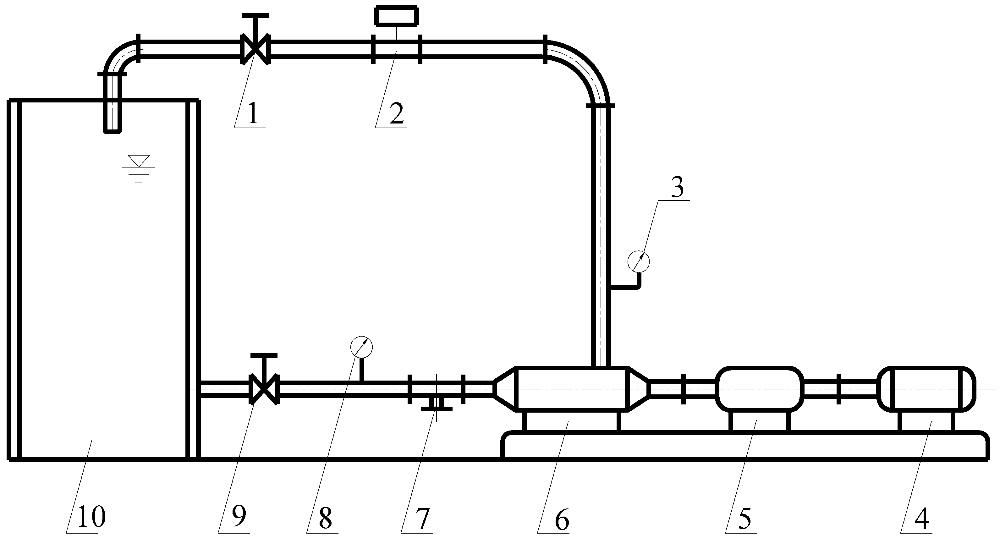
Figure 2.
Computation domain, mesh, and monitor points for the centrifugal pump.
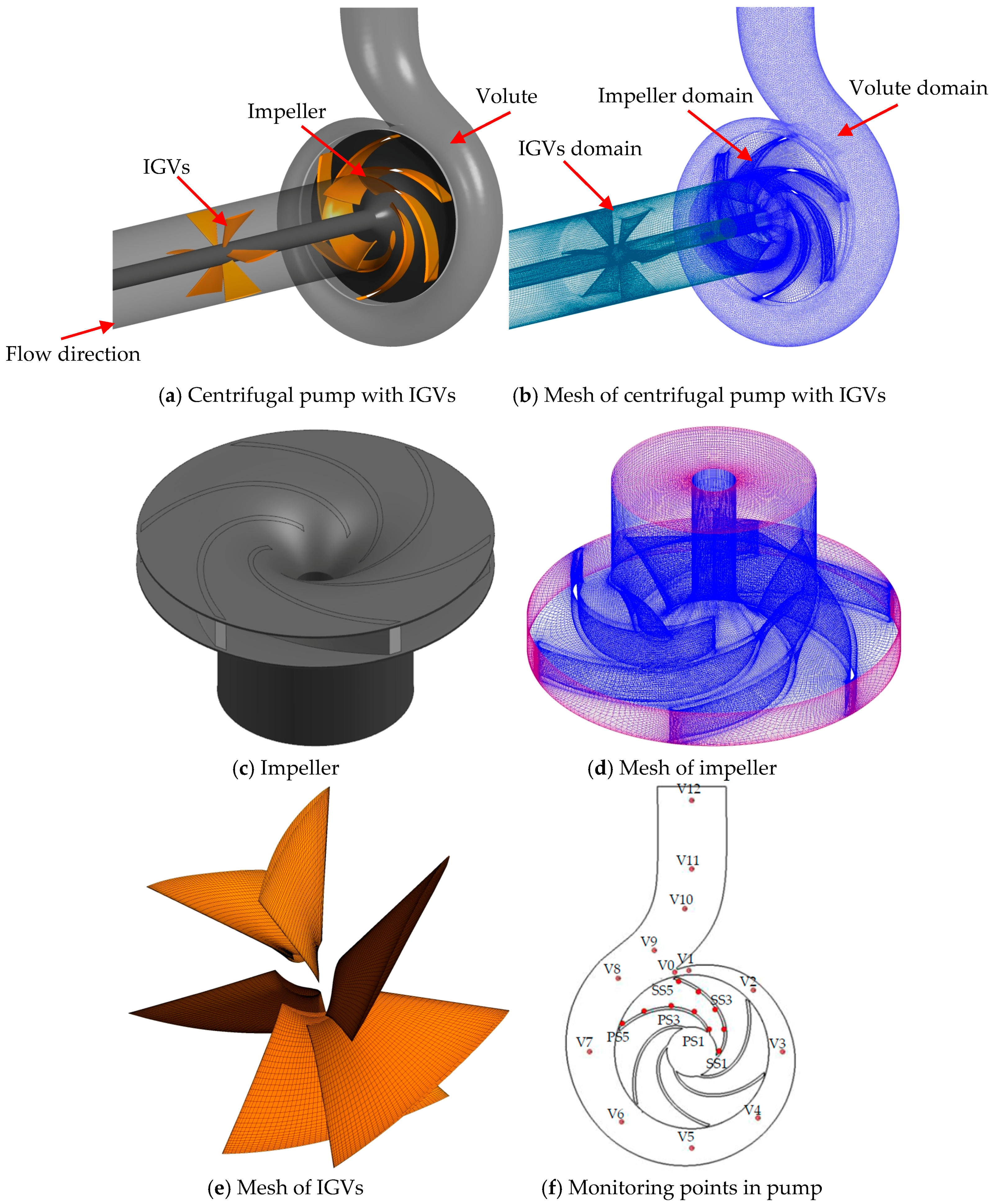
Figure 3.
Time histories of pressure fluctuations on PS4 and V0.
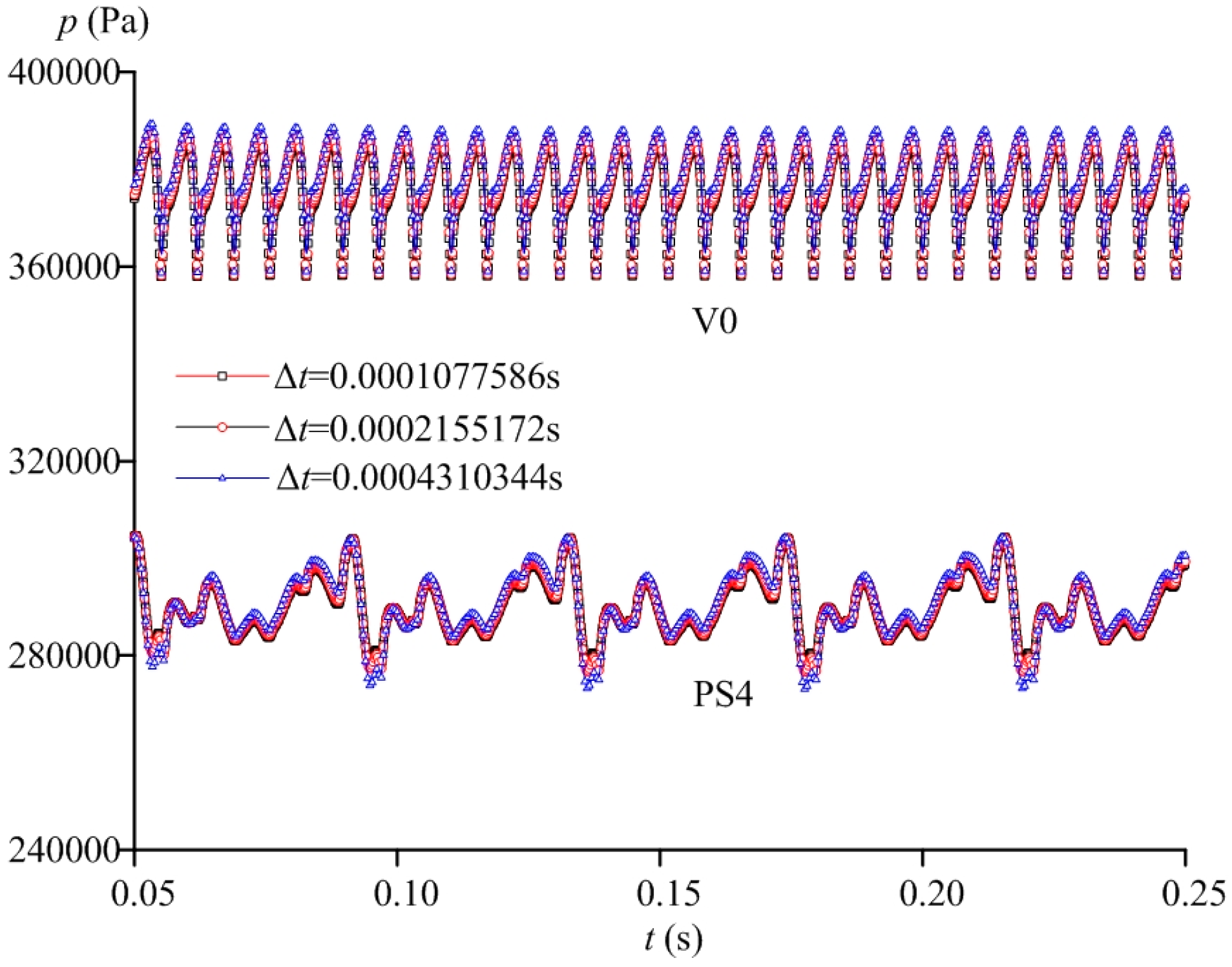
Figure 4.
Comparison of pump performance between the experimental and simulation results.
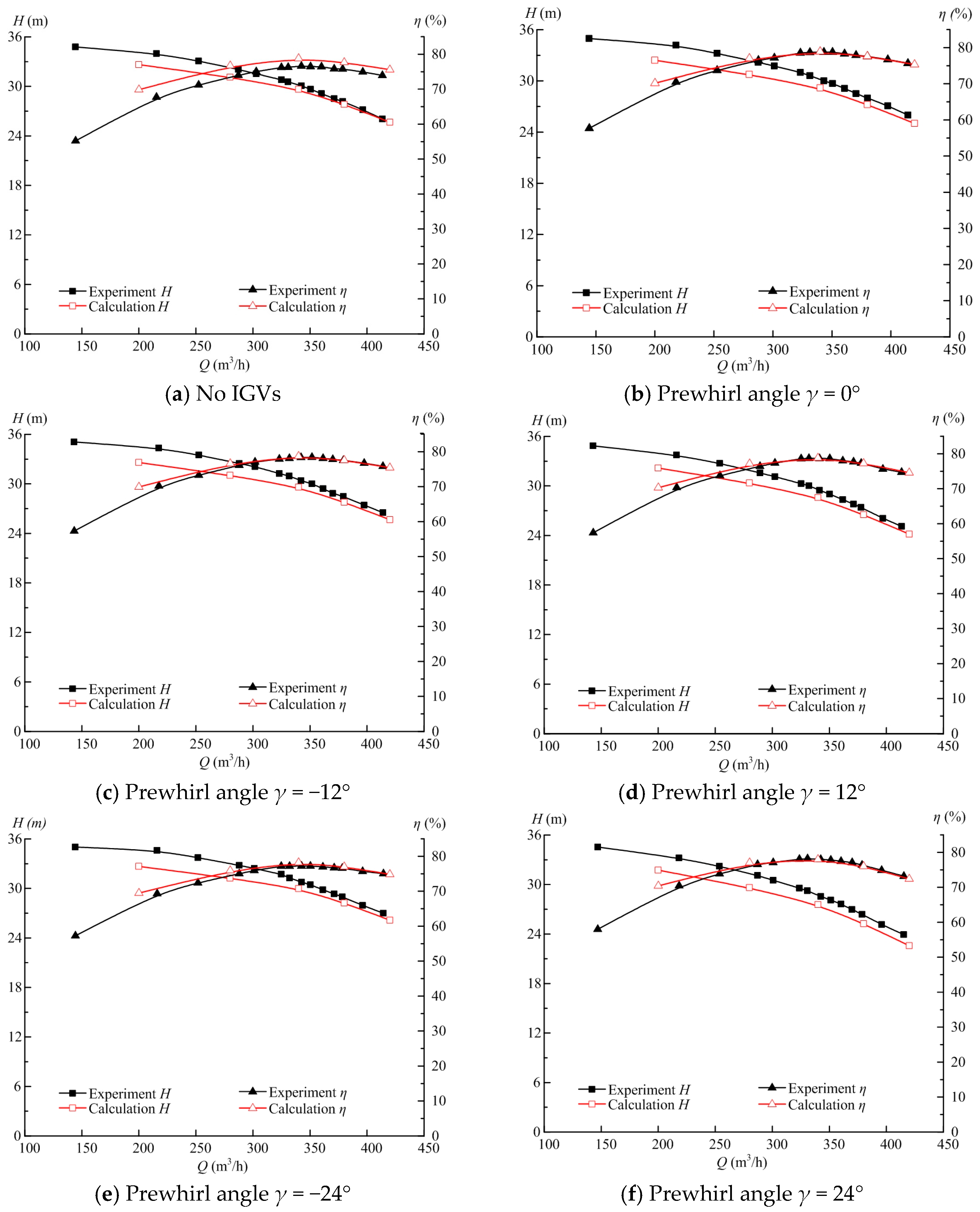
Figure 5.
Experimental results of head and efficiency in pumps without and with IGVs.
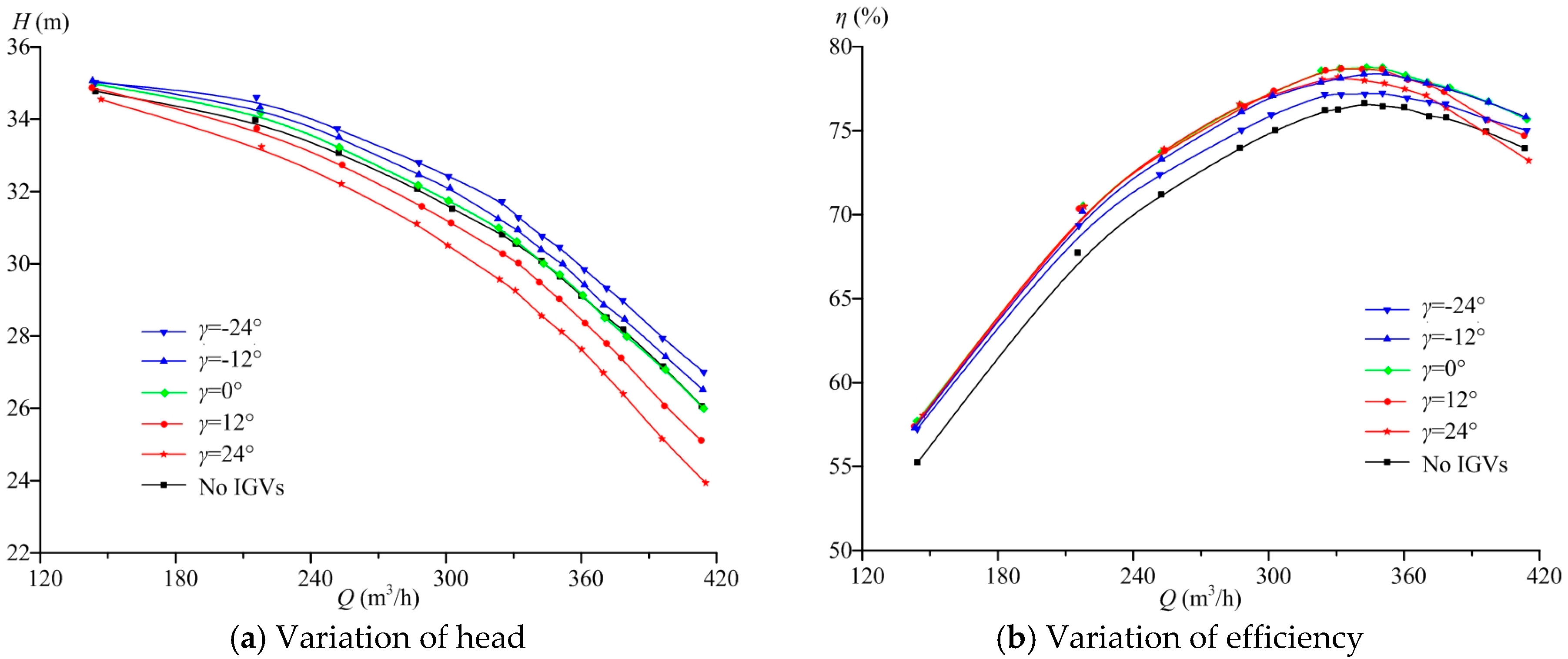
Figure 6.
Pressure distribution and surface streamlines in a blade-to-blade passage at Q = 200 m3/h.
Figure 6.
Pressure distribution and surface streamlines in a blade-to-blade passage at Q = 200 m3/h.
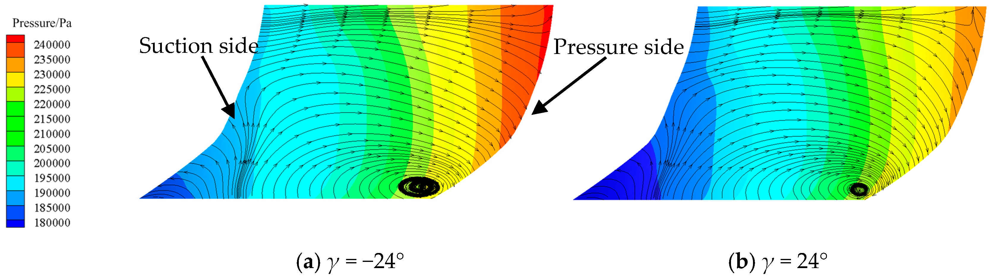
Figure 7.
Isosurface of Q = 1.5 × 10⁵ s−2 in impeller passage for pumps without and with IGVs.

Figure 8.
Isosurface of Q = 1.5 × 10⁵ s−2 in the suction pipe for pumps with IGVs.
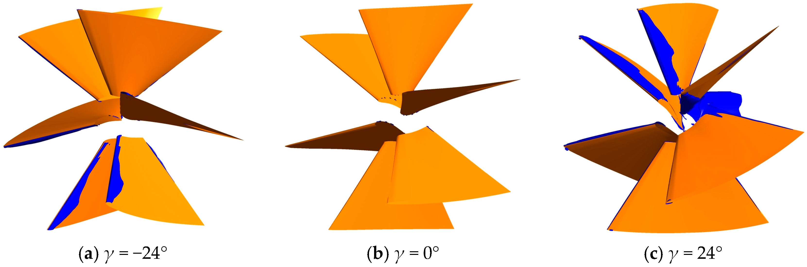
Figure 9.
Pressure gradient and turbulence intensity distribution at the middle span of the impeller.
Figure 9.
Pressure gradient and turbulence intensity distribution at the middle span of the impeller.
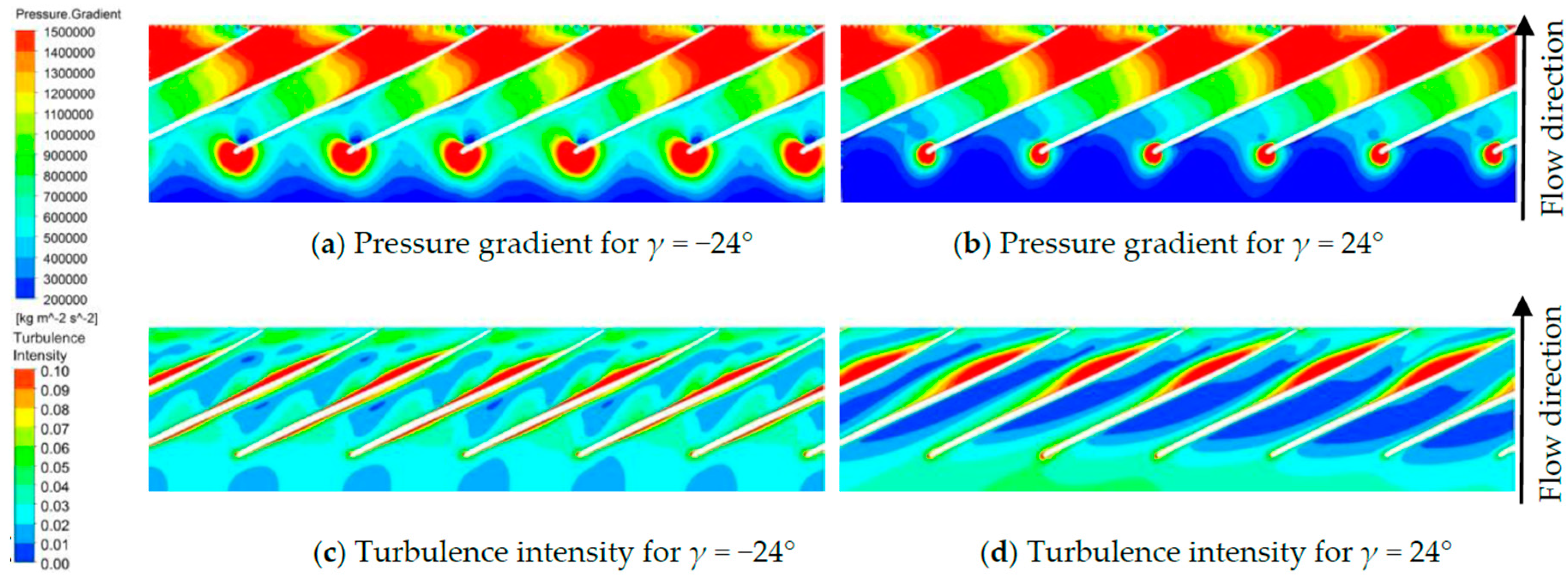
Figure 10.
Circumferential velocity distribution at the impeller inlet with different axial distances (γ = 0°).
Figure 10.
Circumferential velocity distribution at the impeller inlet with different axial distances (γ = 0°).

Table 1.
Parameters for the centrifugal pump.
| Parameter | Value |
|---|---|
| Rated Flow Rate Q (m3/h) | 340 |
| Rated Head H (m) | 30 |
| Rotational Speed n (r/min) | 1450 |
| Specific Speed ns | 127 |
| Number of Impeller Blades Zi | 6 |
| Number of Inlet Guide Vane Blades Zg | 6 |
| Impeller diameter D2 (mm) | 329 |
| Blade width at exit b2 (mm) | 34.6 |
| Diameter of Pump Inlet Di (mm) | 350 |
| Diameter of Pump Outlet Do (mm) | 420 |
Table 2.
Pump head H and efficiency η versus mesh elements.
| Item | Mesh 1 | Mesh 2 | Mesh 3 | Mesh 4 |
|---|---|---|---|---|
| Suction pipe | 290,880 | 290,880 | 290,880 | 290,880 |
| Impeller | 744,840 | 1,190,052 | 1,773,612 | 2,200,800 |
| Volute | 674,234 | 674,234 | 674,234 | 674,234 |
| Whole passage | 1,709,954 | 2,155,166 | 2,738,726 | 3,165,914 |
| H/H1 | 1 | 1.0022 | 1.0048 | 1.0065 |
| η/η1 | 1 | 1.0003 | 1.0006 | 1.0004 |
Table 3.
Experimental results of the highest efficiencies and corresponding flow rates.
| Item | No IGVs | γ = −24° | γ = −12° | γ = −0° | γ = 12° | γ = 24° |
|---|---|---|---|---|---|---|
| Flow rate at highest efficiency (m3/h) | 342.43 | 350.36 | 351.74 | 343.23 | 332.1 | 330.78 |
| Highest efficiency (%) | 76.63 | 77.23 | 78.42 | 78.76 | 78.68 | 78.18 |
Table 4.
Spectrum analysis of pressure fluctuations in pumps without and with IGVs (Q = 340 m3/h).
| Monitoring Point | Dominant Frequency | Maximum Amplitude of Pressure Fluctuation (Pa) | ||||||
|---|---|---|---|---|---|---|---|---|
| No IGVs | γ = 0° | γ = −24° | γ = 24° | No IGVs | γ = 0° | γ = −24° | γ = 24° | |
| PS1 | fi | fi | fi | fi | 4202 | 1381 | 2381 | 1314 |
| PS3 | 2fi | 2fi | 2fi | 2fi | 3938 | 3771 | 3565 | 3774 |
| PS5 | 6fi | 6fi | 6fi | 6fi | 6077 | 6159 | 5976 | 6140 |
| SS1 | fi | fi | fi | 5fi | 3076 | 1079 | 1103 | 337 |
| SS3 | fi | fi | fi | 2fi | 4395 | 1845 | 2878 | 1913 |
| SS5 | 2fi | 2fi | 2fi | 2fi | 4812 | 4707 | 4453 | 4748 |
| V1 | 6fi | 6fi | 6fi | 6fi | 8336 | 8082 | 8491 | 7846 |
| V3 | 6fi | 6fi | 6fi | 6fi | 6580 | 6660 | 6599 | 6685 |
| V5 | 6fi | 6fi | 6fi | 6fi | 2800 | 2784 | 2772 | 2757 |
| V7 | 6fi | 6fi | 6fi | 6fi | 4012 | 3970 | 4020 | 3912 |
| V9 | 6fi | 6fi | 6fi | 6fi | 7868 | 7871 | 7967 | 7768 |
Table 5.
Pressure RMS values in pumps with different prewhirl angles.
| Monitoring Point | No IGVs (Pa) | γ = 0° (Pa) | γ = −24° (Pa) | γ = 24° (Pa) |
|---|---|---|---|---|
| PS1 | 3492 | 1474 | 1979 | 1485 |
| PS3 | 4362 | 4239 | 4309 | 4493 |
| PS5 | 8613 | 8600 | 8492 | 8696 |
| SS1 | 2395 | 839 | 893 | 400 |
| SS3 | 3960 | 2240 | 2674 | 2290 |
| SS5 | 5898 | 5731 | 5709 | 5880 |
| V1 | 9634 | 9610 | 9680 | 9501 |
| V3 | 4791 | 4845 | 4804 | 4861 |
| V5 | 1992 | 1980 | 1972 | 1962 |
| V7 | 2903 | 2873 | 2909 | 2832 |
| V9 | 5817 | 5817 | 5885 | 5743 |
Table 6.
Comparison of pump efficiency with different axial distances.
| Prewhirl Angle | Highest Efficiency in Experiment (%) | Highest Efficiency in Simulation (%) | ||||
|---|---|---|---|---|---|---|
| 280 mm | 380 mm | 460 mm | 280 mm | 380 mm | 460 mm | |
| γ = −24° | 76.900 | 77.230 | 77.630 | 78.183 | 78.191 | 78.210 |
| γ = −12° | 78.280 | 78.420 | 78.440 | 78.714 | 78.719 | 78.720 |
| γ = 0° | 77.880 | 78.760 | 78.560 | 78.871 | 78.894 | 78.877 |
| γ = 12° | 78.410 | 78.680 | 78.400 | 78.784 | 78.774 | 78.765 |
| γ = 24° | 78.250 | 78.180 | 78.190 | 78.022 | 77.988 | 77.946 |
Table 7.
Spectrum analysis of pressure fluctuations in pumps with different axial distances (γ = 0°).
Table 7.
Spectrum analysis of pressure fluctuations in pumps with different axial distances (γ = 0°).
| Monitoring Point | Dominant Frequency | Maximum Amplitude of Pressure Fluctuation (Pa) | ||||
|---|---|---|---|---|---|---|
| 280 mm | 380 mm | 460 mm | 280 mm | 380 mm | 460 mm | |
| PS1 | fi | fi | fi | 1697 | 1381 | 1111 |
| PS3 | 2fi | 2fi | 2fi | 3718 | 3771 | 3778 |
| PS5 | 6fi | 6fi | 6fi | 6137 | 6159 | 6157 |
| SS1 | fi | fi | fi | 1232 | 1080 | 1026 |
| SS3 | fi | fi | 2fi | 2063 | 1845 | 1788 |
| SS5 | 2fi | 2fi | 2fi | 4666 | 4706 | 4704 |
| V1 | 6fi | 6fi | 6fi | 8065 | 8082 | 8080 |
| V3 | 6fi | 6fi | 6fi | 6671 | 6660 | 6653 |
| V5 | 6fi | 6fi | 6fi | 2758 | 2784 | 2785 |
| V7 | 6fi | 6fi | 6fi | 3994 | 3970 | 3947 |
| V9 | 6fi | 6fi | 6fi | 7884 | 7871 | 7852 |
© 2017 by the authors. Licensee MDPI, Basel, Switzerland. This article is an open access article distributed under the terms and conditions of the Creative Commons Attribution (CC BY) license (http://creativecommons.org/licenses/by/4.0/).
Share and Cite
MDPI and ACS Style
Liu, Y.; Tan, L.; Liu, M.; Hao, Y.; Xu, Y. Influence of Prewhirl Angle and Axial Distance on Energy Performance and Pressure Fluctuation for a Centrifugal Pump with Inlet Guide Vanes. Energies 2017, 10, 695. https://doi.org/10.3390/en10050695
AMA Style
Liu Y, Tan L, Liu M, Hao Y, Xu Y. Influence of Prewhirl Angle and Axial Distance on Energy Performance and Pressure Fluctuation for a Centrifugal Pump with Inlet Guide Vanes. Energies. 2017; 10(5):695. https://doi.org/10.3390/en10050695
Chicago/Turabian StyleLiu, Yabin, Lei Tan, Ming Liu, Yue Hao, and Yun Xu. 2017. "Influence of Prewhirl Angle and Axial Distance on Energy Performance and Pressure Fluctuation for a Centrifugal Pump with Inlet Guide Vanes" Energies 10, no. 5: 695. https://doi.org/10.3390/en10050695
Note that from the first issue of 2016, this journal uses article numbers instead of page numbers. See further details here.