1. Introduction
Waste heat at temperatures a couple of dozen degrees above the ambient temperature is a vast energy source. This low-grade thermal energy is mainly discharged from power plants and A/C systems. Because the conversion efficiencies of power plants are typically only about 30%, and the amount of heat discharged from an A/C system is equal to the heat removed from the cooled space plus the heat converted from work input, a tremendous amount of very low-temperature waste heat is produced daily from power and industrial plants, A/C systems, and other processes around the world. This abundant energy source has been used directly for space heating or as the heat source in heat pumping-applications, but has seldom been utilized for (mechanical or electrical) power generation.
According to the Carnot principles [
1], the maximum thermal efficiency for a heat engine operating between thermal energy reservoirs at 20 and 50 °C is only 9%. In addition, a 5 to 10 °C temperature difference is often required for effective heat transfer between the heat engine and its surroundings. The low conversion efficiency (due to a low temperature differential) and low power output (due to low heat transfer rates) have led to little interest in LTD (low-temperature-differential) engine research and the slow development of these kinds of energy converters in the past. The recent concerns about sustainability and environmental awareness have attracted increased interest in wider and more efficient uses of low-temperature waste heat, in particular, the heat discharged from large power plants and A/C systems. If this free energy could be used to generate power, the emission of greenhouse gases and thermal pollutions to the environment would be greatly reduced. The fuel or electricity costs of power plants or A/C systems would also drop.
Of the various thermal-to-mechanical or electrical energy conversion techniques, TE (thermoelectric) generators, TM (thermal-magnetic) motors, and SMA (shape-memory alloy) heat engines have been proven to be feasible for temperature differentials of only a few dozen degrees Celsius. SMA engines received a lot of attention a few decades ago, and a variety of SMA materials and engine designs have been explored to improve the conversion efficiency and power output (e.g., [
2]). The simplest SMA engine consisted of a SMA wire wrapped around two pulleys, with one pulley dipped in a hot water bath and the other cooled by the ambient air. Because the working substances of SMA engines are in the solid phase, and solids have higher thermal inertia (per unit volume) than gases, the changes in substance temperatures and shapes are slower. Heat sources with temperatures 50 °C above the ambient temperature or higher and slender-structural SMA materials are often needed for fast shape changes.
The TE generator is probably the most popular choice by far for direct thermal-to-electric energy conversion at very low temperature differentials. Currently, TE devices have been developed to generate a small amount of electricity from body heat, which is only a couple dozen degrees above the ambient temperature. The generated electricity was used to power watches, handheld flashlights, and other small electronic devices. The hot and cold ends of a TE device is typically only a few millimeters apart, and TE materials have high thermal conductivities. As a result, heat transfer in a TE generator is much more effective than heat transfer in a heat engine that utilizes a gas as the working fluid. The high heat transfer rate in a TE generator translates into high power output, but its conversion efficiency is low due to heat leakage between the closely separated hot and cold ends of TE energy converters [
3]. If conversion efficiency is more important than power output, heat engines that operate on the Stirling cycle or its variations are more promising to approach the maximum possible efficiency predicated by the second law of Thermodynamics [
1]. Theoretically, the conversion efficiency from mechanical energy to electricity can be 100% [
4].
The Stirling cycle has the same efficiency as the Carnot cycle when operating between the same temperature limits. Unlike the Carnot heat engine, a regenerator is required in the Stirling engine to store the heat removed from the working fluid during the constant-volume heat removal process. The stored thermal energy is later released to pre-heat the working fluid before heat input from an external heat source takes place. A complicated mechanism is also needed to keep the volume of the working fluid constant when flowing through the regenerator.
Since the first engine operating on the Stirling cycle was invented by Robert Stirling in 1816 [
5], various designs of the Stirling engine have been tested to improve the engine efficiency and reliability [
6]. Researchers at the Philips Research Laboratory (Cambridge, MA, USA) integrated an electric generator and a Stirling engine around 1937 to produce electricity [
7]. A one-dimensional dynamic model was developed by Ulloa et al. [
8] to simulate the steady-state and transient operations of a Stirling-engine based CHP (combined heating and power) system. The model requires only few configuration parameters and is therefore adaptable to a wide range of commercial Stirling engines. Stirling engines have also been used in recent years to produce electrical power in micro-CHP systems [
9].
A solar-powered Stirling engine was designed and tested by White in 1983 [
10]. By pressurizing the displacer chamber, White was able to raise the Stirling engine’s efficiency to about 30%. The GA (genetic algorithm) scheme was employed in Chen et al.’s study of a solar-powered Stirling engine to maximize the engine power output [
11]. According to their optimization analysis, the power output of a Stirling engine with an efficiency of 0.363 was at a maximum when heated by 4000 W/m
2 solar flux if the collector temperature was maintained around 560 K. A thermal model was developed by Gil et al. [
12] for a dish Stirling cavity. The cavity absorbed thermal radiation from a solar concentrator and transferred the absorbed energy to the working fluid of a Stirling engine to produce power. It was found in Gil et al.’s investigation that smaller aperture radii and higher receiver absorptivities made the cavity more efficient. The optimal cavity height depended on the aperture ratio. For a 28 kWt (Kilowatt thermal) dish Stirling with an aperture radius of 12 cm, the optimal aperture height of the cavity was about 20 cm.
In recent years, LTD heat engines have drawn the attention and interest of many researchers and engineers with an aim to compete with other LTD power generators such as SMA heat engines and TE generators [
13]. Haneman et al. [
14,
15] studied the feasibility of LTD Stirling engines for ambient energy scavenging. Kolin constructed an engine [
6] that could run at a temperature differential of 15 °C. Senft modified the LTD engine originally developed by Ossian Ringbom in 1905 [
6], which did not have any mechanical linkage to drive the displacer. The modified heat engine could run at a temperature differential of only 6 °C. Senft and Kolin [
6] had worked closely to develop new LTD heat engines that could harness very low-temperature waste heat and promote fuel diversity.
Iwamoto et al. [
16] compared the performances of prototype LTD and HTD (high-temperature-differential) Stirling engines by measuring their heat losses and power outputs. The HTD Stirling engine was powered by hot flue gases from combustion reactions. Their experiments reassured the potential of the LTD engine in utilizing different types of heat sources as previously demonstrated by Senft and Kolin, even though the LTD engine was less efficient than the HTD engine. Kongtragool and Wongwises [
17] developed a mathematical model to determine the optimum absorber temperature for a solar-powered LTD Stirling engine under two limiting conditions: maximum possible engine efficiency and maximum possible power output. They found that the results were not significantly different, and the maximum overall efficiency subject to the latter (maximum possible power output) could reach 55% Carnot cycle efficiency.
At present, many LTD heat engines capable of utilizing low-grade thermal energy are commercially available. Alveno et al. [
18] tested three commercial LTD engines of similar design and comparable size, and found the one with concentric power and displacer cylinders (a configuration similar to the Beta-type Stirling engine) could run on the smallest temperature difference, but the American Stirling Company (San Diego, CA, USA) MM-7 engine, which had the largest heat transfer surface area, produced the highest power output. The MM-7 engine, which is similar to the Gamma-type Stirling engine, was selected in the present theoretical investigation of LTD engines. This engine was also selected by Aragon-Gonzalez et al. in their experimental study of low-cost LTD engines [
19].
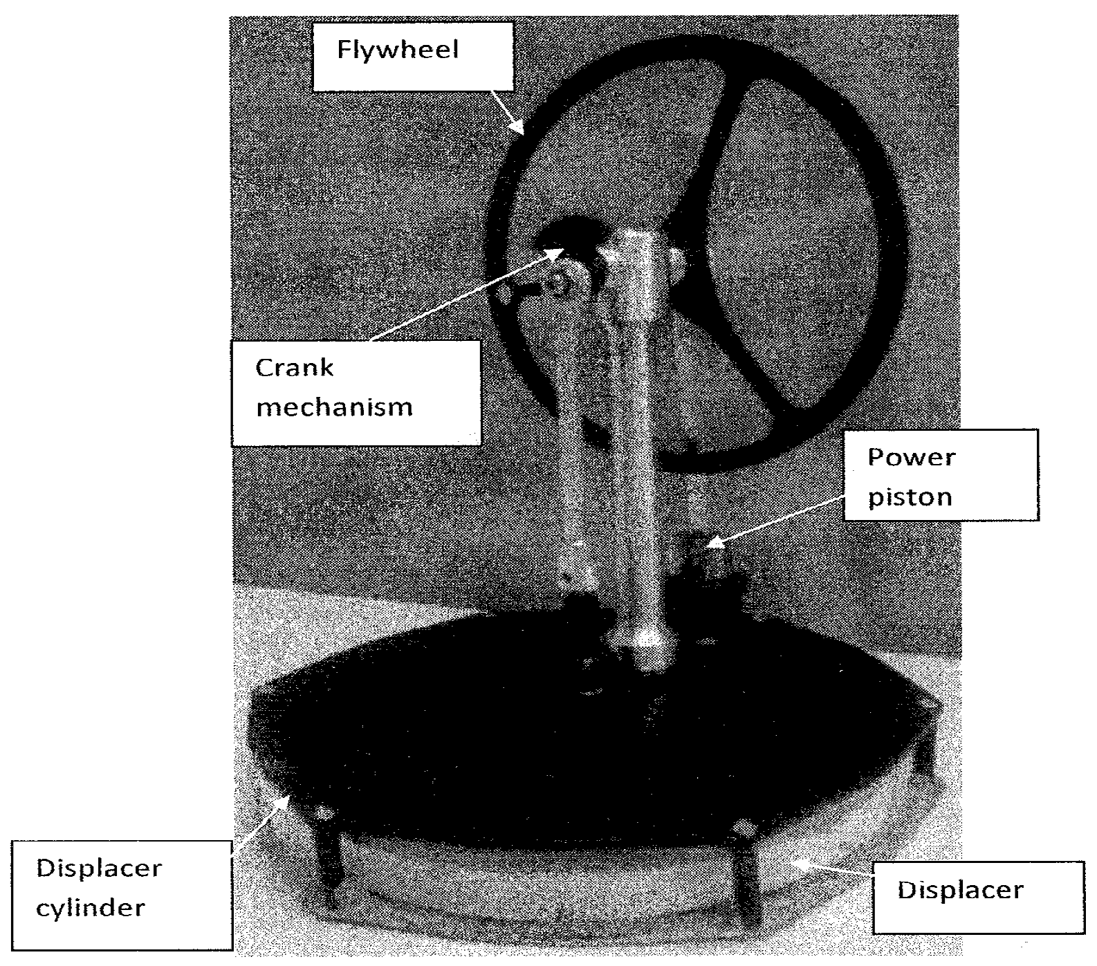
As can be seen in
Figure 1, the MM-7 engine uses a very simple crank mechanism to reduce the cost and the construction and operation complexities. It also lacks an effective regenerator for internal heat exchange between the working fluids at high and low pressures. These changes in engine design have made the MM-7 engine different from the “standard” Stirling engine in two major ways. First, the regeneration process of the MM-7 engine does not take place at constant volume. Second, the working fluid is not at the heat source or sink temperature when entering the hot or cold end of the displacer cylinder. Therefore, the conversion efficiencies of the MM-7 engine and other LTD engines of similar design are lower than that of the Carnot or Stirling engine, even under the ideal operating conditions in which all frictional losses are eliminated and all heat transfer processes occur across an infinitesimally small temperature difference.
Simplified thermodynamic analyses of the Stirling engine can be found in Senft’s book [
6]. Presented in this paper is a combined thermal-flow analysis of the MM-7 engine in which the frictional losses of the working fluid were calculated for different engine speeds and temperature differentials. Temperature correction factors were introduced to assess the departure from the ideal heat transfer processes. The analysis performed in this paper is a 2nd-order modeling as it includes the factors such as the pressure drop across the displacer, fluid friction, and non-ideal heat transfer that are ignored in the 1st-order model [
6]. While the MM-7 engine has been investigated before and its power outputs have been measured in [
18,
19] for different temperature differentials and engine speeds, the decrease in power output when the engine speed increased beyond a certain value could not be explained by the 1st-order model. According to the 1st-order model, the engine output should increase linearly with the engine speed. This shortcoming motivated the present 2nd-order analysis of the MM-7 engine. The objective of the combined thermal-flow analysis in this paper is to study the drop in engine power output at high engine speeds due to viscous friction, ineffective heat transfer, and the pressure difference across the displacer.
According to our analytical analysis, the powers required to overcome the viscous friction of the working fluid and the pressure difference across the displacer were found to be much smaller than the power produced by the power piston for engine speeds below 10 RPS (revolutions per second). Compared with the power outputs measured in the experiments [
18,
19], the difference between the working fluid temperature and the heat source or sink temperature during heat addition or rejection was very large for the MM-7 engine at speeds higher than 1 RPS. Therefore, heat-transfer devices and/or techniques to enhance convective heat transfer inside the displacer cylinder are strongly recommended. This recommendation is also applicable to other LTD engines of similar design and comparable size.
3. Thermal-Flow Analysis of the MM-7 Engine
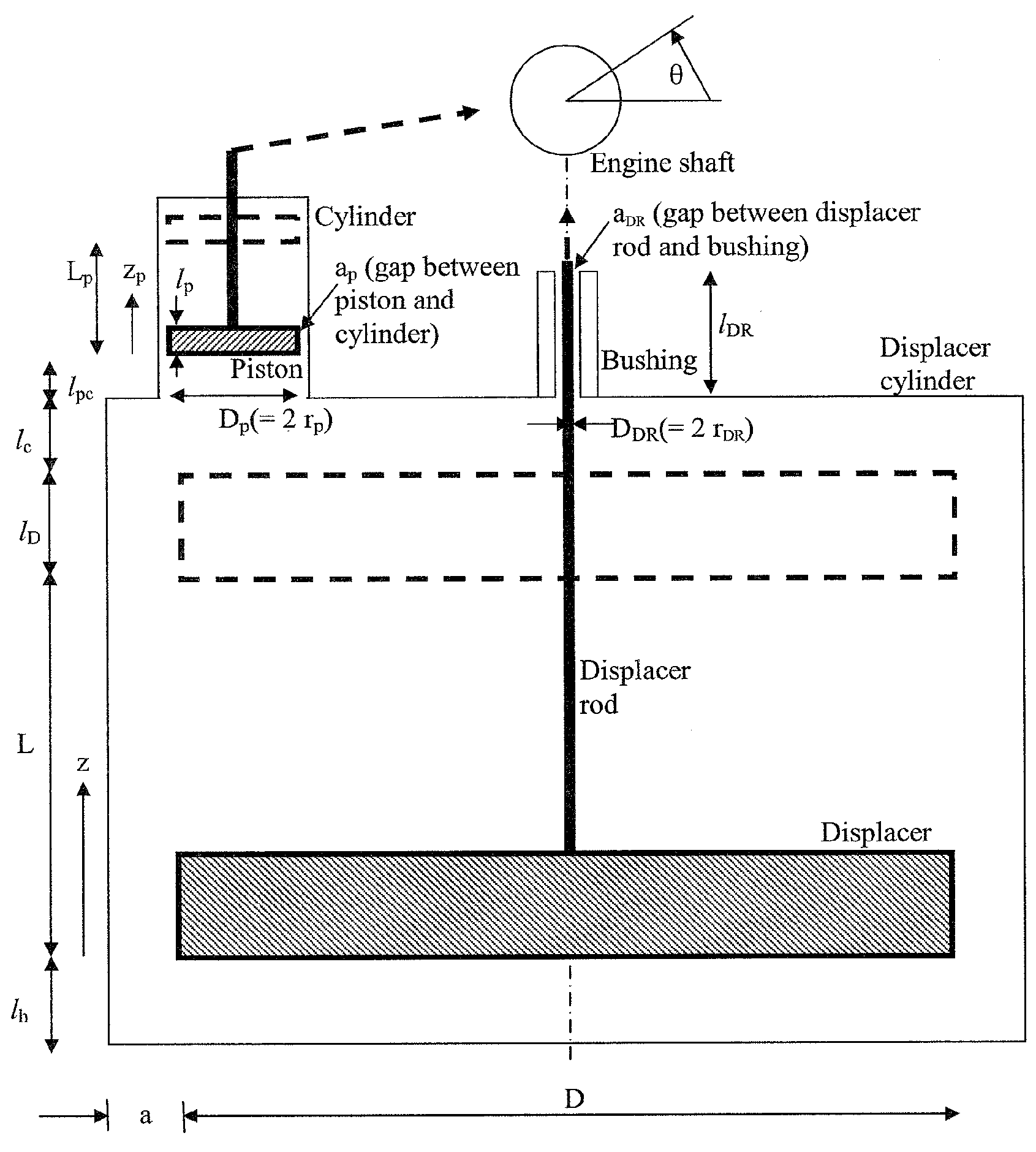
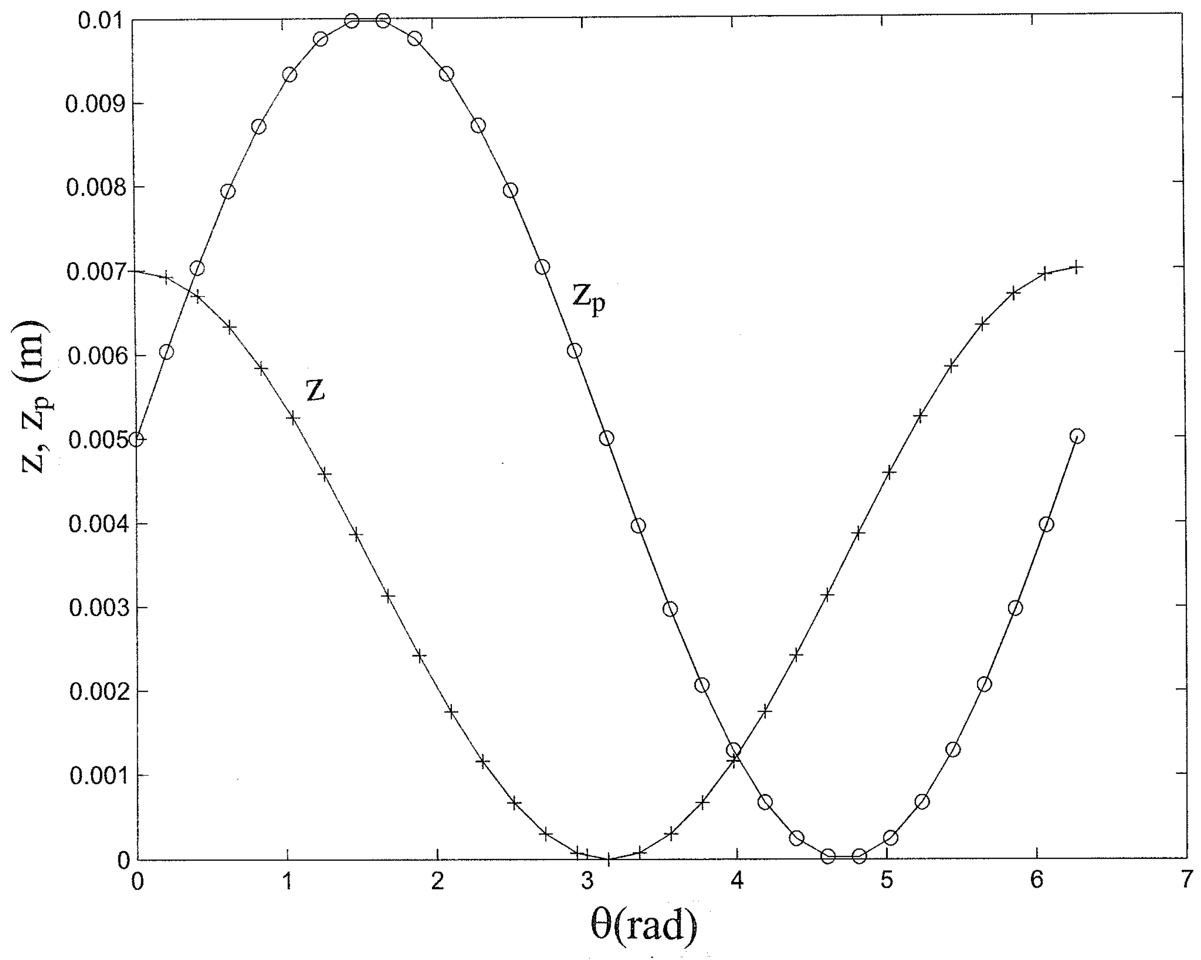
A simple cranking mechanism is employed in the MM-7 engine to convert the linear movements of the power piston and the displacer to rotational movements. The linear movements are both sinusoidal and have the same frequency, but the strokes are different, and there is a phase lag between the piston and displacer movements. Referring to the drawing in
Figure 2, the relationships between the linear movements of the piston and the displacer and the angular displacement of the engine shaft are:
where
z and
zp are the vertical positions of the displacer and the piston, and
α is the phase difference between the movements of the piston and the displacer. The displacer is in its highest position (
z =
L) at
θ = 0. Plotted in
Figure 3 are the vertical positions of the piston and the displacer as functions of the crank angle for
α = −90°. This is the phase angle that yields the highest theoretical engine power output. For a constant engine speed, the time variable (
t, in seconds) is equal to the abscissa of the plot in
Figure 3 divided by 2
π and by the engine speed (in RPS). The vertical velocities of the displacer and the piston are the time derivatives of their positions:
It should be pointed out that some Stirling engines use a sophisticated crank mechanism to enhance the engine power output. The linear movements of these engines may not be sinusoidal functions of the crank angle.
As depicted in
Figure 4, the volume of air in the cold region of the engine is the sum of the air volume in the power cylinder (=
Vp +
Vpd) and the air volume above the displacer in the displacer cylinder (=
Vcd +
VcD). The volume of air in the hot region of the engine is the volume below the displacer (=
VhD +
Vhd).
Vp in
Figure 4 is the volume swept by the piston.
Vpd is the clearance of the power cylinder.
Vcd and
Vhd are the upper and lower clearances of the displacer cylinder.
VcD and
VhD are the volumes swept by the displacer above and below the displacer. The swept volumes can be expressed as functions of the shaft angle, the piston or displacer radius, and the strokes:
Because of the small size and low speeds of the MM-7 engine, it is reasonable to assume that the airflow in the engine is laminar. At 10 RPS, the maximum Reynolds number based on the mean velocity and the hydraulic diameter for the flow through the annulus between the displacer and the displacer cylinder is 985. The maximum Reynolds numbers for the flows through the annuli between the piston and the cylinder and between the displacer rod and the bushing are less than unity. Since the critical Reynolds number for internal flows is about 2300, the flow in the annulus between the displacer and the displacer cylinder may become turbulent when the engine speed exceeds 23 RPS, or for engines more than twice the size of the MM-7 engine at 10 RPS.
The rate of airflow from the cold to the hot region of the engine depends on the pressure difference across the displacer and the viscous force on the lateral surface of the displacer. The flow through the annulus of the displacer is simplified to the Couette–Poiseuille flow as a first approximation. This is a typical approximation for flow through the annulus of a piston-cylinder device (e.g., [
20,
21]. The flow rate in Equation (8) is identical to that in Equation (13) in Mantri et al.’s friction model for a reciprocating compressor [
20]). Based on this approximation, the volume flow rate is calculated from the following equation:
Using the above equation, the pressure gradient in the displacer annulus can be related to the engine shaft angle and speed as follows:
where
If the pressure gradient in the displacer annulus is approximated as:
The pressure in the hot region of the engine can be related to
pc, the pressure in the cold region of the engine, as:
The total amount of air in the engine is equal to the sum of air masses in different regions in the engine:
The temperatures of the air above and below the displacer are not uniform and depend strongly on the flow conditions. In the present thermodynamic analysis of the MM-7 engine, the following average temperatures are used for air above and below the displacer:
The temperature correction factors (Cc and Ch) defined in Equations (14) and (15) allow the average air temperatures in the hot and cold regions of the displacer cylinder to vary between their minimum and maximum possible values. At very low engine speeds, there is sufficient time for effective heat transfer inside the displacer cylinder, and the average air temperatures in the hot and cold regions of the displacer cylinder approach the hot and cold end temperatures of the engine (Th and Tc). In this case, the temperature correction factors are close to zero. At high engine speeds, there is little time for effective heat transfer inside the displacer cylinder. Consequently, the average air temperatures in the hot and cold regions of the displacer cylinder remain nearly unchanged and are very close to the average of the hot and cold end temperatures of the engine. In this case, Cc and Ch are both close to unity.
Using the ideal-gas equation of state, the mass of air in the cold region of the engine is:
where
The mass of air in the hot region of the engine is:
where
Assuming the air pressure and temperature in the displacer annulus are the averages of the pressures and temperatures in the regions above and below the displacer, the mass of air in the annulus can be computed from:
where
Neglecting the small amount of air leaked through the gap between the displacer rod and its bushing and the gap between the piston and the power cylinder, the total amount of air in the engine remains constant during operation, and air pressure in the cold region of the engine can be expressed as a function of
M,
θ and
ω:
The moving-boundary work produced by the piston per cycle can be computed from the following integration:
The volumes of air in the gap of the long bushing of the displacer rod, and in the annulus between the piston and the power cylinder, are neglected in the above air volume calculations. These volumes are very small. Airflows through these two narrow flow channels are also neglected in the present thermodynamic analysis. The piston was replaced by a flexible membrane in an earlier version of this commercial LTD engine to eliminate air leakage in the power cylinder. Such a change probably caused too much resistance to the engine movement and was later abandoned in favor of the air bearing design of the MM-7 engine.
The amount of air leaked to the surroundings when the engine pressure is higher than the surrounding air pressure is equal to the amount of air leaked into the engine when the engine pressure is lower than the ambient pressure. Thus, the surrounding work done on or by the leaked air cancel each other out in a complete cycle. In a similar argument, the surrounding work when the piston moves upward is equal (but opposite in sign) to that when the piston moves downward. The net useful work output of the engine per cycle is therefore the moving-boundary work of the air underneath the piston minus the work required to overcome the viscous frictions on the lateral surfaces of the piston, the displacer, and the displacer rod, and the work required to overcome the pressure difference across the displacer.
Using the analytical solutions for steady, fully developed, incompressible laminar flow between two parallel plates or in an annulus, the shear stresses on the lateral surfaces of the displacer, the piston, and the displacer rod are:
The shear stresses due to pressure differences are neglected in Equations (31) and (32), since these two flow channels are very long and narrow. The flows can be approximated by the Couette flow. The corresponding shear forces and work required to overcome the viscous drags per cycle are:
The work required to overcome the pressure difference across the displacer per cycle can be calculated from:
The net work per cycle multiplied by the engine speed (in RPS) gives the engine power output (in Watts).
Air pressure in the cold region of the engine is expected to be pretty uniform at any instance for low engine speeds. As a result, the boundary work produced by the piston can be determined by measuring the time variation of air pressure in the cold region of the engine and the piston displacement.
The mechanical power outputs of the MM-7 engine had been measured in Aragon-Gonzalez et al.’s paper [
19] and in Alveno et al.’s experiments [
18] for different engine speeds and temperature differentials. A dynamometer was employed in Aragon-Gonzalez et al.’s experiments to measure the engine’s mechanical power. Alveno et al. measured the rate of change in height of a mass lifted by the engine to determine the engine power output. The engine powers measured in these two publications are in good agreement, especially at low engine speeds. For instance, at
ω around 2
π rad/s (=1 RPS) and Δ
T = 20 °C, the measured mechanical power output was about 2 mW in Aragon-Gonzalez et al.’s paper, and about 1.7 mW in Alveno et al.’s report. A few prototype electric generators have also been tested by Alveno et al. to convert the shaft work of the MM-7 engine to electricity. The conversion efficiency was found to be low due to the low torques of the MM-7 engine at low temperature differentials. More research on engine-generator matching is needed for electricity production using the MM-7 engine.
4. Results and Discussions
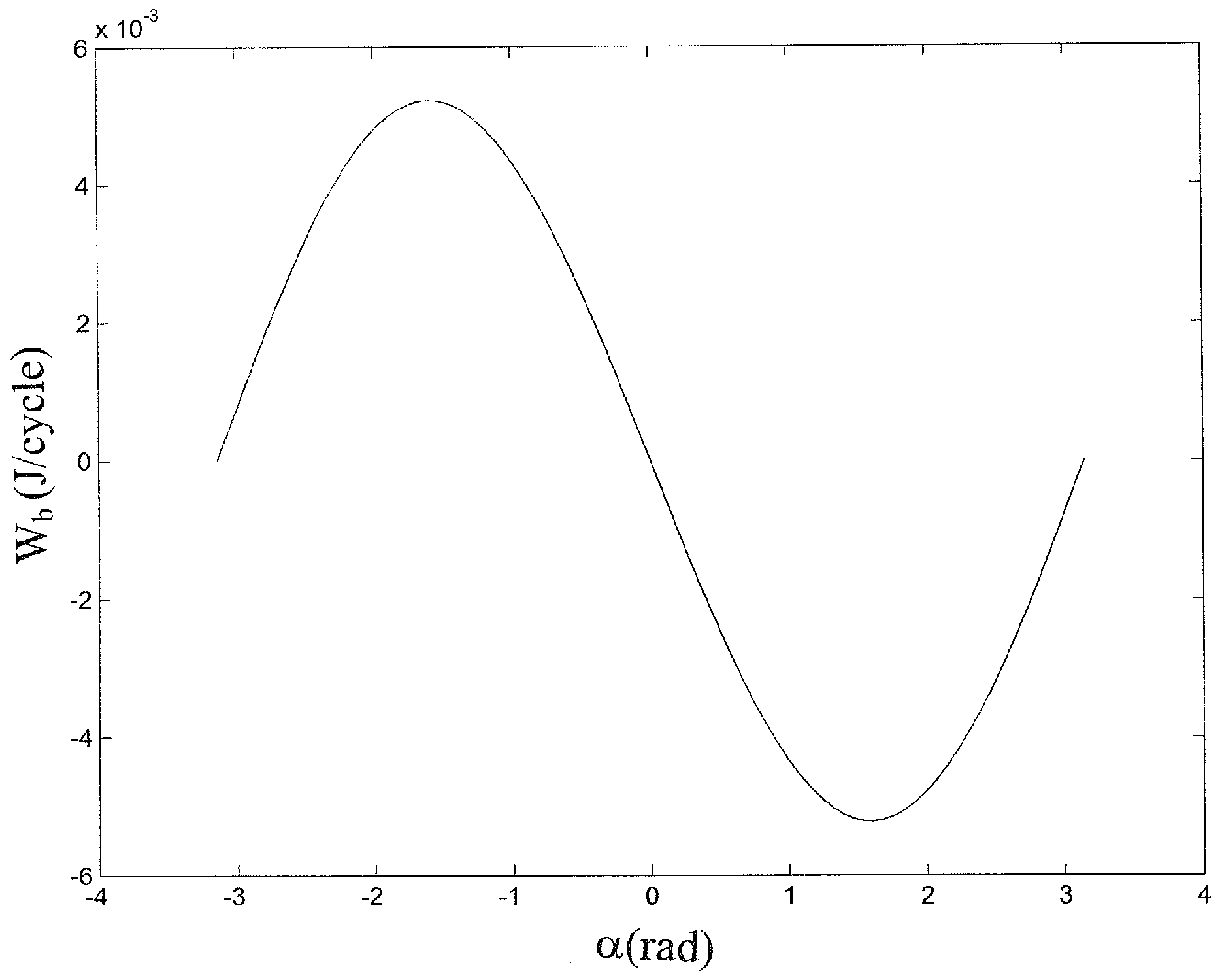
The phase difference between the piston and displacer movements has a significant impact on the engine power output. In theory, the cyclic power output is positive (i.e., a power cycle) when heat is added to the cycle during compression and removed from the cycle during expansion of the working fluid. As shown in the boundary work plot in
Figure 5, the work output of the piston (
Wb) is positive for
α = −
π to 0, and negative for
α = 0 to
π. The boundary work of the piston reached its maximum value at
α = −
π/2. The other forms of work (
Ws,
Wsp,
WsDR, and
Wpd) are almost independent of
α and much smaller than
Wb. Therefore, the net work output of the engine is maximum when
α is around −
π/2. The results and discussions in the remainder of this section are for this optimal phase angle.
The pressure in the engine is at the ambient pressure before the engine starts running. The crank angle at which pc is equal to the ambient pressure (po) was found to affect Wb only slightly, with Wb at its maximum value for θo (the crank angle at which pc = po) = π/2.
The computed air pressure variation in the cold region of the engine and the difference between
pc and
ph are presented in
Figure 6 for
ω = 1 to 10 RPS, Δ
T = 20 °C, and no temperature corrections (
Cc =
Ch = 0). The pressure difference across the displacer increases with engine speed, but
pc is almost independent of
ω for engine speeds below 10 RPS. According to the ideal-gas law, the air pressure increases with temperature, but decreases with volume for a fixed mass. It is interesting to note that the maximum
pc does not occur at
θ = 0, at which the volume of high-temperature air (
VhD +
Vhd) is maximum, nor at
θ = −
π/2 at which the total volume of air (= sum of all the volumes highlighted by the dotted lines in
Figure 4) in the engine is at a minimum. The maximum
pc occurs at an angle between
θ = −
π/2 and 0 at which most of the displacer cylinder is filled with high-temperature air while the total volume of air in the engine is slightly greater than its minimum value.
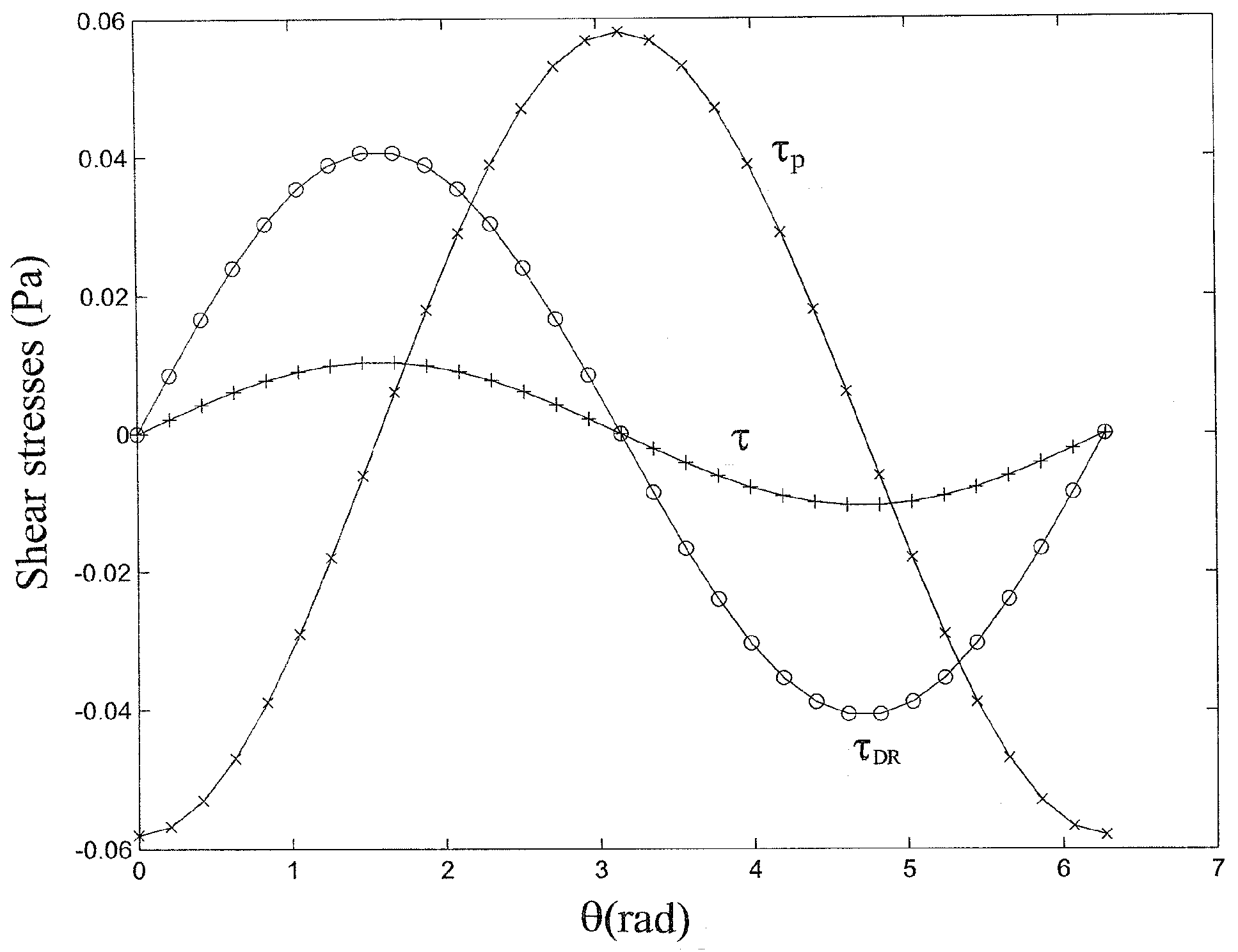
The calculated shear stresses on the lateral surfaces of the piston, the displacer, and the displacer rod are presented in
Figure 7 for
ω = 1 RPS, Δ
T = 20 °C, and
Cc =
Ch = 0. Because of the sinusoidal movements of the piston and the displacer, and the 90° phase difference between the two movements, the shear stresses on the piston and the displacer are sinusoidal functions of
θ and are 90° out of phase. Although
τp is the highest and
τ is the lowest shear stress in this plot, the displacer has the largest lateral surface area. Therefore, the work required to overcome the viscous drag on the displacer is greater than the viscous work on the piston.
Shown in
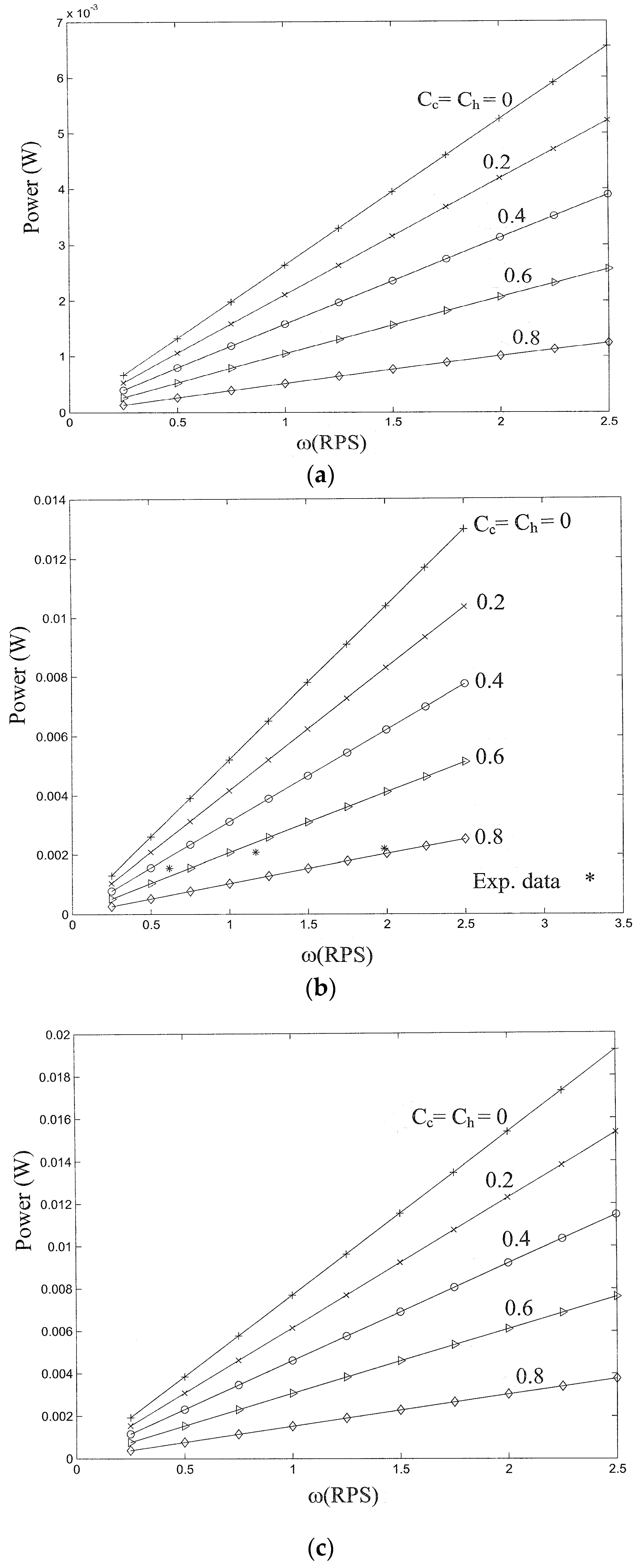
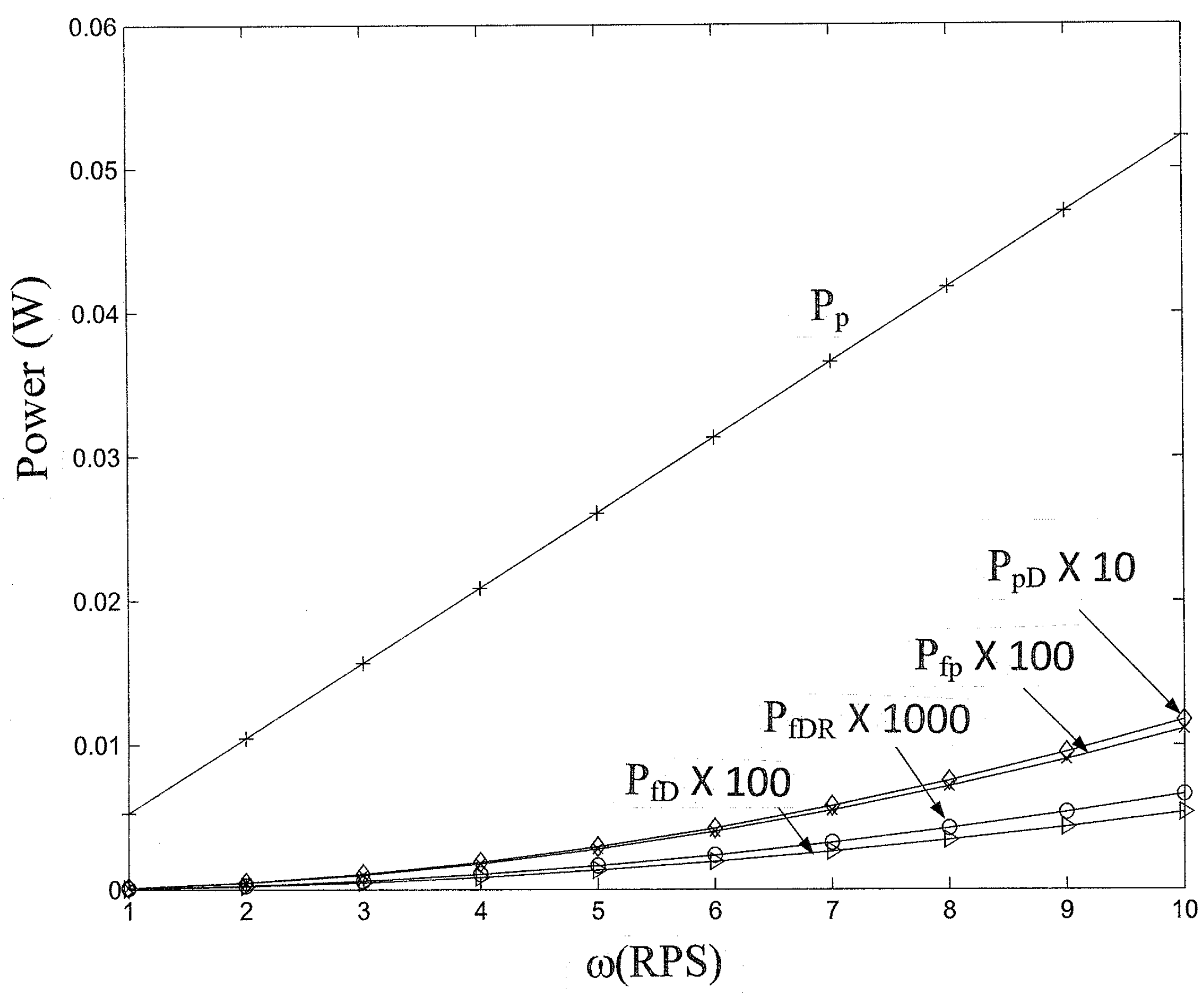
Figure 8a–c are the net power outputs of the engine for different engine speeds and temperature differentials. Different forms of work per unit time are presented in
Figure 9 for Δ
T = 20 °C and
Cc =
Ch = 0. The temperature correction factors
Cc and
Ch were assumed to be independent of engine speed in these calculations. As a result, the boundary work produced by the piston per unit time is almost a linear function of
ω. It should be pointed out that, as the engine speed increases, there will be less time for effective heat transfer between the working fluid and the hot or cold end of the engine, and the temperature correction factors should increase. A comparison of the three plots in
Figure 8 indicates that the relationship between engine power output, and temperature differential at a given engine speed is also almost linear.
The power outputs of the MM-7 engine were measured in [
19] for ∆
T ranging from 16 to 22 °C. Alveno et al.’s experimental data [
18] cover a wider range of temperature differentials. However, a pulley was used in their experiments, and the measured engine power outputs were lower than Aragon-Gonzalez et al.’s measurements due to the friction of the pulley. Because Aragon-Gonzalez et al.’s measurements are more accurate, and their data exhibited a similar trend for ∆
T = 16 to 22 °C, only the data for ∆
T = 20 °C in [
19] were compared with the analytical solution in
Figure 8.
As can be seen in
Figure 9, for
ω < 10 RPS and Δ
T in the neighborhood of 20 °C, the work required to overcome the viscous frictions on the piston and the displacer is much smaller than the boundary work produced by the piston. Even at
ω = 10 RPS, the work required to overcome the pressure difference across the displacer is one-to-two orders of magnitude smaller than the work produced by the piston. Thus, the degradation from the ideal engine performance is primarily due to the ineffective heat transfer during heat addition and rejection. The experimental data (*) in
Figure 8b indicate that the departure from the ideal Ringbom Stirling engine performance (
Cc =
Ch = 0) increases as the engine speed increases. This is due to the insufficient time for effective heat transfer inside the displacer cylinder at high engine speeds. The temperature correction factors are about 0.5 for
ω < 1 RPS, but increase to more than 0.8 at
ω > 3RPS, meaning the change in the working fluid temperature when heat was transferred to or from the cold or hot end of the engine was less than 20% of the maximum possible temperature change for
ω > 3 RPS. This result clearly indicates that heat transfer from the engine hot or cold end to the air in the MM-7 engine is very ineffective at high engine speeds. Fins and/or other heat transfer-enhancing devices should be installed inside the displacer cylinder to improve heat transfer during heat addition and rejection.
If the frictional losses and the pressure difference across the displacer are neglected and the air temperatures in the hot and cold regions of the displacer cylinder are identical to the heat source and sink temperatures, the cycle we studied becomes the ideal Ringbom Stirling engine cycle. Since the frictional losses and the pressure difference across the displacer were found to be very small for the MM-7 engine at speeds below 10 RPS, the results of zero temperature corrections (Cc = Ch = 0) and the ideal Ringbom Stirling cycle results are pretty much the same if Th and Tc are replaced by the heat source and sink temperatures.
To the best of our knowledge, the analytical solution we derived is the first quantitative analysis of this type of LTD engines with viscous friction, boundary work on the displacer, and non-ideal heat transfer all taken into account. The comparison with experimental results in
Figure 8b validated that our analytic solution is “in the ballpark” of the measured engine performance at low engine speeds. The mathematical model and analytical solution developed in the present investigation of the MM-7 engine can be easily modified and applied to other LTD heat engines of similar design and operating conditions. Because the flows through the annuli were assumed to be laminar in our analysis, the engine speed should be limited to about 23 RPS for engines with sizes comparable to the MM-7 engine. The speed limit for the laminar flow assumption to be valid decreases as the engine size increases. The departure from the ideal heat transfer processes increases with engine size. This is because the heat transfer areas increase as the square of the engine size, whereas the air volume in the engine increases as the cube. As the engine size increases, the average air temperatures in the hot and cold regions of the displacer cylinder deviate more from the engine hot and cold end temperatures at a given engine speed.

