1. Introduction
Wireless power transfer (WPT) technology is capable of charging electronic devices wirelessly eliminating the traditional cable requirement. This technology is not only more convenient, but can also enhance the health and safety within both domestic and commercial environments. Although WPT can be realized using either inductive coupling or radio frequency (RF) signals (see e.g., [
1,
2,
3]), the former will be the focus of this paper.
Recently, a great number of attempts have been made towards the deployment of inductive WPT systems, since low energy density batteries are no longer sufficient to saturate the escalating energy demand of the electronic apparatus [
3,
4]. The need for an industry standard for the interoperability of the wireless devices was elevated simultaneously with the increasing number of wireless charging efforts. As a result, the Qi standard was introduced by the wireless power consortium and was adopted for both low and medium wireless power charging specifications during the last few years [
5,
6,
7]. This standard is based on a tightly coupled two-coil system supporting charging up to 5 W. However, the efficiency of the two-coil system fluctuates upon the coil alignment and the distance between the transmitting coil (Tx) and receiving coil (Rx) [
8,
9]. The two-coil charging system has also been proposed for numerous appliances, especially for electric vehicle (EV) charging applications [
10,
11].
In order to maximize the distance between the Tx and Rx, the strongly-coupled magnetic resonance (SCMR) method was introduced in 2007 [
12]. The Authors of this study pointed out that this method is capable of wirelessly transferring 60 W of electrical power over a distance of 2 m with 40% efficiency. Moreover, the SCMR system has demonstrated higher efficiencies by designing the transmitting and receiving resonant loops to resonate at the same frequency, where they exhibit the maximum quality factor [
13]. However, the fact that the SCMR system has a high sensitivity to the misalignment between the coils [
14,
15] and its bulky structure are two main drawbacks of this system. In order to overcome these drawbacks, the conformal SCMR (CSCMR) concept was introduced in [
16]. In this method, both the transmitter and receiver are embedded in the same plane with Tx and Rx resonators. A few novel designs of the CSCMR system are also built on the printable version; see, e.g., [
17,
18,
19].
Critically coupled resonators are required in order to achieve maximum efficiency of SCMR systems [
20,
21]. Thus, the resonant frequency of the Tx and Rx loop varies due to the air gap between resonators. The impedance matching technique was implemented in [
22,
23], while [
24] recites the adaptive matching method implemented to maintain the maximum level of system efficiency. Furthermore, in [
25], a transmission coil array technique was proposed where appropriate phase weights of the transmission circuit are used according to the energy deposition profile of the receiving coil. However, in previous research studies, it is assumed that the coupling coefficient between source and Tx loop is fixed; therefore, the system performance was analysed upon multiple distances between Tx and Rx loops.
Misalignment and angle alignment also play a crucial role in the efficiency of WPT systems. For instance, the authors in [
26,
27,
28] explored the impact of the misalignment and angle alignment on the two coils, which are magnetically coupled in a resonant wireless power system. In addition, this study proposed algorithms capable of adjusting the transmitting frequency to achieve maximum efficiency. Moreover combining the two systems will simultaneously reduce the bulkiness of the receiver coils while enhancing the spatial freedom at the transmitting end.
In this paper, we explore the possibility of maintaining the maximum efficiency of four loop inductive coupling method at any distance between the Tx and Rx loops by either reducing or increasing the gap between the source and Tx loops. To the best of our knowledge, no existing work has considered this in the open literature. This will allow more spatial freedom in terms of receiver positioning without using frequency matching algorithms, since the system frequency remains constant. This may also reduce the cost of the power source, since it can be designed to operate at a single frequency. Therefore, the contributions of this paper are as follows. We first derive an analytical model of combined SCMR-CSCMR system, which simultaneously enhances the flexibility and usability of both models. Additionally, the relationship between the source and Tx loop gap is studied, in relation to the gap between the Tx and Rx resonating loops along with the effect of the loop dimensions. The second contribution of this work resides in conducting an experiment to validate the analytical results. Furthermore, a novel concept for flexible charging will be introduced where the receiver position can be adjusted to enhance the maximum efficiency without using multiple coils or adjusting the frequency. Results demonstrate that the proposed system is able to attain higher efficiencies compared to frequency matching, being further close to the maximum. This further indicates that the system performance was least affected by the combined SCMR-CSCMR method or by the adjustments to the distance between the source loop and Tx.
The rest of the paper is structured as follows.
Section 2 describes the proposed hybrid WPT system model. In
Section 3, a mathematical analysis is presented providing an insight into the subject using multiple theoretical equations, while the system specifications are presented in
Section 4. In
Section 5, the experimental parameters and the system configuration are further described. The comparison between calculated and experimental setup is discussed in
Section 5, and the system efficiency upon the angle and misalignment of the system is presented in
Section 6. Finally, the conclusions are drawn in
Section 7.
2. System Model of the Proposed Hybrid WPT System
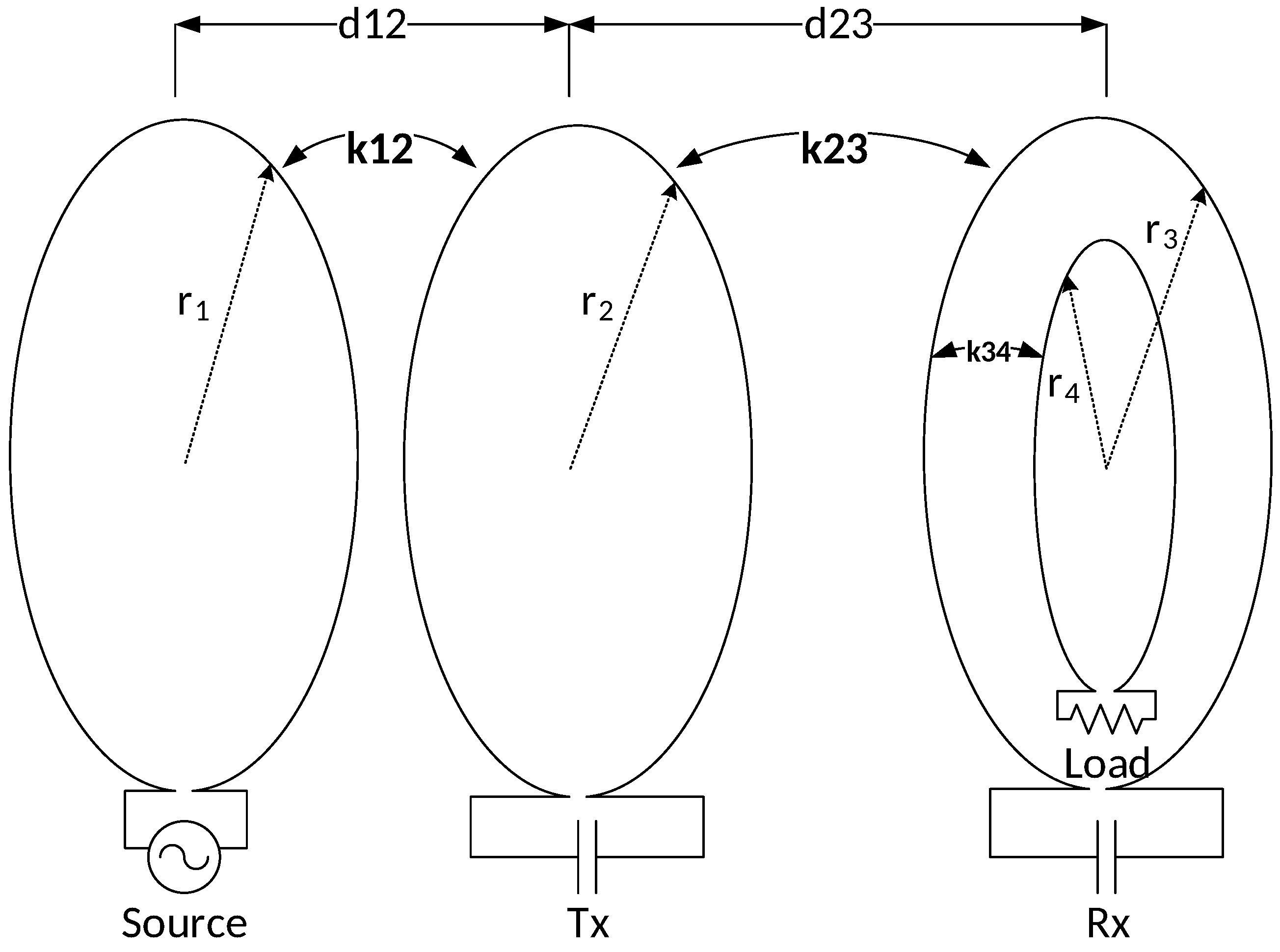
The hybrid WPT model proposed in this study is shown in
Figure 1. This system merges two different wireless transmission system concepts. The transmitting end is designed using the SCMR concept, where the source loop is placed outside the Tx loop in order to provide the flexibility of changing distance between the two loops. On the other hand, the receiver implementation is based on the CSCMR concept, where the load loop is placed concentrically inside the Rx loop. This concept significantly shrinks the size of the receiver end while the coupling between the two coils remains fixed.
For instance, when the distance between Tx and Rx () is changed, the coupling factor () varies accordingly. In order to compensate the corresponding change to maximize the system efficiency, the coupling factor () must be simultaneously altered. According to the CSCMR concept, the coupling factor () remains fixed; hence, only the coupling factor can be changed by adjusting the distance between the source and Tx loops (). Therefore, a relationship between the two distances has to be expressed.
3. Theoretical Analysis of Strongly-Coupled WPT Systems
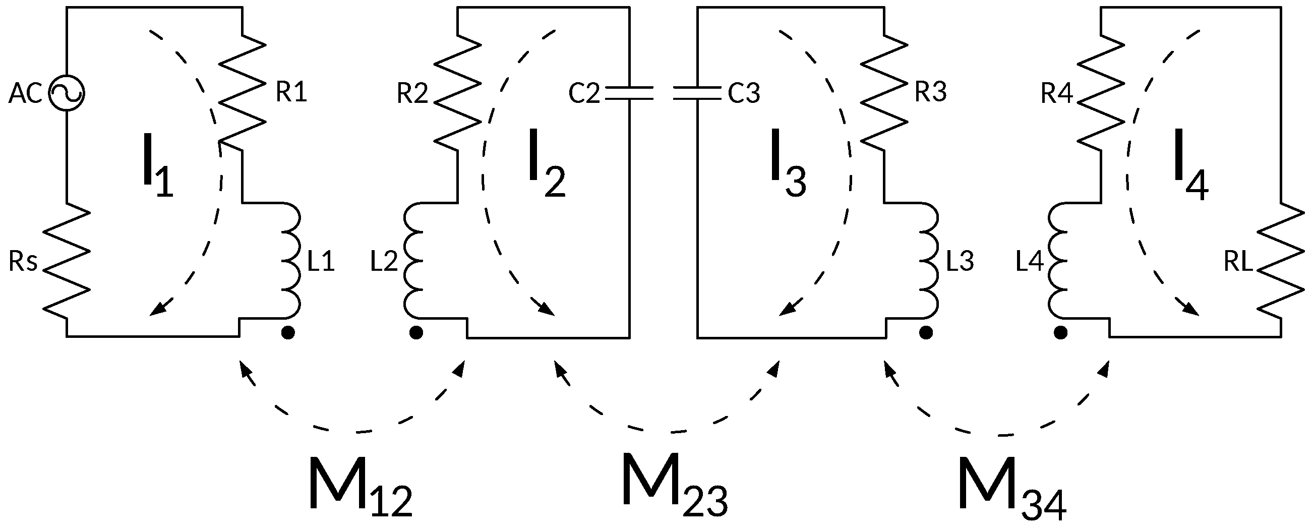
Both conventional CSCMR and SCMR approaches consist of four loops, namely source loop, load loop, Tx and Rx loops. Both Tx and Rx loops are designed to oscillate at the same frequency, and therefore, the quality factor (Q) between the two loops is maximized. This ensures that the power transmission between these loops is maximal while the loops are connected together via electromagnetic coupling. The system can be described by an equivalent circuit diagram as shown in
Figure 2, which illustrates the hybrid systems with two pairs of resonators. From it, a four-port network model can be derived, based on Kirchoff’s voltage law [
29,
30].
The electromagnetic induction field (H) for one of the parallel coaxial loops can, as follows based on Ampere’s law and Faraday’s electromagnetic induction law [
31,
32], be shown as:
where
d represents the distance between the two loops,
represents the radius of
y-th loop and
is the current through the
x-th loop. It is worth noting that Equation (
1) is more accurate at short distances. However, in order to simplify the analysis in this study, we approximate the mutual inductance (M) between the
x-th and
y-th loops including the area enclosed by the coil [
33,
34], as:
where
and
represent the radius of the
x-th and
y-th loops, respectively and
donates the permeability of free space.
stands in for the area of the
y-th loop and can be mathematically expressed as
.
For the Rx elements of the CSCMR system, which consist of two coaxial loops placed concentrically on the same plane, the magnetic field is usually attributed to the larger loop. Therefore, when the distance
= 0, the mutual inductance can be simplified as:
where
. A coupling coefficient between the two loops can be expressed as:
The current in each circuit can be calculated by applying Kirchoff’s voltage law. Therefore, the scattering parameter
, which represents the ratio between the signal at the output port and the injected signal at the input, can be calculated as:
Combined with Equation (
4), the
parameter can be given as:
where:
and
,
,
and
are the loop impedances of the four coils and can be calculated as:
where
,
and
represent total resistance, the equivalent inductance and external capacitance of the
x-th loop, respectively.
In order for the system to function at its maximum efficiency, the resonant frequency can be calculated as:
For the system to work at maximum efficiency, resonant frequency (
) is calculated as:
It is also important that the
Q of the Tx and the Rx loops be high [
30]. The
Q of the
y-th loop can be expressed as:
where
denotes the angular frequency, which can be calculated as
in terms of
.
4. Numerical Analysis
The efficiency of both the CSCMR and SCMR systems strongly depend on the geometrical parameters of the loops. The above system has been designed to have its maximum operating distance of 12 mm when it operates at a frequency of 7.2 MHz. The radius of the source loop, Tx loop and Rx loop,
, was calculated from Equations (2) and (3) and set at 30 mm. As calculated in [
35], the system will achieve the maximum distance when the coupling factor between Rx and load loops
is equal to 0.1. To ensure that the coupling factor
matches the requirements, the radius of the load loop
was calculated as 5 mm, and its inductance was set as
H. In addition, to ensure that the Q requirement between the two loops is fulfilled, the inductance of Rx is set to
H. From Equation (
9), the capacitance of the Rx loop can be calculated as
pF, so that the required loop resonating frequency is achieved.
The inductance of the Tx loop
was set at
H to ensure that the coupling factor and quality factor requirements are met. The desired capacitance of the Tx loop was calculated from Equation (
9) and set at
pF to ensure that the requirements for resonant frequency are met. The calculated values of the loop elements are presented in
Table 1.
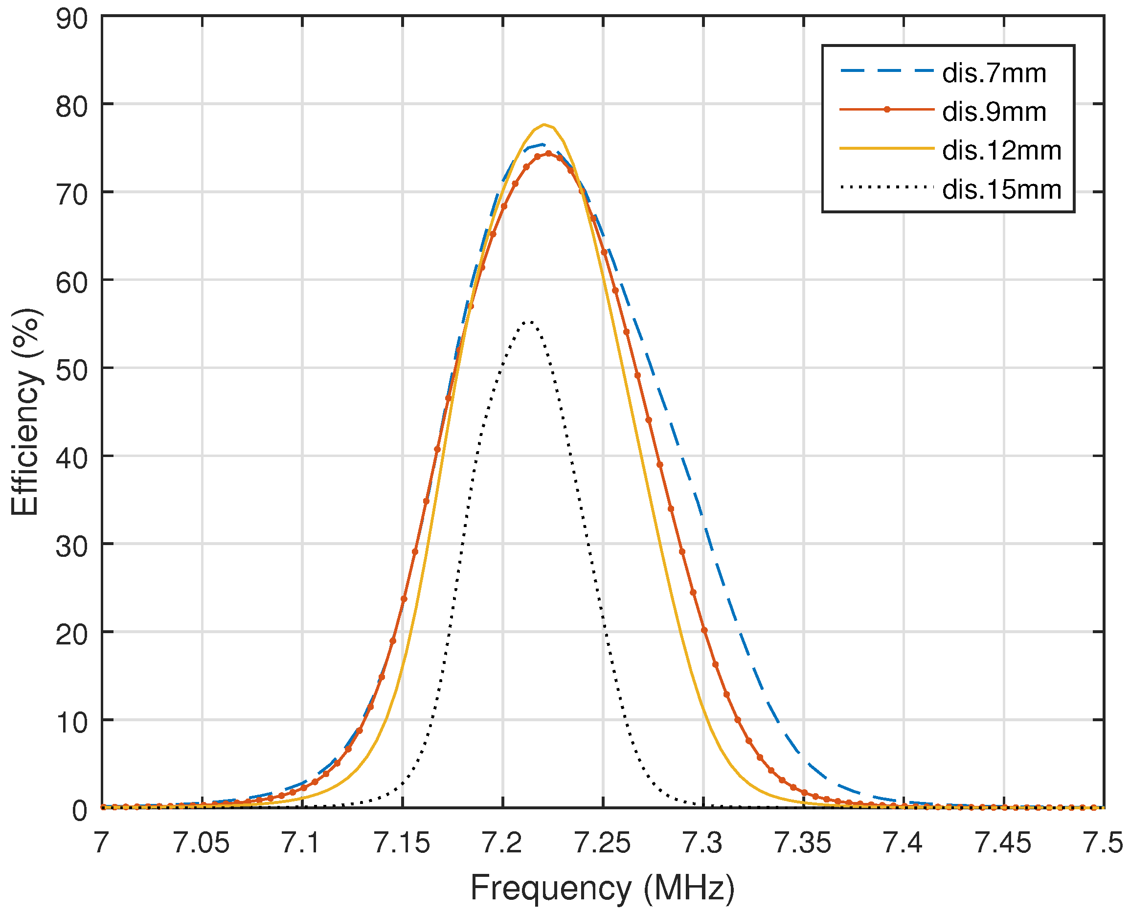
Figure 3 shows that the maximum efficiency of 84% is obtained for the system when the distance between the Tx and Rx is equal to 12 mm. In this case, the distance between the source and Tx loop is equal to 3.4 mm, and therefore, the coupling factor
is equal to 0.1.
Figure 3 also demonstrates the frequency splitting phenomenon when the load power split from a single peak to a double peak. The phenomenon is an increasing coupling factor between the Rx and Tx loops when the distance between them
decreases to a critical point.
Our analytical model was used to study the impact on the system efficiency due to the alternations of the distances and on the efficiency of the system. In addition, it was reviewed how the impact can be used to maintain the maximum efficiency at various distances between Tx and Rx without altering the transmitting frequency.
From
Figure 3, it is also evident that the maximum efficiency appears when the distance between Tx and Rx loops is equal to 12 mm, and therefore, the coupling factor between them can be calculated as
, using Equations (2) and (4). The coupling factor between the source loop and Tx is equal to 0.1. From the two known coupling factors, the relationship between distances
and
can be calculated from Equations (2)–(4) as:
After substituting all of the known variables into Equation (
12), the relationship between the distances
and
can be derived as:
The relationship between the distances in Equation (13) is simulated in MATLAB, and the obtained results are presented in
Figure 4. It is evident that with the right calculation of the relationship between
and
, the maximum power transmission of the SCMR system can be also achieved at comparably shorter distances than the system’s maximum range. Eminently, the transmission frequency remains unaffected within the whole transmission range, which eliminates the necessity of matching circuits and tuning capacitors [
36].
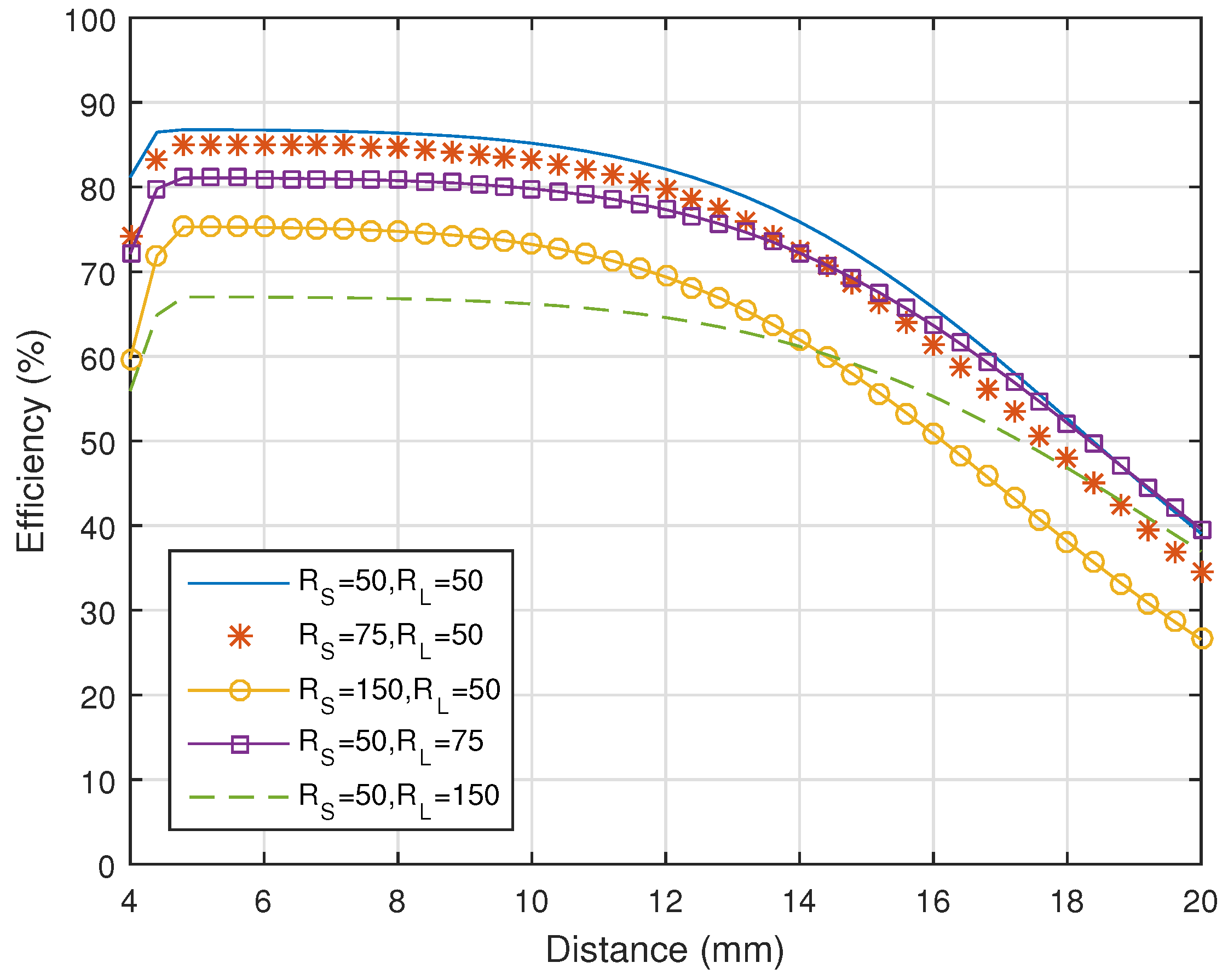
Figure 5 represents the maximum efficiency of the system if different load and source resistances are applied. While the resistance of the source does not have a big impact on maximum efficiency, the impact of increasing load resistance is more significant. In order to improve the performance, where the impedance of the source loop does not match the impedance of the load loop, various impedance matching techniques can be used [
37,
38]. However, the matching algorithms are not compulsory in this study since this experiment was carried out using a signal generator and spectrum analyser with the source and the load having 50
input impedances.
5. Experimental Setup
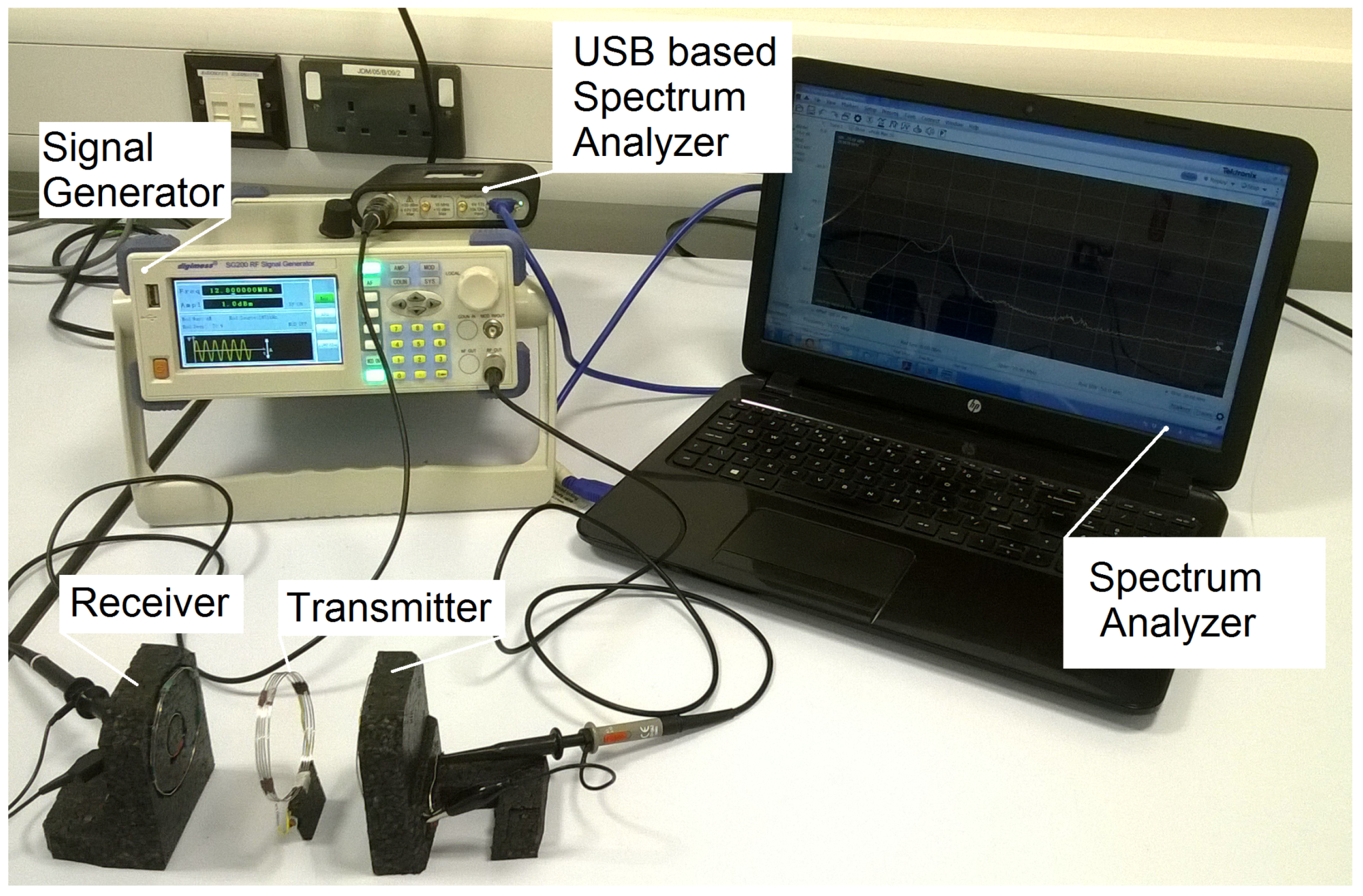
In this section, an experimental setup is presented and is then utilized to explore the impact of various system parameters on the performance. In order to verify the calculated results, an appropriate system was built to comply with the calculations’ model. The two loops forming the transmitter have the same size forming the SCMR system design, and the other two loops are embedded, forming the CSCMR design receiver, as shown in
Figure 6.
5.1. System Design and Measurement
The transmitter consists of the source and TX loops. The source loop is made of a 2.3-turn, silver-plated copper wire, while the Tx loop is made of the same wire and contains 5 turns. The receiver side of the system is made using the same wire where the Rx loop contains 1.6 turns, and the load loop is made of 1.2 turns of the wire. Ceramic capacitors were used to tune the loops to the same oscillating frequencies.
For measurement purposes, a signal generator was used to send various frequencies to the source loop, while the response was measured using a USB base spectrum analyser. Finally, the measured results were displayed using computer-based software communicating with the spectrum analyser.
5.2. System Maximum Efficiency
According to the calculation, an optimal design appears when the distance
is equal to 3.4 mm. In this scenario, the maximum efficiency can be achieved when the distance
is equal to 12 mm. The graphical representation in
Figure 7 is plotted using the measurements and exhibits the maximum efficiency at a distance equal to 11.8 mm. The maximum efficiency of the obtained experimental setup is 79%, which is comparable, to some extent, to the 84% efficiency calculated in
Section 2. The difference can be attributed to the displacement, the shapes of the coils and variation in the electronic components. The instrument used during the testing process can also have effects on the experiment.
Based on the comparison between the measurements and the calculations, the designed system consists of a resonant frequency 20 kHz higher than the calculated one and it also appears to be at 7.22 MHz, as shown in
Figure 8. The difference in the oscillating frequencies between the calculated and measured systems appears due to the tolerance of the elements that are used in the practical application and mathematical formula approximation. In addition, the inductors that were used to fulfil the experimental purpose may also have different inductance values than the calculated values.
5.3. Combined System Efficiency
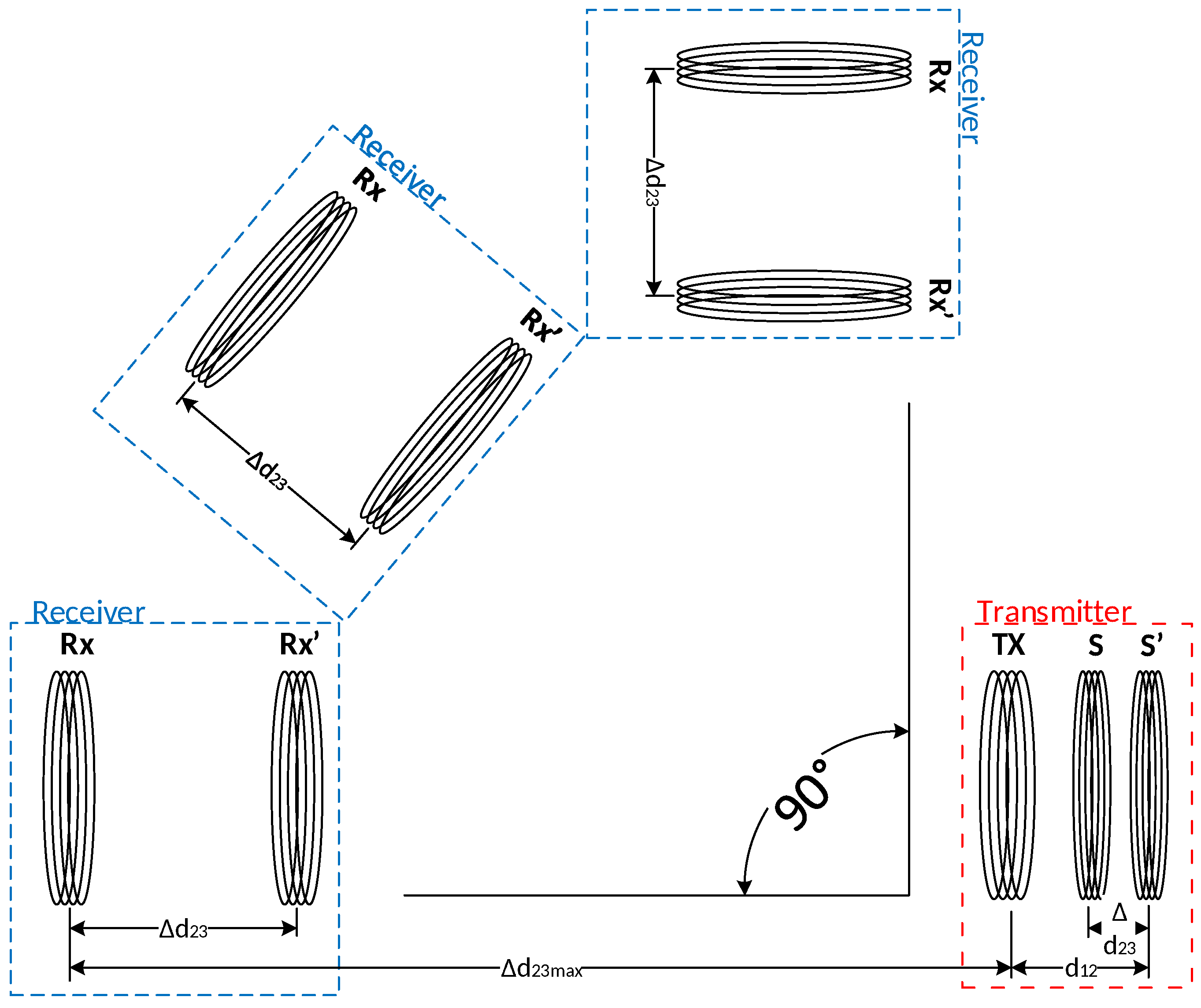
In order to achieve the maximum efficiency, the distance between the source loop (S) and Tx has to be adjusted according to the distance between the Tx and Rx loops as calculated in Equation (
12). As presented in
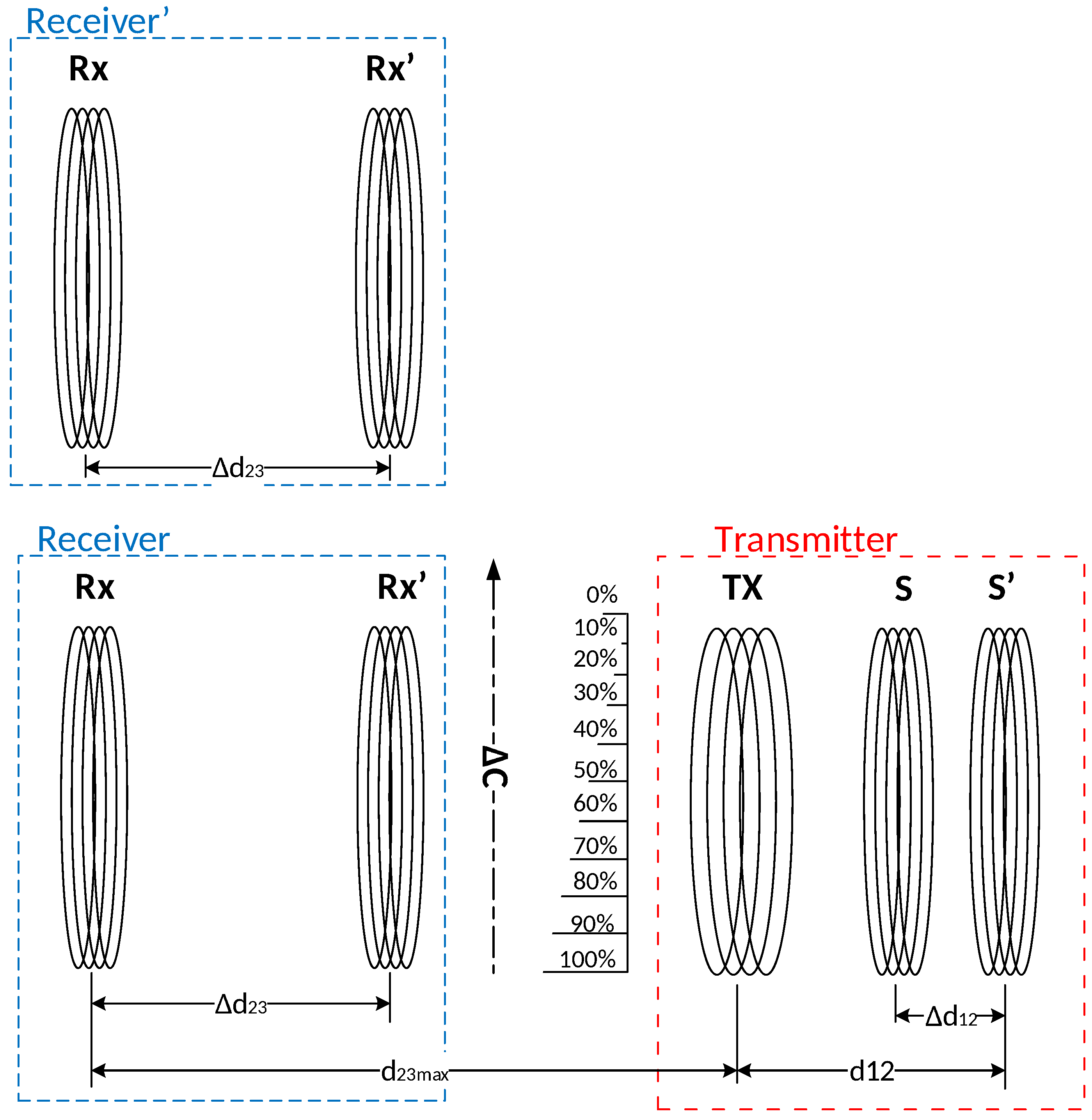
Figure 9, the displacement
between the Tx and Rx loops was compensated by adjusting the distance between S and Tx for
in order to achieve the maximum efficiency. The RX loop in
Figure 9 represents the receiver loop (Tx) with the embedded load loop, and
represents the maximum distance between the transmitting and receiving loops.
Figure 10 illustrates a set of measurements commissioned via a combined CSMR-SCSMR system, which exhibits the maximum efficiency over higher distances.
In order to justify the calculated results, the maximum distance
was measured at the point where the system demonstrated its maximum efficiency along with the random distance
. A numerical comparison between the measured and calculated results is presented in
Table 2.
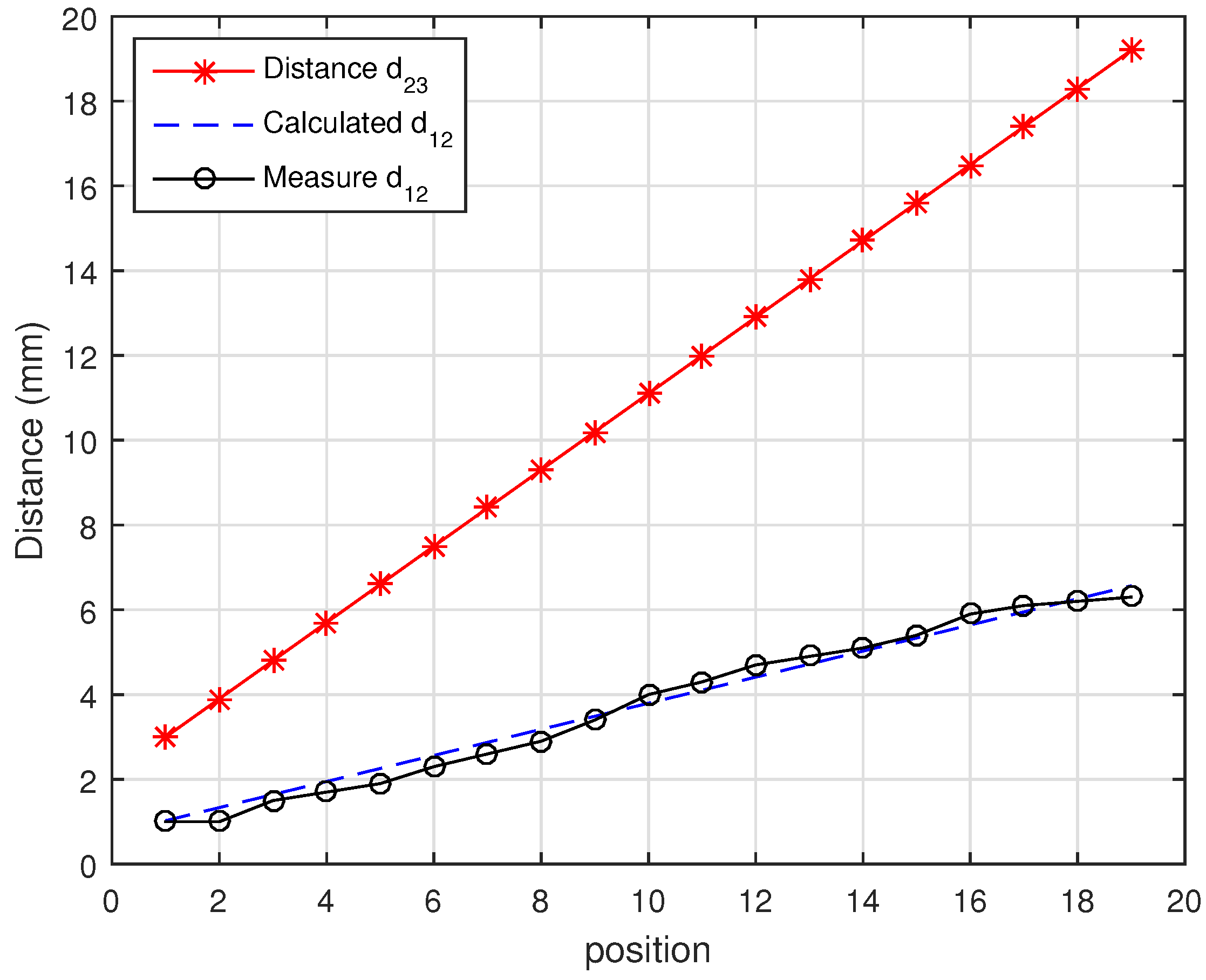
Figure 11 shows a graphical presentation of a comparison between the random distance
and the measured value of
against the calculated value,
.
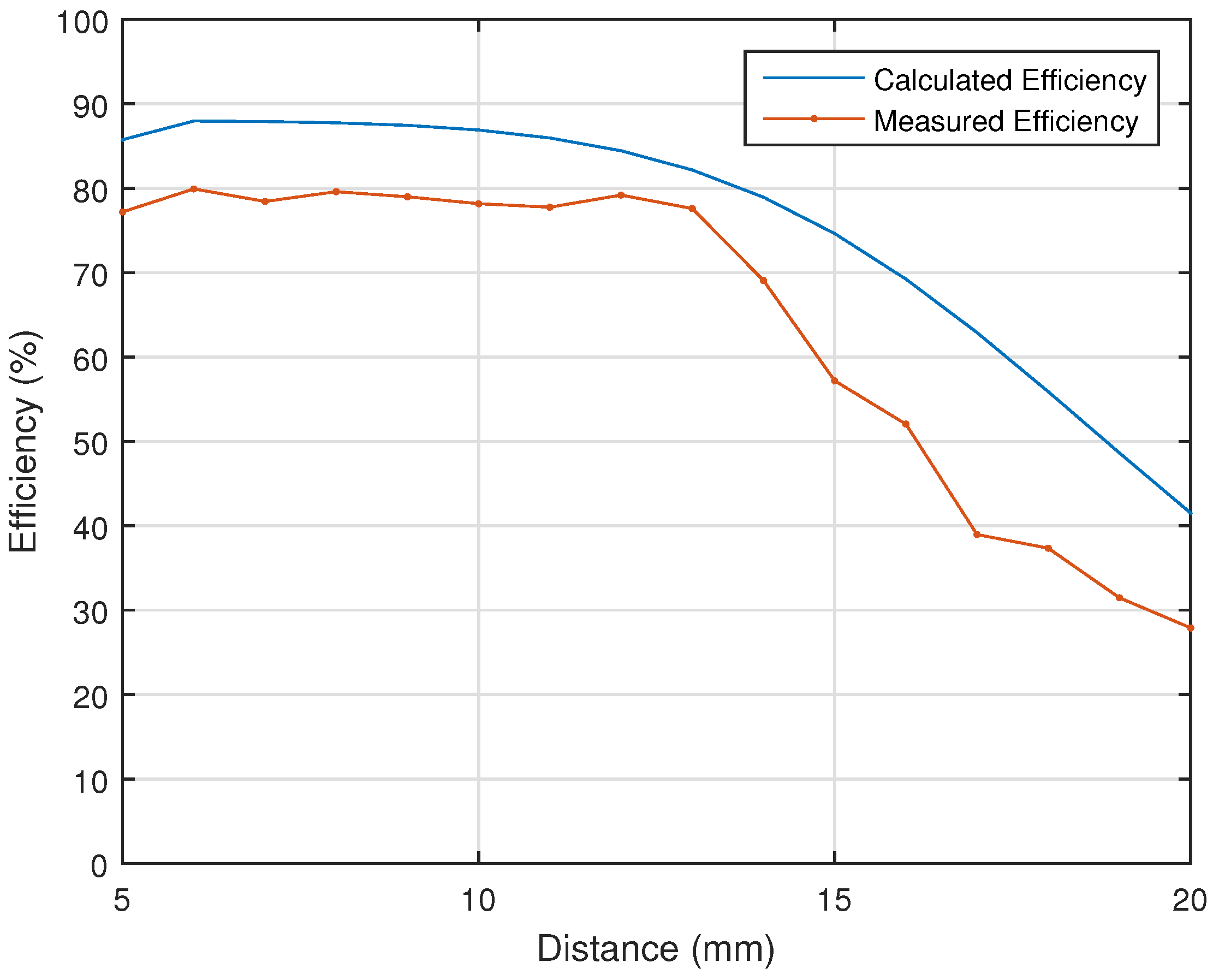
The efficiency of the system was measured, combining the pre-measured and calculated data to achieve maximum efficiency. In
Figure 12, the measured efficiency is compared to the calculated one of the system for multiple random distances, which fits well with the calculated pattern of
adjustments. It is also evident that the system could demonstrate further higher efficiencies than the obtained maximum efficiency, at shorter distances than the higher distance.
5.4. Angle Coverage
The position angle of the transmitter and receiver is also another crucial factor that may impact the system efficiency. In order to measure the efficiency, the angle of the receiver was constantly changed according to the angle of the transmitter, which varied between 0
and 90
, as illustrated in
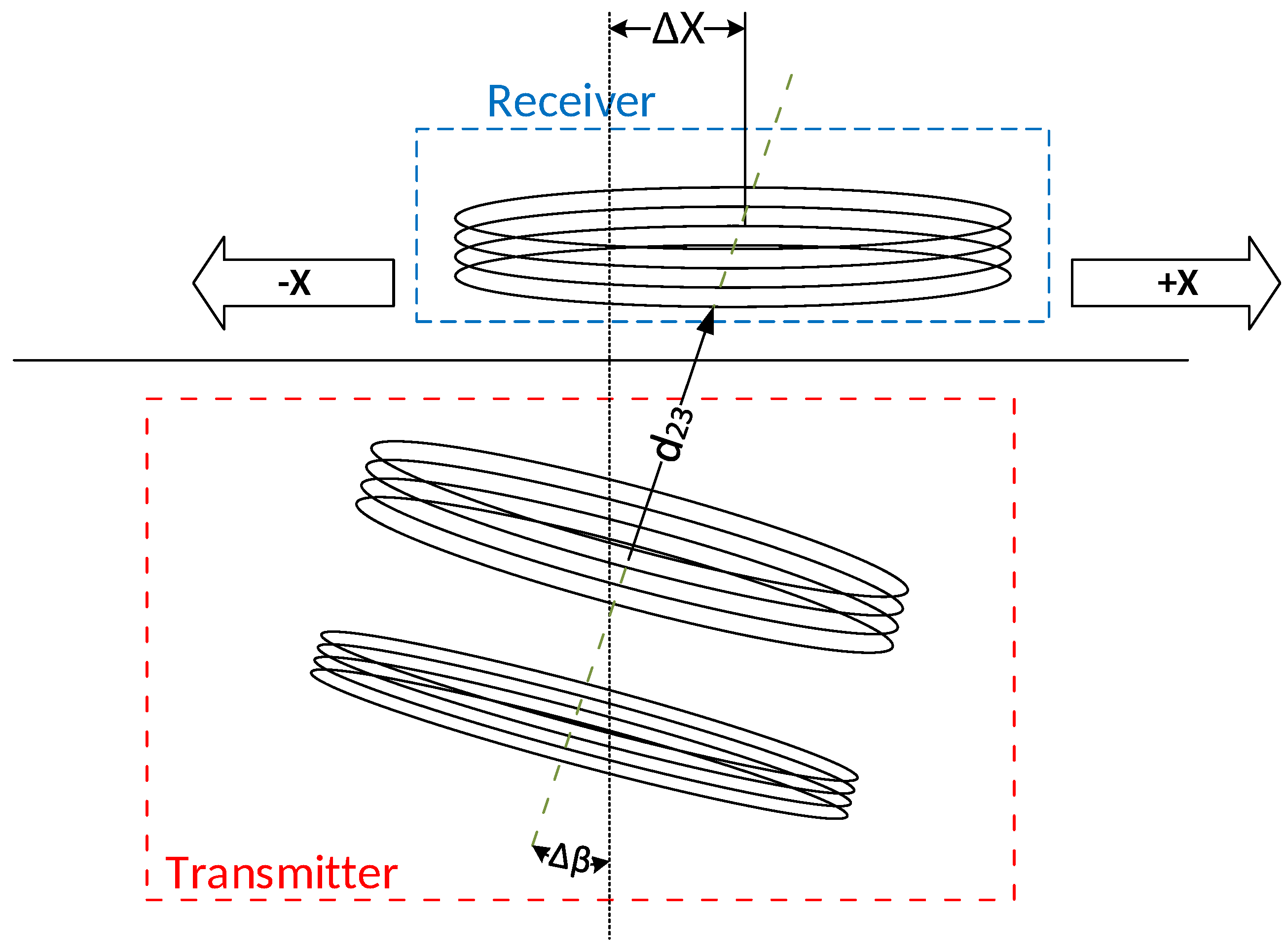
Figure 13. The position of the receiver was also placed at various distances according to the transmitter. For instance, as shown in
Figure 9,
indicates the change of the distance between the RX’ to the previous RX position, which is 1 mm.
indicates the distance between the final RX position and the Tx, which is 20 mm for our measurements.
Simultaneously, the distance between the Tx and S was adjusted
according to the changes made, distance-wise between the Tx and the RX
; see
Figure 13. This further indicates the changes made to distance
to achieve the highest efficiency according to the previous measurements. The receiver placement was changed for
according to the previous measurements, and the measurement was repeated for new alignment.
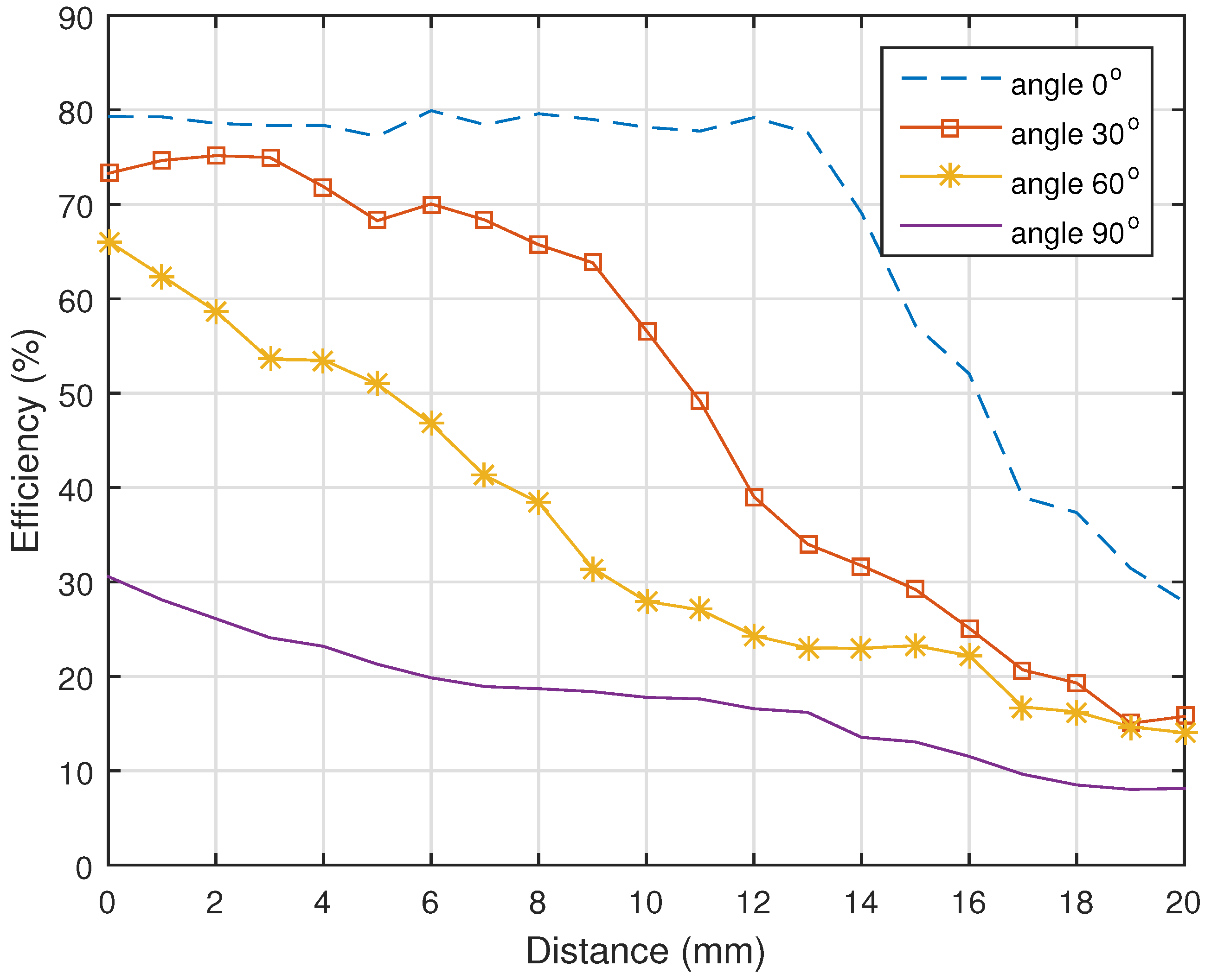
As
Figure 14 indicates, the maximum efficiency drops in accordance with the angle at which the transmitter is being placed. The greater the angle between transmitter and receiver, the lower the efficiency of the charger is and vice versa. It can also be seen that the angle above 30% highly affects the charging efficiency, as well as the distance at which the charger operates. Furthermore, the angle above 60% reduces the working range of the charger to a few millimetres and drastically decreases the efficiency.
From the measurements, it is evident that for the charger to have high efficiency and the highest possible distance covered, the angle placement must be lower that 30%.
5.5. The Impact of the Coils’ Misalignment
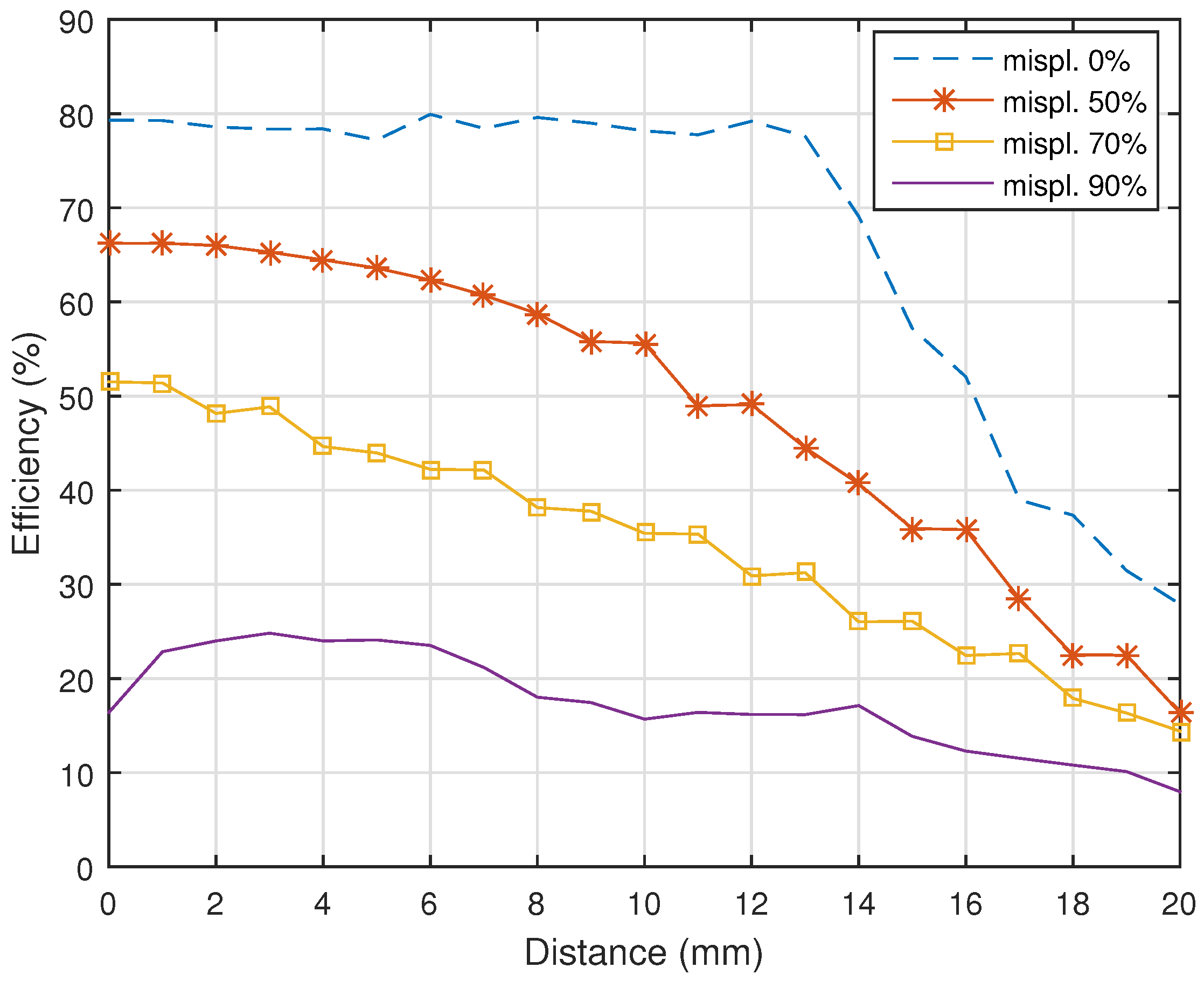
A misalignment between the transmitter and receiver coils also plays an important role of relevance to the system efficiency. As presented in
Figure 15, the measurements were carried out by changing the position of the coverage between the transmitter and receiver loops from 100% coverage down to 10%. The measurements were commissioned at 0%, 50%, 70% and 90% misplacement. The distance between Tx and RX was also altered by
mm, up to
, which was equal to 20 mm. The distance between Tx and S was also altered accordingly by
, in order to maximize the system efficiency.
As for the angle covered, the efficiency drops according to the misalignment that occurred. Interestingly, the effect on the efficiency due to the misalignment was indicated as up to 60%, which does not seem to have massively impacted the overall system efficiency. However, over 60% misalignment within the coil structure has degraded the system efficiency drastically while misalignment over 90% has caused severe efficiency drops.
6. Charger Efficiency Based on the Measured Results
Our proposed wireless power charger design is based on real-time measurements. The charger efficiency is highly sensitive to both coil misalignment and the change of angle between the transmitter and receiver. Moreover, the charger efficiency possesses an inverse relationship with the misalignment and the change of angle. As measured, the maximum distance between the transmitter and receiver where the wireless charger demonstrates its high efficiency is 12 mm with an angle of 20%. Based on the experimental results in
Figure 16, a 50% misalignment may cause approximately 15% of an efficiency drop. From the previous calculation, it can be shown that the starting distance between TX and Rx will be 5 mm.
The charger transmitter circuit adjusts the distance between the source and transmitter loops to fulfil the changing position requirements of the receiver. However, in order to perform the charging efficiently, the charger must be capable of adjusting the angle to reach the receiver, as shown in
Figure 17.
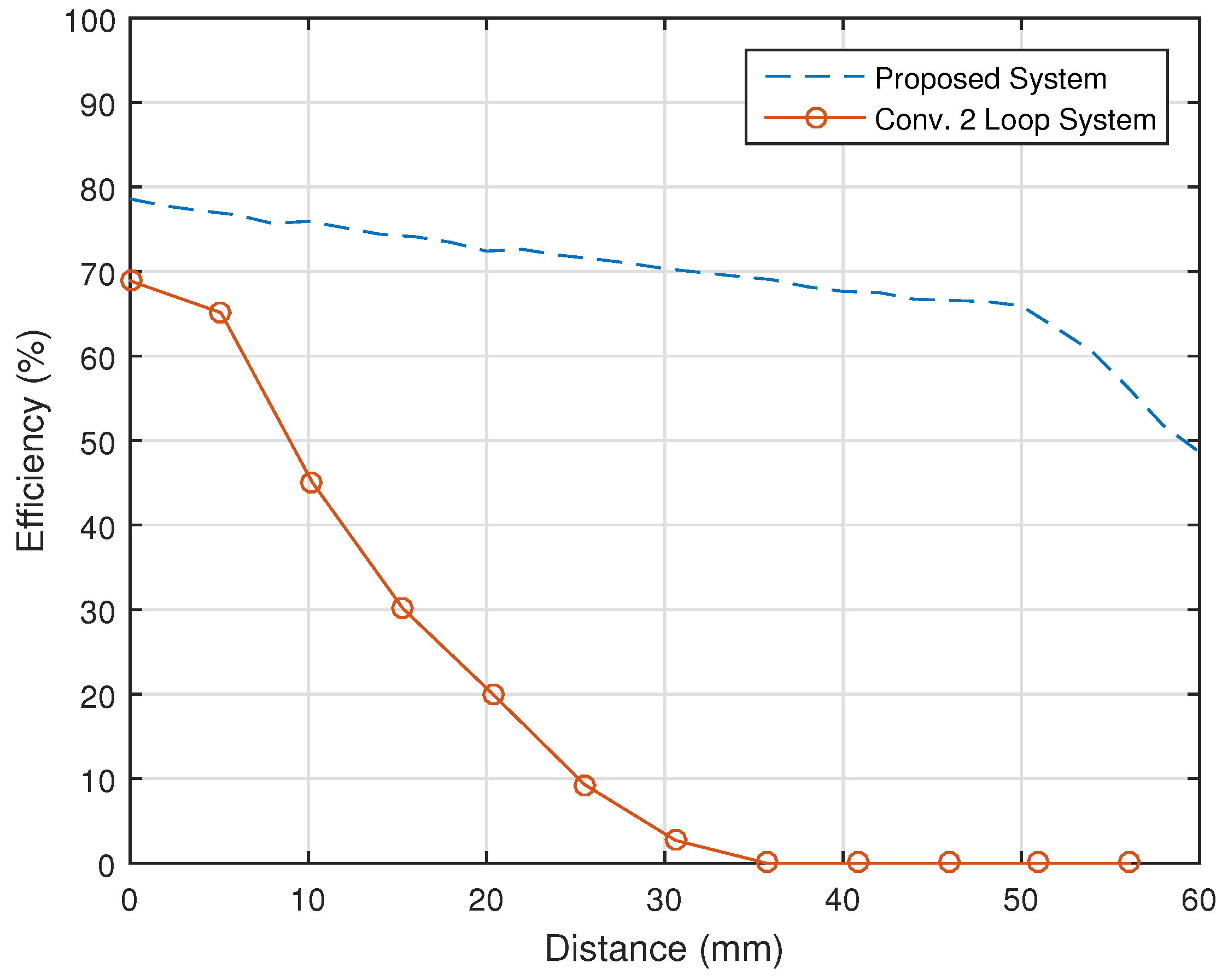
Nevertheless,
Figure 18 indicates that the proposed system exhibits a tolerance of misalignment up to a 50-mm radius within the charging pad where the efficiency remains at or above 60%. According to calculations, the efficiency at a 50-mm displacement will be 67.6%, while the efficiency at full coverage is just above 79%. Likewise, the overall efficiency loss remains in the range of 10%, providing more flexibility, allowing the device to be charged efficiently within the 50-mm radius. For the sake of comparison,
Figure 18 also shows results for the conventional 2-coil system. It is clear that the proposed system always has better performance, and the improvement gap becomes more significant as the distance becomes larger.
At this end, it is worthwhile mentioning that the proposed system may not be always the best option in practical implementations due to its size. However, the improved efficiency and extended operating bandwidth of this system can marginalize the size issue. The other attractive advantage of the proposed configuration is its ability to perform well over shorter distances, which is a main drawback of other existing coil resonant systems.


 ,
, 


