
Robust Clamping Force Control of an Electro-Mechanical Brake System for Application to Commercial City Buses

Abstract
:1. Introduction
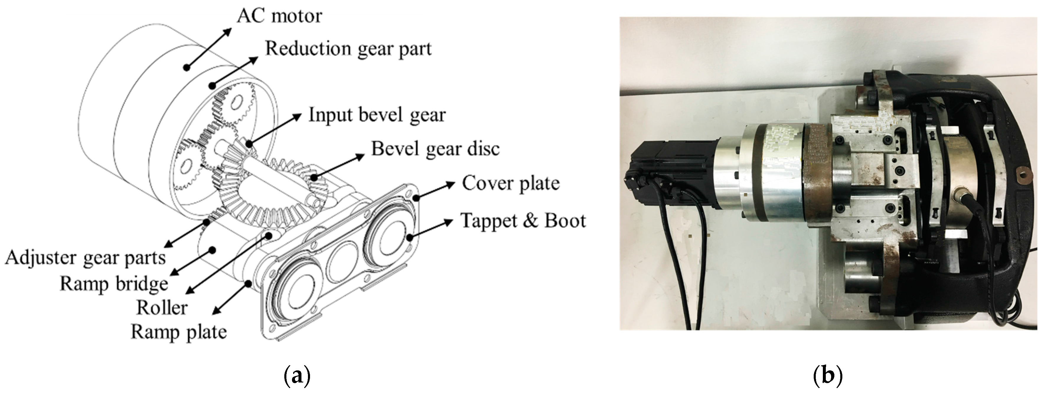
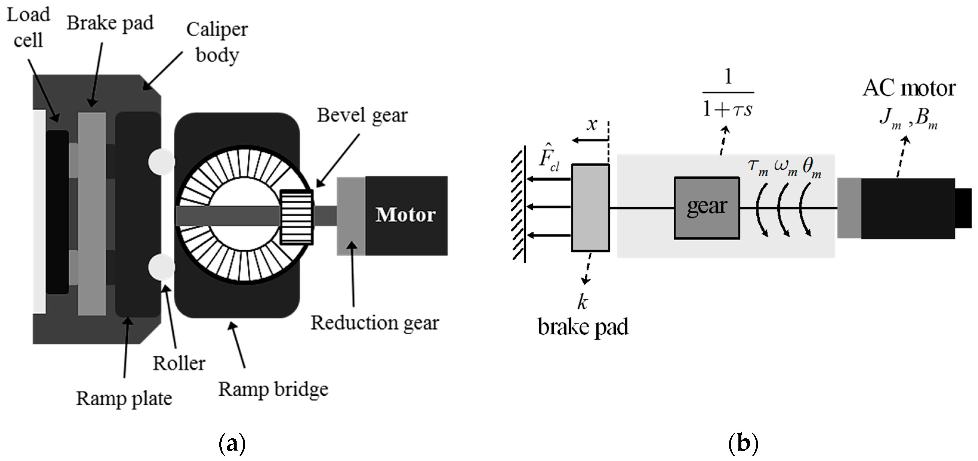
2. System Modeling of an EMB System
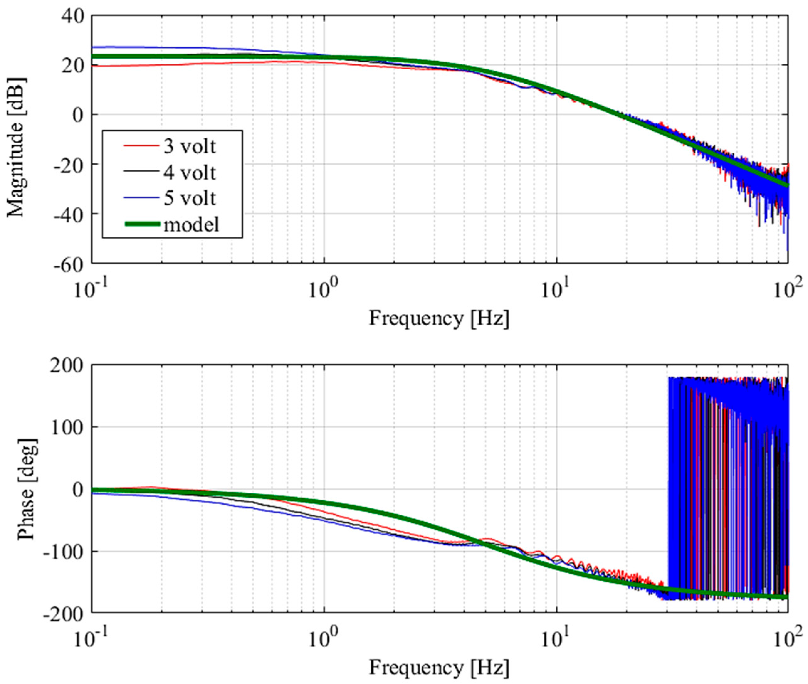
Dynamics Model
3. Design of a Sensor-Less Robust Controller
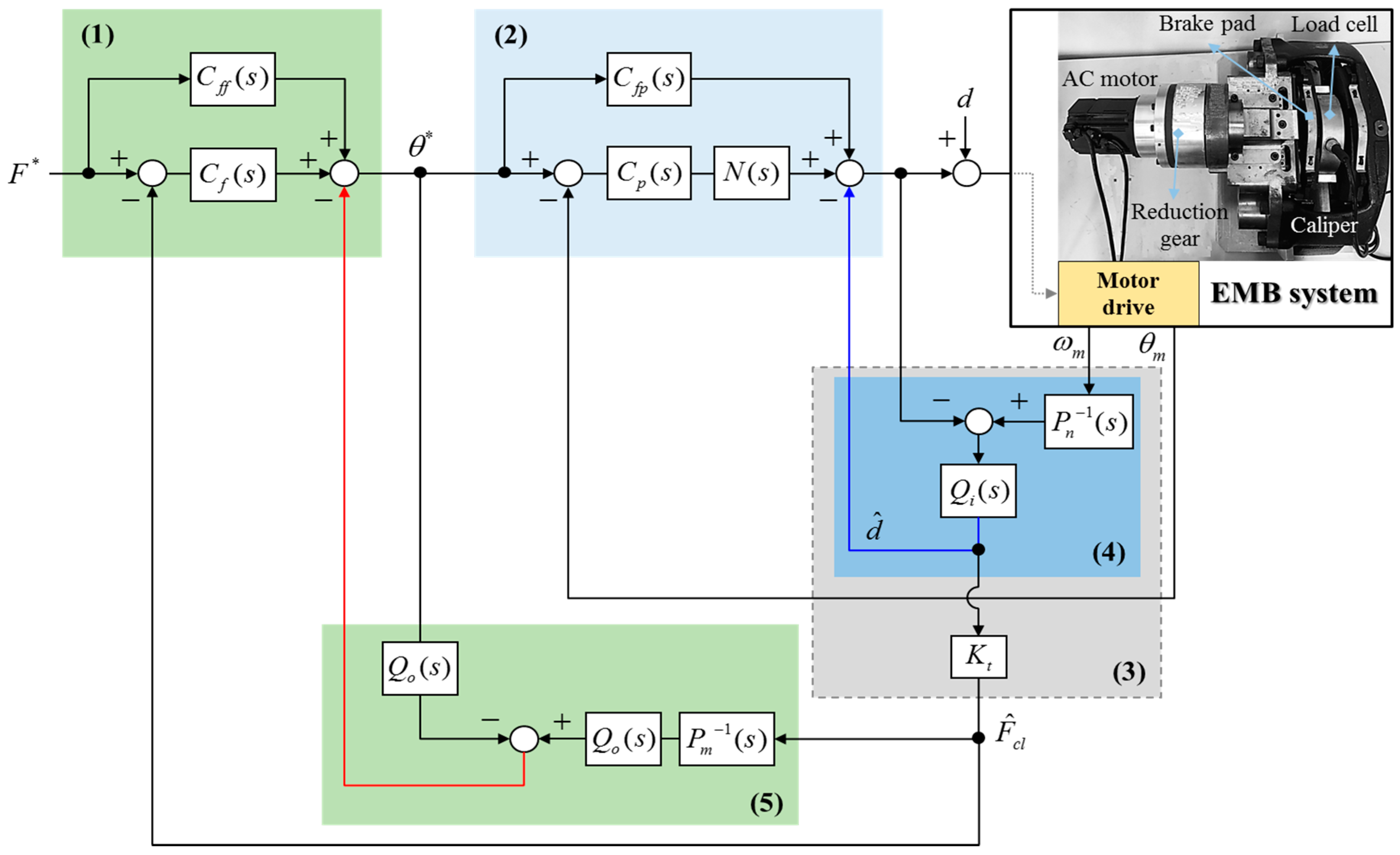
- First, the desired clamping force is generated by a driver’s brake pedal command. Note that the desired clamping force can be calculated by using the brake pedal stroke sensor.
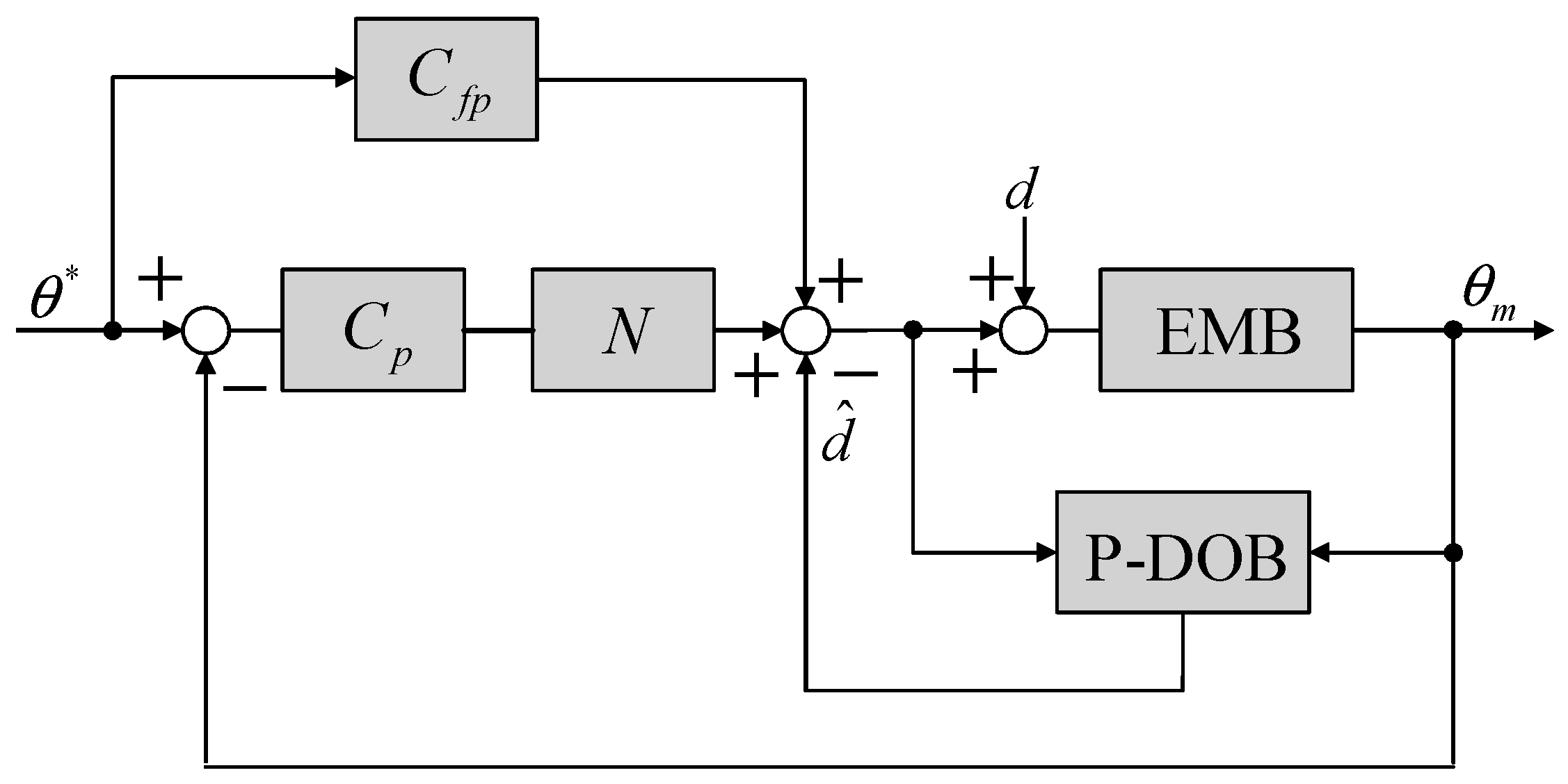
- Second, the 2-degree-of-freedom position controller is designed based on the defined nominal motor model for improving the position tracking performances and an inner-loop disturbance observer (i.e., called a position-mode DOB) is designed for making the position controller robust against external disturbances.
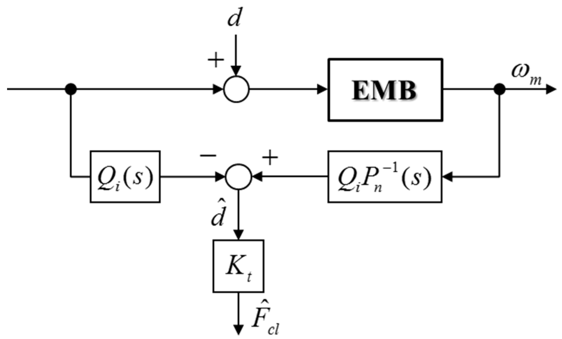
- Third, a CFO is designed based on a nominal motor model and a reduction gear ratio.
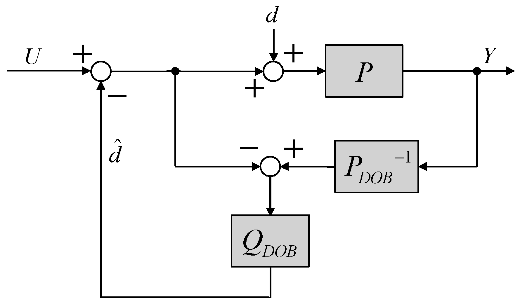
- Forth, the outer-loop disturbance observer (i.e., called a force-mode DOB) is designed to compensate for model variations and to reject undesired disturbances. A F-DOB makes the complicated calmping force dynamics behave as a defined nominal clamping force model.
- Finally, the 2-degree-of-freedom clamping force controller is designed by using the nominal clamping force model.
3.1. Design of a Clamping Force Observer (CFO)
3.2. Design of an Inner-Loop Controller: Position Controller
3.3. Design of an Outer-Loop Controller: Force Controller
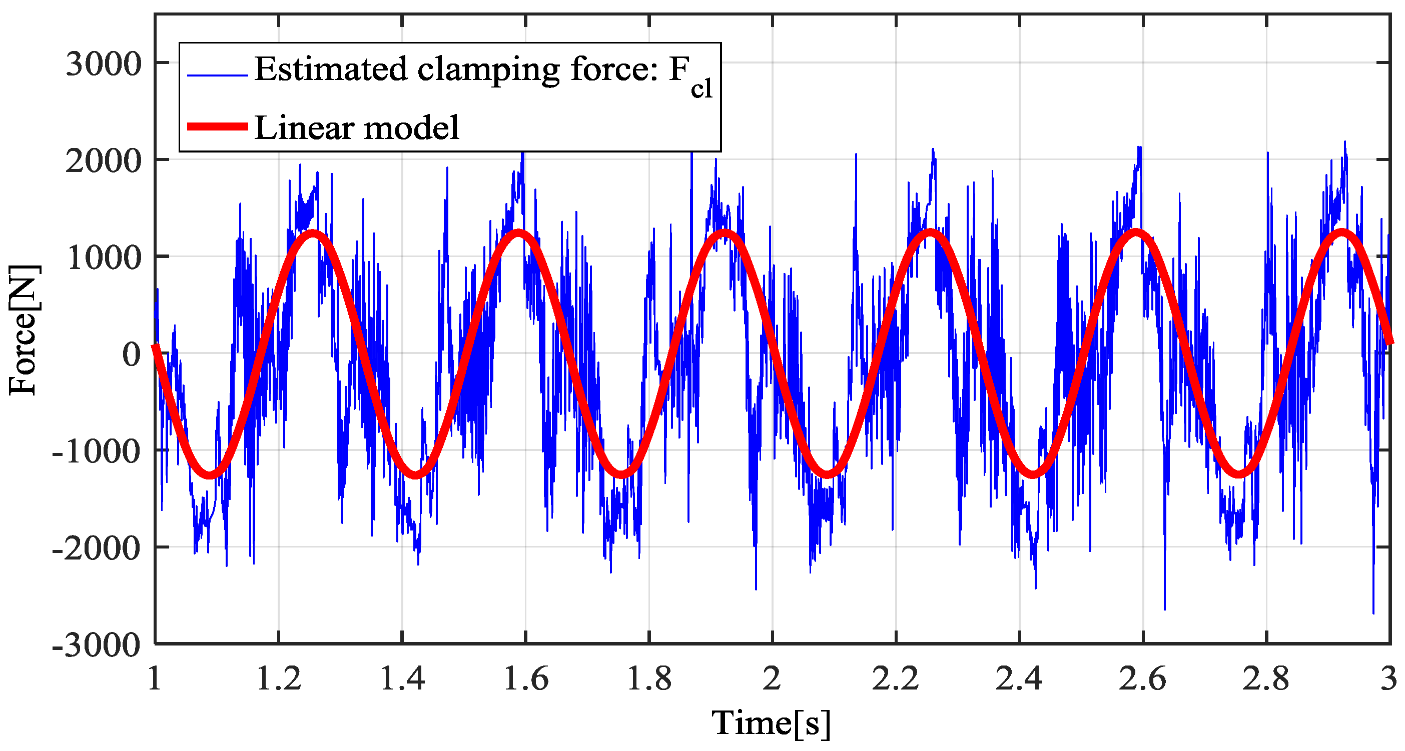
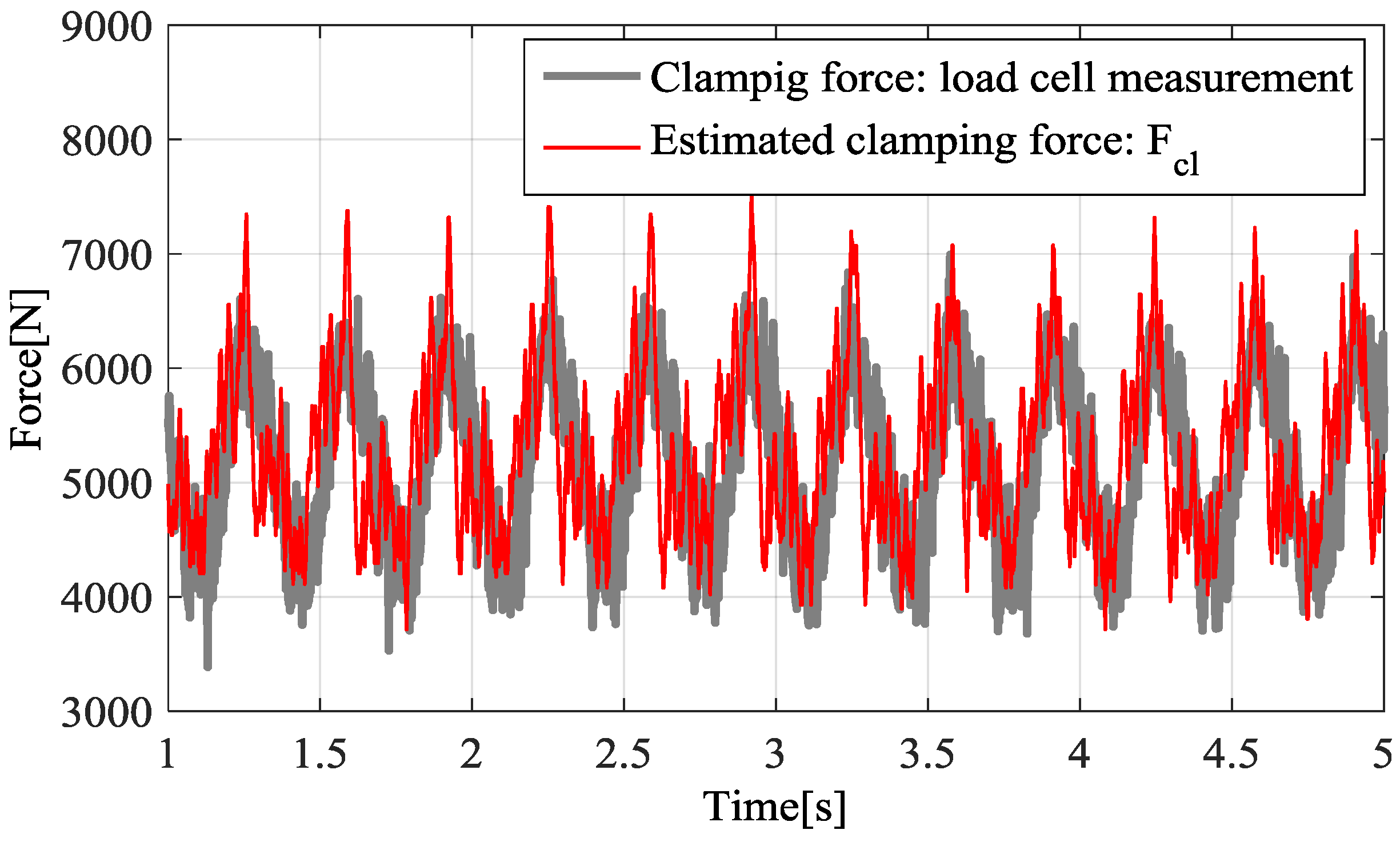
4. Experiments
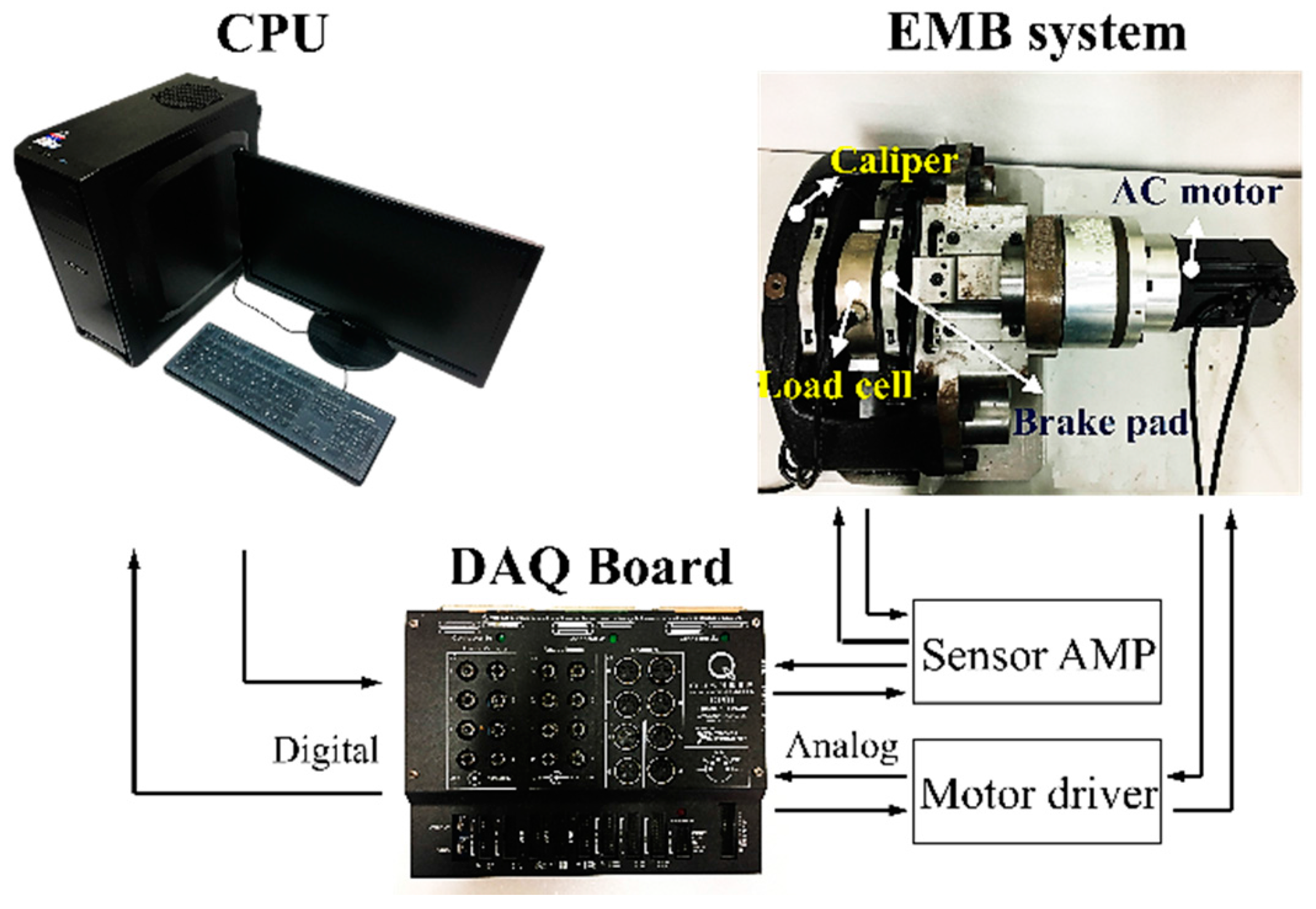
4.1. Experimental Setup
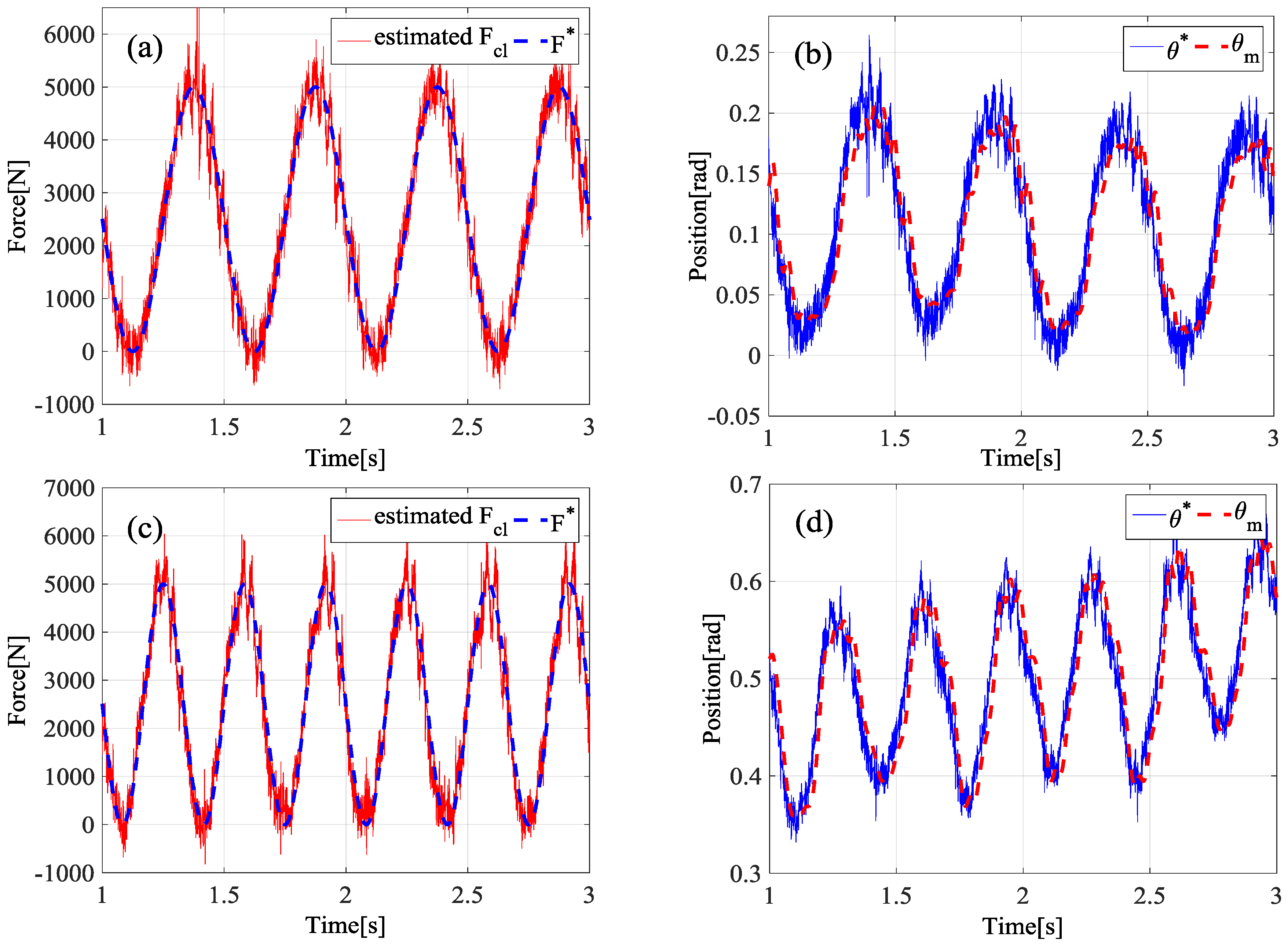
4.2. Experimental Results
5. Conclusions
Acknowledgments
Author Contributions
Conflicts of Interest
Nomenclature
| a damping coefficient in a motor model | |
| a force controller | |
| a position controller | |
| a force feed-forward controller | |
| a position feed-forward controller | |
| external disturbances | |
| estimated disturbances | |
| a clamping force | |
| an estimated clamping force | |
| a moment of inertia for a driving motor | |
| a proportional gain used in the force controller | |
| an integral gain used in the force controller | |
| a proportional gain used in the position controller | |
| an integral gain used in the position controller | |
| a derivative gain used in the position controller | |
| a force gain | |
| a brake pad coefficient | |
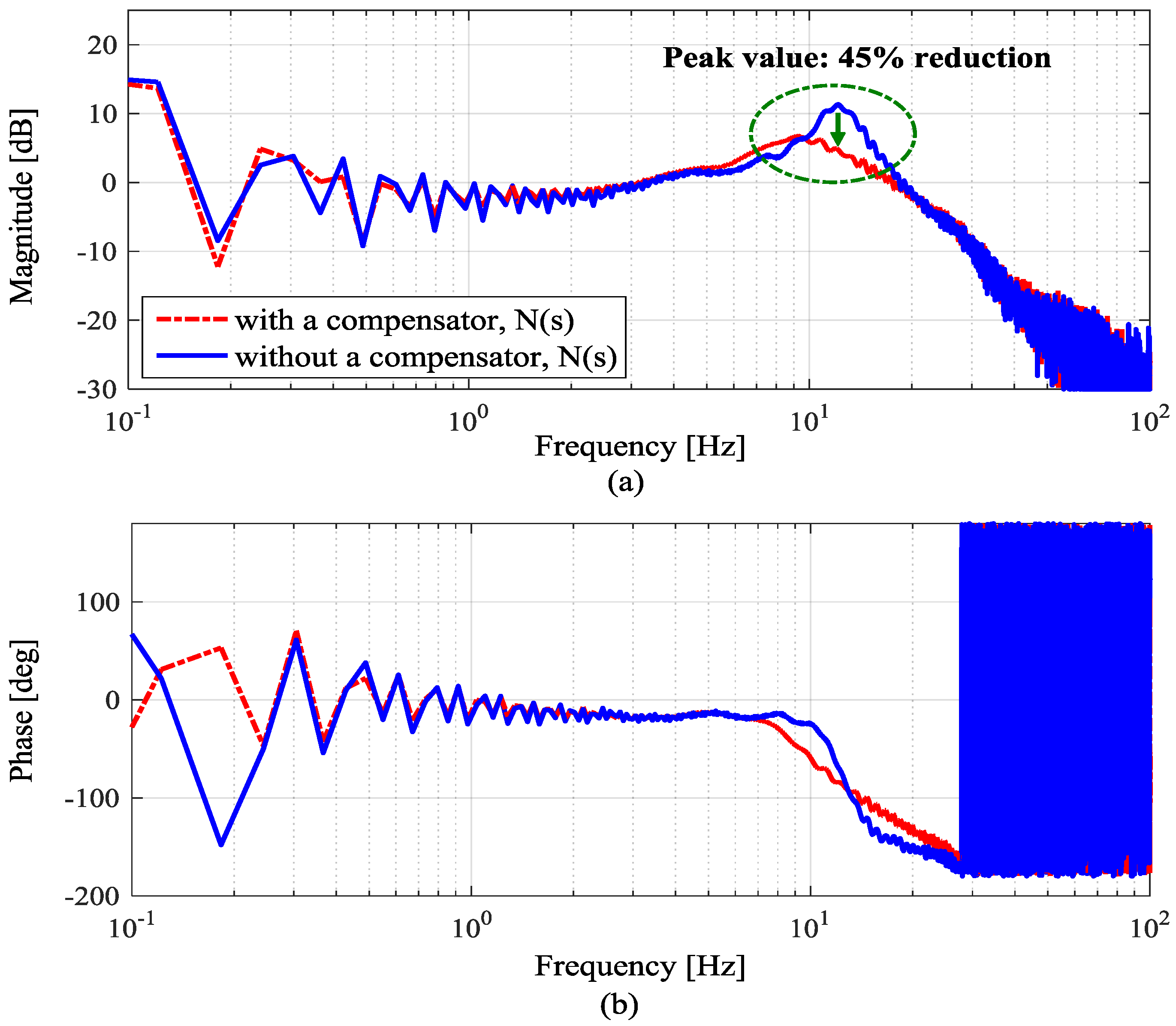
| a residual vibration compensator | |
| a nominal model between and | |
| a nominal model between and | |
| a low pass filter used in an inner position control loop | |
| a low pass filter used in an outer force control loop | |
| an angle of a driving motor | |
| a torque of a driving motor | |
| a time constant | |
| an angular velocity of a driving motor | |
| a cutoff frequency of a feedforward filter used in the position control | |
| a cutoff frequency of a feedforward filter used in the force control | |
| a bandwidth of the residual vibration compensator, | |
| a bandwidth of the force controller | |
| a cutoff frequency of | |
| a cutoff frequency of | |
| a bandwidth of the position controller | |
| stroke of the brake pad | |
| a damping coefficient used in a residual vibration compensator, |
References
- Todeschini, F.; Corno, M.; Panzani, G.; Fiorenti, S.; Savaresi, S.M. Adaptive Cascade Control of a Brake-By-Wire Actuator for Sport Motorcycles. IEEE/ASME Trans. Mechatron. 2015, 20, 1310–1319. [Google Scholar] [CrossRef]
- Anwar, S. Generalized predictive control of yaw dynamics of a hybrid brake-by-wire equipped vehicle. Mechatronics 2005, 15, 1089–1108. [Google Scholar] [CrossRef]
- Tanelli, M.; Astolfi, A.; Savaresi, S.M. Robust nonlinear output feedback control for brake by wire control systems. Automatica 2008, 44, 1078–1087. [Google Scholar] [CrossRef]
- Savitski, D.; Ivanov, V.; Schleinin, D.; Augsburg, K.; Pütz, T.; Lee, C.F. Advanced Control Functions of Decoupled Electro-Hydraulic Brake System. In Proceedings of the 2016 IEEE 14th International Workshop on Advanced Motion Control (AMC), Auckland, New Zealand, 22–24 April 2016.
- Albatlan, S.A. Effect of hydraulic brake pipe inner diameter on vehicle dynamics. Int. J. Automot. Technol. 2015, 16, 231–237. [Google Scholar] [CrossRef]
- Kim, S.; Huh, K. Fault-tolerant braking control with integerated EMBs and regenerative in-wheel motors. Int. J. Automot. Technol. 2016, 17, 923–936. [Google Scholar] [CrossRef]
- Saric, S.; Bab-Hadiashar, A.; Hoseinnezhad, R. Clamp-Force Estimation for a Brake-by-Wire System: A Sensor-Fusion Approach. IEEE Trans. Veh. Technol. 2008, 57, 778–786. [Google Scholar] [CrossRef]
- Jing, L.; Wang, M.; Rui, H.; Jian, Z. A Design of Electromechanical Brake System Triple-Loop Controllers Using Frequency Domain Method Based on Bode Plote. In Proceedings of the 2011 International Conference on Transportation, Mechanical, and Electrical Engineering (TMEE), Changchun, China, 16–18 December 2011.
- Jo, C.; Hwang, S.; Kim, H. Clamping-Force Control for Electromechanical Brake. IEEE Trans. Veh. Technol. 2010, 59, 3205–3212. [Google Scholar] [CrossRef]
- Lee, Y.O.; Son, Y.S.; Chung, C.C. Clamping Force Control for an Electric Parking Brake System: Switched System Approach. IEEE Trans. Veh. Technol. 2013, 62, 2937–2948. [Google Scholar] [CrossRef]
- Ohnishi, K. A new Servo method in Mechatronics. Jpn. Soc. Electr. Eng. 1987, 170-D, 83–86. [Google Scholar]
- Kurihara, D.; Kakinuma, Y.; Katsura, S. Sensorless Cutting Force Control Using Parallel Disturbance Observer. In Proceedings of the 5th International Conference on Leading Edge Manufacturing in 21st Century, Osaka, Japan, 2–9 December 2009.
- Katsura, S.; Matsumoto, Y.; Ohnishi, K. Modeling of Force Sensing and Validation of Disturbance Observer for Force Control. IEEE Trans. Ind. Electron. 2007, 54, 530–538. [Google Scholar] [CrossRef]
- Oh, S.; Kong, K.; Hori, Y. Design and Analysis of Force-Sensor-Less Power-Assist Control. IEEE Trans. Ind. Electron. 2014, 61, 985–993. [Google Scholar] [CrossRef]
- Ohnishi, K.; Shibata, M.; Murakami, T. Motion control for advanced mechatronics. IEEE/ASME Trans. Mechatron. 1996, 1, 56–67. [Google Scholar] [CrossRef]
- Sehoon, O.; Hori, Y. Sensor Free Power Assisting Control Based on Velocity Control and Disturbance Observer. In Proceedings of the IEEE International Symposium on Industrial Electronics, Dubrovnik, Croatia, 20–23 June 2005.
- Nam, K.; Fujimoto, H.; Hori, Y. Advanced Motion Control of Electric Vehicles Based on Robust Lateral Tire Force Control via Active Front Steering. IEEE/ASME Trans. Mechatron. 2014, 19, 289–299. [Google Scholar] [CrossRef]


© 2017 by the authors. Licensee MDPI, Basel, Switzerland. This article is an open access article distributed under the terms and conditions of the Creative Commons Attribution (CC BY) license ( http://creativecommons.org/licenses/by/4.0/).
Share and Cite
Eum, S.; Choi, J.; Park, S.-S.; Yoo, C.; Nam, K. Robust Clamping Force Control of an Electro-Mechanical Brake System for Application to Commercial City Buses. Energies 2017, 10, 220. https://doi.org/10.3390/en10020220
Eum S, Choi J, Park S-S, Yoo C, Nam K. Robust Clamping Force Control of an Electro-Mechanical Brake System for Application to Commercial City Buses. Energies. 2017; 10(2):220. https://doi.org/10.3390/en10020220
Chicago/Turabian StyleEum, Sangjune, Jihun Choi, Sang-Shin Park, Changhee Yoo, and Kanghyun Nam. 2017. "Robust Clamping Force Control of an Electro-Mechanical Brake System for Application to Commercial City Buses" Energies 10, no. 2: 220. https://doi.org/10.3390/en10020220