Effects of Mixture Stratification on Combustion and Emissions of Boosted Controlled Auto-Ignition Engines


1
Faculty of Mechanical Engineering, Lublin University of Technology, Nadbystrzycka 36, 20-618 Lublin, Poland
2
National Engineering School of Sfax, University of Sfax, Aeroport Road Km 0.5, BP 1169 .3029 Sfax, Tunisia
3
Faculty of Production Engineering, University of Life Sciences, Gleboka 28, 20-612 Lublin, Poland
*
Author to whom correspondence should be addressed.
Energies 2017, 10(12), 2172; https://doi.org/10.3390/en10122172
Submission received: 18 November 2017
/
Revised: 10 December 2017
/
Accepted: 15 December 2017
/
Published: 19 December 2017
Abstract
:The stratification of in-cylinder mixtures appears to be an effective method for managing the combustion process in controlled auto-ignition (CAI) engines. Stratification can be achieved and controlled using various injection strategies such as split fuel injection and the introduction of a portion of fuel directly before the start of combustion. This study investigates the effect of injection timing and the amount of fuel injected for stratification on the combustion and emissions in CAI engine. The experimental research was performed on a single cylinder engine with direct gasoline injection. CAI combustion was achieved using negative valve overlap and exhaust gas trapping. The experiments were performed at constant engine fueling. Intake boost was applied to control the excess air ratio. The results show that the application of the late injection strategy has a significant effect on the heat release process. In general, the later the injection is and the more fuel is injected for stratification, the earlier the auto-ignition occurs. However, the experimental findings reveal that the effect of stratification on combustion duration is much more complex. Changes in combustion are reflected in NOX emissions. The attainable level of stratification is limited by the excessive emission of unburned hydrocarbons, CO and soot.
1. Introduction
The Controlled Auto Ignition (CAI) engine is not an entirely new combustion engine, but rather a new combustion mode. CAI combustion combines the advantages of spark ignition (SI) and compression ignition (CI) combustion, while avoiding their shortcomings. The CAI principle is based on the compression of well-mixed fuel and air just to the point of auto-ignition, and volumetric combustion controlled by chemical kinetics. As a result, the process achieves a comparatively lower combustion temperature, which significantly reduces the NOX emissions. In contrast to conventional CI engines, where air-fuel mixtures are locally rich, in CAI engines the mixture is lean or at least stoichiometric, which results in low soot production and thus reduced emissions of particulate matter (PM) [1,2,3,4]. Due to the low amount of emissions, the use of after-treatment devices for PM and NOX is not necessary. Furthermore, the efficiency of the process can improved because high compression ratios can be applied, and fuel can be highly diluted by air. This helps eliminate throttling losses. Shorter combustion results in a realization process resembling the Otto cycle, and hence leads to increased thermal efficiency. The above combustion characteristics make CAI engines a promising solution to current energy conservation and pollution reduction challenges.
This novel combustion concept was first demonstrated by Onishi et al. [5] and by Noguchi et al. [6] for 2-stroke engines. Najt and Foster [7] the first presented CAI combustion in a 4-stroke engine. Since that time, a lot of effort has been put into understanding and development of the CAI combustion concept. CAI operation has been also investigated using a wide range of fuels [8,9,10,11,12].
CAI combustion has been successfully evaluated at low to medium loads, yet it still poses problems at high loads, for which the rapid heat release rate (HRR) results in a high pressure rise rate (PRR). The approaches to reducing PRR at elevated engine loads are increased fuel dilution by high degrees of boost and/or high exhaust gas re-circulation (EGR) rates [13,14,15,16,17,18].
Although the CAI engine concept relies on volumetric combustion of a nearly homogeneous mixture, the introduction of some fuel stratification can be utilized for control of auto-ignition timing and combustion duration. Apart from compositional stratification, there also occurs thermal stratification because the heat of fuel vaporization reduces the mixture temperature unevenly, depending on the fuel concentration. Additionally, since CAI engines utilize internal gas re-circulation via negative valve overlap (NVO), thermal and compositional stratification can be a result of imperfect mixing of the fresh air and the retained residuals.
Sjöberg et al. [19] simulated combustion of the thermally stratified mixture to demonstrate the effect of temperature distribution on HRR. The results indicated that even 30 K width thermal stratification can significantly decrease the combustion rate, and thus reduce PRR. Rothamer et al. [20] quantified temperature distribution in an optical engine operated in the NVO mode. The results revealed that the standard deviation in the temperature field in the cylinder reached 25 K, due to imperfect mixing of the intake air with retained residuals. Dec et al. [21] applied port injection and direct injection to achieve partial fuel stratification. Stratification proved to be an effective method for reducing the HRR and the resulting PRR; however, only for increased intake pressure. For ambient intake pressure, it was found that the combustion rate was neutral to direct injection timing. Yang et al. [22] also utilized dual injection system, however said authors injected methanol to increase the thermal effect of stratification. The use of methanol for stratification retarded the auto-ignition timing and increased the combustion duration, which enabled reduction of the PRR. Turkcan et al. [12] applied split fuel injection technique. To achieve compositional stratification, 20% of fuel was injected during the compression. The delay of the second injection increased fuel stratification, and thus reduced the PRR. Unfortunately, high fuel stratification increased the emissions of unburned hydrocarbons, CO and smoke. The observed effects of stratification were similar for gasoline and gasoline-alcohols blends. Lim and Iida [23] investigated experimentally the effects of thermal stratification on combustion using a rapid compression machine. Analysis of the combustion luminosity showed that combustion process is realized gradually, starting from regions of higher temperature. Such a stratified combustion ran slower than combustion of homogeneous mixture, however auto-ignition was earlier. The same trends in combustion were observed for fuels with different auto-ignition properties [23,24]. Kwon and Lim [25] simulated combustion to investigate effects of stratification at high load regime, which was attained using elevated boost pressure. Said authors have found that the increase of boost pressure reduced combustion duration, which affected PRR. However, fuel stratification enabled high load operation without excessive combustion harshness.
Kodavasal et al. [26] compared the effects of compositional and thermal stratification on combustion. It was found that the use of the NVO strategy itself introduces a high degree of stratification leading to a longer combustion duration, in comparison with positive overlap and external exhaust gas recirculation (EGR). The effect of compositional stratification was less significant than that of temperature. Recently, Lawler et al. [27] also noted a strong effect of internal EGR on temperature distribution and the resulting burning rate. However, the comparison of combustion rates of fully premixed fuel and late direct fuel injection revealed that the effect of direct fuel injection is insignificant. Li et al. [28] found that backflows at the beginning of intake process in an engine operated in the NVO mode also substantially affect thermal stratification and the resulting auto-ignition timing. Thongchai and Lim [29] indicated that even variability of gasoline injection pressure affects the auto-ignition timing and the combustion rate to a high extent.
This study is an attempt to further contribute to our comprehension of the effect of injection timing and the amount of fuel injected for stratification on the combustion and emissions of CAI engine. The experimental research was performed on a single-cylinder engine with direct gasoline injection. CAI combustion was achieved using negative valve overlap and exhaust gas trapping. The experiments were performed at constant engine fueling. Intake boost was applied to control excess air ratio.
2. Research Method and Procedure
2.1. Experimental Test Stand
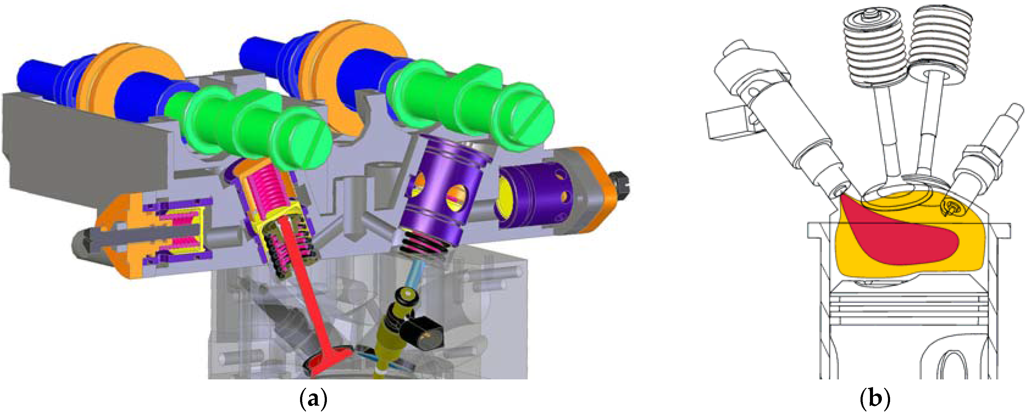
The experiments were performed on a test cell equipped with a SB 3.5 single-cylinder research engine mated to a direct current dynamometer at Lublin University of Technology. The engine’s geometric parameters are listed in Table 1. Due to the flexibility of the engine, all valvetrain parameters (valve timings and opening durations) could be changed independently during engine operation. A variable valvetrain was attained owing to a hydraulic device with manual control, shown in Figure 1a. The intake and exhaust valves were not directly actuated by the cams, rather using two pistons in a single cylinder. The space between the pistons was connected with a hydraulic accumulator cylinder. This cylinder was provided with a spring-supported control piston. The valve lift was controlled by adjusting position of the regulation screw, which limited the hydraulic accumulator’s volume. When the cam actuated the upper piston, oil filled the hydraulic accumulator until the accumulator piston reached the regulation screw. This is when the valve opening began. The described mechanism varied the valve lifts, changing an active range of the cam lifts. Valve timings were regulated by pivoting the timing belt sprockets on the camshafts.
Fuel was delivered directly to the cylinder with the use of a single-stream swirl-type injector. The location of the injector is shown in Figure 1b. The intake pressure was elevated using a vane compressor with an air cooling system. The compressor was driven by an electric motor, where pressure was controlled by both, compressor rotational speed and opening of a by-pass valve.
The engine test bench was equipped with all the necessary measurement and control instrumentation. The control system was based on a microprocessor timing module controlled by a personal computer with a real-time software for controlling injection timings and durations, and spark generation. All synchronization procedures (injection and ignition timing) were realized based on signals from a crankshaft encoder with an angular resolution of 0.1° in the domain of crank angle (CA). The in-cylinder pressure was recorded with the same resolution. An AVL GH 12D piezoelectric pressure transducer (AVL List GmbH, Graz, Austria) was installed directly in the engine head. Measurement signal was conditioned by a charge amplifier from the same manufacturer.
Exhaust gas compositions were measured by means of an AVL Sesam Fourier transform infrared (FTIR) multi-compound analytical system (AVL List GmbH, Graz, Austria). The measurement error in case of hydrocarbons was up to 0.49%, over concentration span from 0 to 1000 ppm. The measurement error of CO was 0.31% from 0 to 4000 ppm, whereas for NOX, an average error was 0.36% in the range from 0 to 10,000 ppm. Soot emissions were measured using a MAHA MPM4 analyzer (MAHA Maschinenbau Haldenwang GmbH & Co. KG, Haldenwang, Germany,), with the accuracy of 0.1 mg/m3. Additionally, a Bosch LSU 4.2 wideband oxygen sensor (Robert Bosch GmbH, Gerlingen, Germany) located in the exhaust runner and an Etas LA4 lambda meter (ETAS Ltd., Stuttgart, Germany) were used for the estimation of an overall main event excess air ratio. The intake air mass flow was measured by means of a thermal anemometer. Fuel consumption was measured by a fuel balance with constant measurement time of 30 s. The thermodynamic parameters of intake and exhaust were measured by a set of temperature and pressure transducers.
2.2. Experimental Conditions and Procedure
All data were collected at the engine speed of 1500 rev/min. The intake temperature was maintained at 50 °C ± 2 °C. The temperature of the cooling liquid at the engine outlet was maintained constant at 90 °C ± 1 °C. The engine was fueled with Euro Super commercial gasoline, with a research octane number (RON) of 95, from a single batch. The experiments were performed with the spark ignition system switched off.
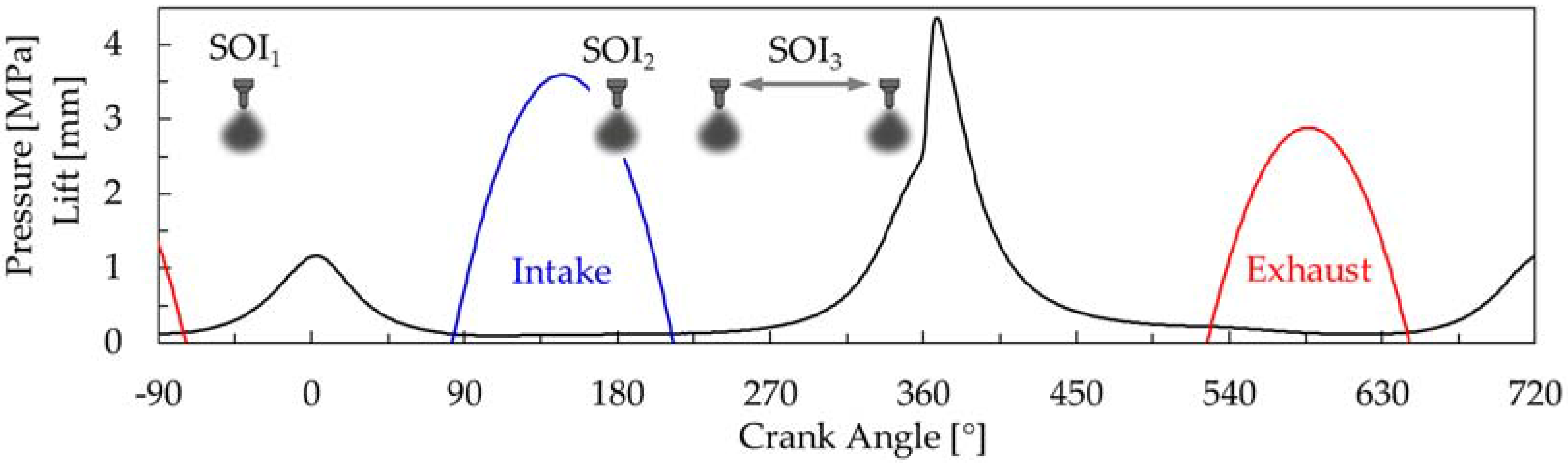
The tests were performed at constant valve lifts and timings. The opening phase of the intake valve (IVO) was 83° and the closing phase of the intake valve (IVC) was 213° with the lift of 3.6 mm. The opening phase of the exhaust valve (EVO) was 527° and the closing of the exhaust valve (EVC) was 646° with the lift of 2.9 mm. The valve lift profiles are shown in Figure 2. All experiments were performed at constant fuel mass (approximately 14 mg) delivered to the cylinder per single cycle. To enable a variable degree of fuel stratification, the following fuel injection scheme was applied. Fuel delivered to the combustion chamber was divided into three doses injected with selected start of injection (SOI) timings, shown in Figure 2. The timing of the first fuel dose SOI1 was fixed to −40 ° (40° before top dead center during NVO). The mass of fuel injected at SOI1 was fixed for all experiments to 2.6 mg. This was necessary to enable autonomous engine operation at variable boost pressures. After early fuel injection, fuel was partially burn during the NVO period. The heat released during this period compensated for the decrease in temperature resulting from an additional air delivered by boost. The second portion of fuel was injected at SOI2 = 180°. The timing of the third injection SOI3 varied from 240° to 340° to provide a variable degree of fuel stratification. The experiments were performed at two 3rd injection fuel doses: 2.4 mg and 5.2 mg. The remaining amount of fuel was delivered to the cylinder by 2nd fuel injection. All the experiments were repeated for two global mixture strengths expressed by the excess air ratio (λ) set to 1.3 and 1.6 and kept at the desired level by boost pressure. The required boost pressure was approximately 1.29 bar abs. for λ = 1.3, and 1.59 bar for λ = 1.6. The idea of mixture stratification and the employed combustion system are shown in Figure 1b. The area in yellow stands for a premixed mixture created with fuel injected in the 1st and 2nd injection, whereas the red area marks a higher fuel concentration prior to auto-ignition. Obviously, the later the 3rd injection occurs and the more fuel is injected, the more concentrated fuel can be observed in the red colored area in Figure 1b. This area has a lower air excess and a lower temperature because the heat of fuel vaporization is consumed from a limited volume.
2.3. Data Analysis
A detailed combustion analysis was performed on the basis of the recorded in-cylinder pressure traces using the AVL BOOST software (AVL List GmbH, Graz, Austria). The net indicated thermodynamic work of the engine cycle was calculated according to the following formula:
where p is in-cylinder pressure, and V is the volume above the piston. To compensate for energy consumption by external compressor, thermodynamic work of adiabatic air compression Wc was considered in calculations, as shown in (1). The net indicated mean effective pressure (IMEP) was calculated as a fraction of Wi and engine displaced volume. The engine thermal efficiency was calculated as a fraction of Wi and the amount of chemical energy introduced with the fuel, i.e., the mass of fuel multiplied by its lower heating value.
Combustion was analyzed using the HRR curves calculated on the basis of the first law of thermodynamics in the following form:
where γ is the specific heat ratio, calculated with consideration of the instantaneous temperature and mixture composition. The mass-averaged in-cylinder temperature was calculated using the gas equation of state, based on the volume, measured pressure and calculated in-cylinder mass, which consisted of mass of fuel, aspirated air and trapped residuals. The mass of the trapped residuals was also calculated using the gas equation of state, based on the volume, in-cylinder pressure and exhaust temperature at the EVC event.
The start of combustion (SOC) advance was expressed as the location of 5% mass fraction burned (MFB) of fuel, computed as a ratio of cumulative heat release to total heat release. Combustion duration was defined as the angular distance between 5% and 95% of MFB. Exhaust emissions were described as the indicated specific values, i.e., the mass of component related to indicated work.
3. Results and Discussion
3.1. Combustion Parameters
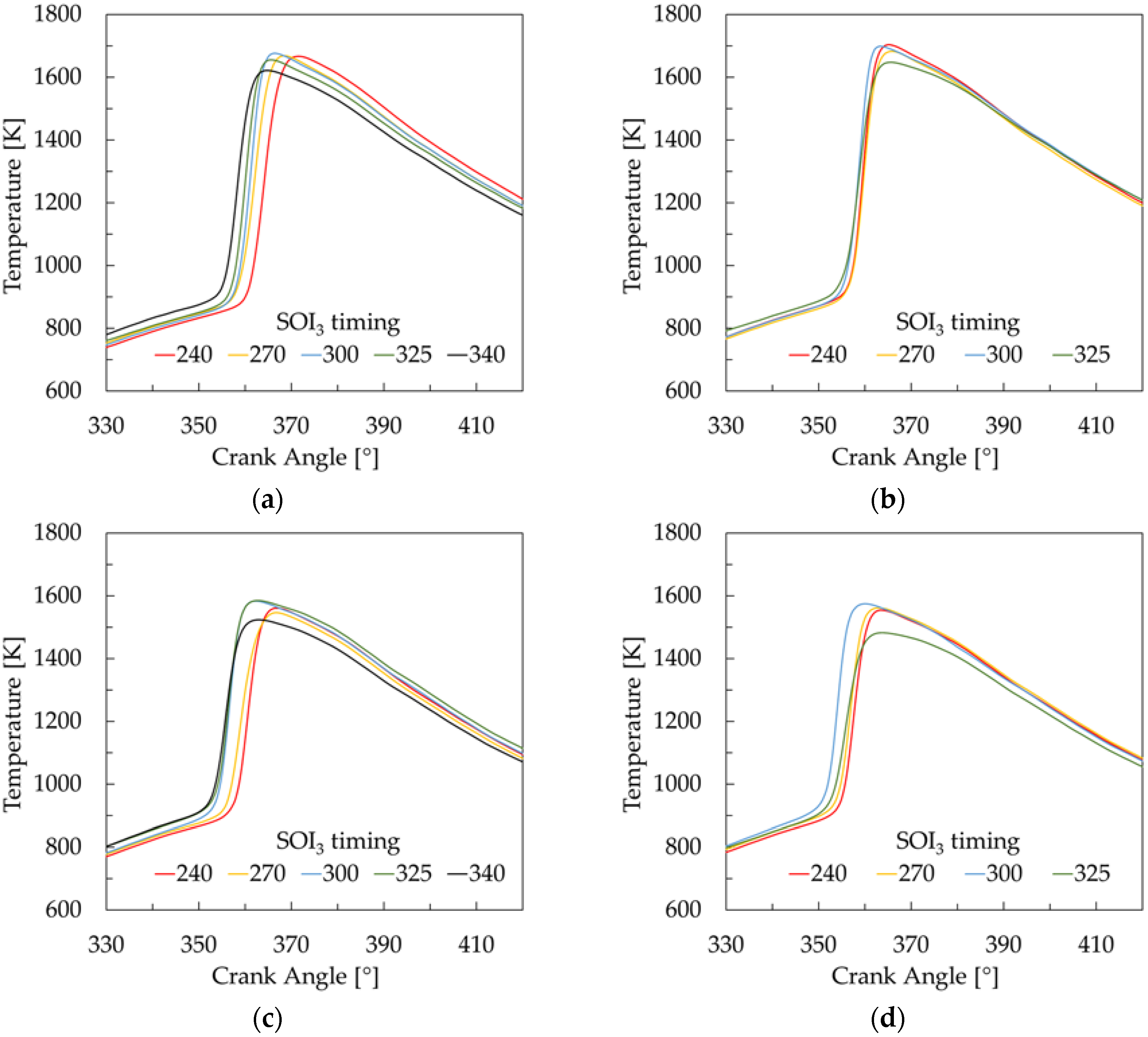
The traces of in-cylinder pressure during the main event for all investigated conditions are shown in Figure 3. The results demonstrate that SOI3 has a significant impact on combustion, which can be observed without any detailed thermodynamic analysis. In general, the later the injection is, the earlier the combustion starts. This is plausible, as the stratification creates fuel-rich regions characterized by lower temperature because of heat consumption for the fuel phase change. At the same time, the temperature in other regions increases, and these regions can ignite first. It should be noted however that there is no straightforward effect of stratification on combustion timing. A comparison of Figure 3a,b indicates that a higher stratification degree achieved for a larger mF3 has a less significant effect on combustion timing than lower stratification for a smaller mF3. At λ = 1.6, also for a larger mF3, the behavior of combustion timing is less predictable, as shown in Figure 3d. The in-cylinder temperature curves shown in Figure 4 demonstrate that the employed injection strategies exert impact on average temperature. Most temperature traces follow the following pattern: the higher the average temperature at the end of compression is, the earlier the start of combustion occurs.
More detailed data on combustion evolution is provided by the HRR curves, shown in Figure 5. It can be noted that the investigated injection strategies affect not only the SOC timing, but also the combustion duration. In all cases, the highest peak HRR values are observed for a moderate start of injection (SOI3 ≈ 300°). The observed non-linear effect of fuel stratification on combustion rate can be attributed to complex interactions associated with local mixture composition and local temperature. When the degree of fuel stratification increases, the hot spots in the combustion chamber advance auto-ignition [23,24]. The appearance of regions with high temperature and favorable excess air ratio creates conditions for the earliest auto-ignition and quick combustion.
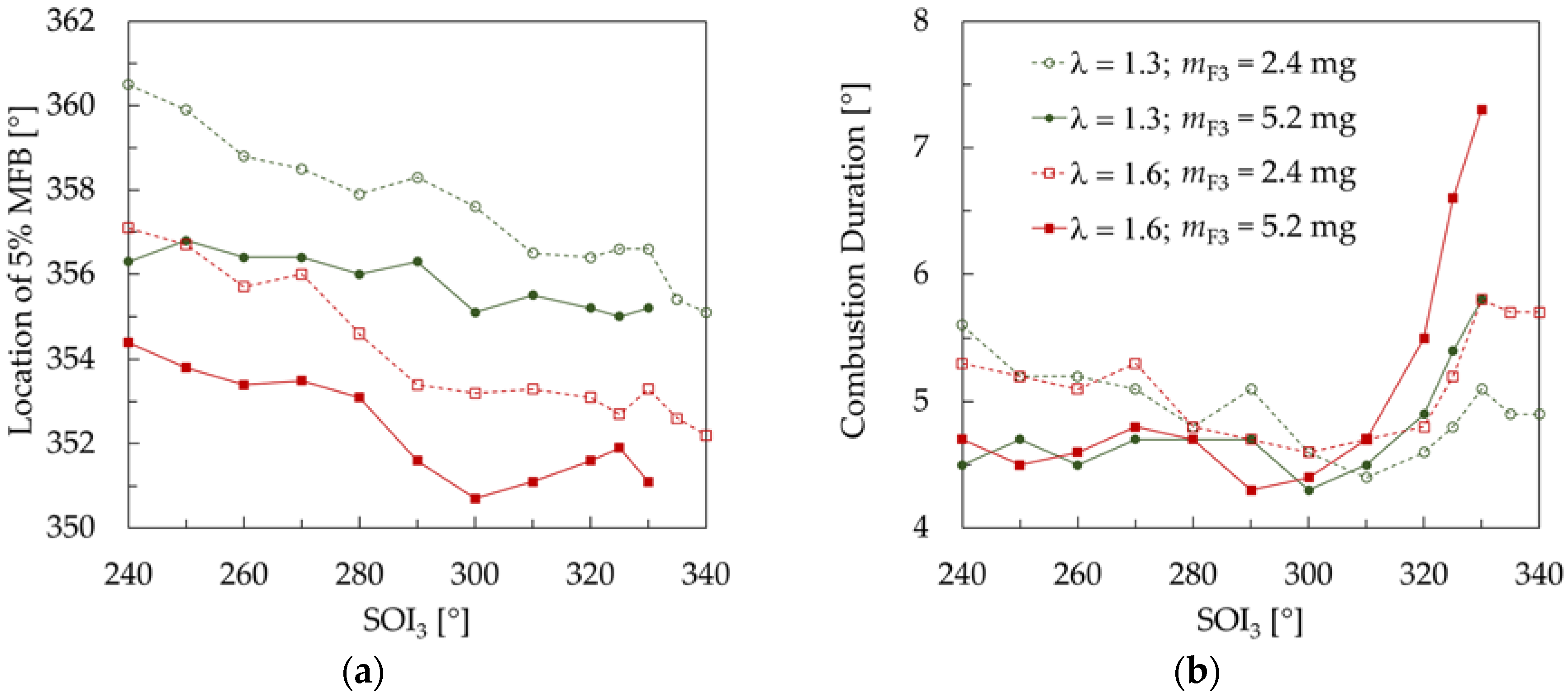
The trends in SOC expressed by 5% MFB and combustion duration for all investigated conditions are shown in Figure 6. Both the delay of SOI3 and the increase in the 3rd injection fuel lead to an advanced SOC. Additionally, a higher global excess air advances combustion, besides the mixture’s lower susceptibility to auto-ignition. The reason for this behavior is the heat release during the NVO period. At leaner mixture, the oxygen content in trapped residuals is higher, thus the amount of heat released during NVO is greater. Additionally, the NVO exhaust-fuel reactions produce auto-ignition promoting species that advance the start of combustion [30,31]. Figure 6b shows that the behavior of combustion duration differs from that of combustion timing. At early SOI3 (up to approximately 280°), the combustion duration is independent of excess air. At SOI3 from 240° to 280° the combustion duration is maintained constant for mF3 = 5.2 mg. The reduction of mF3 prolongs the combustion by approximately 1°, however solely for early SOI3. At SOI3 ≈ 300° the combustion duration is the same for all investigated conditions. A further delay of SOI3 prolongs the combustion process. At delayed SOI3, the following tendency can be observed: the more fuel is injected later and the higher the excess air is, the longer the combustion process takes. Thus, the same combustion durations are achieved for the cases when λ = 1.3, mF3 = 5.2 mg and λ = 1.6, mF3 = 2.4 mg. The introduction of a higher fuel dose at a very late SOI3 was limited by piston wetting and diffusion flame, resulting in a dramatic increase in the CO, unburned hydrocarbons (HC) and soot emissions, as discussed later in Section 3.2. However, for mF3 = 2.4 mg, the delay of SOI3 beyond 330° leads to an advanced SOC and reduced combustion duration, as shown in Figure 6.
One of the obstacles to high load operation of the CAI engine are excessive values of the PRR. Trends in the PRR for all investigated conditions are shown in Figure 7. Considering the fact that with a constant amount of energy released in the cylinder the PRR results solely from combustion timing and its duration, the data shown in Figure 7 are a straightforward consequence of the combustion evolution analyzed above. At early SOI3, the lowest PRR is achieved for a lower λ and a lower mF3. However, the PRR increases with delaying the SOI3 until approximately 310°. Similar trends can be observed in other investigated cases. For SOI3 delayed to above 300–310°, the PRR drops for all investigated conditions, where the effectiveness of the PRR reduction is higher for a larger mF3.
3.2. Exhaust Emissions
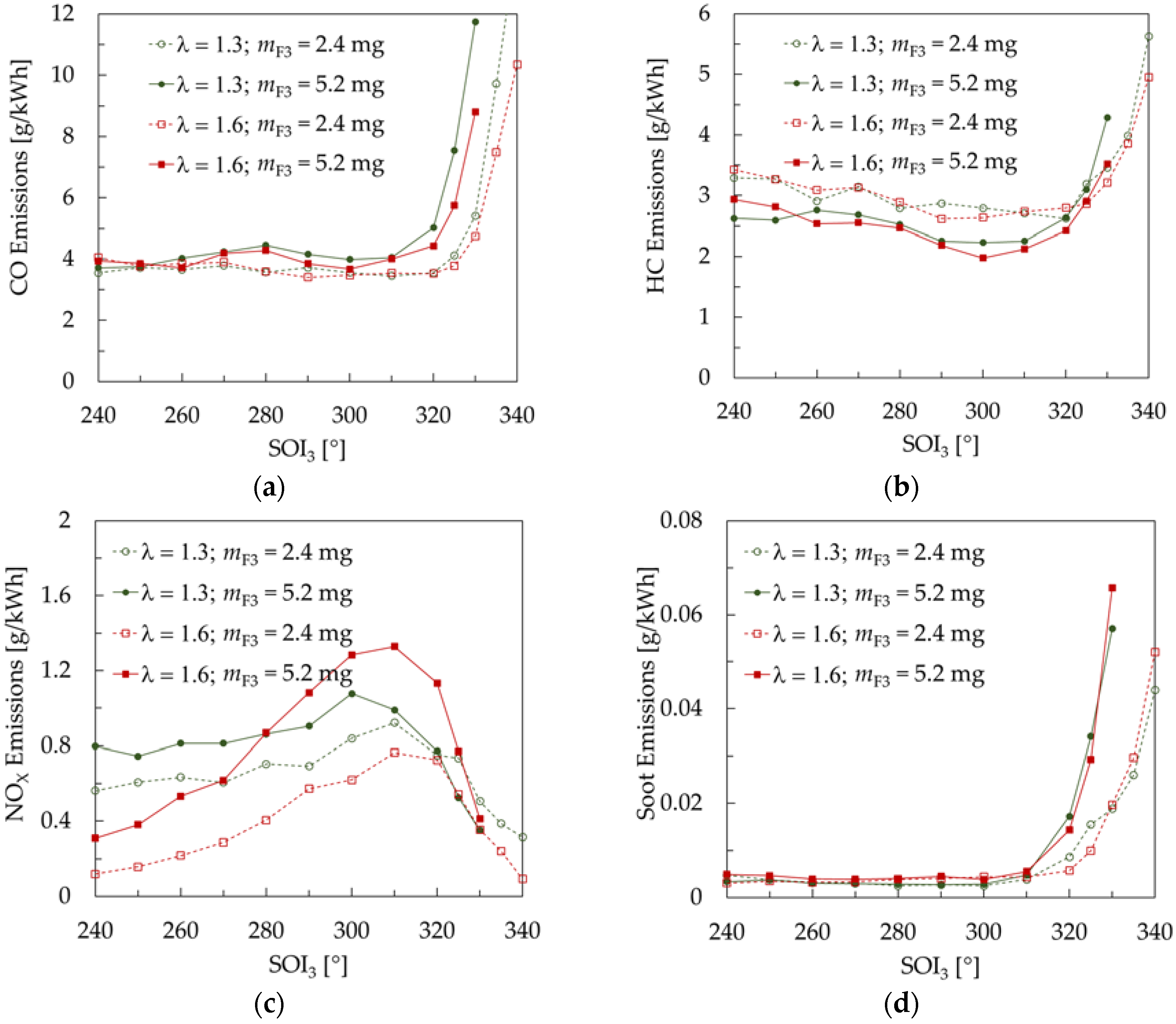
The techniques applied to control the combustion evolution are limited by excessive exhaust emissions. Figure 8 shows the indicated specific emissions of the main exhaust toxic compounds for all investigated conditions. It can be noted in Figure 8a that for early SOI3, up to approximately 320°, the emission of CO is almost independent of all control variables. In the above range of SOI3 there is a small reduction in the HC emissions for a larger mF3. The delay of SOI3 leads to reduced HC emissions. However, at SOI3 delayed beyond 320°, there is a dramatic increase in both the CO and HC emissions. This probably results from piston wetting and stratified combustion combined with the presence of oxygen-deficient regions.
Besides their negative effect on thermal efficiency, the increased CO and HC emissions do not pose a problem because they can be removed with the use of oxidation catalytic converters [32]. In contrast, the soot and NOX emissions are much more challenging, as their reduction requires the use of sophisticated exhaust after-treatment systems. It should be stressed that the main advantage of gasoline CAI combustion are the low soot and NOX emissions.
Figure 8c clearly demonstrates that, up to some level, the mixture stratification increases the NOX emissions. This effect is higher for λ = 1.6 and lower for λ = 1.3. The delay of SOI3 beyond 310° reduces the NOX emissions for all cases, however only for λ = 1.3 the emissions are lower than the emissions for early SOI3.
One of the most critical limitations of the applicable level of fuel stratification concerns the PM emissions, shown in Figure 8d. It can be noted that CAI produces a smokeless exhaust gas until a threshold value of liquid fuel combustion or piston wetting, above which the PM emissions increase dramatically. Considering the Soot emission limit of 0.01 g/kWh, the latest applicable SOI3 is approximately 320° for mF3 = 2.4 mg and 310 ° for mF3 = 5.2 mg.
3.3. Thermal Efficiency
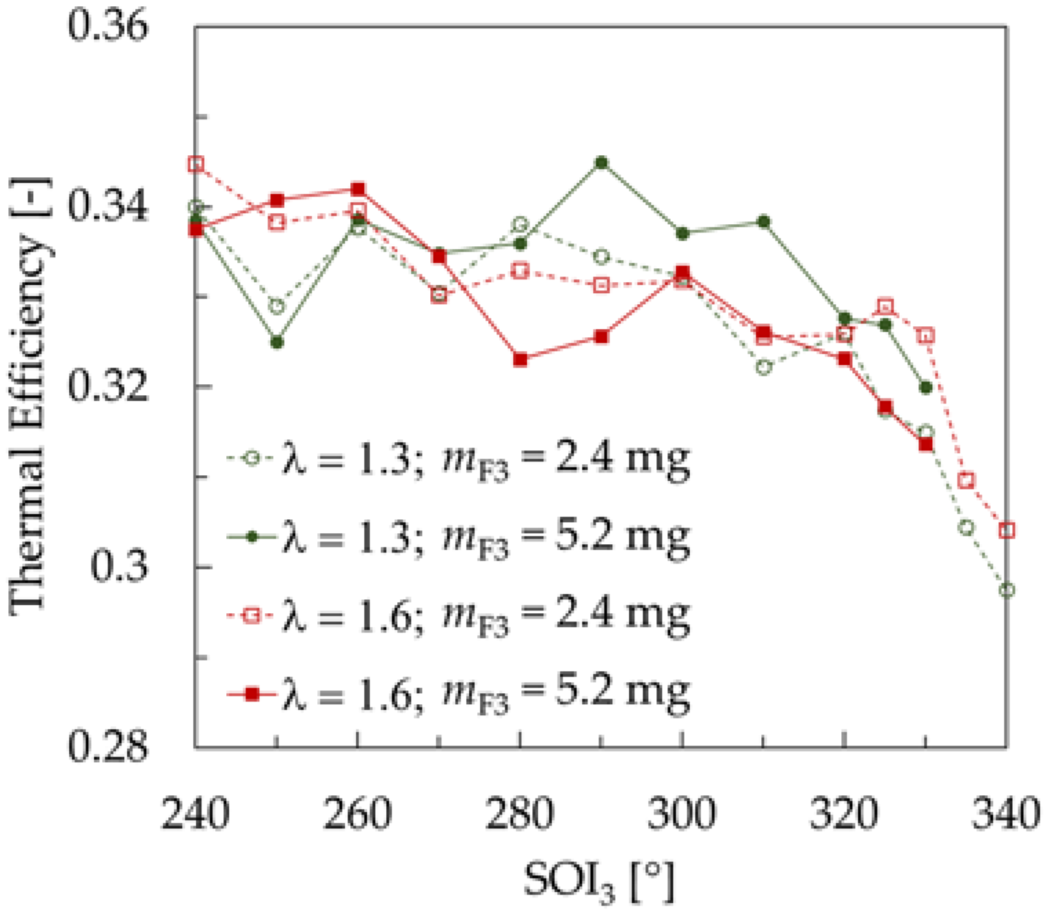
The trends in thermal efficiency shown in Figure 9 are the same for all four conditions. The observed values correspond to the net IMEP from 0.38 MPa to 0.44 MPa. It should be noted, however that the efficiency and the net IMEP were calculated with consideration of the thermodynamic work of adiabatic compression of the intake air. The delay in SOI3 leads to a gradual decrease in efficiency, because it is affected by the rise in emission of combustible species such as CO and HC. Additionally, it was shown earlier that the late injection advances the HRR, which further reduces cycle efficiency as combustion occurs before piston top dead center.
4. Conclusions
The present study investigated the influence of mixture stratification on the combustion, emissions and efficiency of a gasoline-fueled CAI engine. To induce CAI combustion, exhaust gas trapping by the NVO technique was applied. The engine was run at variable excess air ratio and variable direct fuel injection strategies to obtain different degrees of fuel stratification. The results have revealed the complex nature of the fuel stratification effects. The findings of this study are summarized below. The findings of this study are summarized below.
- The delay of fuel injection and the resulting increase in mixture stratification advance auto-ignition. Increasing the amount of fuel injected later for stratification also advances auto-ignition. Finally, the results demonstrate that auto-ignition also advances with increasing the excess air by the application of a higher boost pressure. The last effect is presumably a result of the NVO heat release, as some portion of fuel was injected during exhaust re-compression.
- The observed trend in combustion duration is much more complex than that in auto-ignition timing and reveals non-linear effects. The delay of fuel injection up to 300° does not affect the combustion duration to a high extent. A further delay of injection extends the combustion duration. The duration of the combustion process is prolonged by both the amount of fuel injected late and the global excess air ratio.
- Considering the above, fuel stratification could be effective in reducing the PRR provided that the end of compression temperature is reduced as well. This can be done by reducing the NVO fuel or the amount of trapped residuals.
- The emissions of CO, unburned HC and soot depend on the degree of mixture stratification. The delay of fuel injection beyond the threshold of 310–320° results in a dramatic increase in the emissions. This is presumably a result of piston wetting by the fuel stream.
- The emissions of NOX are substantially affected by fuel dilution. The increase in excess air reduces the emissions. With increasing the 3rd injection fuel dose the NOX emissions increase too, even for early injection. The maximum NOX emissions occur for the injection timing of 300–310°, where the highest peak HRRs are observed.
Acknowledgments
The research was funded by the National Science Centre, Poland under grant No. 2015/17/B/ST8/03279. The authors wish to thank AVL List GmbH for making simulation software available within a framework of AVL University Partnership Program. A. Tmar would like to thank J. Hunicz for the hospitality during his internship at the Lublin University of Technology.
Author Contributions
Jacek Hunicz and Paweł Krzaczek designed the experiments; Jacek Hunicz and Aymen Tmar performed the experiments; Aymen Tmar performed data processing (thermodynamic analysis etc.). Jacek Hunicz and Paweł Krzaczek analyzed the data and discussed the observed data trends. All authors contributed to writing the paper.
Conflicts of Interest
The authors declare no conflict of interest. The founding sponsors had no role in the design of the study; in the collection, analyses, or interpretation of data; in the writing of the manuscript, and in the decision to publish the results.
References
- Lavy, J.; Dabadie, J.; Angelberger, C.; Duret, P.; Willand, J.; Juretzka, A.; Schäflein, J.; Ma, T.; Lendresse, Y.; Satre, A.; et al. Innovative Ultra-Low NOx Controlled Auto-Ignition Combustion Process for Gasoline Engines: The 4-SPACE Project; SAE Technical Paper; No. 2000-01-1837; SAE International: Warrendale, PA, USA, 2000. [Google Scholar] [CrossRef]
- Zhao, H.; Li, J.; Ma, T.; Ladommatos, N. Performance and Analysis of a 4-Stroke Multi-Cylinder Gasoline Engine with CAI Combustion; SAE Technical Paper; No. 2002-01-0420; SAE International: Warrendale, PA, USA, 2002. [Google Scholar] [CrossRef]
- Yao, M.; Zheng, Z.; Liu, H. Progress and recent trends in homogeneous charge compression ignition (HCCI) engines. Prog. Energy Combust. Sci. 2009, 35, 398–437. [Google Scholar] [CrossRef]
- Shi, Y.; Reitz, R.D. Optimization of a heavy-duty compression-ignition engine fuelled with diesel and gasoline-like fuels. Fuel 2010, 89, 3416–3430. [Google Scholar] [CrossRef]
- Onishi, S.; Jo, S.H.; Shoda, K.; Jo, P.D.; Katao, S. Active Thermo-Atmosphere Combustion (ATAC)—A New Combustion Process for Internal Combustion Engines; SAE Technical Paper; No. 790501; SAE International: Warrendale, PA, USA, 1979. [Google Scholar] [CrossRef]
- Noguchi, M.; Tanaka, Y.; Tanaka, T.; Takeuchi, Y. A Study on Gasoline Engine Combustion by Observation of Intermediate Reactive Products During Combustion; SAE Technical Paper; No. 790840; SAE International: Warrendale, PA, USA, 1979. [Google Scholar] [CrossRef]
- Najt, P.; Foster, D. Compression-Ignited Homogeneous Charge Combustion; SAE Technical Paper; No. 830264; SAE International: Warrendale, PA, USA, 1983. [Google Scholar] [CrossRef]
- Hunicz, J.; Krzaczek, P. Detailed speciation of emissions from low temperature combustion in a gasoline HCCI engine. Pol. J. Environ. Stud. 2016, 25, 137–145. [Google Scholar] [CrossRef]
- Hasan, M.M.; Rahman, M.M.; Kadirgama, K.; Ramasamy, D. Numerical study of engine parameters on combustion and performance characteristics in an n-heptane fueled HCCI engine. Appl. Therm. Eng. 2018, 128, 1464–1475. [Google Scholar] [CrossRef]
- Bansal, G.; Mascarenhas, A.; Chen, J.H. Direct numerical simulations of autoignition in stratified dimethyl-ether (DME)/air turbulent mixtures. Combust. Flame 2015, 162, 688–702. [Google Scholar] [CrossRef]
- Huang, Z.; Li, Z.; Zhang, J.; Lu, X.; Fang, J.; Han, D. Active fuel design—A way to manage the right fuel for HCCI engines. Front. Energy 2016, 10, 14–28. [Google Scholar] [CrossRef]
- Turkcan, A.; Ozsezen, A.N.; Canakci, M. Effects of second injection timing on combustion characteristics of a two stage direct injection gasoline–alcohol HCCI engine. Fuel 2013, 111, 30–39. [Google Scholar] [CrossRef]
- Cairns, A.; Blaxill, H. The Effects of Combined Internal and External Exhaust Gas Recirculation on Gasoline Controlled Auto-Ignition; SAE Technical Paper; No. 2005-01-0133; SAE International: Warrendale, PA, USA, 2005. [Google Scholar] [CrossRef]
- Kulzer, A.; Lejsek, D.; Nier, T. A thermodynamic study on boosted HCCI: Motivation, analysis and potential. SAE Int. J. Engines 2010, 3, 733–749. [Google Scholar] [CrossRef]
- Dec, J.E.; Yang, Y. Boosted HCCI for high power without engine knock and with ultra-low NOX emissions—Using conventional gasoline. SAE Int. J. Engines 2010, 3, 750–767. [Google Scholar] [CrossRef]
- Saxena, S.; Bedoya, I.D. Fundamental phenomena affecting low temperature combustion and HCCI engines, high load limits and strategies for extending these limits. Prog. Energy Combust. Sci. 2013, 39, 457–488. [Google Scholar] [CrossRef]
- Lee, K.; Cho, S.; Kim, N.; Min, K. A study on combustion control and operating range expansion of gasoline HCCI. Energy 2015, 91, 1038–1048. [Google Scholar] [CrossRef]
- Hunicz, J.; Geca, M.S.; Kordos, P.; Komsta, H. An experimental study on a boosted gasoline HCCI engine under different direct fuel injection strategies. Exp. Therm. Fluid Sci. 2015, 62, 151–163. [Google Scholar] [CrossRef]
- Sjöberg, M.; Dec, J.E.; Cernansky, N. Potential of Thermal Stratification and Combustion Retard for Reducing Pressure-Rise Rates in HCCI Engines, Based on Multi-Zone Modeling and Experiments; SAE Technical Paper; No. 2005-01-0113; SAE International: Warrendale, PA, USA, 2005. [Google Scholar] [CrossRef]
- Rothamer, D.A.; Snyder, J.A.; Hanson, R.K.; Steeper, R.; Fitzgerald, R.P. Simultaneous imaging of exhaust gas residuals and temperature during HCCI combustion. Proc. Combust. Inst. 2009, 32, 2869–2876. [Google Scholar] [CrossRef]
- Dec, J.E.; Yang, Y.; Dronniou, N. Boosted HCCI—Controlling pressure-rise rates for performance improvements using partial fuel stratification with conventional gasoline. SAE Int. J. Engines 2011, 4, 1169–1189. [Google Scholar] [CrossRef]
- Yang, D.-B.; Wang, Z.; Wang, J.X.; Shuai, S.-J. Experimental study of fuel stratification for HCCI high load extension. Appl. Energy 2011, 88, 2949–2954. [Google Scholar] [CrossRef]
- Lim, O.T.; Iida, N. The investigation about the effects of thermal stratification in combustion chamber on HCCI combustion fueled with DME/n-Butane using Rapid Compression Machine. Exp. Therm. Fluid Sci. 2012, 39, 123–133. [Google Scholar] [CrossRef]
- Lim, O.T. Investigation of thermal stratification effect on n-Heptane/iso-Octane-Air mixture HCCI combustion. Int. J. Automot. Technol. 2013, 14, 843–855. [Google Scholar] [CrossRef]
- Kwon, O.S.; Lim, O. Effect of boost pressure on thermal stratification in HCCI engine using the multi-zone model. J. Mech. Sci. Technol. 2010, 24, 399–406. [Google Scholar] [CrossRef]
- Kodavasal, J.; Lavoie, G.A.; Assanis, D.N.; Martz, J.B. The effect of diluent composition on homogeneous charge compression ignition auto-ignition and combustion duration. Proc. Combust. Inst. 2015, 35, 3019–3026. [Google Scholar] [CrossRef]
- Lawler, B.; Mamalis, S.; Joshi, S.; Lacey, J.; Guralp, O.; Najt, P.; Filipi, Z. Understanding the effect of operating conditions on thermal stratification and heat release in a homogeneous charge compression ignition engine. Appl. Therm. Eng. 2017, 112, 392–402. [Google Scholar] [CrossRef]
- Li, N.; Xie, H.; Chen, T.; Li, L.; Zhao, H. The effects of intake backflow on in-cylinder situation and auto ignition in a gasoline controlled auto ignition engine. Appl. Energy 2013, 101, 756–764. [Google Scholar] [CrossRef]
- Thongchai, S.; Lim, O. Influence of injection strategy on a compression ignition engine fueled with gasoline. Energy Procedia 2017, 105, 1757–1763. [Google Scholar] [CrossRef]
- Peterson, B.; Ekoto, I.; Northrop, W. Investigation of negative valve overlap reforming products using gas sampling and single-zone modeling. SAE Int. J. Engines 2015, 8, 747–757. [Google Scholar] [CrossRef]
- Hunicz, J. An experimental study into the chemical effects of direct gasoline injection into retained residuals in a homogeneous charge compression ignition engine. Int. J. Engine Res. 2016, 11, 1031–1044. [Google Scholar] [CrossRef]
- Hunicz, J.; Medina, A. Experimental study on detailed emissions speciation of an HCCI engine equipped with a three-way catalytic converter. Energy 2016, 117, 388–397. [Google Scholar] [CrossRef]
Figure 1.
Cross-section of the valvetrain (a) and combustion system with mixture stratification idea (b).
Figure 1.
Cross-section of the valvetrain (a) and combustion system with mixture stratification idea (b).

Figure 2.
Example of in-cylinder pressure, profiles of valve lifts and injection timings.

Figure 3.
In-cylinder pressure: (a) λ = 1.3, mF3 = 2.4 mg; (b) λ = 1.3, mF3 = 5.2 mg; (c) λ = 1.6, mF3 = 2.4 mg; (d) λ = 1.6, mF3 = 5.2 mg.
Figure 3.
In-cylinder pressure: (a) λ = 1.3, mF3 = 2.4 mg; (b) λ = 1.3, mF3 = 5.2 mg; (c) λ = 1.6, mF3 = 2.4 mg; (d) λ = 1.6, mF3 = 5.2 mg.
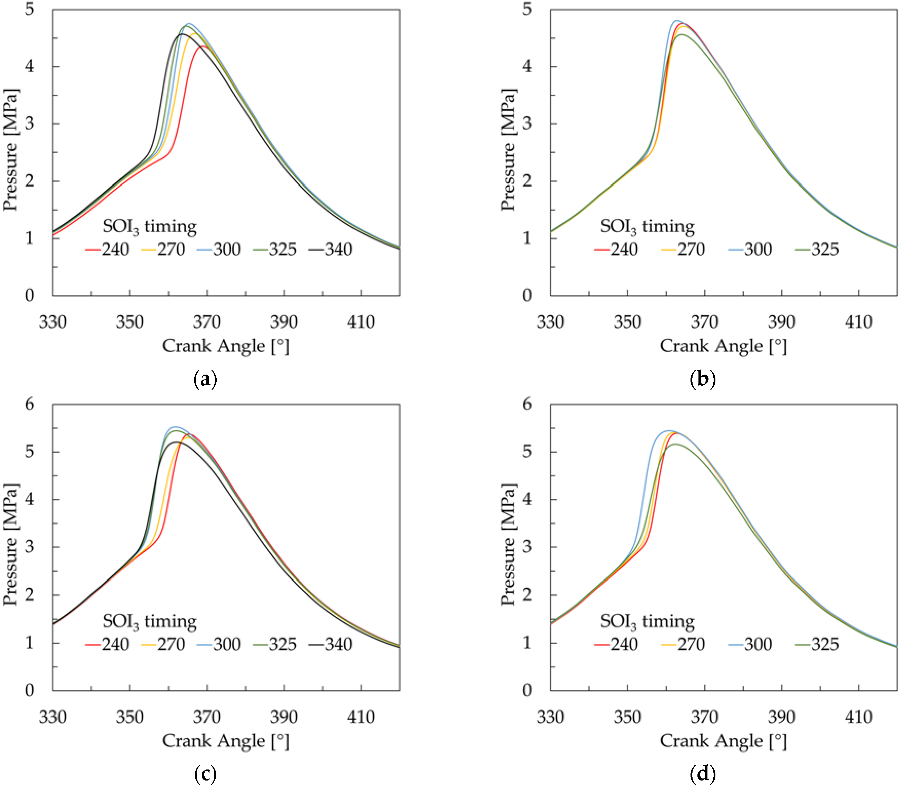
Figure 4.
Calculated in-cylinder temperature: (a) λ = 1.3, mF3 = 2.4 mg; (b) λ = 1.3, mF3 = 5.2 mg; (c) λ = 1.6, mF3 = 2.4 mg; (d) λ = 1.6, mF3 = 5.2 mg.
Figure 4.
Calculated in-cylinder temperature: (a) λ = 1.3, mF3 = 2.4 mg; (b) λ = 1.3, mF3 = 5.2 mg; (c) λ = 1.6, mF3 = 2.4 mg; (d) λ = 1.6, mF3 = 5.2 mg.

Figure 5.
Calculated heat release rate: (a) λ = 1.3, mF3 = 2.4 mg; (b) λ = 1.3, mF3 = 5.2 mg; (c) λ = 1.6, mF3 = 2.4 mg; (d) λ = 1.6, mF3 = 5.2 mg.
Figure 5.
Calculated heat release rate: (a) λ = 1.3, mF3 = 2.4 mg; (b) λ = 1.3, mF3 = 5.2 mg; (c) λ = 1.6, mF3 = 2.4 mg; (d) λ = 1.6, mF3 = 5.2 mg.
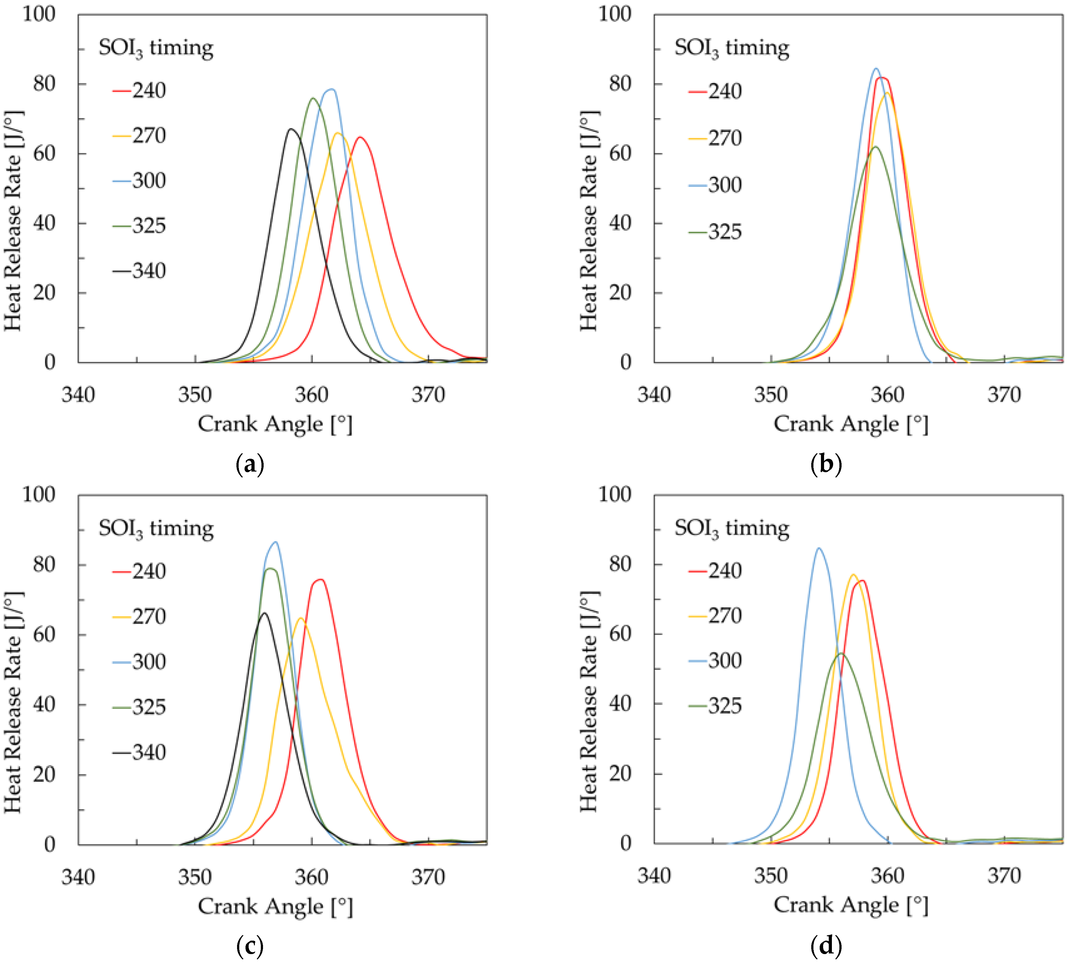
Figure 6.
Location of 5% mass fraction burned (MFB) (a) and combustion duration (5–95% MFB) (b) versus SOI3 timing for all investigated conditions.
Figure 6.
Location of 5% mass fraction burned (MFB) (a) and combustion duration (5–95% MFB) (b) versus SOI3 timing for all investigated conditions.

Figure 7.
Pressure rise rate versus SOI3 timing for all investigated conditions.
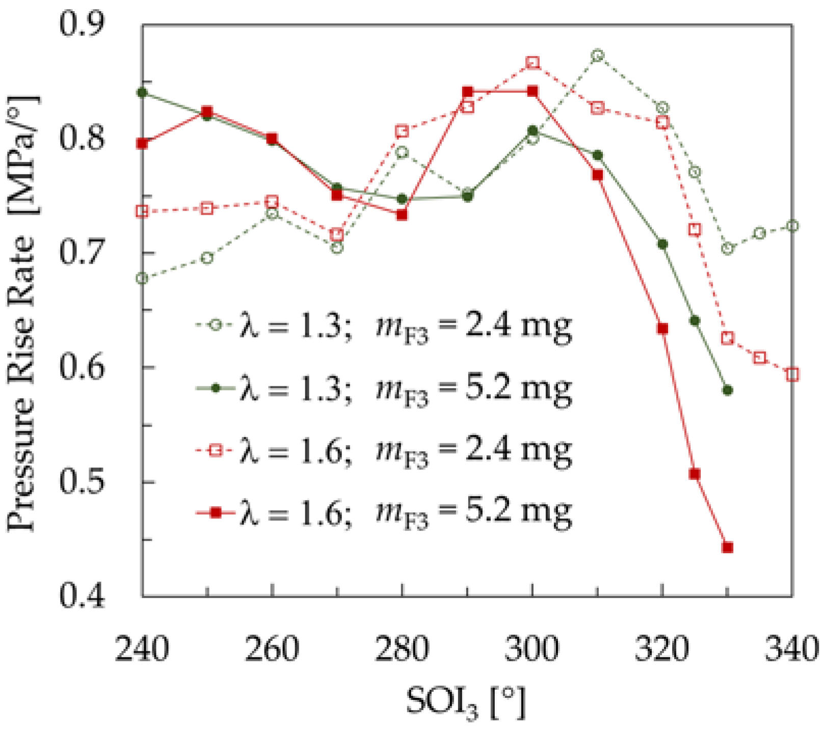
Figure 8.
Indicated specific emissions of exhaust toxic compounds versus SOI3 timing for all investigated conditions: (a) CO; (b) unburned hydrocarbons (HC); (c) NOX; (d) soot.
Figure 8.
Indicated specific emissions of exhaust toxic compounds versus SOI3 timing for all investigated conditions: (a) CO; (b) unburned hydrocarbons (HC); (c) NOX; (d) soot.

Figure 9.
Net indicated thermal efficiency versus SOI3 timing for all investigated conditions.

Table 1.
Research engine specifications.
| Parameter | Value |
|---|---|
| Displaced volume | 498.5 cm3 |
| Bore | 84 mm |
| Stroke | 90 mm |
| Compression ratio | 11.7 |
| Number of valves | 2 |
| Intake cam profile | 9.4 mm, 235 °C A |
| Intake valve lift | 2.4 ... 9.4 mm |
| Exhaust cam profile | 9.2 mm, 235 °C A |
| Exhaust valve lift | 2.2 ... 9.2 mm |
© 2017 by the authors. Licensee MDPI, Basel, Switzerland. This article is an open access article distributed under the terms and conditions of the Creative Commons Attribution (CC BY) license (http://creativecommons.org/licenses/by/4.0/).
Share and Cite
MDPI and ACS Style
Hunicz, J.; Tmar, A.; Krzaczek, P. Effects of Mixture Stratification on Combustion and Emissions of Boosted Controlled Auto-Ignition Engines. Energies 2017, 10, 2172. https://doi.org/10.3390/en10122172
AMA Style
Hunicz J, Tmar A, Krzaczek P. Effects of Mixture Stratification on Combustion and Emissions of Boosted Controlled Auto-Ignition Engines. Energies. 2017; 10(12):2172. https://doi.org/10.3390/en10122172
Chicago/Turabian StyleHunicz, Jacek, Aymen Tmar, and Paweł Krzaczek. 2017. "Effects of Mixture Stratification on Combustion and Emissions of Boosted Controlled Auto-Ignition Engines" Energies 10, no. 12: 2172. https://doi.org/10.3390/en10122172
Note that from the first issue of 2016, this journal uses article numbers instead of page numbers. See further details here.