Optimal Power Assignment of Energy Storage Systems to Improve the Energy Storage Efficiency for Frequency Regulation


1
Korea Electric Power Research Institute (KEPRI), Korea Electric Power Company (KEPCO), 105 Munji-Ro, Yuseong-gu, Daejeon 34056, Korea
2
Department of Electrical Engineering, Chonnam National University, 77 Yongbong-Ro, Buk-Gu, Gwangju 61186, Korea
*
Author to whom correspondence should be addressed.
Energies 2017, 10(12), 2092; https://doi.org/10.3390/en10122092
Submission received: 12 November 2017
/
Revised: 2 December 2017
/
Accepted: 5 December 2017
/
Published: 9 December 2017
(This article belongs to the Section D: Energy Storage and Application)
Abstract
:Losses in energy storage systems (ESSs) are considered operational costs and it is critical to improve efficiency in order to expand their use. We proposed a method of improving efficiency through the operation algorithm of an ESS, consisting of multiple energy storage units (ESUs). Since the ESS used for frequency adjustment maintains a fast response characteristics, we have created a lookup table of efficient ESU operating combinations using genetic algorithms in advance to maintain a fast response time. In addition, the charge/discharge energy balance between the plurality of ESUs is maintained, and the deterioration is prevented from being concentrated in some ESUs. The proposed algorithm was reviewed based on three case studies. The first case study examined whether the lookup table obtained using the genetic algorithm well identified the optimal solution. The second compared the system that optimally distributes the output to ESUs to achieve ESS efficiency for frequency regulation with the system that uniformly distributes the output to ESUs. The third analyzed the impact of efficiency enhancement on the operation of an ESS for frequency regulation through a one-month simulation. The findings confirmed that when the entire system output is optimally allocated to the ESUs, the system’s economic efficiency can be improved by reducing the loss while maintaining the accumulative charge/discharge balance.
1. Introduction
An energy storage system (ESS) is useful for enhancing the efficiency and economic feasibility of power systems. Recently, ESSs are increasingly used due to their technical development and reduced costs. In particular, ESSs are better at frequency regulation than existing steam-power generators owing to their rapid response speed.
In power systems, frequency is an index that represents the discrepancy between the power output and the load. If the load is greater than the output, the frequency is lower than the rated frequency. In contrast, when the load is smaller than the output, the frequency increases. Therefore, when the frequency increases, an ESS for frequency regulation performs the charging action to be operated as a load; however, when the frequency decreases, it performs the discharging action to be operated as a generator [1]. In general power systems, frequency regulation is performed by conventional generators, such as steam-power generators or Liquefied Natural Gas (LNG) generators. For a generator to regulate the frequency, it should constantly maintain an output lower than its maximum capacity so that it can increase its output when the frequency decreases. Therefore, the frequency regulation of a conventional generator is accompanied by constraint cost. Considering such limitations, ESSs for frequency regulation are feasible in the power market structure in Korea [2]. For this reason, the Korea Electric Power Company (KEPCO) is currently building a 500 MW ESS for frequency regulation.
Generally installed in a 24–48 MW unit at each site, ESSs for frequency regulation comprise multiple energy storage units (ESUs). Each ESU is connected to a common AC bus via an individual transformer. The AC bus is connected to a power grid via the main transformer. The ESS operation system at each site is required to control multiple ESUs [3]. In general, an ESS comprises a power conversion system (PCS), which converts the DC output to AC, and a storage medium, for example, a lithium or flow battery, which charges and discharges energy in DC output. This study solely considers the loss of the PCS as this loss is relatively larger than that of lithium batteries [4].
Previous research [5,6] proposed dividing multiple ESUs into two groups: one for discharging and the other for charging. This method prevents frequent switching of a lead acid battery from the charging mode to the discharging mode for the battery’s longer lifespan. However, since lithium-ion batteries and redox flow batteries are mainly used in ESSs for frequency regulation [7,8], the operational strategy for multiple ESUs that considers the characteristics of lead acid batteries is not adequate. Moreover, in a previous study [8], a distribution algorithm was proposed considering the variation in the state of charge (SOC). However, in an ESS comprising ESUs with identical characteristics, no significant variation exists among the units and the charging and discharging amounts of the ESUs is equal to the uniform distribution of the total charging and discharging amount of the ESS divided by the number of units. Since this algorithm only manages SOC and efficiency is not considered, we analyzed that it operates with low efficiency.
In this paper, we propose an algorithm to allocate the output of ESU to improve ESS efficiency. In addition, the proposed algorithm prevents the concentration of deterioration in some ESUs. The deterioration of the energy storage device based on the lithium battery proceeds as the charge/discharge operation is performed. Therefore, if some of the ESUs of the plurality of ESUs perform more charge/discharge operations than the other ESUs, the ESU is further degraded. An appropriate allocation of the charging and discharging amounts among the units is an important role of the operation system in many ESUs for preventing the partial deterioration of some units.
The power allocation techniques proposed in this paper can be applied to other energy storage technologies consisting of multiple ESUs such as flywheel and flow batteries [9,10].
The remainder of this paper organized as follows. Section 2 analyzes an ESS for frequency regulation and its operational history, Section 3 explains the operational strategy for efficiency enhancement, and Chapter 4 analyzes the impact of efficiency enhancement and operational history through a one-month simulation.
2. ESS for Frequency Regulation
Lithium-ion battery-based ESSs comprise multiple ESUs. A lithium battery cell usually has a voltage of 3.3–3.7 V. These cells are connected in parallel or in series to construct a battery system. The typical battery system has a DC voltage range of 750–1000V, which varies in accordance with the charged status, and is linked to a power system via a 1–2 MW PCS.
Figure 1 shows the general ESS structure of a typical 24 MW ESS for frequency regulation. An ESU linked to a 23 kV AC bus via an interconnection transformer. A single ESU comprises a 1 MW PCS and a 250 kWh battery, and a system comprises 24 ESUs connected to the AC bus in parallel. The ESS has a power management system (PMS) to control the 24 ESUs. The PMS exchanges information with the PCS inside the ESUs and the battery management system (BMS) installed in the battery.
The ESS for frequency regulation operated by the KEPCO has two operation modes: normal mode and transient mode [8,11,12,13]. The transient mode is used when the frequency dramatically decreases due to issues such as the tripping of the power generator, and the normal mode is used in other cases. Because it is rarely used, the transient mode does not require a large proportion of the operation time and does not have a significant impact on the improvement in the ESS operation efficiency. Therefore, this paper presents an algorithm for allocating the ESS output to each ESU in order to only improve the operational efficiency in the normal mode.
Figure 2 shows the frequency data of the power system of Korea measured for a month in January 2013. The frequency was mostly in the range 59.95–60.05 Hz [14].
As shown in Figure 3, the frequency regulation algorithm in the normal mode used by the KEPCO operates in accordance with the frequency and SOC.
The ESS for frequency regulation performs the charging and discharging operations to maintain the frequency at 60 Hz, with a frequency dead band of ±0.03 Hz. If the frequency is maintained within 59.97–60.03 ± 0.03 Hz (frequency dead band), the ESS operates to maintain the SOC at 65% and not to charge and discharge to maintain the frequency. Since the frequency can rise or fall, for frequency regulation, it is ideal for the ESS to always maintain the SOC at 50% in order to maintain its standby mode. However, as shown in Figure 2, the frequency is more prone to decrease than to increase; therefore, KEPCO uses a strategy to maintain the SOC at 65% ± 2%. If the SOC is between 63% and 67%, the ESS is in standby mode. If the SOC exceeds 67%, it discharges to 5% of the rated output. Furthermore, when the SOC is over 80%, it discharges to 10% of the rated output. In contrast, when the SOC is smaller than 63%, it charges to 5% of the rated output and to 10% when the SOC is 50% or less.
If the frequency is 60.03 Hz or above, the system is supposed to enter a charging mode, but it stays in the standby mode if the SOC is over 80%. Similarly, it should start discharging below the frequency of 59.97 Hz; however, it fails to perform this when the SOC is 50% or less. Droop control shares the same principles with frequency control of conventional generators [1]. The charging and discharging amounts in the droop control mode are determined by the following equation.
Here, Pess represents the charging and discharging amounts of the ESS in kW, while fbase refers to the nominal frequency of 60 Hz, where f is the measured frequency. K is the droop index, which is 0.279%. If the current frequency is 59.95 Hz, the system discharges 7160 kW (= (60−59.95)/60/0.00279 × 24,000).
Figure 4 shows the output of the 24 MW ESS for frequency regulation in accordance with the frequency shown in Figure 2. The ESS output was calculated every 4 s, with the algorithm constructed using MATLAB/Simulink, while ignoring the loss. Most output values fell between −6 and 6 MW. When the 6 MW output of the ESS was uniformly allocated to 24 ESUs, each unit was expected to produce an output of 250 kW (=6 MW/24).
Figure 5 indicates the operation efficiency and distribution derived from the operation data for one week. The efficiency data was measured at a lithium battery energy storage system installed at the Jochon substation in Jeju Island, Korea [4]. The histogram in Figure 5 shows the power output distribution of the ESU measured for one week at 4 s intervals. Approximately 75% of the operation showed an output of 50 kW. This is equivalent to 90% efficiency, which is significantly lower than the maximum efficiency of 97%. The 50 kW output distribution of the ESU is particularly high because when the charging and discharging operations are performed at 5% of the rated output to maintain the SOC level, 5% of the 24 MW ESS output is equal to 1.2 MW, which is uniformly distributed among the 24 units by 50 kW (=1200 kW/24). Most of the remaining ESUs generated less than 250 kW, resulting in a considerably low efficiency. Therefore, the uniform distribution of the ESS output to each ESU is highly inefficient as it produces a considerably low operational efficiency.
3. Optimal Power Assignment Algorithm
To enhance the efficiency of the ESS for frequency regulation, this paper presents an algorithm that adjusts the output allocated to the ESUs comprising the ESS. The ESS for frequency regulation is required to retain its rapid response. A lookup table was created before conducting the study in order to minimize the loss and optimize the ESU combination according to the ESS output. This table was created using a genetic algorithm. Once the lookup table was created, the ESUs were classified as those for operation and those for standby considering the cumulative charging and discharging amounts to maintain the deterioration balance.
3.1. Power Assignment Lookup Table Created Using a Genetic Algorithm
This study utilizes a lookup table to optimally allocate the output enhance the efficiency of the ESS comprising multiple ESUs. As the ESS for frequency regulation features a rapid response time, the predetermined lookup table was used to assure speedy calculation.
The lookup table for the efficiency enhancement of the ESS for frequency regulation consists of the number of ESUs to be operated in accordance with the ESS output and the output of each ESU. Here, the output of the ESU is defined in a percentage unit against the rated output to simplify the table to feature nothing other than integers. When a lookup table is created, a complicated combinatorial optimization problem arises as the number of ESUs increases and the combination of power allocation rises accordingly. For this reason, this study utilizes a genetic algorithm that is commonly used in combinatorial optimization to create the lookup table [15].
In the genetic algorithm, the structure of string chromosome is shown in 6. The length of the string corresponds to the number of ESUs, whereas each integer indicates each ESU output. The chromosome sequence in Figure 6 indicates the output of four ESUs, and the total output is 224%. If the rated output of the ESU is 1 MW, the chromosome sequence in Figure 6 describes that 2.24 MW was distributed into 0.8, 0.5, 0.5, and 0.44 MW, respectively.
Figure 7 shows a flow chart for finding the optimal combination of ESUs using genetic algorithms. For Genetic Algorithm (GA) application, the rated power of ESU, the number of ESU and the efficiency function of ESU are input. In this paper, PESU is 1 MW and NESU is 24. The lookup table finds the optimal efficiency combination while increasing the total power output of the ESS from 500 kW to its rated output. Generation of initial population was randomly generated and we generate 200 populations. Since the objective function of the genetic algorithm is loss minimization, the losses for each chromosome were calculated and the populations were sorted in ascending order of loss. In the sorting process, the chromosomes whose duplicate chromosomes and ESUs output sum do not equal the total output were deleted. If the convergence condition is not satisfied, a new chromosome group is generated by mutation calculation and the process returns to the step of calculating the loss again. If the convergence condition is satisfied, the next step is to generate a lookup table for the total power output. When the lookup table is completed up to the rated output of the ESS, the operation is terminated.
The lookup table assumes the case of charging to be the same as that of discharging. In addition, it assumes that the characteristics of multiple ESUs are identical, so the order of the chromosome sequence is not significant. The table was always filled in in a descending order from the left side.
The lookup table created using the genetic algorithm is shown in Table 1. Once the output of the ESS is calculated, the lookup table enables us to instantly identify the number of ESUs to be in operation and the output to allocate to each unit.
Figure 8 shows the comparison between the system efficiency of assigning the output optimally to the ESU by the lookup table and the system efficiency evenly assigned to the ESU. It can be observed that the efficiency levels are strikingly different below 50% of the rated output of 24 MW. In Figure 5, most actions of the ESS for frequency regulation yielded an output of 50% or less, so it is expected that the efficiency enhancement through optimal allocation using the genetic algorithm would have a dramatic effect.
3.2. ESU Selection According to the Historical Data
When the lookup table is created for the best efficient operation through the genetic algorithm, only some ESUs should be operated. Therefore, an algorithm for selecting the ESUs to be operated is required. This study utilizes an algorithm that selects ESUs in consideration of the cumulatively charged and discharged amounts to avoid deterioration unbalance of particular units. The deterioration of the energy storage device based on the lithium battery proceeds as the charge/discharge operation is performed. Therefore, if some of the ESUs of the plurality of ESUs perform more charge/discharge operations than the other ESUs, the ESU is further degraded. In this paper, the cumulative charge/discharge amount of the ESUs is managed at a similar level to prevent further deterioration of only some of the ESUs. Figure 9 shows an example of such an algorithm. Each unit logs the cumulatively charged and discharged energies at a fixed interval. The charging sequence is determined in an ascending order based on the cumulatively charged energy (CCE). Similarly, the discharging sequence is determined based on the cumulatively discharged energy (CDE). If three ESUs are required to discharge energy according to the lookup table, three units are selected based on the discharging sequence. The unit with a lower order is allocated more output. The ESUs to be charged are selected similarly.
4. Case Study
Herein, three case studies were conducted. The first case study was conducted to review the convergence of the genetic algorithm used to create the lookup table. The second case study simply applied the output of the ESS for frequency regulation to the operation distributed by the optimal efficiency and equally to the uniformly distributed operation and analyzed the difference of losses. In the comparison of the two operating strategies, we did not implement the frequency regulation algorithm and used the output of ESS shown in Figure 4. In Case Study 2, SOC change due to loss reduction through optimal operation can be confirmed.
The third case applied an algorithm for frequency regulation to two ESSs—one applied by the optimal allocation and the other applied by uniform distribution—and compared the results of their operations for one month. The frequency regulation algorithm performs charge/discharge operation to keep the SOC value within a certain range. Therefore, Case Study 2 shows only the difference of SOC change due to efficiency improvement, and Case Study 3 shows the change in charge/discharge operation due to the difference of SOC.
4.1. Case I: GA Convergence Test
Herein, the optimal output allocation of ESUs was summarized in the lookup table using the genetic algorithm for the efficiency enhancement of the operation. To confirm whether the lookup table created using the genetic algorithm appropriately identified the optimal solution, every combination of the ESS comprising four ESUs was analyzed and the results were compared with those obtained using the genetic algorithm.
Figure 10a shows the combinations of four 1 MW ESUs that yield an output of 1640 kW and the loss according to each combination. We have searched the ESU combination of all output combinations to 1640 kW, increasing by 10 kW. A total of 25,355 cases were analyzed, and the minimum loss was 47.24 kW. The results of the genetic algorithm (47.24 kW) are indicated by a red line in Figure 10b. The genetic algorithm was found to allocate outputs of 550, 550, and 540 kW to the three running ESUs, respectively. Here, the results of the genetic algorithm showed the same value as the minimum loss obtained by exploring the entire combinations. Therefore, the analysis described in Figure 10 shows that the genetic algorithm well identifies the points of optimal operation.
4.2. Case II: Simple Loss Decrease Test
The second case study compared the losses from the uniform allocation algorithm and optimal efficiency algorithm. The 24 MW ESS model with 24 1 MW ESUs (Figure 1) was used. Table 2 summarizes the results of applying the output allocation algorithms of each ESU to the charging and discharging actions of the ESS for frequency regulation for one day. The total energy charged for one day was 14.29 MWh, whereas the total discharged energy was 14.51 MWh. The SOC at the beginning of the operation was 65%. It was confirmed that the operation with optimal allocation reduced the loss by 1654 kWh.
Figure 11 shows the change in the SOC according to the output allocation algorithms among units when operating the ESS for frequency regulation for 24 h. When the output of the ESS was fixed, the SOC further decreased during uniform allocation due to the difference of losses depending on the allocation method for the units.
Figure 12 describes the operational distribution and efficiency points of the ESU1 for 24 h. The individual units operated with a high efficiency between 500 and 600 kW. When compared with the operation distribution and efficiency of the ESU in a uniformly allocated operation (Figure 5), the enhancement in the optimal operation efficiency can be observed.
Figure 13 shows the distribution of the cumulative energy discharged by the ESU for 1, 6, 12 and 24 h. The variation of the discharged energy among the ESUs gradually decreased as the operation time increased. When the 24 EUSs are discharged uniformly, the distribution rate of the individual units was 4.166% (=1/24 × 100). After 24 h of operation, the variation among the units was found to be similar with the results of applying the uniformly allocated output of the units. Therefore, it is possible to improve the system efficiency while reducing the variation of operation history among units to prevent the concentrated deterioration of particular units.
4.3. Case III: Effect of Losses on the Frequency Regulation Operation
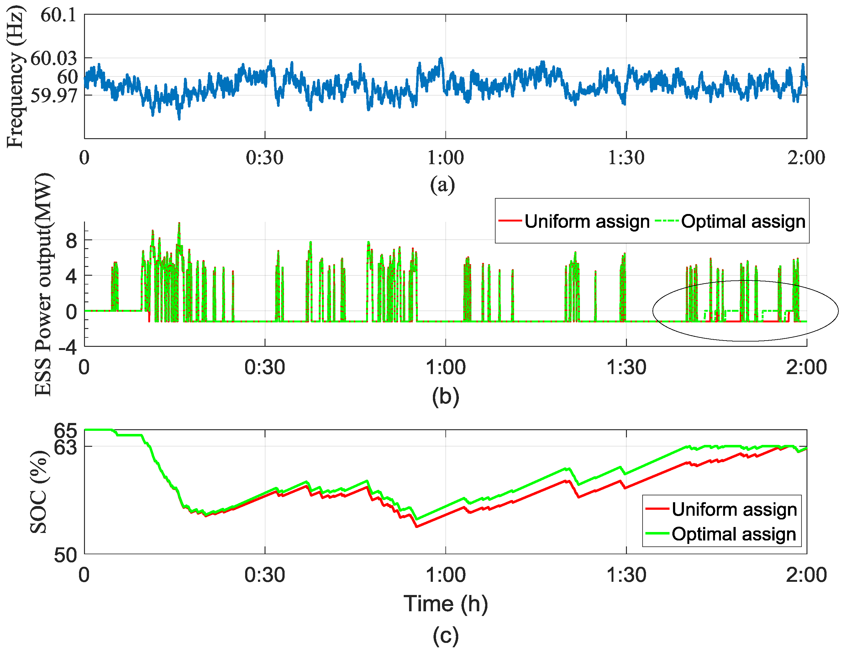
An ESS should maintain its SOC level at approximately 65% to prepare for charging when the frequency rises and for discharging when the frequency falls. When the frequency is within the allowable range, the system either charges or discharges energy to maintain the SOC at 65%. As analyzed above, the reduced loss decreases the SOC variation, so the frequency of the charging and discharging operations can be reduced to maintain the SOC within 63–67%. As shown in Figure 2, this case study applied the frequency for one month and the algorithm of the ESS for frequency regulation to calculate the charged and discharged energy and compared the results of the operations with uniform allocation and optimal allocation of the output of the ESU. Figure 14 shows a detailed description of two hours of the one-month operation.
In Figure 14a, when the frequency exceeds the dead zone (59.97–60.03 Hz), the system either charges or discharges energy to maintain the appropriate frequency. When the frequency is within the dead zone, the system charges or discharges energy in order to maintain the SOC between 63% and 67%. If the frequency falls below 59.97 Hz, the 24 MW ESS discharges energy, the amount of which is calculated in Equation (1). Here, if the output is uniformly distributed, the loss is greater than optimal distribution using the lookup table and the SOC further decreases accordingly, as shown in Figure 14c. Furthermore, it is shown in Figure 14b,c that the optimal allocation algorithm can quickly recover the SOC to 63% and reduce the charging operation of the ESS. Therefore, charging and discharging are more frequent in the operation with uniformly allocated output in an attempt to maintain the SOC. The efficiency enhancement in the ESS for frequency regulation reduces the number of necessary charging and discharging operations for a constant SOC level, resulting in additional effects such as longer lifespan of batteries.
Table 3 summarizes the results of operation for frequency regulation for one month. It shows that the optimal allocation algorithm reduced the loss nearly by half. The optimal allocation operation discharged more energy than the uniform allocation operation, while the charged energy of the former was less than the latter. This indicates that the discharged energy is greater because the SOC is maintained relatively well between 50% and 80% during an optimal allocation operation.
As summarized in Table 3, the loss was reduced by approximately 21 MWh when the 24 MW ESS was operated according to the optimal allocation algorithm for one month. It is expected that an energy loss of 252 MWh per annum can be improved when the optimal assignment algorithm is applied throughout the lifespan of the ESS. The operation cost of the ESS for frequency regulation will accordingly decrease, contributing to the improved economic efficiency.
5. Conclusions
This study suggests an operation strategy to optimally allocate the output to ESUs in order to improve the efficiency of an ESS for frequency regulation. The combination of ESUs with the optimal operational efficiency was organized in a lookup table with a genetic algorithm. The ESUs to be charged or discharged were selected according to the cumulative charged and discharged energy of each ESU.
The optimal combination of ESUs using the genetic algorithm for efficiency enhancement was identified by checking every possible case of an ESS comprising four ESUs. The results showed that the combination of ESUs identified with the genetic algorithm were optimal. In addition, the losses from the operation of the output pattern of the ESS for frequency regulation in the optimal ESU combination and from the uniform allocation of the same pattern to all ESUs, SOC variations, and the operation distribution of the ESUs were analyzed. The operation of the optimal ESU combination avoided concentration of the charging and discharging actions on certain ESUs and reduced the losses. The decreased loss reduced the SOC variations, which is a result more suitable to an ESS for frequency regulation that should maintain the SOC at a certain level. As a result of applying the output allocation algorithm of such ESUs to the ESS for frequency regulation for one month, the SOC was well maintained within the SOC dead zone (50–80%). The system discharged more energy, yet the loss decreased by nearly half. Therefore, the optimal combination operation of the ESUs proposed in this paper has been confirmed to be a highly effective operational strategy for improving the economic efficiency of the ESS for frequency regulation.
Acknowledgments
This work was supported by the Korea Institute of Energy Technology Evaluation and Planning (KETEP) and the Ministry of Trade, Industry and Energy (MOTIE) of the Republic of Korea (No. 20151210200080).
Author Contributions
Sung-Min Cho prepared the manuscript and completed the simulations. San-Yun Yun discussed the results and commented on the manuscript. All of the authors read and approved the final manuscript.
Conflicts of Interest
The author declares no conflict of interest.
References
- Kundur, P. Power System Stability and Control; McGraw-Hill: New York, NY, USA, 1994; ISBN 9780070359581. [Google Scholar]
- Hur, W.; Moon, Y.; Shin, K.; Kim, W.; Nam, S.; Park, K. Economic value of Li-ion energy storage system in frequency regulation application from utility firm’s perspective in Korea. Energies 2015, 8, 5000–5017. [Google Scholar] [CrossRef]
- Jin, T.H.; Chung, M.; Shin, K.Y.; Park, H.; Lim, G.P. Real-time dynamic simulation of korean power grid for frequency regulation control by MW battery energy storage system. J. Sustain. Dev. Energy Water Environ. Syst. 2016, 4, 392–407. [Google Scholar] [CrossRef]
- Oudalov, A.; Buehler, T.; Chartouni, D. Utility scale applications of energy storage. In Proceedings of the 2008 IEEE Energy 2030 Conference, Atlanta, GA, USA, 10 November 2008. [Google Scholar]
- Oudalov, A.; Chartouni, D.; Ohler, C. Optimizing a battery energy storage system for primary frequency control. IEEE Trans. Power Syst. 2007, 22, 1259–1266. [Google Scholar] [CrossRef]
- Sasaki, T.; Kadoya, T.; Enomoto, K. Study on load frequency control using redox flow batteries. IEEE Trans. Power Syst. 2004, 19, 660–667. [Google Scholar] [CrossRef]
- Lim, G.-P.; Han, H.-G.; Chang, B.-H.; Yang, S.-K.; Yoon, Y.-B. Demonstration to operate and control frequency regulation of power system by 4 mw energy storage system. Trans. Korean Inst. Electr. Eng. 2014, 63, 169–177. [Google Scholar] [CrossRef]
- EPRI. Demonstration of 4 MW/8 MWh Lithium-Ion Battery Energy Storage at a 154 kV Substation; Report id:3002003676; EPRI: Palo Alto, CA, USA, 2014. [Google Scholar]
- Lazarewicz, M.L.; Rojas, A. Grid frequency regulation by recycling electrical energy in flywheels. In Proceedings of the Power Engineering Society General Meeting, Denver, CO, USA, 6–10 June 2004. [Google Scholar]
- Silva-Saravia, H.; Pulgar-Painemal, H.; Mauricio, J.M. Flywheel energy storage model, control and location for improving stability: The chilean case. IEEE Trans. Power Syst. 2017, 32, 3111–3119. [Google Scholar] [CrossRef]
- Lim, G.; Park, C.; Labios, R.; Yoon, Y. Development of the control system for fast-responding frequency regulation in power systems using large-scale energy storage systems. KEPCO J. Electr. Power Energy 2015, 1, 9–13. [Google Scholar] [CrossRef]
- Han, J.B.; Garam, U.; Kook, K.S.; Chang, B. A study on the criteria for setting the dynamic control mode of battery energy storage system in power systems. Trans. Korean Inst. Electr. Eng. 2013, 62, 444–450. [Google Scholar] [CrossRef]
- Yun, J.Y.; Yu, G.; Kook, K.S.; Rho, D.H.; Chang, B.H. SOC-based control strategy of battery energy storage system for power system frequency regulation. Trans. Korean Inst. Electr. Eng. 2014, 63, 622–628. [Google Scholar] [CrossRef]
- Cho, S.-M.; Im, J.-H.; Lee, S.-E. Historical operation characteristic analysis of energy storage system for governor free using Simulink model. Trans. Korean Inst. Electr. Eng. 2017, 66, 905–910. [Google Scholar]
- Weise, T. Global Optimization Algorithms–Theory and Application; University of Kassel: Kassel, Germany, 2009. [Google Scholar]
Figure 1.
General energy storage system (ESS) structure for frequency regulation.
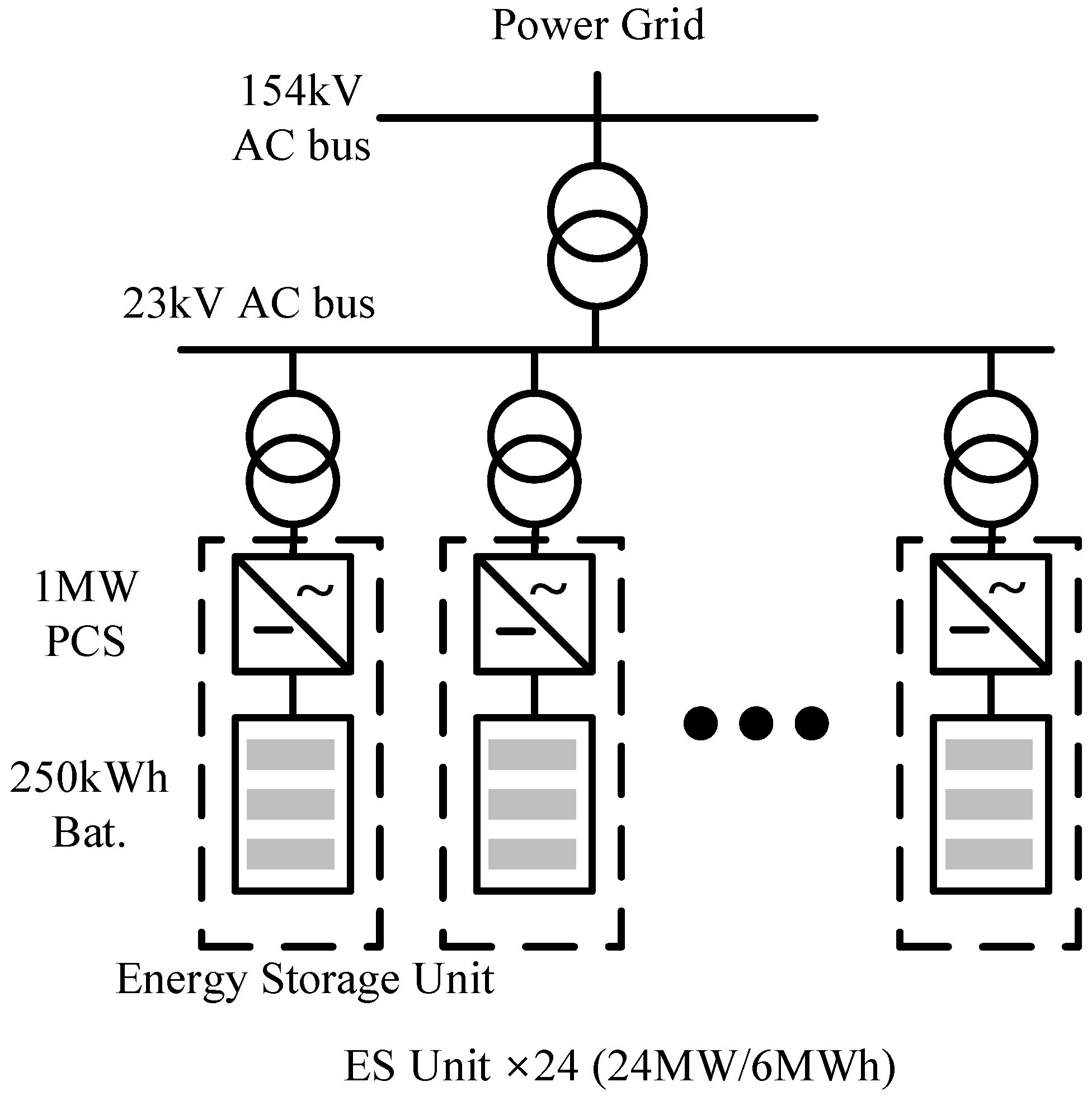
Figure 2.
Measured frequency data in Korea’s power system.

Figure 3.
ESS operation mode according to the frequency and state of charge (SOC).

Figure 4.
ESS power output according to the change in frequency.
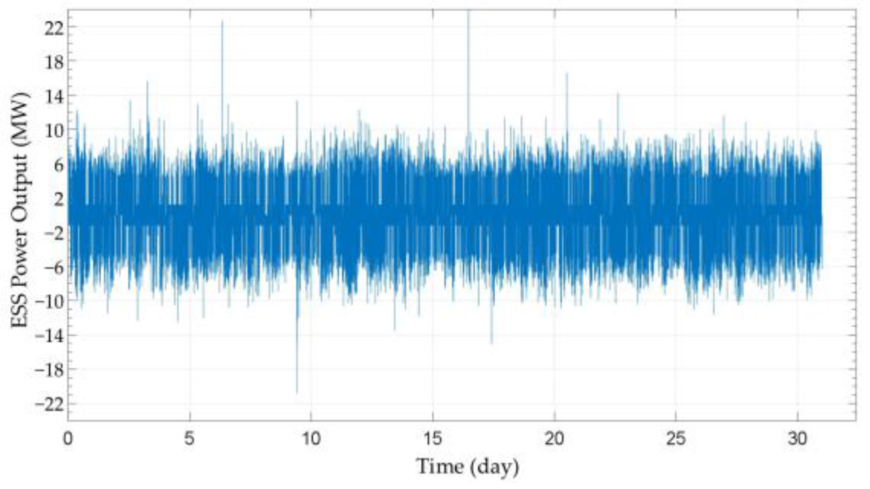
Figure 5.
Energy storage unit (ESU) operation efficiency and distribution according to the uniformly assigned power.
Figure 5.
Energy storage unit (ESU) operation efficiency and distribution according to the uniformly assigned power.
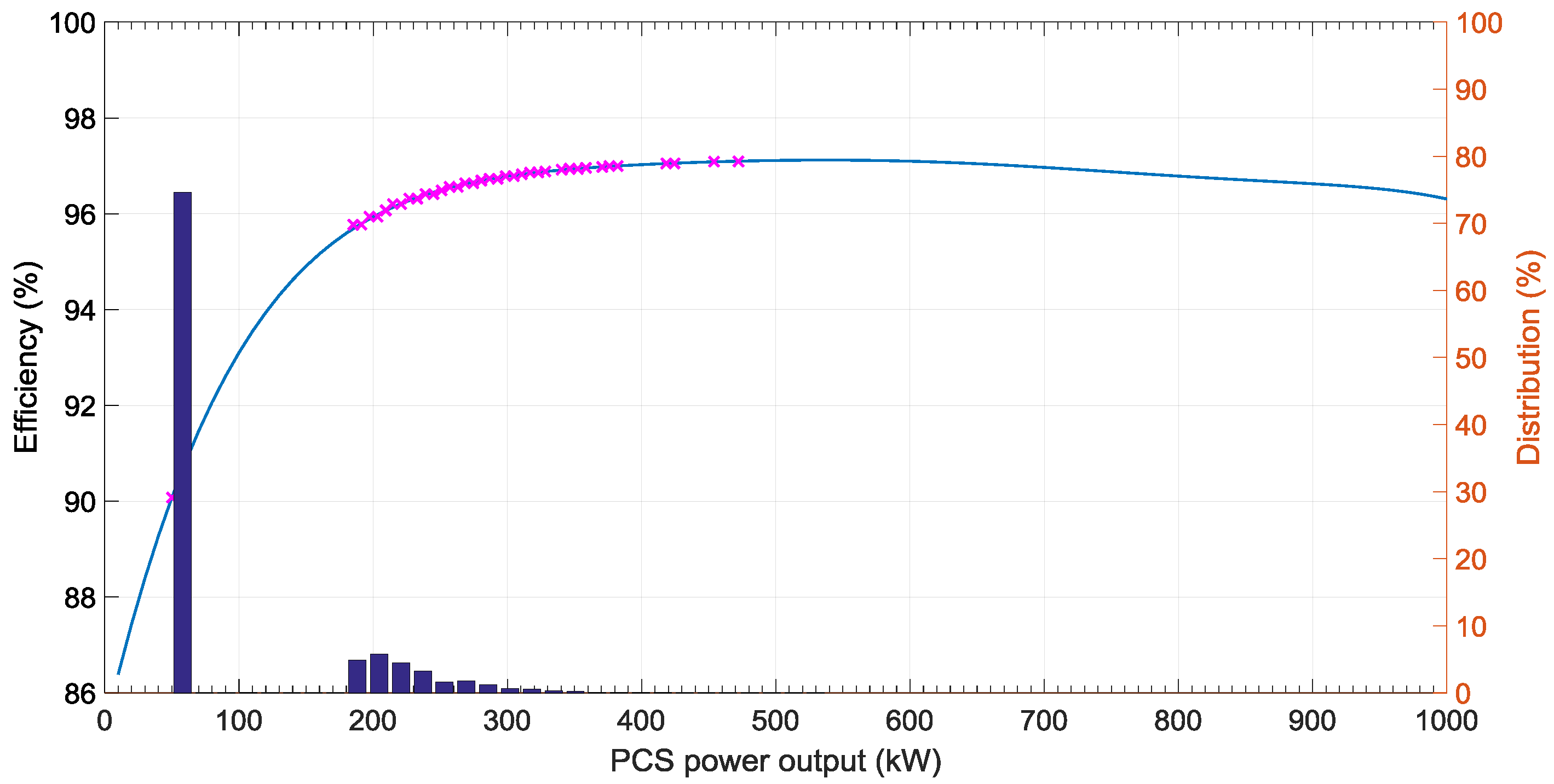
Figure 6.
Structure of string chromosome.

Figure 7.
Genetic algorithm flowchart for lookup table generation.
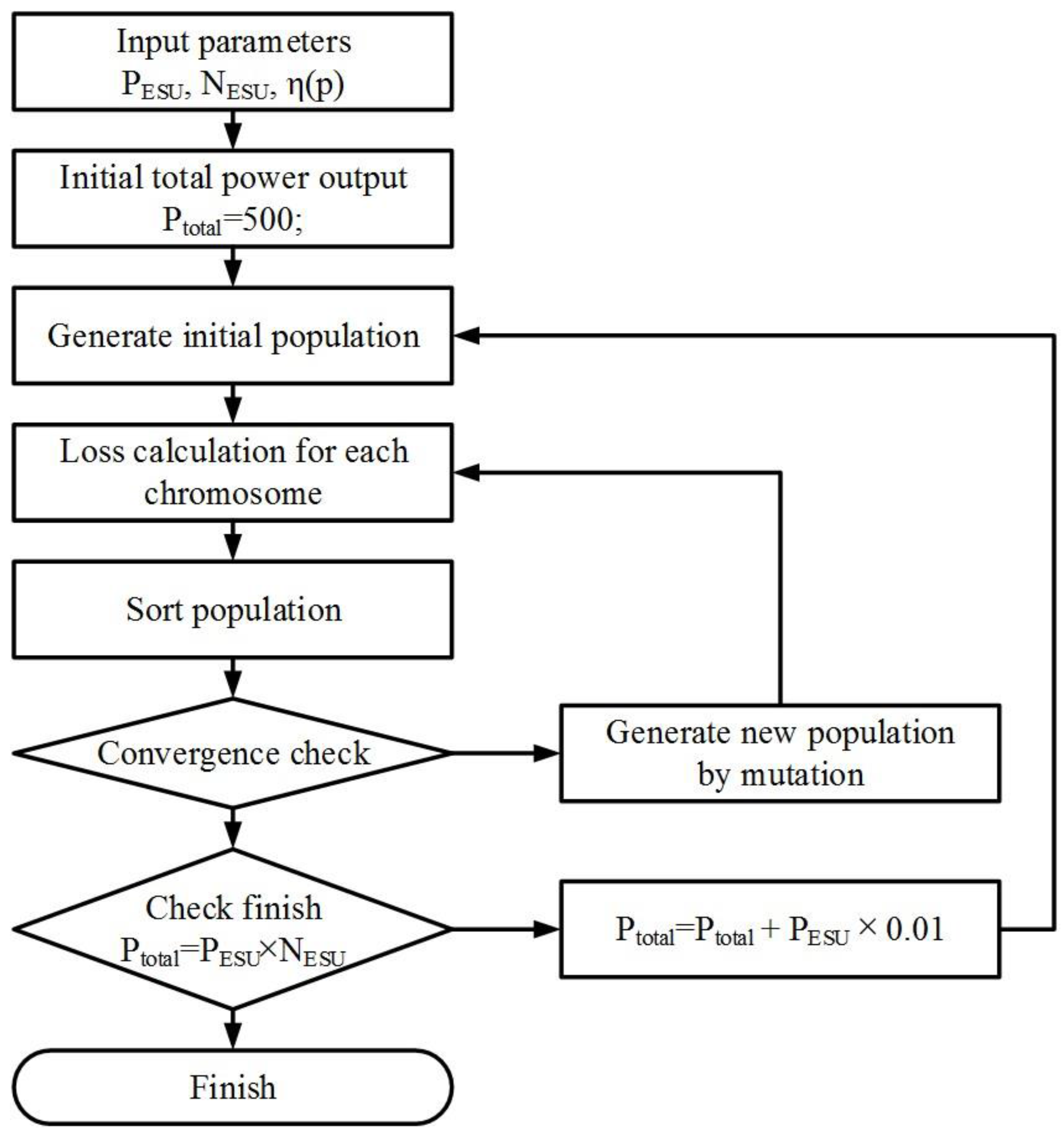
Figure 8.
Efficiency comparison between uniform and optimal assignment.

Figure 9.
ESU charge-discharge order by accumulative. Cumulatively charged energy (CCE); cumulatively discharged energy (CDE).
Figure 9.
ESU charge-discharge order by accumulative. Cumulatively charged energy (CCE); cumulatively discharged energy (CDE).

Figure 10.
Loss comparison between all-space search and genetic algorithm results: (a) ESU combinations, and; (b) loss by ESU combinations.
Figure 10.
Loss comparison between all-space search and genetic algorithm results: (a) ESU combinations, and; (b) loss by ESU combinations.

Figure 11.
Comparison of SOC change according to ESS operation model.
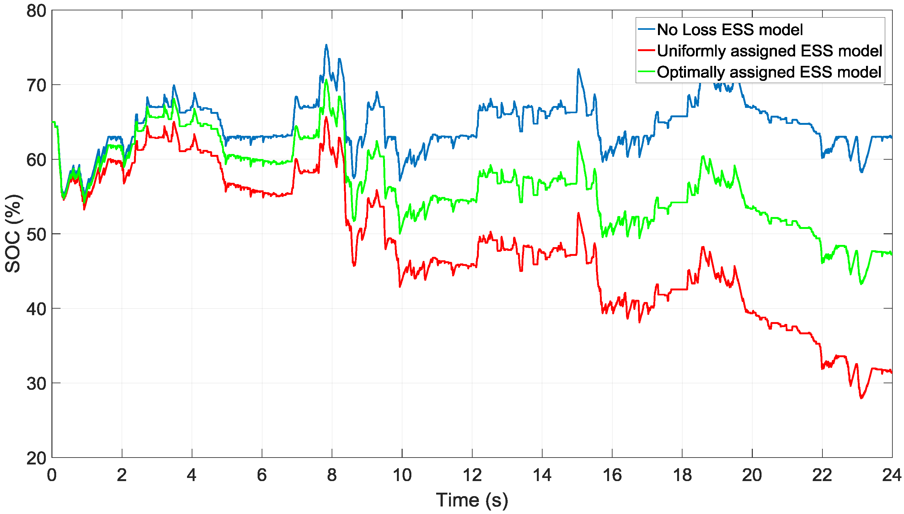
Figure 12.
ESU operation efficiency and distribution according to the optimally assigned power.
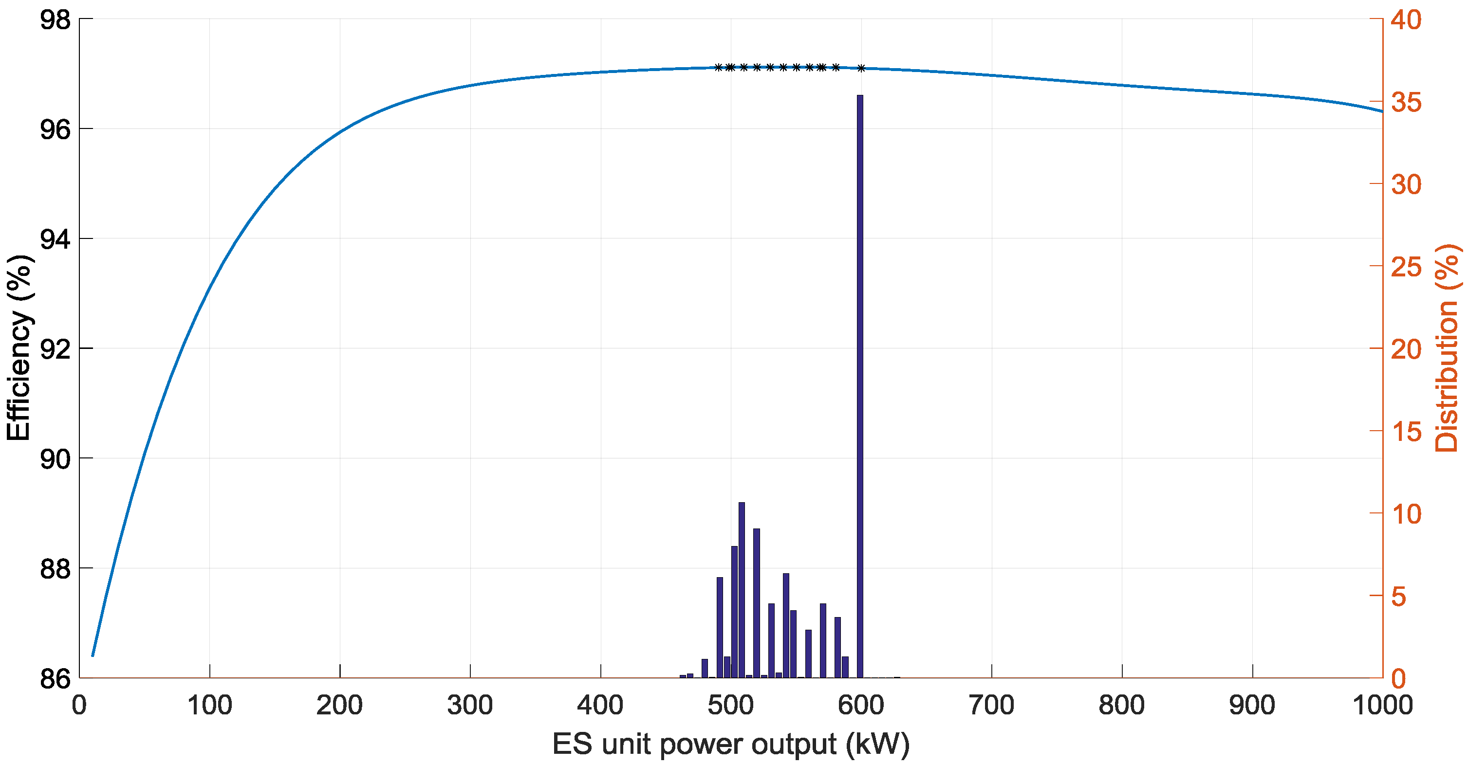
Figure 13.
Discharged energy distribution of ESUs according to operation time.

Figure 14.
Effect of loss on the frequency regulation operation: (a) Frequency; (b) ESS power output, and; (c) SOC.
Figure 14.
Effect of loss on the frequency regulation operation: (a) Frequency; (b) ESS power output, and; (c) SOC.

Table 1.
The structure of the lookup table for optimal power assignment.
| Total Power Output | Power Output ESU1 | Power Output ESU2 | Power Output ESU24 | Operation Unit | Efficiency |
|---|---|---|---|---|---|
| 500 kW | 500 kW | 0 | 0 | 1 | 97.112% |
| 510 kW | 510 kW | 0 | 0 | 1 | 97.116% |
| 23,980 kW | 1000 kW | 1000 kW | 980 kW | 24 | 96.314% |
| 23,990 kW | 1000 kW | 1000 kW | 990 kW | 24 | 96.311% |
Table 2.
Loss comparison between uniformly and optimally assigned power operations.
| Operation Strategy | Loss (kWh) | SOC at End Operation (%) |
|---|---|---|
| Optimal assignment | 2089.6 | 47.3 |
| Uniform assignment | 3743.2 | 31.5 |
Table 3.
FR operation comparison between the uniformly and optimally assigned power operations.
| Power Distribution Strategy | Charge (kWh) | Discharge (kWh) | Loss (kWh) | SOC at End Operation (%) |
|---|---|---|---|---|
| Optimally assigned | 373,764 | 352,371 | 21,002 | 66.44 |
| Uniformly assigned | 385,824 | 341,514 | 42,659 | 66.42 |
© 2017 by the authors. Licensee MDPI, Basel, Switzerland. This article is an open access article distributed under the terms and conditions of the Creative Commons Attribution (CC BY) license (http://creativecommons.org/licenses/by/4.0/).
Share and Cite
MDPI and ACS Style
Cho, S.-M.; Yun, S.-Y. Optimal Power Assignment of Energy Storage Systems to Improve the Energy Storage Efficiency for Frequency Regulation. Energies 2017, 10, 2092. https://doi.org/10.3390/en10122092
AMA Style
Cho S-M, Yun S-Y. Optimal Power Assignment of Energy Storage Systems to Improve the Energy Storage Efficiency for Frequency Regulation. Energies. 2017; 10(12):2092. https://doi.org/10.3390/en10122092
Chicago/Turabian StyleCho, Sung-Min, and Sang-Yun Yun. 2017. "Optimal Power Assignment of Energy Storage Systems to Improve the Energy Storage Efficiency for Frequency Regulation" Energies 10, no. 12: 2092. https://doi.org/10.3390/en10122092
Note that from the first issue of 2016, this journal uses article numbers instead of page numbers. See further details here.