A New Thin Seam Backfill Mining Technology and Its Application


1
College of Mining and Safety Engineering, Shandong University of Science and Technology, Qingdao 266590, China
2
State Key Laboratory of Mining Disaster Prevention and Control Co-founded by Shandong Province and the Ministry of Science and Technology, Shandong University of Science and Technology, Qingdao 266590, China
3
Graduate School of Engineering, Nagasaki University, Nagasaki 852-8521, Japan
4
China Coal Research Institute, Beijing 100013, China
*
Author to whom correspondence should be addressed.
Energies 2017, 10(12), 2023; https://doi.org/10.3390/en10122023
Submission received: 20 October 2017
/
Revised: 20 November 2017
/
Accepted: 27 November 2017
/
Published: 1 December 2017
Abstract
:Backfill mining is an effective way to control ground subsidence and govern gangue. To solve the problem of thin coal seam mining under villages, a new thin seam backfill mining technology was proposed. This paper investigated a reasonable proportion of filling materials by experiments, designed the filling system and introduced key technologies for thin seam working face filling. Finally, an industrial test of thin seam backfill mining technology was carried out in the C1661 working face, Beixu Coal Mine. The results show that the developed filling material meets both the pumping liquidity and strength requirements of the filling body during the early and late stages. The design and equipment selection of the paste filling system were reasonable. By using the key technologies for thin seam working face filling, the time needed for working face filling, the connection and disconnection of the filling pipeline and gob-side entry retaining were all greatly shortened. The labor intensity of the workers was reduced, and the mechanization level of the mine was improved. A fill mining length of 480 m was successfully completed. With effective roof subsidence control, the ground subsidence can be reduced, and good results can be achieved. This study can contribute to the development of backfill mining in thin coal seams.
1. Introduction
Coal is the most important energy resource in China and occupies an absolutely dominant position in China’s energy resources. The development and utilization of coal resources have greatly promoted the development of China [1,2]. However, at present, the coal resources under good mining conditions, such as in shallow buried and large thickness settings, in the eastern part of China have been gradually depleted [3]. To ensure the balance of the mine production capacity, extend the service life of the mine, and improve the recovery rate of resources, some mines must turn into coal resources with relatively difficult mining conditions, such as thin coal seams and coal seams under villages [4]. However, in thin coal seam mining, there are many rock tunnels, and a large amount of gangue is produced. The problems of gangue transportation and environmental pollution of gangue hills are very prominent [5]. With the exploitation of coal and gangue, the rock movement and surface subsidence will intensify [6]. In the process of mining under villages, the problems of subsidence area governance and the treatment of the relationship between the workers and peasants have caused certain economic pressure and unstable factors to the coal enterprises [7,8,9]. Filling mining technology can effectively control the overlying strata and surface subsidence, can protect the ground structures and ecological environment and is conducive to safe production [10,11,12]. This technology opens up a new technical method for coal mining under villages in China [13]. According to different production and geological conditions, various filling mining technologies have been studied, such as hydraulic backfill, high-water material filling, solid backfilling and paste backfill mining [4,14,15,16,17]. However, previous studies on backfill mining technology are mostly aimed at medium-thick coal seams [18,19], and most of the advanced filling and mining equipment are developed for thick coal seams only. Because of the limited activity and operating space, suitable filling and mining equipment for thin seams is limited, and most of the work can only be performed by workers. Hence, thin coal seam backfill mining faces many problems, such as slow filling speed, high labor intensity and low labor production efficiency, and the thin seam filling mining technology is inadequate at present. During the development process of backfill mining technology, improving efficiency and reducing the filling cost have long been key research highlights [1]. Hence, this paper aims to develop a filling mining technology of a high mechanization degree that is suitable for thin seam backfill mining and that can reduce labor intensity, improve work efficiency and increase economic benefits.
The geological and geotechnical overview is first introduced. This section is followed by the introduction of the new thin seam backfill mining technology, including the development of filling material, the design of a filling system and the key technologies for thin seam working face filling. Then, a field test was carried out on the proposed innovative thin seam backfill mining technology in an underground coal mine, and the test results are analyzed. Finally, we discuss the application of this new technology and present our conclusions. This technology can greatly contribute to the development of backfill mining in thin coal seams.
2. Geological and Geotechnical Overview
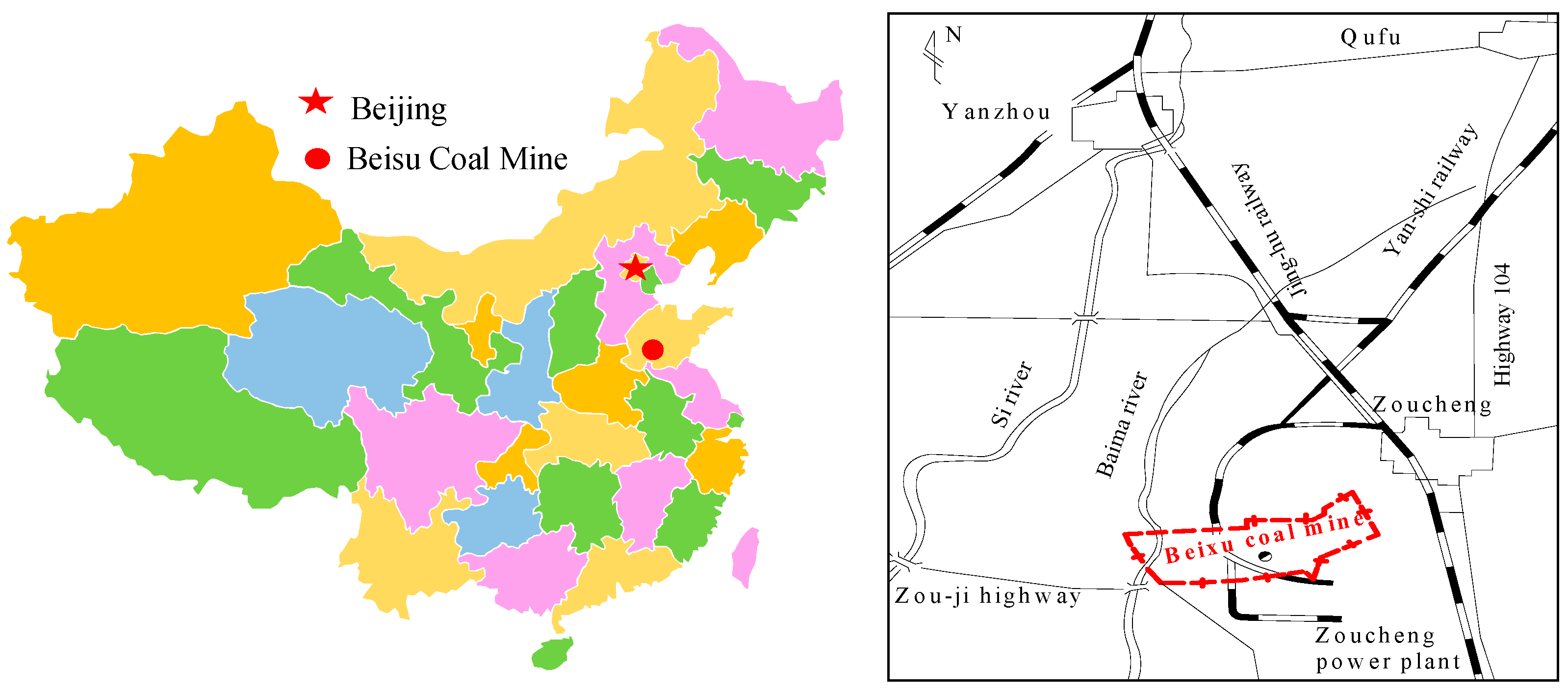
The Beixu coal mine is located in Zoucheng City, Shandong, China, as shown in Figure 1. This mine is a thin coal seam mine; the main recoverable coal seams are the 16U and 17 coal seams, and the thickness of the 16U coal seam ranges from 0.60 m to 1.42 m, with an average thickness of 0.94 m. The thickness of the 17 coal seam ranges from 0.57 m to 1.24 m, with an average thickness of 0.99 m. The recoverable reserves of the 16U coal and 17 coal seams under villages reach 22.682 million tons. This issue restricts the production of coal and affects the economic benefit and safety stability of the coal mine. Therefore, it is urgent to solve the problem of coal mining under the villages in the Beixu mine area. The Beixu Coal Mine is a thin seam mine, so there are many rock tunnels that produce a large quantity of gangue. The transportation of gangue and the environmental pollution of a gangue hill are also very prominent. Using goaf filling technology by pumping gangue slurry to carry out coal mining under the village can not only control the surface subsidence but it can also release the coal under the village. This will greatly ease the situation of coal production difficulties and extend the mining life of the Beixu Coal Mine.
2.1. Working Face Overview
The C1661 working face is located east of the Dong Ji Gou village and is the first mining face under the village of the sixteenth mining area. The surface projection location is located 700 m south of the mining area railway. The C1661 working face adopts an inclined longwall tilt mining layout, and the length of the working face is from 98 m to 123 m, with an average length of 116.1 m. The inclined length is from 475 m to 486 m, the average length is 480.5 m, and the average buried depth of the coal seam is 311.44 m.
2.2. Coal Seam and Strata
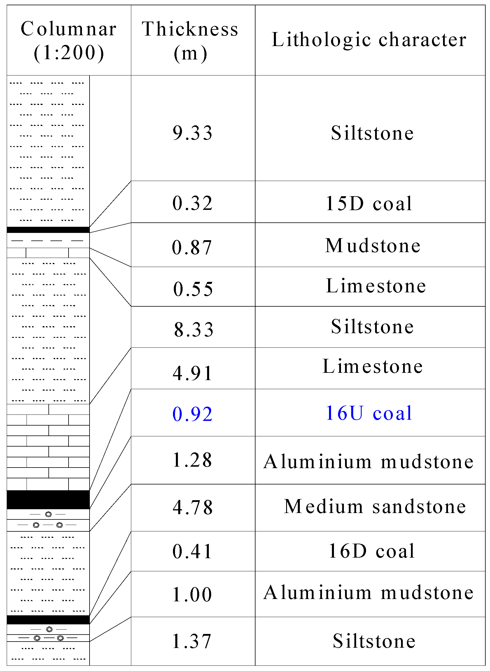
The C1661 working face mines 16U coal, and the thickness of the coal seam is from 0.80 m to 1.01 m, with an average thickness of 0.92 m. The Platts coefficient (f) of the coal seam is 1.25–2.5. The pyrite nodules are locally trapped and the horizon is unstable. The 16U coal is 26.24 m to 40.42 m away from the 15 coal seam, with an average of 33.52 m, and is 8.76 m to 13.37 m away from the 17 coal seam, with an average of 11.07 m. The direct roof of coal seam is limestone with an average thickness of 4.91 m; the coal seam floor is aluminum mudstone, which is easy to expand. Figure 2 shows the stratigraphic column with the lithologic characters of the C1661 working face.
2.3. The Mining Method
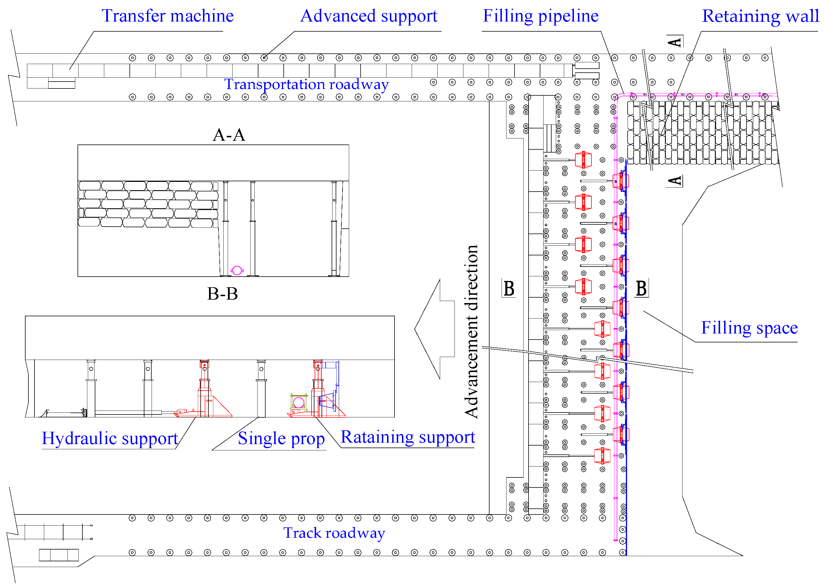
The inclined longwall blasting mining method is adopted in the C1661 working face, and the working face is supported by single props, namely, “π” type steel beams, retaining supports and small hydraulic supports. The filling method is adopted in the roof management of the gob. The mixed filling material is transported to the filling face by the filling pump through the pipeline. A schematic diagram of the mining method in the backfill mining working face is shown in Figure 3.
2.4. The Situation of the Ground Village
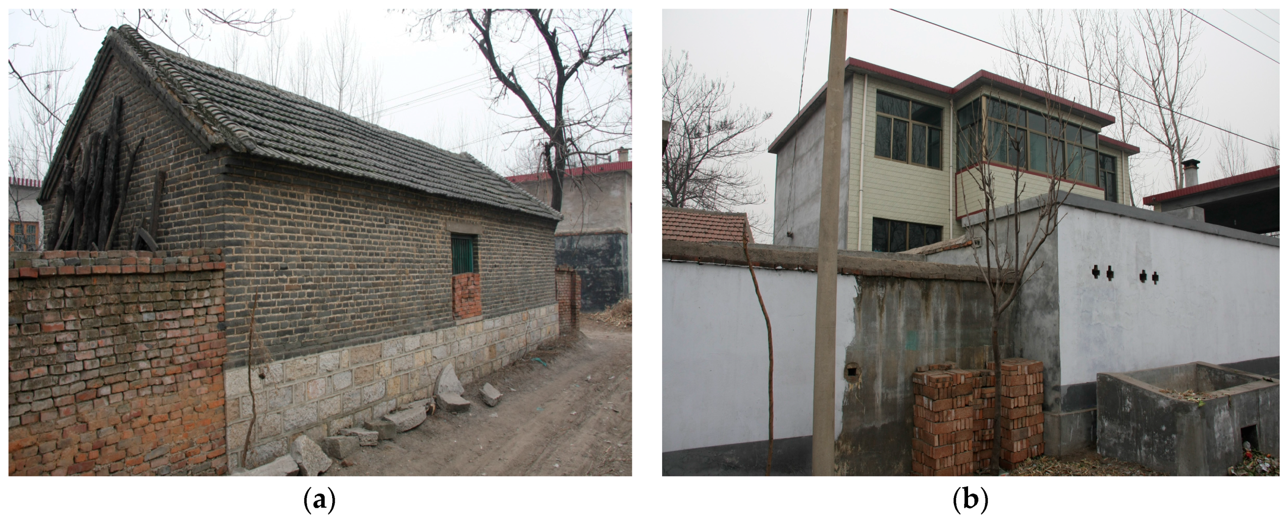
There are 640 households in the Dong Ji Gou Village; the construction area per household is 100 square m, and the total construction area is approximately 60,000 square m. The entire village consists of typical northern rural wooden structure houses, usually three or four together, and the length is generally not more than 20 m, as shown in Figure 4a. In recent years, the village built many brick-concrete structure houses, as shown in Figure 4b. Some houses with long service life and poor quality were demolished. At present, new planning is still ongoing. First-class rubble foundation brick houses account for approximately 70% of the total number of households and have better resistance to deformation. However, because the doors and windows contain flat bricks and reinforced bricks, they are more sensitive to surface deformation. Therefore, deformation or cracks easily occur in the windows and doors.
3. A New Thin Seam Backfill Mining Technology
3.1. The Development of the Filling Material
3.1.1. Raw Materials
(1) Coal Gangue
The roadway excavation in the Beixu coal mine discharged a large amount of coal gangue materials. There are some clay rocks and mudstone in the coal gangue, which disintegrates to a large extent under saturated water conditions, and the strength of the coal gangue will be reduced after disintegration. The clay component in coal gangue influences the activity of fly ash, which can affect the cementation quality of the paste. In addition, clay has a greater influence on the cement added to paste. Based on electron microscope analysis of the coal gangue composition, the mineral composition of the mudstone gangue of the Beixu coal mine was obtained, as shown in Table 1. The particle size distribution of coal gangue is an important parameter to determine the amount of fly ash and whether the gangue can be pumped [20]. According to the requirements of the pump, the gangue particle size must be less than 30 mm. There are some large particles in the gangue of Beixu coal mine. Therefore, the particles must be broken to achieve the coal gangue size requirements.
(2) Fly Ash
The role of fly ash in the gangue filling material is very important. The addition of fly ash in a slurry can cause the coal gangue of different particle size gradings to be slippery, facilitate easy flow and form gangue filling material suitable for pumping. At the same time, the addition of fly ash into the slurry makes the gangue filling cementation easier. The quality of fly ash from different power plants is also different. The gangue filling material made of fine granularity fly ash is easy to pump and has a high cementation strength. Sufficient fly ash can be provided by the Zouxian power plant surrounding the Beixu coal mine, and its technical indicators are shown in Table 2.
3.1.2. Experimental Study on the Performance of the Filling Material
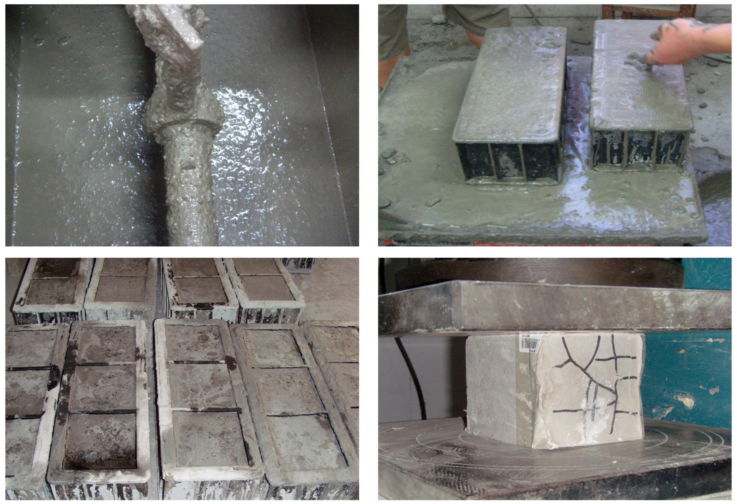
The gangue filling material suitable for pumping pipeline transportation in a coal mine should exhibit very good flow performance, smoothly flow through the pipeline [22] and meet the strength requirements of the gangue filling body in both the early and late stages [23]. To ensure the proper slump of filling material, the ratio of water to fly ash is 1:1, and the proper amount of gangue and cement is studied in the filling material performance experiment. According to the experimental results, the slumps of the filling material are 0 mm, 0 mm, 90 mm and 210 mm, when the ratios of water, fly ash and gangue are 1:1:10, 1:1:8, 1:1:6 and 1:1:4, respectively. Therefore, the final experimental ratio of water, fly ash and gangue is 1:1:4. To study the influence of cement on the strength of the gangue filling materials, cement is added on the basis of the benchmark ratio. The contents of the cement are 0%, 5%, 10% and 20% (the proportion of fly ash content). The experimental process is shown in Figure 5, which mainly includes material stirring, specimen pouring, specimen curing and uniaxial compression testing. The amount of materials and the test results are shown in Table 3.
The test results show that when the filling material does not include cement, the gangue filling material is formed after 24 h but is not completely condensed and is soft as time progresses. Additionally, the coal gangue filling material gradually hardens, but until the fifteenth day, is still not completely solidified and does not exhibit pressure test conditions, and its strength cannot be measured. Its 28-day compressive strength is only 0.35 MPa. It can be seen from the experiments that cement facilitates the increase in the strength of the filling material. When cement is added to the filler, the filling material has formed better after 24 h and completely condenses as time goes on; the strength of the filling material with cement increased faster than without cement and has pressure bearing capacity on the second day. The 28-day compressive strengths are 0.35 MPa, 1.45 MPa, 1.46 MPa and 1.48 MPa when the contents of the cement are 0%, 5%, 10% and 20%, respectively. As the cement increases, the strength of the filling material increases, as shown in Figure 6. However, when the cement content is more than 5%, the increase in the strength of the filling material is not obvious. Generally, when cement is added, the filling material can have a certain strength in the early stage, which is very favorable for supporting the roof of the gob as soon as possible; considering economic factors, the 5% content of the cement is more appropriate.
3.2. Design of the Filling System
3.2.1. Filling System
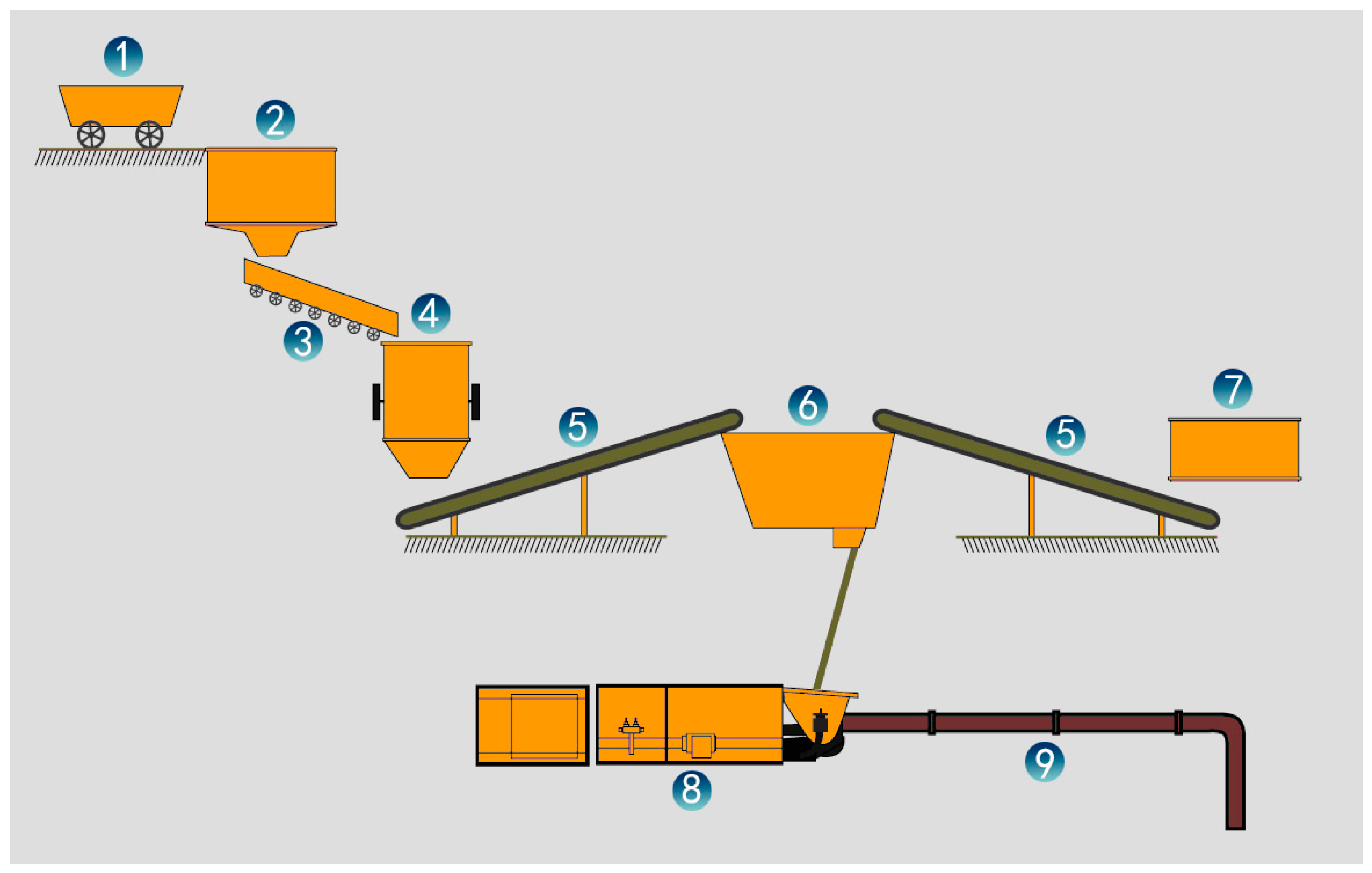
According to the characteristics of the large excavation quantity of rock roadway of the Beixu coal mine, the gangue transportation, storage and crushing system of the backfill mining technology were designed. The mixing of the gangue paste filling material and long-distance pipeline pumping system were developed, as shown in Figure 7. The gangue produced in the driving face is loaded into the tramcar and then transported to the dump chamber of the West Lane through the main roadway of district rise, district dip and district station. At the dump chamber, the gangue is turned into a small gangue bunker and then transported to the gangue crusher by a scraper conveyor. When filling the mined-out area, the broken gangue is transported to the mixer by belt conveyor, then, broken gangue, fly ash, cement and water are mixed together. Finally, the mixed filling material is transported to the filling face by the filling pump through the pipeline.
3.2.2. Parameters and Equipment Selection of the Filling System
The appropriate flow velocity of gangue filling material during pipeline transportation mainly depends on two aspects: one is the production capacity need, and the other is the pipeline wear speed. When the flow rate is small, it cannot meet the needs of the production capacity; when the flow rate is accelerated, the pipeline resistance that the gangue filling material needs to overcome will increase, and the pipeline wear speed will also accelerate. Therefore, the design flow velocity of the gangue filling material of the C1661 filling working face is 1–1.5 m/s. The actual maximum conveying distance from the filling pump to the filling working face is 1180 m. The theoretical conveying horizontal length of HBMD80F/16 filling pump (The Tyan Public Lok Machinery Manufacturing Co., Ltd, Taian, China) is 1300 m, and it meets the requirement. In addition, according to the filling amount of the working face, the calculation of the filling equipment selection is carried out. The model and parameters of the equipment are shown in Table 4.
3.3. Key Technologies for Thin Seam Working Face Filling
3.3.1. Retaining Support
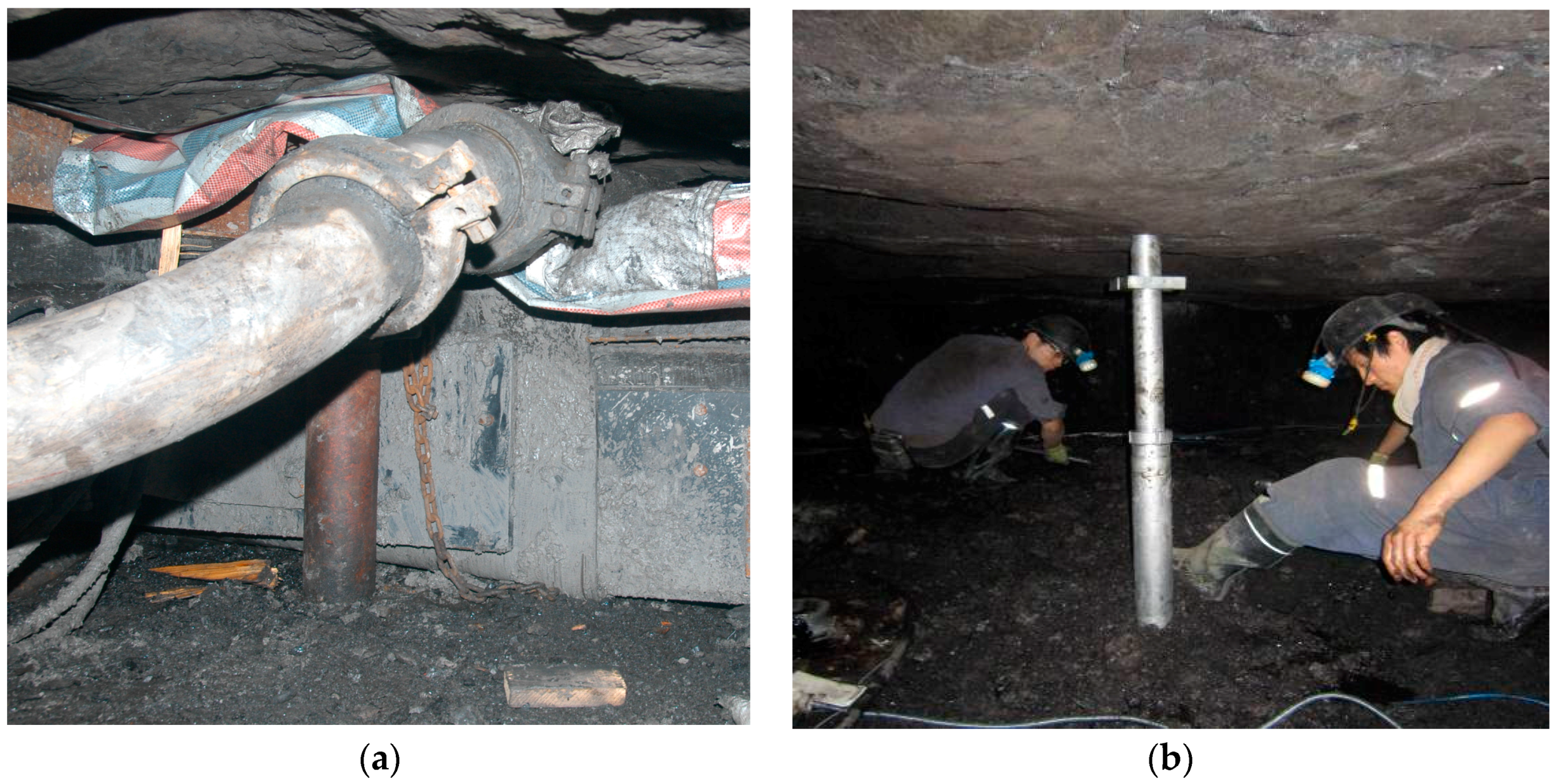
Preventing the overflow of filling material from the filling space is the key technology in filling mining. However, the original technology, which uses a single prop, bamboo sheathing and a waterproof plastic cloth to erect the retaining wall to prevent the overflow of the filling material, as shown in Figure 8a, has many restrictions regarding filling efficiency during thin seam mining. These restrictions are because of the limited activity and operating space of the workers, as shown in Figure 8b. Moreover, the labor intensity of workers is high, and the speed of erecting and removing the retaining wall is slow. In addition, the effect of preventing the overflow of filling material is poor. There is still no better solution to the problem. Hence, the filling material retaining support for thin seam mining has been developed in this paper.
The retaining support is a kind of two pillar support that mainly consists of metal structural parts, hydraulic components and a filling material retaining wall, as shown in Figure 9. The support can adapt to the coal seam thickness of 750–1100 mm, effectively support the roof and retain the filling material. The support has a long cycle life. The gangue retaining wall has the advantages of strong deformation resistance, light weight and good durability. The support is a high reliability retaining support that meets the needs of thin coal seam filling mining technology.
3.3.2. “Y” Type Two-Way Selection Cut-off Gate
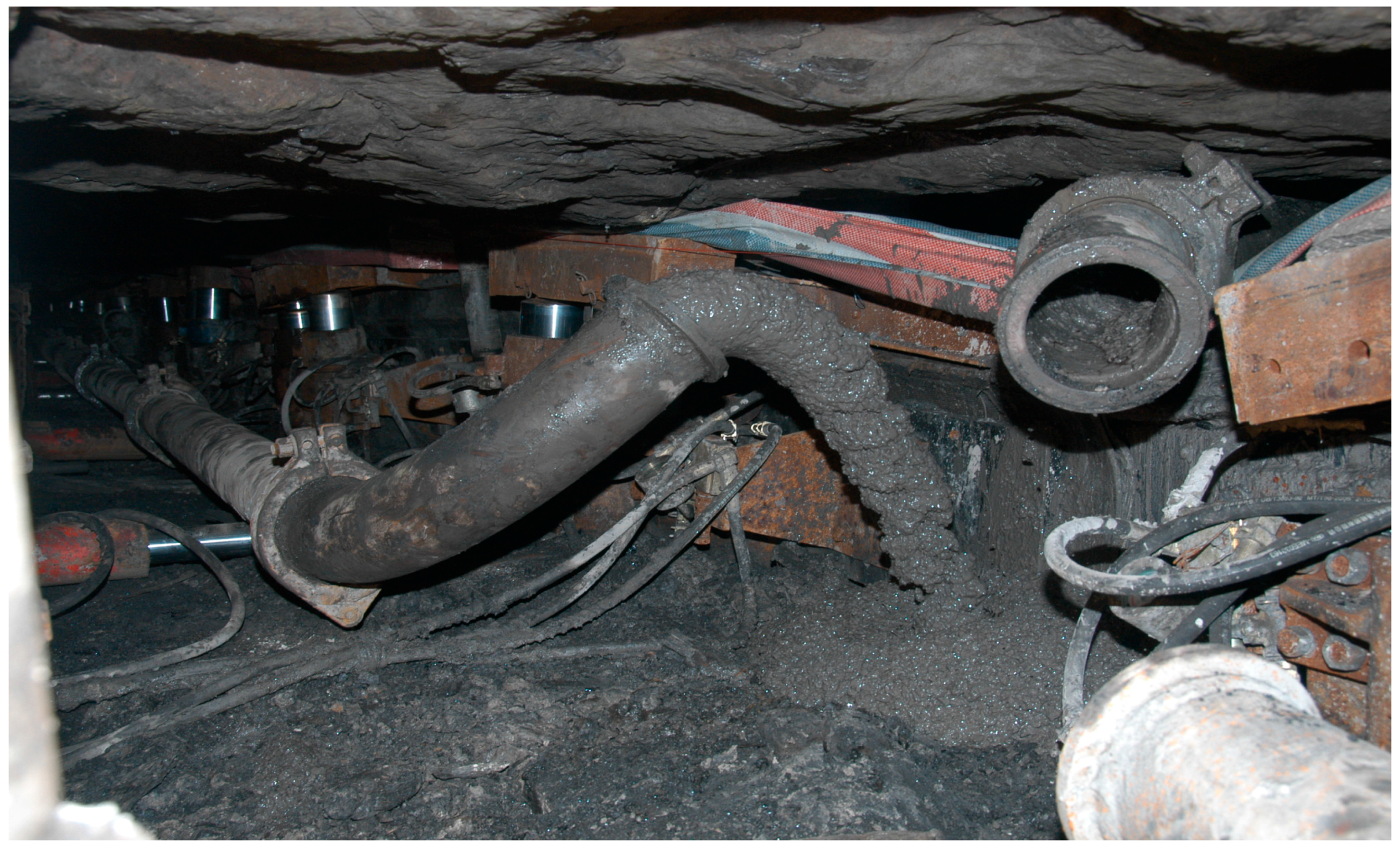
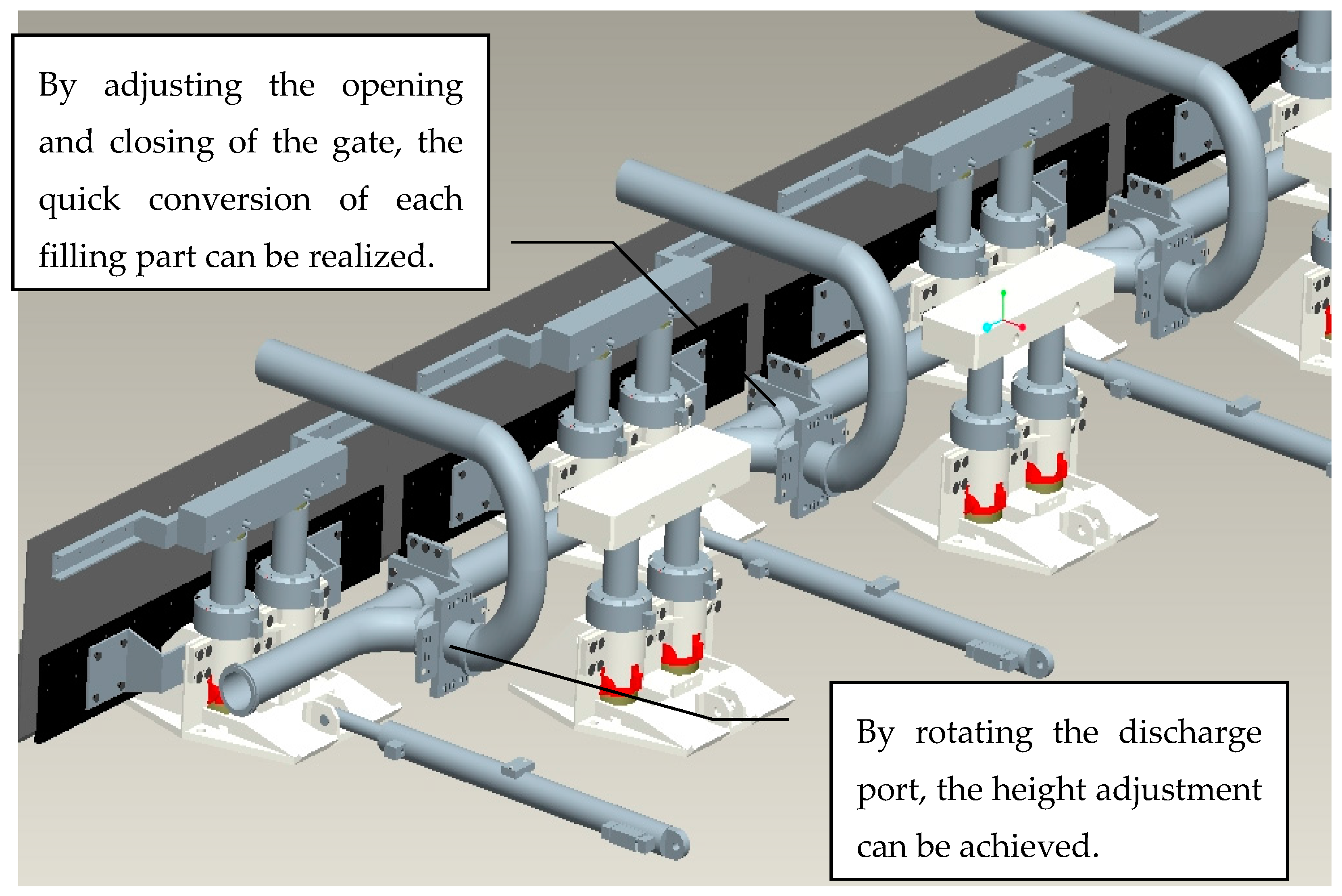
The length of longwall mining face is usually more than 100 m, and the flow range of the filling slurry is limited. Filling from only one site cannot fill the gob, so it needs to be divided into many parts, and the length of each part is approximately 10 m. When a part is completed, the next part will carry out the connection and disconnection of the filling pipeline, as this necessary auxiliary procedure greatly influences the filling efficiency. Especially in thin seam filling mining, this procedure is extremely difficult because the operation space is narrow and because the conveying pipeline is heavy, as shown in Figure 10. Therefore, this procedure will become key to the efficiency of thin seam filling mining. To solve this problem, a “Y” type two-way selection cut-off gate was developed in this paper.
The cut-off gate is mainly composed of a standard flange, steel pipe and flashboard. The gate is connected to the feeding inlet of the main road, discharge outlet of the main road and branch pipe outlet, as shown in Figure 11. The gate valve has a compact structure with a length of 500 mm and a height of 360 mm. By adjusting the opening and closing of the gate, the quick conversion of each filling part can be realized effectively. By loosening the pipe and rotating the discharge port, the height adjustment can be achieved. The cut-off gate has good adaptability to the working face of thin coal seam below a 1.0 m.
3.3.3. Gob-Side Entry Retaining
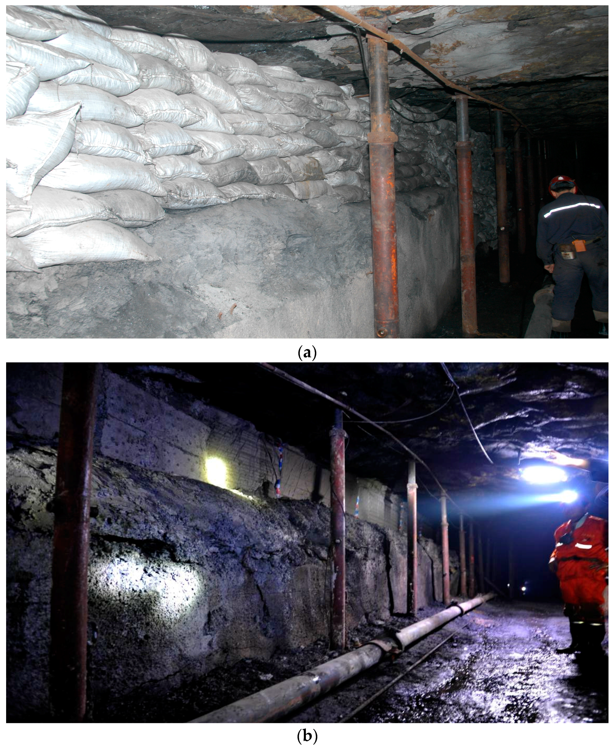
Gob-side entry retaining can enhance the coal recovery rate, reduce roadway drivage ratios and extend the service life of a mine. In general, an artificial wall is needed on the gob side of the entry so that the cross section of retained entry can still satisfy the service requirement after deformation [24]. During the early stage of C1661 mining, bagged gangue is used as the retaining wall along the side of a roadway, as shown in Figure 12. However, because the workers are required to move and pile up the gangue bags, this method has many disadvantages, such as a high labor intensity and the requirements of more manpower and a long period for completion. During the process of this practice, the entry retaining technology with filling material is gradually improved using a single prop, bamboo sheathing and a waterproof plastic cloth to erect the retaining wall. The strength of the filling body is improved by adding extra cement and fly ash into the filling gangue slurry. The velocity of gob-side entry retaining can be greatly improved by direct filling of paste material with the filling pump. In addition, this method has advantages of rapid molding, high strength and good sealing.
4. Roof Control Effect of Backfilling Mining
In the C1661 working face of the Beixu coal mine, the industrial testing of the thin seam backfill mining technology was carried out. The main purpose of filling mining is to avoid surface subsidence and the destruction of surface buildings by controlling the roof sink of the gob. However, because there are too many buildings on the ground, surface deformation observation is not convenient. Therefore, the roof subsidence and stress of the gob are observed to check the filling effect.
4.1. Installation of the Observation Instrument
The gob cannot be entered for observation after filling, so the observation instrument adopts special sensors that can automatically monitor and transmit signals through the line. The stress monitoring instrument is a GYW25 digital stress sensor (Uroica Precision Information Engineering Co., Ltd, Taian, China), and the roof subsidence monitoring instrument is a KBU101-200 displacement sensor (Uroica Precision Information Engineering Co., Ltd, Taian, China). The flow of the filling during the filling process can cause the observation instrument to lose its stability and affect normal monitoring of the data, so the instrument is fixed by an anchor bolt during the installation process, as shown in Figure 13. To avoid the crushing of the sensor communication cable, the cable is set into a one-inch steel pipe and connected to the main station of the C1661 track roadway. The stations are arranged in the gob. Each station has three sets of measuring points located at the top, middle and lower parts of the working face, as shown in Figure 14.
4.2. Result Analysis
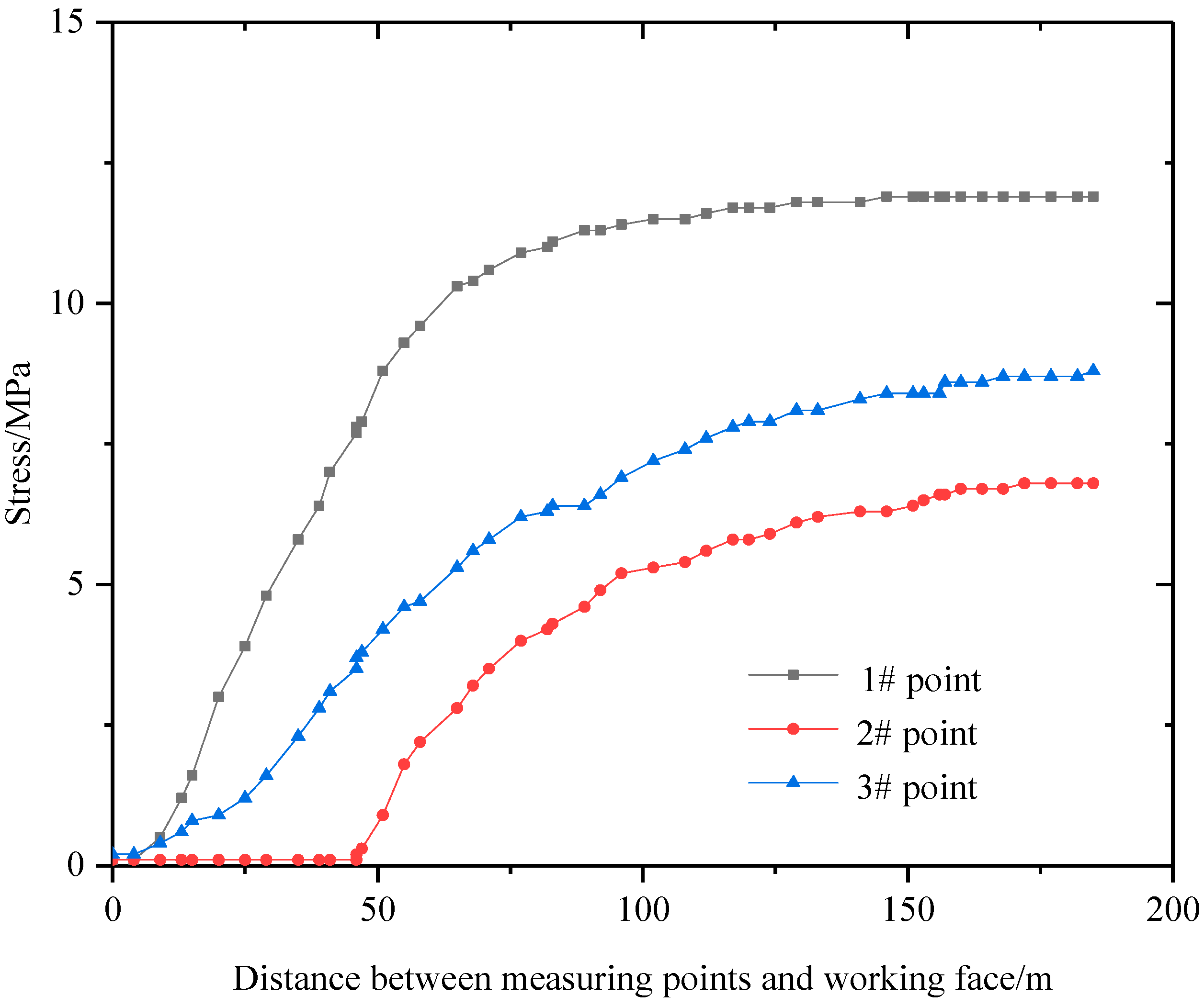
The values of stress acting on the filling body measured by the stress sensors are shown in Figure 15. The results show that the roof subsidence curve of the three measuring points basically exhibited the same change trend. First, with the advancement of the working face, the stress rapidly increased; next, when the distance between measuring points and working face was approximately 100 m, the stresses at the 1#, 2# and 3# points were 11.5 MPa, 5.6 MPa and 7.6 MPa, respectively. Then, the rate of the stress increase became slower. Finally, when the distance between measuring points and working face was more than 150 m, the stress tended to be stable; the final stresses at the 1#, 2# and 3# points were 11.9 MPa, 6.8 MPa and 8.8 MPa, respectively. The monitoring data at the 2# point remained unchanged during the early stage. The reason was that the filling body failed to touch the roof, and the stress sensor did not bear the pressure from the roof. When the distance between measuring points and working face was 46 m, the filling body touched the roof, and the stress sensor began to bear the pressure from the roof. Then, the 2# point began to enter a normal working state, which correctly reflects the roof movement law.
The values of roof subsidence measured by the displacement sensors are shown in Figure 16. It can be seen that the roof subsidence curve of the three measuring points exhibits the same change trend. First, with the advancement of the working face, the roof subsidence rapidly increased. Next, when the distance between measuring points and working face was 50 m, the roof subsidence rates at the 1#, 2# and 3# points were 185.3 mm, 191.1 mm and 242.3 mm, respectively; then, the roof subsidence rate became slow. When the distance between measuring points and working face was more than 100 m, roof subsidence tended to be stable; the final roof subsidence rates at the 1#, 2# and 3# points were 194.9 mm, 213.7 mm and 255.9 mm, respectively.
5. Discussion
To develop a filling mining technology of high mechanization degree which is suitable for thin seam backfill mining and can reduce labor intensity, improve work efficiency and increase economic benefits, the filling material, filling system and key technologies were studied. The application effect of filling technology is as follows: (1) The slump of filling material is 220 mm. The filling material was formed in one day and solidified in seven days, and the 28-day strength of filling material reached 1.45 MPa. Hence, the developed cemented gangue filling material can meet both the pumping liquidity and the strength requirements of the filling body during early and late stages; (2) The long distance (1180 m) pumping of the filling material was realized, and a filling mining length of 480 m was successfully completed in the working face. During this process, the operation of the filling system was coordinated to meet the requirements of long-term continuous operation of the filling project. This finding proves that the design and equipment selection of paste filling system were reasonable; (3) By using a retaining support, the time of working face filling was reduced from 10 h to 8 h, which avoided the replacement of 30 heavy pier columns per month, and the number of single prop replacements was reduced by 1/3. The labor intensity of the workers was reduced, and the number of workers needed decreased by three. The mechanization level of the mine was improved; the rental cost of 80 pier columns and 300 single props per year was reduced by 77.015 million yuan, which greatly reduced the cost of production; (4) Through the use of a “Y” type two-way selection cut-off gate, the time for the connection and disconnection of the filling pipeline was reduced from 30 m to 5 m, and rapid filling was realized. The labor intensity of the workers was greatly reduced, and the number of workers needed decreased by four; (5) By using the technology of entry retaining with filling material, the time needed for each gob-side entry retaining was shortened from 4 h to 1 h, and the number of workers needed decreased from ten to four. The labor efficiency was greatly improved, and the workload was small. The support strength of filling body is high, which can effectively protect the gob-side entry; (6) Taken together, with the advancement of the working face, the stresses acting on the filling body and the roof subsidence of the filling area were first increased rapidly, and then, the increase rate decreased gradually when the distance of the working face advancement was greater than approximately 80 m. When the working face was advanced by approximately 120 m, the filling body gradually reached its ultimate strength and became stable, and as a result, the stress and roof subsidence were no longer changing. These results show that if the roof subsidence is effectively controlled, then the ground subsidence can be reduced, and good results can be achieved.
6. Conclusions
In this paper, a new thin seam backfill mining technology was proposed as a solution for mining thin coal seams under villages in the Beixu coal mine. In the C1661 working face, an industrial test of thin seam backfill mining technology was carried out, and a filling mining length of 480 m was successfully completed. The following major conclusions were drawn:
- (1)
- When the ratio of water to fly ash to gangue is appropriate and proper cement is added, the developed cemented gangue filling material can meet both the pumping liquidity and the strength requirements of the filling body during the early and late stages.
- (2)
- The operation of the filling system was coordinated to meet the requirements of long-term continuous operation of the filling project. The design and equipment selection of the paste filling system were reasonable.
- (3)
- By using the key technologies for thin seam working face filling, the time needed for working the face filling, the connection and disconnection of the filling pipeline and gob-side entry retaining were all greatly shortened. The labor intensity of the workers was reduced, and the mechanization level of the mine was improved.
- (4)
- With the advancement of the working face, the stresses acting on the filling body and the roof subsidence of the filling area were first increased rapidly. When the distance of the working face advancement was more than approximately 80 m, the increase rate gradually decreased, and when the working face was advanced by approximately 120 m, the filling body gradually reached its ultimate strength and became stable. As a result, the stress and roof subsidence were no longer changing. These results show that if the roof subsidence is effectively controlled, then the ground subsidence can be reduced, and good results can be achieved.
The new technology developed filling material, designed the filling system and studied the key technologies for thin seam working face filling such as the retaining support, “Y” type two-way selection cut-off gate and gob-side entry retaining. Through this new technology, the problems of low efficiency and high cost in thin coal seam backfill mining were solved, which can greatly contribute to the development of backfill mining in thin coal seams.
Acknowledgments
This work is supported by the National Natural Science Foundation of China (No. 51379117 and No. 51479108), Scientific Research Foundation of Shandong University of Science and Technology for Recruited Talents (2015RCJJ048) and Provincial Natural Science Foundation of Shandong Province, China (ZR2017PEE018).
Author Contributions
All the authors contributed to publishing this paper. Yujing Jiang and Hengjie Luan contributed to the formulation of the overarching research goals and aims; Hengjie Luan and Huili Lin contributed to the filling material experiments, filling system design and industrial testing; and Yahua Wang contributed to the application effect analysis.
Conflicts of Interest
The authors declare no conflict of interest.
References
- Zhu, W.; Xu, J.; Xu, J.; Chen, D.; Shi, J. Pier-column backfill mining technology for controlling surface subsidence. Int. J. Rock Mech. Min. 2017, 96, 58–65. [Google Scholar] [CrossRef]
- Chen, S.; Yin, D.; Cao, F.; Liu, Y.; Ren, K. An overview of integrated surface subsidence-reducing technology in mining areas of China. Nat. Hazards 2016, 81, 1129–1145. [Google Scholar] [CrossRef]
- Yin, W.; Chen, Z.; Quan, K.; Mei, X. Strata behavior at fully-mechanized coal mining and solid backfilling face. SpringerPlus 2016, 5. [Google Scholar] [CrossRef] [PubMed]
- Li, H.; Guo, G.; Zhai, S. Mining scheme design for super-high water backfill strip mining under buildings: A Chinese case study. Environ. Earth Sci. 2016, 75. [Google Scholar] [CrossRef]
- Chang, Q.; Chen, J.; Zhou, H.; Bai, J. Implementation of Paste Backfill Mining Technology in Chinese Coal Mines. Sci. World J. 2014, 2014, 1–8. [Google Scholar] [CrossRef] [PubMed]
- Farhad Howladar, M.; Mostafijul Karim, M. The selection of backfill materials for Barapukuria underground coal mine, Dinajpur, Bangladesh: Insight from the assessments of engineering properties of some selective materials. Environ. Earth Sci. 2015, 73, 6153–6165. [Google Scholar] [CrossRef]
- Wu, D.; Yang, B.; Liu, Y. Transportability and pressure drop of fresh cemented coal gangue-fly ash backfill (CGFB) slurry in pipe loop. Powder Technol. 2015, 284, 218–224. [Google Scholar] [CrossRef]
- Liu, J.; Sui, W.; Zhao, Q. Environmentally sustainable mining: A case study of intermittent cut-and-fill mining under sand aquifers. Environ. Earth Sci. 2017, 76. [Google Scholar] [CrossRef]
- Zhang, Q.; Zhang, J.; Kang, T.; Sun, Q.; Li, W. Mining pressure monitoring and analysis in fully mechanized backfilling coal mining face—A case study in Zhai Zhen Coal Mine. J. Cent. South Univ. 2015, 22, 1965–1972. [Google Scholar] [CrossRef]
- Wu, D.; Sun, G.; Liu, Y. Modeling the thermo-hydro-chemical behavior of cemented coal gangue-fly ash backfill. Constr. Build. Mater. 2016, 111, 522–528. [Google Scholar] [CrossRef]
- Ma, F.; Zhao, H.; Yuan, R.; Guo, J. Ground movement resulting from underground backfill mining in a nickel mine (Gansu Province, China). Nat. Hazards 2015, 77, 1475–1490. [Google Scholar] [CrossRef]
- Sivakugan, N.; Rankine, R.M.; Rankine, K.J.; Rankine, K.S. Geotechnical considerations in mine backfilling in Australia. J. Clean. Prod. 2006, 14, 1168–1175. [Google Scholar] [CrossRef]
- Zhou, N.; Zhang, J.; Yan, H.; Li, M. Deformation Behavior of Hard Roofs in Solid Backfill Coal Mining Using Physical Models. Energies 2017, 10, 557. [Google Scholar] [CrossRef]
- Zhang, J.; Gao, R.; Li, M.; Cao, S.; Liu, S. Basic Characteristics and Effective Control of Gangue Piles in Mining Areas: A Case Study. J. Residuals Sci. Technol. 2015, 12, S145–S154. [Google Scholar] [CrossRef]
- Huang, Y.; Zhang, J.; Yin, W.; Sun, Q. Analysis of Overlying Strata Movement and Behaviors in Caving and Solid Backfilling Mixed Coal Mining. Energies 2017, 10, 1057. [Google Scholar] [CrossRef]
- Zhang, J.; Zhang, Q.; Spearing, A.J.S.S.; Miao, X.; Guo, S.; Sun, Q. Green coal mining technique integrating mining-dressing-gas draining-backfilling-mining. Int. J. Min. Sci. Technol. 2017, 27, 17–27. [Google Scholar] [CrossRef]
- Huang, Y.; Li, J.; Song, T.; Kong, G.; Li, M. Analysis on Filling Ratio and Shield Supporting Pressure for Overburden Movement Control in Coal Mining with Compacted Backfilling. Energies 2017, 10, 31. [Google Scholar] [CrossRef]
- Li, M.; Zhang, J.; Huang, Y.; Zhou, N. Effects of particle size of crushed gangue backfill materials on surface subsidence and its application under buildings. Environ. Earth Sci. 2017, 76. [Google Scholar] [CrossRef]
- Zhang, J.; Zhang, Q.; Sun, Q.; Gao, R.; Germain, D.; Abro, S. Surface subsidence control theory and application to backfill coal mining technology. Environ. Earth Sci. 2015, 74, 1439–1448. [Google Scholar] [CrossRef]
- Zhang, X.; Lin, J.; Liu, J.; Li, F.; Pang, Z. Investigation of Hydraulic-Mechanical Properties of Paste Backfill Containing Coal Gangue-Fly Ash and Its Application in an Underground Coal Mine. Energies 2017, 10, 1309. [Google Scholar] [CrossRef]
- China State Adminstration of Quality Supervision. Spection and Quarantine; GB/T1596–2005 Flyash used for cement and concrete [S]; Standards Press of China: Beijing, China, 2005.
- Witteman, M.L.; Simms, P.H. Unsaturated flow in hydrating porous media with application to cemented mine backfill. Can. Geotech. J. 2017, 54, 835–845. [Google Scholar] [CrossRef]
- Qi, T.; Feng, G. Resistivity and AE Response Characteristics in the Failure Process of CGB under Uniaxial Loading. Adv. Mater. Sci. Eng. 2017, 2017, 1–11. [Google Scholar] [CrossRef]
- Gong, P.; Ma, Z.; Zhang, R.R.; Ni, X.; Liu, F.; Huang, Z. Surrounding Rock Deformation Mechanism and Control Technology for Gob-Side Entry Retaining with Fully Mechanized Gangue Backfilling Mining: A Case Study. Shock Vib. 2017, 2017, 6085941. [Google Scholar] [CrossRef]
Figure 1.
Position of the Beixu Coal Mine.

Figure 2.
The stratigraphic column with the lithologic characters.

Figure 3.
Schematic diagram of the mining method in the backfill mining working face.

Figure 4.
Buildings in the villages: (a) Northern rural wooden structure houses; (b) Brick-concrete structure building.
Figure 4.
Buildings in the villages: (a) Northern rural wooden structure houses; (b) Brick-concrete structure building.

Figure 5.
Photos of the experimental process.

Figure 6.
Influence of cement content on the strength of the filling material.
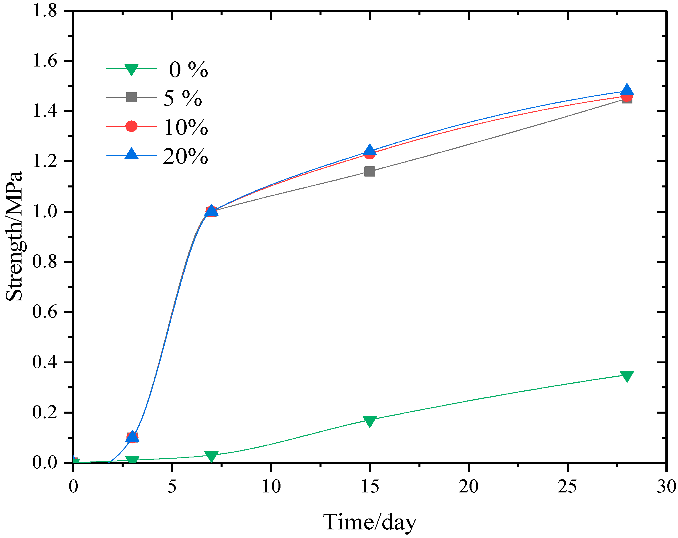
Figure 7.
Sketch map of the space layout of the filling system. 1: Gangue tramcar; 2: Gangue bunker; 3: Scraper conveyor; 4: Gangue crusher; 5: Conveyer belt; 6: Filling material mixer; 7: Fly ash storage bin; 8: Filling pump; and 9: Filling pipeline.
Figure 7.
Sketch map of the space layout of the filling system. 1: Gangue tramcar; 2: Gangue bunker; 3: Scraper conveyor; 4: Gangue crusher; 5: Conveyer belt; 6: Filling material mixer; 7: Fly ash storage bin; 8: Filling pump; and 9: Filling pipeline.

Figure 8.
The original filling technology: (a) Preventing the overflow of the filling material (b) The limited activity and operating space.
Figure 8.
The original filling technology: (a) Preventing the overflow of the filling material (b) The limited activity and operating space.

Figure 9.
Retaining support: (a) Schematic diagram; (b) Pictures.
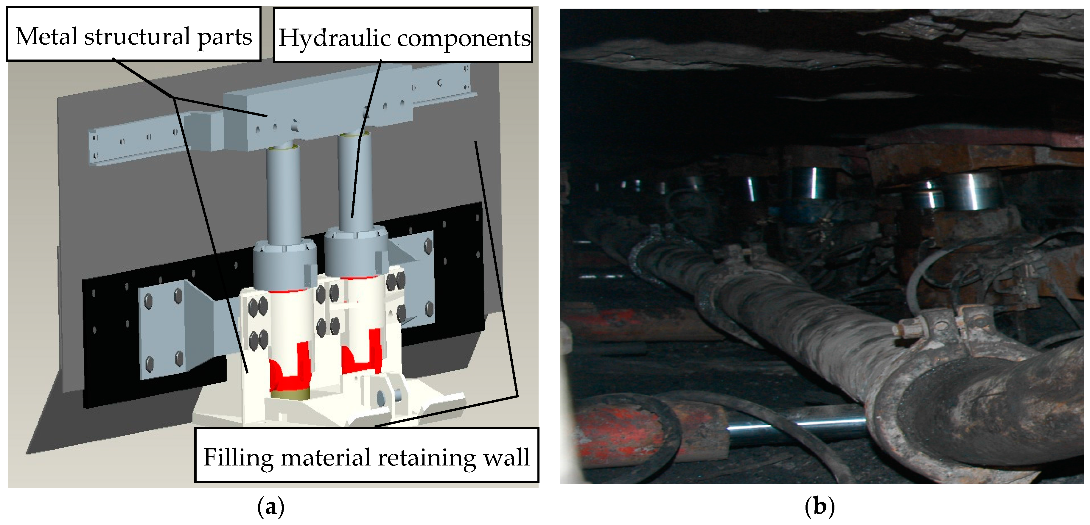
Figure 10.
The connection and disconnection of the heavy filling pipeline.

Figure 11.
Sketch map of the “Y” type two-way selection cut-off gate.

Figure 12.
Photos of gob-side entry retaining: (a) Gob-side entry retaining with a bagged gangue wall; (b) Gob-side entry retaining with filling material.
Figure 12.
Photos of gob-side entry retaining: (a) Gob-side entry retaining with a bagged gangue wall; (b) Gob-side entry retaining with filling material.

Figure 13.
Pictures of the site equipment installation: (a) a stress sensor and (b) a displacement sensor.
Figure 13.
Pictures of the site equipment installation: (a) a stress sensor and (b) a displacement sensor.
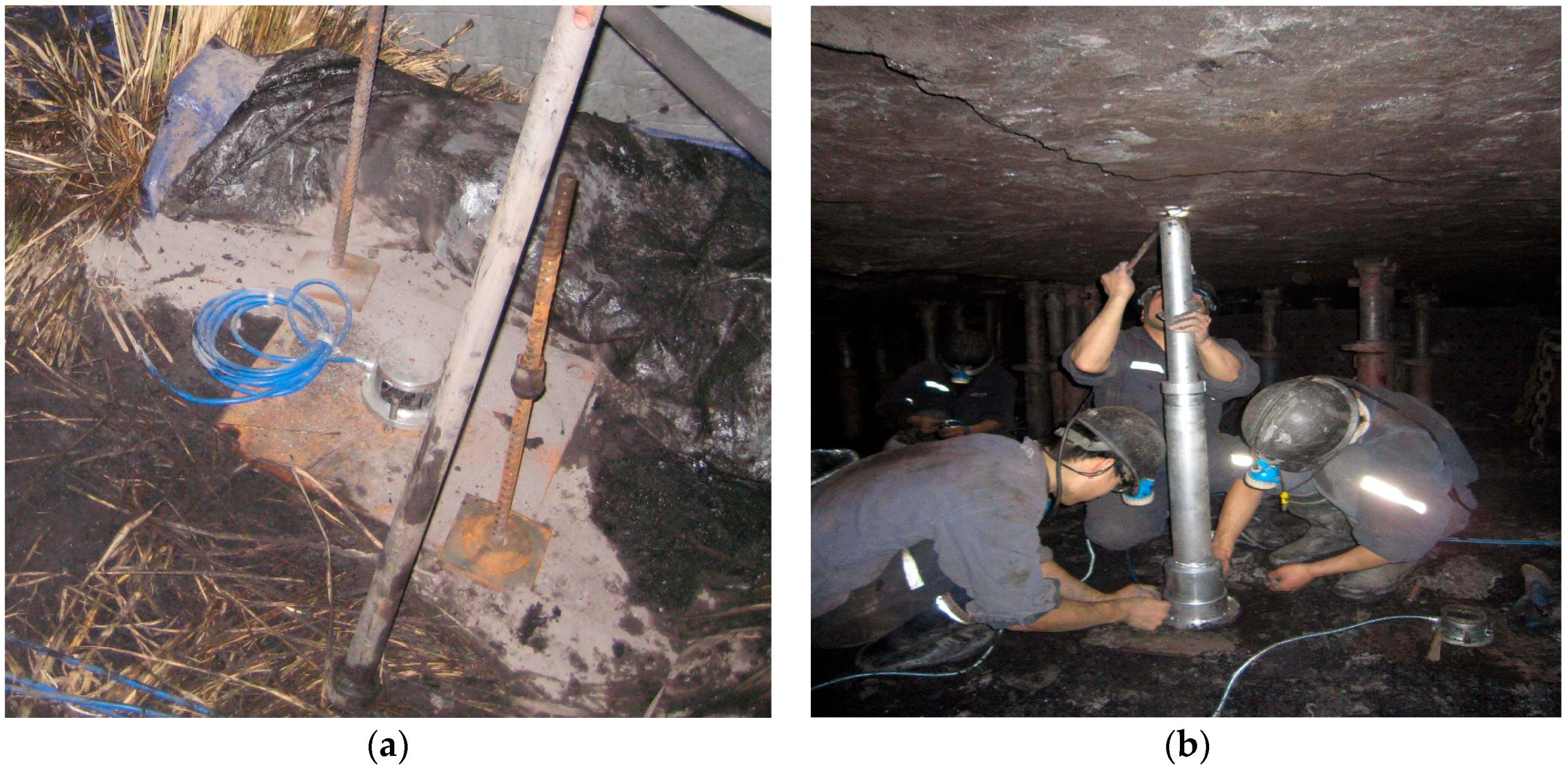
Figure 14.
Sketch map of the observation equipment layout.
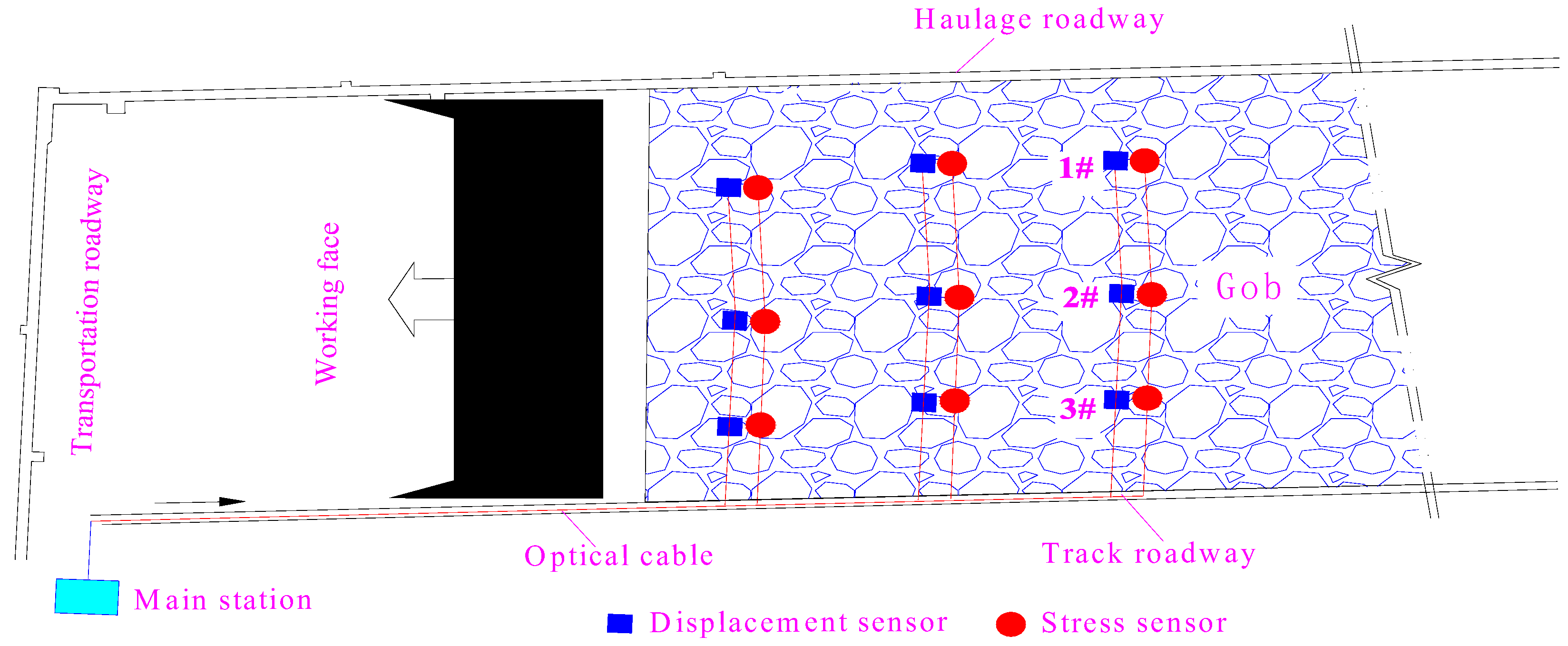
Figure 15.
Filling body stress of the gob.

Figure 16.
Roof subsidence of the gob.


Table 1.
The mineral composition of gangue (%).
| Montmorillonite | Kaolinite | Sericite | Jarosite | Carbonaceous Shale |
|---|---|---|---|---|
| 31.5 | 11.1 | 4.6 | 13.5 | 32.4 |
Table 2.
The technology indicators of fly ash in the Zouxian power plant.
| Test Item | Index Value [21] | Measured Value |
|---|---|---|
| Ignition Loss (%) | <5 | 0.95 |
| Moisture Content (%) | <1 | 0.65 |
| Sulphur Trioxide (%) | <3 | 0.81 |
| Water Demand Ratio (%) | <95 | 86 |
| Surface Area (cm2/g) | ≥6000 | 6700 |
Table 3.
Material contents and test results.
| Material (g) | Slump (mm) | Compressive Strength (MPa) | |||||||
|---|---|---|---|---|---|---|---|---|---|
| Water | Fly Ash | Gangue | Cement | 1 d | 3 d | 7 d | 15 d | 28 d | |
| 400 | 400 | 1600 | 0 | 210 | 0.0 | 0.0 | 0.0 | 0.0 | 0.35 |
| 400 | 400 | 1600 | 20 | 220 | 0.0 | 0.1 | 1 | 1.16 | 1.45 |
| 400 | 400 | 1600 | 40 | 230 | 0.0 | 0.1 | 1 | 1.23 | 1.46 |
| 400 | 400 | 1600 | 80 | 245 | 0.0 | 0.1 | 1 | 1.24 | 1.48 |
Table 4.
Filling equipment list.
| Equipment Name | Model | Motor Power (kW) | Rated Voltage (V) | Operational Capability |
|---|---|---|---|---|
| Crusher | PCS1000F | 110 | 660 | 80–90 t/h |
| Scraper Conveyor | SGW-40T | 40 | 660 | 200 t/h |
| Conveyer Belt | SDJ-800/75 | 75 | 660 | 300 t/h |
| Filling Pump | HBMD80F/16 | 110 | 660 | 80/40 m3/h |
| Mixer | JDY700L | 18.5 | 660 | 60 m3/h |
| Fly Ash Conveyor | QLS200 | 7.5 | 660 | 48 t/h |
© 2017 by the authors. Licensee MDPI, Basel, Switzerland. This article is an open access article distributed under the terms and conditions of the Creative Commons Attribution (CC BY) license (http://creativecommons.org/licenses/by/4.0/).
Share and Cite
MDPI and ACS Style
Luan, H.; Jiang, Y.; Lin, H.; Wang, Y. A New Thin Seam Backfill Mining Technology and Its Application. Energies 2017, 10, 2023. https://doi.org/10.3390/en10122023
AMA Style
Luan H, Jiang Y, Lin H, Wang Y. A New Thin Seam Backfill Mining Technology and Its Application. Energies. 2017; 10(12):2023. https://doi.org/10.3390/en10122023
Chicago/Turabian StyleLuan, Hengjie, Yujing Jiang, Huili Lin, and Yahua Wang. 2017. "A New Thin Seam Backfill Mining Technology and Its Application" Energies 10, no. 12: 2023. https://doi.org/10.3390/en10122023
Note that from the first issue of 2016, this journal uses article numbers instead of page numbers. See further details here.